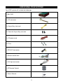
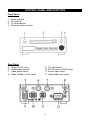
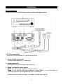
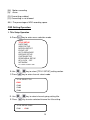
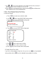
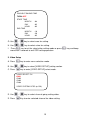
1
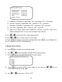
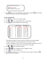
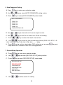
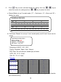
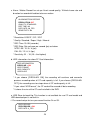
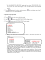
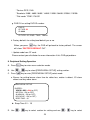
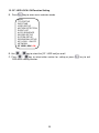
Mini Stand-Alone 1 Ch / 2 ~ 4 Ch
Sequence View & Record Mobile DVR
User Manual (104CF-A)
Please read this user manual completely before operating this DVR system and
keep it in a safe place for future reference.
TABLE OF CONTENTS
Table of Contents ………………………………………………………………………
1
Introduction ……………………………………………………………………………..
2
Important Safety Information …………………………………………………………
2
Unpacking Your System ………………………………………………………………
3
Control Panel and Function ……………………………………………….………….
5
Installation ………………………………………………………………………………
7
Before Operation ………………………………………………………………………
9
Operation ………………………………………………………………………………. 10
OSD (On Screen Display) Menu Setting Operation Process ………………….. 10
Key and function for operation ………………………………………….………… 10
OSD Setting Operation ……………………………………………………………. 13
Title Setup Operation …..………………………….……………………………. 13
Date / Time & Daylight Saving Time Setting ………...………………………… 14
Video Setup …………………………………………….….………….…………. 15
Motion Detect Setting …..…………………….……………...…….….…………. 16
Event List Selection ……………………………………………………………… 17
Auto Sequence Setting …………………………………………………………. 18
Record Setup Operation …………………………….…………………………… 18
System Setup Operation ……………………………...…………………………. 21
Peripheral Setting Operation ……….…………………..……………….………. 23
Key Lock Function Setting Operation …...…………….……………….………. 24
Network Setting Operation ………………...…………………………….………. 24
CF/HDD Lock: ON Function Setting ……...…………………………….………. 25
Play Back Record Data ……..……………………………………………….……….. 26
PTZ Camera Setting and Control ………………………………………….………… 27
PC Player Software Operation ……………………………………………………….. 29
1
INTRODUCTION
Thank you for purchasing our unique DVR system. To ensure that you optimize the full
capabilities of this product, please read this user’s manual before proceeding. Be sure
to keep this manual for future reference in case any problems or questions should
arise. We hope you enjoy your new DVR system.
IMPORTANT SAFETY INFORMATION
When using your DVR equipment, basic safety precautions should always be followed
to reduce the risk of fire, electric shock and personal injury. Please read the followings
before using your equipment:
1. Read and follow all instructions carefully.
2. Follow all warnings and instructions on the product.
3. Unplug the product from the power outlet before cleaning. Do not use liquid
cleaners or aerosol cleaners. Use a damp cloth for cleaning.
4. Do not use this product near water.
5. Do not place this product on an unstable cart, stand or table.
6. Do not allow anything to rest on the power cords. Do not place this product in a
location where the cords can be stepped on or where someone can trip over
them.
7. Do not use this product near an area where there is a potential of gas leaks or
near any explosive fumes.
8. Do not place this product near or over a radiator or any other heat source.
9. Use ONLY the power cord supplied with the system.
10. Do not overload the wall outlet or power cord where the power cord is
installed. This can result in fire or electric shock.
11. This equipment is to be opened by ONLY a qualified serviceperson. There are
no user serviceable parts inside. Opening this equipment may expose you to
dangerous voltage and other risks. Incorrect re-assembly of this equipment may
result in electric shock.
12. Avoid spilling liquid on this equipment and do not insert any objects through the
ventilation slots.
2
UNPACKING YOUR SYSTEM
Your DVR system will include the followings:
1 x Mini DVR
1 x DC connector
1 x Key on/Key start cord
2 x Cover for Key on/Key start wire
1 x DC power cord
2 x Fuse
1 x RCA A/V connector
1 x Sensor control wire
1 x A/V Input connector
1 x IR Remote Control
1 x User’s Manual
3
Optional Accessories
CF Card
Car rear view camera
Car rear view camera
CCD color dome camera
Shatter proof CCD color dome camera
Motion detector (Sensor)
Alarm
4
CONTROL PANEL AND FUNCTION
Front Panel
1.
2.
3.
4.
Power indicator
CF card slot
CF card indicator
IR remote control receiver
Rear Panel
5.
6.
7.
8.
Power On/Off switch
Audio output terminal
Video output socket
Mode 1/Mode 2 select switch
9. DC input socket
10. RS-232 signal to DVR socket
11. Sensor input socket
12. Video/Audio input socket
5
IR Remote Control
1.
Power On/Off button
2.
Menu button
3.
Record button
4.
PTZ button
5.
Up key (Camera 1)
6.
Down key (Camera 3)
7.
Left key (Camera 2)
8.
Right key (Camera 4)
9.
Select button
10.
Play button
11.
Fast forward button
12.
Fast back button
13.
Pause button
14.
Audio 1 button
15.
Audio 2 button
16.
Audio Mute button
17.
Zoom in button
18.
Zoom out button
19.
PTZ auto button
20.
6
~
Number keys
Installation
DVR Installation
Please refer to the installation process as the following drawing:
1. CF Card installation
Insert the CF card into the CF card slot of the DVR.
2. Audio output connection
Connect audio output to TV audio input.
3. Video connection
Connect the monitor to Video output terminal.
4. Mode 1 or Mode 2 select switch
Mode 1: 2~4 channels sequencing view & record.
Mode 2: One channel real time recording. Under Mode 2, it can also work on
switching record in case the detecting wire is connected.
Switch the select switch to mode 1 or mode 2 to meet your request.
7
5. System Camera installation
Connect one end of camera cable to Camera and the other end to Video Input
terminal at the back of DVR. Please number the camera by yourself for convenient
operation.
6. Detecting wire (Sensor control) connection
If you select Mode 2, you can also connect the detecting wire for switching record.
Connect the detecting wire to this socket. Please refer to the following drawing as
for the connecting.
6-1) It’s no need to connect detecting wire to 1 because it has been used for CH1
already.
6-2) When connect detecting wire to 2 or 3, the DVR will switch to CH2 or CH3 for
recording as soon as motion is detected.
6-3) When connect detecting wire to 4, it will record 4 channels in sequence as
panic function.
7. Power connection
a. Plug the power cord to Battery (e.g. car battery).
b. Plug the wire for Key [On] and key [Start] wire connection
Connect the key on connecting wire (yellow) to car key “ON” position.
Connect the key start wire (white) to car key “Start” position.
The built-in power supply with delay circuit board designed for DVR to delay
switch-on time for 10 seconds. With the delay, it can avoid DVR working on
unstable voltage.
Switch on/off voltage: 10.5 ~10.8V
Delay switch-on time while starting the car: 10 seconds
Note: The DVR switch-off delay function can work normally only when key on/key
start wire is correctly connecting.
8. Turn on and use the DVR system
Switch the power switch to “ON”. The DVR is ready to be used.
9. RS-232 signal connection (optional)
This socket can connect auto dialer box, tracking box or LAN box for future
requirement.
8
BEFORE OPERATION
(1) The system will auto detecting the hardware and enter Recording mode while
hardware is in normal condition.
(2) The system will show [UNKNOW HDD] then enter [Format Menu] within 3 seconds
when first time start the system or CF card is changed. Please select [FORMAT
HDD YES] to format CF card. The system will auto enter record mode after format
CF card. (Or, enter the Main menu “record setup” and select HDD information to
format the CF card.)
(3) If the system not setting time yet, will auto enter to time setting screen, please press
[MENU](ESC) key to exit after setting time.
(4) If [NO HD] signal show on screen, please turn off the power then check CF card is
exist or not. If yes, please turn the power on again.
(5) If screen show [NO VIDEO], please check video input connector whether is
connecting with camera correctly.
(6) Suggest turn on camera power before turn the system power on.
9
OPERATION
The system is preset [KEY LOCK] mode [OFF], when the system setting [KEY LOCK]
mode [ON], the screen will show below message:
PASSWORD:
****
Please key in the security code by remote control number keys to enter the OSD
manual for setting.
OSD (On Screen Display) Menu Setting Operation Process
1. Press [
] to enter menu selection mode.
2. Press up [
3. Press
] key or down [
] key to select the item for setting.
key to enter sub menu to select item for setting.
4. Press Left [
] key or Right [
] key to select the value for your setting.
5. Press
key to exist for other setting or Press
seconds to exit OSD menu setting function
key and keep more than 2
Key and Function for Operation
1、 MENU operation key
Key
MENU
(Up Key)
Remarks
Operation
Enter OSD menu
Go Up
10
1. Press
key to enter OSD
menu.
2. Press direction key to select.
3. Press
key to enter sub menu.
4. Press
setting.
to exit while end of
(Down Key)
Go Down
(Left Key)
Go Left
(Right Key)
Go Right
(Enter Key)
ENTER next page
2、 Play operation key
Key
Operation
PLAY
PLAY
FF
FAST FORWARD
FB
FAST BACK
P/S
PAUSE / STOP
Remarks
3、 REC operation key
Key
REC
Operation
Remarks
RECORD
4、 PTZ control key operation
Key
Operation
PTZ
PTZ
IN
ZOOM IN
OUT
ZOOM OUT
Remarks
1. Press
key to enter the
function.
2. Press function key to operate.
3. Press direction to select the area.
Go Up
Go Down
Go Left
Go Right
5、Display operation key
Key
AUTO
Operation
Remarks
Auto sequence view
11
The DVR system is preset to work in Mode 2. If you want to change it to Mode 1, please
switch the select switch to Mode 1. (The select switch is at the back of DVR.)
When the DVR system is power ON and on record mode,
1. Press FF key two times, FB key two times and
(Select) key two times. Then,
the following screen will be showed. If there are 2 channels or 1 channel selected,
then the other cameras setting under MENU will not function.
SELECT CHANNEL MODE
SELECT CHANNEL MODE: 1CH
SELECT PLAYBACK MODE: 1CH
2. Use
3. Press
/
key to select 4CH/2CH/1CH for setting.
key to exit.
a. Select Channel Mode: 4CH/2CH/1CH for select
b. Select Playback Mode: 4CH/1CH for select
Screen Instruction:
PANIC
LOSS1234
ACH1 CH01
[REC] 4CH [C][R] 99% 2006/01/01 18:08:08
[PANIC]: Press panic button and recording the event
[LOSS1234]: Camera loss will be found on the 1234.
[ACH1]: Audio in channel 1
[ACH2]: Audio in channel 2
[REC]: Recording
[LIV]: View mode (Without recording)
[BOT]: The DVR system is booting.
[PB]: Playback mode
4CH: 4 channels mode
[C]: Continuous recording
12
[M]: Motion recording
[A]: Alarm
[R]: Overwriting enabled.
[O]: Overwriting is not allowed.
99%: The percentage of HDD recording space.
OSD Setting Operation
1. Title Setup Operation
A. Press
key to enter menu selection mode.
MAIN
TITLE SETUP
DATE/TIME
VIDEO SETUP
MOTION DETECT
EVENT LIST
AUTO SEQUENCE
RECORD SETUP
SYSTEM SETUP
PERIPHERAL SETUP
KEY LOCK:OFF
NETWORK
CF /HDD LOCK: ON
B. Use
/
key to select [TITLE SETUP] setting section.
key to enter channel select mode.
C. Press
TITLE SELECT CH
CH01
CH02
CH03
CH04
D. Use
/
E. Press
key to select channel going setting title.
Key to enter selected channel for title setting.
TITLE SETUP CH01
CH01 : CH01
13
F. Use
/
key to select alphabet (A~Z) or digital (0~9) for title, maximum 4
alphabet or digits can be setting for one channel title.
key to exit for select other channel or press
G. Press
than 2 seconds to exit OSD setting operation.
key and keep more
2. Date / Time & Daylight Saving Time Setting
A. Date/Time Setting
a. Press
key to enter menu selection mode.
b. Use
/
c. Press
key to select [DATE/TIME] setting section.
key to enter [DATE/TIME] setting mode.
DATE/TIME
SETUP DATE/TIME
DAYLIGHT SAVING TIME
d. Press
key to enter [DATE/TIME] setting mode.
SETUP DATE/TIME
YEAR
: 2006
MONTH : 01
DAY
: 01
HOUR
: 18
MIN
: 08
SEC
: 08
MODE: YY:MM:DD
e. Use
/
key to select area for setting.
f. Use
/
key to select value for setting.
g. Press
key to exit for select other setting mode
B. Daylight Saving Time setting
If you want setting daylight saving time, then you can use
saving section and use
key to go daylight
key to turn daylight saving mode on for setting.
14
DAYLIGHT SAVING TIME
TURN: OFF
START TIME
MONTH
DAY
HOUR
END TIME
MONTH
DAY
HOUR
: 04
: 02
: 02
: 10
: 29
: 02
G. Use
/
key to select area for setting.
H. Use
/
key to select value for setting.
I.
Press
key to exit for select other setting mode or press
more than 2 seconds to exit OSD setting operation.
3. Video Setup
A. Press
B. Use
key to enter menu selection mode.
/
C. Press
key to select [VIDEO SETUP] setting section.
key to enter [VIDEO SETUP] select mode.
VIDEO SELECT CH
CH01
CH02
CH03
CH04
VIDEO SYSTEM: NTSC (or PAL)
D. Use
E. Press
/
key to select channel going setting video.
Key to enter selected channel for video setting.
15
key and keep
VIDEO SETUP CH1
BRIGHTNESS: 36 (00~63)
CONTRAST:
36 (00~63)
SATURATION: 36 (00~63)
HUE:
36 (00~63)
APPLY TO ALL
a. Brightness: Brightness is adjustable, “00” = the darkest, “63” = the lightest.
b. Contrast: Contrast is adjustable, “00” = maximum, “63” = minimum.
c. Saturation: Saturation is adjustable, “00” = maximum, “63” = minimum.
d. Hue: Hue is adjustable, “00” = maximum, “63” = minimum.
e. Apply to all: Adjust above items (brightness, contrast, saturation, hue) to the
proper setting and then use the same setting for each camera.
F. Use
G. Use
/
key to select the section going setting.
/
key to select value to set the video.
H. Press
key to exit for select other setting mode or press
than 2 second to exit OSD setting operation.
key and keep more
4. Motion Detect Setting
A. Press
B. Use
key to enter menu selection mode.
/
C. Press
key to select [MOTION DETECT] setting section.
key to enter [MOTION DETECT] select mode.
MOTION DETECT SELECT CH
CH01
CH02
CH03
CH04
D.
Press
key to enter [CH01] select mode. Or, you can use
select channel going setting video.
E. Use
/
key to select “ON” or “OFF”.
16
/
key to
MOTION DETECTION_CH1
TURN:
:ON (or OFF)
RELAY OUTPUT: ON (or OFF)
key to exit for select other setting mode or press
F. Press
more than 2 seconds to exit OSD setting operation.
key and keep
5. Event List Selection
A. Press
B. Use
key to enter menu selection mode.
/
key to select [EVENT LIST] setting section.
C. Press
key to enter [EVENT LIST] select mode.
NO
0001
0002
0003
0004
0005
0006
0007
0008
0009
0010
CH
3
4
3
2
1
2
3
4
1
2
EVENT LIST
<PAGE 0001>
STATE YY/MM/DD
HH:MM:SS
A
06 / 08 / 21
15:
:44:
:53
A
06 / 08 / 21
15:44:54
A
06 / 08 / 21
15:44:56
A
06 / 08 / 21
15:44:58
L
06 / 08 / 21
15:04:25
A
06 / 08 / 21
15:14:17
A
06 / 08 / 21
15:17:20
A
06 / 08 / 21
15:17:22
A
06 / 08 / 21
15:17:23
A
06 / 08 / 21
15:17:25
* Each page can display 10 events (maximum 1000 events can be recorded).
* The event log will be cleared simultaneously when format CF Card.
* EVENT is recorded in the CF card. It can be searched for playback when the CF
card is removed and installed into the other DVR in same type.
D. Use
E. Press
F. Press
/
key to select event for play.
/
key to change the event list page for select.
Key to play selected event.
G. Press
key to back event list for select other event to play or then press
key to exit event list selection.
17
6. Auto Sequence Setting
A. Press
key to enter menu selection mode.
B. Use
/
key to select [AUTO SEQUENCE] setting section.
C. Press
key to enter [AUTO SEQUENCE] select mode.
AUTO SEQUENCE
CH01: ON
CH02: ON
CH03: ON
CH04: ON
TIME INTERVAL: 5.0
B. Use
/
key to select channel for auto sequence view.
C. Use
/
key to turn On for view or turn Off for not viewing.
F.
/
Press
key to select view each channel time.
G. Use
/
key to select the time to view each channel (0.25 / 0.5 / 0.75 / 1.0 /
1.25 / 1.5 / 1.75 / 2.0 / 2.25 / 2.5 / 2.75 / 3.0 / …… / 10.0).
H. Press
key to exit for select other OSD setting to set or press
keep more than 2 seconds to exit OSD setting operation.
7. Record Setup Operation
key to enter menu selection mode.
A. Press
B. Use
/
C. Press
key to select [RECORD SETUP] setting section.
Key to enter [RECORD SETUP] select mode.
RECORD SETUP:
RECORD MODE
CONTINUOUS
ALARM/MOTION
HDD INFO
PRE-RECORD
D. Use
/
to select section for setting.
18
key and
E.
Press
Key to enter selected section for setting, then use
select the section for setting and use
/
/
key to
key to select the value.
a. Record Mode set up: 3 record modes (“C” = Continuous, “A” = Alarm and “M” =
Motion) for select.
SCHEDULE RECORD
AM
PM
0
—
—
3
—
—
6
—
—
9
—
—
C
C
C
C
C
C
C
C
C
C
C
C
12
—
—
15
—
—
18
—
—
21
—
—
C
C
C
C
C
C
C
C
C
C
C
C
b. Continuous Record: for set-up 4 level record quality and 4 kinds frame rate for
record.
CONTINUOUS RECORD:
RESOLUTION: CIF
QUALITY:STANDARD
REC RATE:30_FPS
* Resolution: 0.25CIF / CIF / 2CIF
* Quality: Standard / Super / High / Normal.
* REC Rate: Set up frame per second (fps) as below
NTSC: 30 / 15 / 8 / 4 (fps)
PAL: 25 / 12 / 8 / 4 (fps)
File size
Resolution
Quality
NTSC (K)
PAL (K)
720 x 480 (N)
720 x 576 (P)
High
Mid
Low
High
Mid
Low
High
Mid
Low
21
15
10
7
6
4
4
3
2
25
18
12
8
7
4.7
4.5
3.4
2.25
352 x 244 (N)
352 x 288 (P)
176 x 128 (N)
176 x 144 (P)
(The file size will vary depending on recorded images, above figures are listed for
your reference only.)
19
c. Alarm / Motion Record: for set-up 4 level record quality, 10 kinds frame rate and
duration for record while detect alarm or motion.
ALARM/MOTION RECORD
RESOLUTION: CIF
QUALITY: STANDARD
REC TIME: 60
REC RATE: 30_FPS
SENSITIVITY: 04
* Resolution: 0.25CIF / CIF / 2CIF
* Quality: Standard / Super / High / Normal.
* REC Time: 10~99 (seconds)
* REC Rate: Set up frame per second (fps) as below
NTSC: 30 / 15 / 8 / 4 (fps)
PAL: 25 / 12 / 8 / 4 (fps)
* Sensitivity: 01 ~ 10 (10 = the highest)
d. HDD information: for show CF Card information.
HDD INFORMATION
CIRCULAR:
:ON
HDD FORMAT
HDD CAPACITY
USB SLAVE
* If you choose [CIRCULAR: ON], the recording will continue and overwrite
previous recording when all CF card capacity is full. If you choose [CIRCULAR:
OFF], the recording session stops when all CF card capacity is full.
* If you select “HDD format”, the CF card will be erased all data recording.
* It shows the size of the CF card installed in the DVR.
e. USB Slave for back-Up: This function is not available for use CF card model and
USB download port is not built-in.
f. Pre-record setup: for turn pre-record function On or Off.
PRE-RECORD
PRE-RECORD:
:ON
REC RATE: 4_FPS
20
* Set “ALARM/MOTION RECORD” mode and then select “PRE-RECORD: ON”.
The system will record 100 images in the hard disk before event detected
motion.
F
Press
key to exit for other setting or press
seconds to exit OSD setting operation.
key and keep more than 2
8. System Setup Operation
A. Press
B. Use
key to enter menu selection mode.
/
C. Press
key to select [SYSTEM SETUP] setting section.
key to enter [SYSTEM SETUP] select mode.
SYSTEM SETUP:
ALARM IN
PASSWORD
PTZ
AUDIO
DISPLAY
DIALER/GPS
DVR ID
FACTORY DEFAULT
UPDATE CODE FROM HDD
a. Alarm In: for select alarm in channel to set Alarm In, Re-Action and Alarm Out
on/off.
ALARM IN
ALARM IN1
ALARM IN2
ALARM IN3
ALARM IN4
ALARM IN1
ALARM IN
:NORMAL CLOSE
RE-ACTION :CH01 (CH01~04)
ALARM OUT :OFF (or ON)
* Normal Close: The signal loop is closed under normal conditions. When the loop
becomes open, alarm will be triggered until the loop becomes closed again. In
other words, if the loop keeps on open for a period of time, alarm will keep on
triggering in that time interval.
* Normal Open: The signal loop is open under normal conditions. When the loop
becomes closed, alarm will be triggered until the loop becomes open again. In
other words, if the loop keeps on closed for a period of time, alarm will keep on
triggering in that time interval.
21
b. Password: for change pass word. (initial password: 0000)
PASSWORD:
c. PTZ: for setting protocol, baud rate.
PTZ
PROTOCOL:
: PELCO-D
BAUD RATE: 9600
* Protocol: PELCO-D / PELCO-P
* Baud Rate: 2400 / 4800 / 9600 / 19200
d. Audio: for turn on or off audio record.
AUDIO SETUP
AUDIO REC:
:ON (or OFF)
e. Display information: for display Channel Name, Record Mode, HDD Mode, HDD
Space, Date and Time on the screen.
DISPLAY
CHANNEL NAME:
:ON (or OFF)
REC MODE:ON (or OFF)
HDD MODE:ON (or OFF)
HDD SPACE:ON (or OFF)
DATE:ON (or OFF)
TIME:ON (or OFF)
f. Dialer/GPS: (Optional)
DIALER/GPS
DEVICE: GPS
BAUDRATE: 9600
DIAL MODE: TONE
PHONE 1: _ _ _ _ _ _ _ _ _ _ _ _ _ _ _ _ _ _ _ _
PHONE 2: _ _ _ _ _ _ _ _ _ _ _ _ _ _ _ _ _ _ _ _
PHONE 3: _ _ _ _ _ _ _ _ _ _ _ _ _ _ _ _ _ _ _ _
22
* Device: GPS / DIAL
* Baudrate: 2400 / 4800 / 9600 / 14400 / 19200 / 38400 / 57600 / 115200
* Dial mode: TONE / PULSE
g. DVR ID: for setting DVR ID number.
DVR ID
ID TYPE: ID
ID: 0000
ID TYPE: ID / BUS / TAXI / TRAIN
h. Factory default: for setting load default yes or no.
When you press
Key, the DVR will go back to factory default. The screen
will show “FACTORY DEFAULT OK!”.
i. Update code from CF card:
Please contact your distributor for more information if this DVR got problem.
9. Peripheral Setting Operation
A. Press
B. Use
key to enter menu selection mode.
/
C. Press
key to select [PERIPHERAL SETUP] setting section.
key to enter [PERIPHERAL SETUP] select mode.
a. Buzzer: for setting buzzer alarm time for video loss, motion is detect, I/O alarm
detect and key move alarm.
PERIPHERAL SETUP
BUZZER:
VIDEO LOSS:
:ON (or OFF)
MOTION:ON (or OFF)
ALARM IN:ON (or OFF)
KEY MOVE:ON (or OFF)
BEEP TIME:01
Beep Time: 01 ~ 10
D. Use
/
key to select section for setting and use
23
/
key to select
value for setup.
key to exit for other setting or press
E. Press
second to exit OSD setting operation.
key and keep more than 2
10. Key Lock Function Setting Operation
A. Press
B. Use
key to enter menu selection mode.
/
key to select key lock function on or off.
C. Press
/
key to select other section for setting or press
OSD menu setting function.
key to exit
11. Network Setting Operation (optional)
(This function is available when the DVR is connected with LAN)
A.
key to enter menu selection mode.
Press
B. Use
setting.
/
key to select “Network” section and press
key to enter for
NETWORK
REMOTE CONNECT: OFF (or ON)
RESOLUTION: 2CIF
IP
:000.000.000.000
MASK:000.000.000.000
GATE:000.000.000.000
DNS :000.000.000.000
* Resolution: 0.25CIF / CIF / 2CIF
C. Press
/
key to select other section for setting or press
OSD menu setting function.
24
key to exit
12. CF / HDD LOCK: ON Function Setting
B. Press
key to enter menu selection mode.
MAIN
TITLE SETUP
DATE/TIME
VIDEO SETUP
MOTION DETECTION
EVENT LIST
AUTO SEQUENCE
RECORD SETUP
SYSTEM SETUP
PERIPHERAL SETUP
KEY LOCK:ON/OFF
NETWORK
CF /HDD LOCK: ON
B. Use
/
key to select the [CF / HDD lock] on or off.
C. Press
/
key to select other section for setting or press
OSD menu setting function.
25
key to exit
PLAY BACK RECORD DATA
There are two ways to playback the record data.
1. Playback by Time:
Press the “Play” button, the screen will display playback menu, you can use
up/down/right/left/enter buttons to select the start day and time which you want to
play back, then move to “PLAY” and press “Enter” button to playback.
PLAYBACK:
1.TIME: 2006/12/26 12:26 PLAY
2. EVENT:
LIST
HDD FILE
BEGIN 06/12/26 08:26
END
06/12/26 16:20
2. Playback by Event:
4.1 Press “Play” button, you can select the PLAY BY EVENT from playback menu.
Use up/down/right/left buttons to select event which you want to play back, then
press “Enter” button to playback.
4.2 Press “Menu” button into menu list and select Event list, use
up/down/right/left/enter buttons to select event which you want to play back,
then press “Enter” button to playback.
In the play mode you can use play bar to control play function. The play bar buttons
introduction as below:
FF: fast forward.
Press the “FF’ once the playback speed will change to x2 speed to play, press again
it will change to x4 and press again it will change x8, if you want to return to the
playback speed just press the “Play” button.
FB: fast backward playback.
Press the “FB’ once the backward speed will change to x2 speed to backward play,
press again it will change to x4 and press again it will change x8, if you want to
return to the playback speed just press the “Play” button.
P/S: Pause / Stop button
Pause: Pause the playback. (Press P/S button one time.)
Stop: Stop playback and go back to the view mode. (Press P/S button for longer
time)
26
PTZ CAMERA SETTING AND CONTROL
1. Introduction:
Connect the Signal I/O box to the DVR. The signal I/O box has RS485 ports for PTZ
camera control.
2. Installation:
2.1 Setting PTZ camera control protocol:
Follow PTZ camera user manual to choose and setting control protocol, all the
camera need to choose same protocol type.
2.2 Setting PTZ camera ID:
Follow PTZ camera user manual to set PTZ ID, each camera has a unique ID
it’s own. We suggest stronger CH1 camera use the ID no: 1, CH2 camera use
the ID no: 2 …, that you will have more convenience to control your PTZ
cameras.
Follow the figure to connect all of cameras RS485 TX together and RX together, then
insert RS485 TX into the RS485 TX terminal and RX insert into the RS485 RX
terminal and tight it.
3. PTZ control setting:
3.1 Go to DVR menu and select system, into system list and select subject of
PTZ/Keyboard, then use left and right keys to select protocol to match your PTZ
camera setting.
3.2 Use up and down keys to select subject of baud-rate, then use left and down
keys to select baud-rate to match your PTZ camera setting.
3.3 Use up and down keys to select subject of ID, then use left and down keys to
select ID to match witch PTZ camera you want control now.
3.4 If you want to set auto pan, you can select auto pan=on. Go to auto-pan setup
and use up/down/right/left keys to set the start point and end point. Press cam1
save right position, cam2 save left position and press cam3 demo auto pan, and
then use Menu key to quit PTZ setting.
3.5 Example:
PTZ
Protocol: Pelco P
Baud rate: 9600 bps
ID: 1
Auto pan: on
27
4. PTZ control:
How to move PTZ camera?
The process is as follows:
1. Press PTZ button.
2. Select Channel to control.
3. Press Up key to move camera up.
4. Press Down key to move camera down.
5. Press Left key to move camera left.
6. Press Right key to move camera right.
7. At any time press Stop key to stop camera move.
8. Press Auto key to turn the auto pan on.
9. Press PTZ key to quit PTZ control mode.
28
PC PLAYER SOFTWARE OPERATION
1. Install PC player software.
2. Control panel and function.
Open the file
4 splits
Save single image
9 splits
Transfer to AVI format
16 splits
Print
Open or close displayed image
29
Minimize / Exit
Watermark Protection: The system will
show the warning light and stop playing
when the recorded data is abnormally put in
or removed. Press “Play” button to continue
the playback.
Information related to the current file
Play
Volume adjustment or activate mute play
Play speed adjustment
Audio channel selection
Camera channel selection
Double-click the left button of mouse to
enlarge the channel
30
3. How to play the file
(1) Open the recorded file.
(2) Select the file location.
(3) Select the file.
31
(4) Press “Search” button to select recorded data stored on the disk and then press
“Open” button.
(5) Press “Play” button to start playback.
(6) Press “JPEG” button to save single image in JPEG file. (If the image is 16 splits,
it will save 16 splits. You can use mouse to select specific channel and then save
it).
32
(7) Press “AVI” button to start transfer function. Select start time & end time, select
transferred channel and transferred quality and saving access. Press “Confirm”
button to start.
(8) The bar will show progress when the system is transferring the file.
(9) Play the transferred AVI file: After finding the saved file location, double-click the
file by mouse to activate “Media Player” for playback.
33
(10) Play.
(11) Adjust Audio Channel 1 or Channel 2.
34