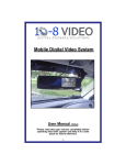
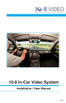
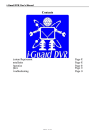
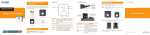
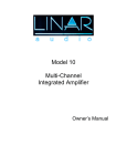
1
Mobile Digital Video System
User Manual (104CF-V3)
Please read this user manual completely before operating this DVR system and keep it in a safe
place for future reference.
Caution!
You, as the driver, are solely responsible for the safe operation of your vehicle and the safety
of your passengers according to the US and local traffic regulations. . Do not use any features
of this system to the extent it distracts you from safe driving. Your first priority while driving
should always be the safe operation of your vehicle. 10-8 Video cannot accept any
responsibility whatsoever for accidents resulting from failure to observe these precautions or
safety instructions:
1. This product utilizes high voltage. Any unauthorized modifications or damage to the
products may result in electrical shock. Handle all components with care. Inspect
regularly for damage to components and cabling.
2. You shall be responsible to ensure that the installation of this product does not void
or affect the vehicle manufacturer’s warranty. 10-8 Video, or
its branches are not liable in full or in part for improper installation resulting in loss
or damage to your property, or for voiding all or part of the vehicle manufacturer’s
warranty.
3. Do not apply excessive force to any of the components contained within this kit.
Excessive force used before, during or after installation that results in a damaged or
non-functional part shall void all warranties.
4. Please follow the procedure from this installation manual. Improper installation or
modification of this product shall void all warranties.
Quick Install Overview
The installation of the 10-8 Patrol Car video system breaks down to some very simple steps. The basic
connection for video and audio are very similar to a VCR or DVD player. The one area that differs from what
you may have done in the past is the connections for the alarm inputs (see separate addendum).
You will need a 12v power source for the system. 10-8 video includes a power distribution block for your
convenience. It simplifies the installation and makes for a cleaner install, since just 1 power and 1 ground will
be needed. We recommend that the power source be from a source that supplies 12v only when the car is on.
The first thing you will want to do is locate where you want to install the DVR. The small size of the unit
makes that much easier than just a few short years ago. If there is no room in the console for a flush mount,
the next areas to consider are on either side of the console, in the dash or under the dash. Try to keep the unit
in site of the driver where they will be able to use the I/R remote more easily. The DVR ships with 2 small
brackets for mounting. Connect the wire harnesses that came with the DVR to their appropriate connections.
The plugs are such that they will only plug into 1 point. Connect the red wire from the transformer to your
power point and black to ground.
Once you have a location for the DVR, locate a convenient spot for the Wireless mic receiver. This will not
have to be readily accessible once it is installed so you may want to put it under a seat, under the dash, in the
trunk, or since it is so light, just Velcro it to the firewall or anywhere else that is convenient for you. It is
recommended that it be in the front ½ of the vehicle for the best reception. Now just run the power and the
audio cables. Run power to your power distribution point and audio to the DVR audio cable labeled #1.
Now mount the mirror/monitor over the existing mirror. A good place to run the wires for the mirror is to tuck
them in the front edge of the headliner and down the passenger side pillar post. The covers on most modern
pillar posts snap in to place and are easily removed with plenty of room. Run the wires down along the door
edge and under the glove box to the location of the DVR. The Mirror will have audio in and video in that will
plug into the back of the DVR unit labeled video out and audio out. The power wires will go to your power
distribution point.
Before you replace the pillar post cover, mount the camera high and just right of center on the windshield.
Once you have located the spot for the camera, push in on the center button of the mount and pull the locking
lever up over the top of the button. This is a very good commercial mount rated for as much as 3lbs and will
hold the camera securely. Now run the included cable along side the mirror/monitor cable to the DVR. Plug
the BNC video connector from the camera to the black video-in cable from the DVR labeled #1. Run the
power lead from the camera to the power distribution point you are using. If you will be using a second
camera for the rear seat area, the video lead from that camera will go to the video-in on the DVR labeled #2.
Basic Wiring Diagram
To: Ground
To: Ign On Power
1. CF Card installation
Insert the CF card Face-up into the CF card slot of the DVR.
2. Audio output connection
Connect audio output to external speaker (Optional).
3. Video connection
Connect the monitor to Video output terminal.
4. Mode 1 or Mode 2 select switch
Mode 1: 2~4 channels sequencing view & record.
Mode 2: Default One channel real time recording. Under Mode 2, it can also work on
switching record in case the sensor wires are used.
5. Audio/Video Input Harness
Black leads are camers 1-4; Red leads are audio 1-2
6. Detecting wire (Sensor control) connection
If you select Mode 2, you can also connect the detecting wire for switching record.
Connect the detecting wire to this socket. Please refer to the following drawing as
for the connecting.
7. Power connection
a. Plug the power cord to Battery Power. Red-Posite/ Black to Ground.
(there is a 5 second delay when power is supplied before DVR will power on)
8. Turn on and use the DVR system
Switch the power switch to “ON”. The DVR is ready to be used.
9. RS-232 signal connection (optional)
Addendum:
Power Distribution Block
The power distribution block is included for your convenience and is not required that you use
it. It makes it easy to power the 4 components in our system with just one power and one
ground from the vehicle. It uses ¼” male spades for the input and ¼” female spades for the
output. Use at your own risk. 10-8 Video is not responsible for it’s use or mis-use. If you
decide to use it, be mindful of polarity with each connection.
Addendum:
Emergency Lights & Manual Switch
Important: When you are setting up the ‘recorder options’, you must go in to the ‘schedule record’ screen
and change all of the ‘c’s to ‘a’s. ‘A’ tells the recorder to record when an alarm triggers. (‘C’ tells the recorder
to record continuously.)
There are 3 leads coming from the sensor harness. Each lead will activate the record function when 12v is
applied. In a typical installation, 2 of these leads will be used. Connect 1 lead to the output side of you control
box for your pursuit lights. This way the recorder will start anytime you are running emergency traffic. The
second lead will be connected to a manual switch that you will activate when you want to start the recorder
without lights activated. You can use the small switch provided or any switch of your choosing that will
provide 12v to the lead.
Many of the newer control boxes will sometimes have a button or switch that is not being used. This is an
excellent choice if available, as it makes for a cleaner install.
TABLE OF CONTENTS
Table of Contents ………………………………………………………………………
1
Introduction ……………………………………………………………………………..
2
Important Safety Information …………………………………………………………
2
Unpacking Your System ………………………………………………………………
3
Control Panel and Function ……………………………………………….………….
4
Installation ………………………………………………………………………………
6
Before Operation ………………………………………………………………………
8
Operation ……………………………………………………………………………….
9
OSD (On Screen Display) Menu Setting Operation Process …………………..
9
Key and function for operation ………………………………………….…………
9
OSD Setting Operation ……………………………………………………………. 12
Title Setup Operation …..………………………….……………………………. 12
Date / Time & Daylight Saving Time Setting ………...………………………… 13
Video Setup …………………………………………….….………….…………. 14
Motion Detect Setting …..…………………….……………...…….….…………. 15
Event List Selection ……………………………………………………………… 16
Auto Sequence Setting ………………………………………………………….
17
Record Setup Operation …………………………….…………………………… 17
System Setup Operation ……………………………...…………………………. 20
Peripheral Setting Operation ……….…………………..……………….………. 23
Key Lock Function Setting Operation …...…………….……………….………. 23
Network Setting Operation ………………...…………………………….………. 24
CF/HDD Lock: ON Function Setting ……...…………………………….………. 24
Play Back Record Data ……..……………………………………………….……….. 25
PTZ Camera Setting and Control ………………………………………….………… 26
PC Player Software Operation ……………………………………………………….. 28
1
INTRODUCTION
Thank you for purchasing our unique 10-8 Video system. To ensure that you realize the full capabilities of
this product, please read this user’s manual before proceeding. Be sure to keep this manual for future
reference in case any problems or questions should arise. We hope you enjoy your new 10-8 system.
IMPORTANT SAFETY INFORMATION
When using your 10-8 equipment, basic safety precautions should always be followed
to reduce the risk of fire, electric shock and personal injury. Please read the followings before using your
equipment:
1. Read and follow all instructions carefully.
2. Follow all warnings and instructions on the product.
3. Unplug the product from the power outlet before cleaning. Do not use liquid cleaners or aerosol cleaners.
Use a damp cloth for cleaning.
4. Do not use this product near water.
5. Do not place this product on an unstable cart, stand or table.
6. Do not allow anything to rest on the power cords. Do not place this product in a location where the
cords can be stepped on or where someone can trip over them.
7. Do not use this product near an area where there is a potential of gas leaks or near any explosive
fumes.
8. Do not place this product near or over a radiator or any other heat source.
9. Use ONLY the included power supply with the system.
10. This equipment is to be opened by ONLY a qualified serviceperson. There are
no user serviceable parts inside. Opening this equipment may expose you to dangerous voltage and other
risks. Incorrect re-assembly of this equipment may result in electric shock.
12. Avoid spilling liquid on this equipment and do not insert any objects through the ventilation slots.
2
UNPACKING YOUR SYSTEM
Your 10-8 system will include the following:
1 x DVR
1 x Remote Control
1 x User’s Manual
1 x Mirror Monitor
1x
Wireless Microphone System
1x
Front View Camera
1x
CF Memory Card (in DVR)
1x
Power Dist. Block
1x
Camera Windshield Mount
3
CONTROL PANEL AND FUNCTION
Front Panel
1.
2.
3.
4.
Power indicator
CF card slot
CF card busy
IR remote control receiver
Rear Panel
5.
6.
7.
8.
Power On/Off switch
Audio output terminal
Video output socket
Mode Switch
9. DC Input socket
10. RS-232 signal to DVR socket
11. Sensor input socket
12. Video/Audio input socket
4
Remote Control
1.
Power On/Off button
2.
Menu button
3.
Record button
4.
PTZ button
5.
Up key (Camera 1)
6.
Down key (Camera 3)
7.
Left key (Camera 2)
8.
Right key (Camera 4)
9.
Select button
10.
Play button
11.
Fast forward button
12.
Fast back button
13.
Pause button
14.
Audio 1 button
15.
Audio 2 button
16.
Audio Mute button
17.
Zoom in button
18.
Zoom out button
19.
PTZ auto button
20.
5
~
Number keys
Installation
DVR Installation
Please refer to the installation process per the following drawing:
1. CF Card installation
Insert the CF card into the CF card slot of the DVR.
2. Audio output connection (optional)
Connect audio output to monitor audio input.
3. Video connection
Connect the monitor to Video output terminal.
4. System Camera installation
Connect one end of camera cable to Camera and the other end to Video Input
#1 terminal at the back of DVR. Please number the camera if using more than 1
camera.
5. Power connection
5-a. Connect the power supply unit to the DVR.
5-b. Plug the power supply to Battery (e.g. car battery).
5-c. Plug the power supply the other wire for Key [On] and key [Start] wire connection
Connect the key on connecting wire (yellow) to car key “ON” position.
Connect the key start wire (white) to car key “Start” position.
6
The power supply with built-in delay circuit board is designed for the DVR to delay
switch-on time for 10 seconds to avoid the DVR working on unstable voltage. It
can also delay switch-off time from 10 minutes to 60 minutes selected by switch
depending on the user requirement.
Switch on/off voltage: 10.5 ~10.8V
Delay switch-on time while starting the car: 10 seconds
Red-Key On Power
Black-Ground
1
Red: Audio In
2
1
2
Black:Video In
3
4
7
BEFORE OPERATION
(1) The system will auto detect the hardware and enter Recording mode while
hardware is in normal condition.
(2) The system will show [UNKNOW HDD] then enter [Format Menu] within 3 seconds
when a new unformatted CF card is inserted. Please select [FORMAT HDD YES]
to format the CF card. The system will auto enter record mode after the CF card
is formatted. (Or, enter the Main menu “record setup” and select HDD
information to format the CF card.)
(3) If the system time has not yet been set, the DVR will display the time setting screen,
please press [MENU](ESC) key to exit after setting the time.
(4) If [NO HD] signal shows on screen, please turn off the power then check that a CF
card is correctly inserted. If yes, please turn the power on again.
(5) If screen shows [NO VIDEO], please check video input connector is
connected correctly to the video camera.
(6) Camera should be on before turning on the DVR unit.
8
OPERATION
The system is preset [KEY LOCK] to [OFF], when the system setting for [KEY LOCK]
mode is [ON], the screen will show:
PASSWORD:
****
Please key in the security code by remote control number keys
OSD (On Screen Display) Menu Setting Operation Process
1. Press [
] to enter menu selection mode.
2. Press up [
3. Press
] key or down [
] key to select the item for setting.
key to enter sub menu to select item for setting.
4. Press Left [
] key or Right [
] key to select the value for your setting.
5. Press
key to exit to previous menu or Press
seconds to exit OSD menu.
key and hold for more than 2
Key and Function for Operation
1 MENU operation key
Key
MENU
(Up Key)
Remarks
Operation
1. Press
key to enter OSD
menu.
2. Press direction key to select.
Enter OSD menu
Go Up
9
3. Press
key to enter sub menu.
4. Press
to exit.
(Down Key)
Go Down
(Left Key)
Go Left
(Right Key)
Go Right
(Enter Key)
ENTER next page
Play operation key
Key
Operation
PLAY
PLAY
FF
FAST FORWARD
FB
FAST BACK
P/S
PAUSE / STOP
REC operation key
Key
REC
Remarks
Operation
Remarks
RECORD
PTZ control key operation (only with PTZ camera installed)
Key
Operation
PTZ
PTZ
IN
ZOOM IN
OUT
ZOOM OUT
Remarks
1. Press
key to enter the
function.
2. Press function key to operate.
3. Press direction to select the area.
Go Up
Go Down
Go Left
Go Right
5 Display operation key
Key
AUTO
Operation
Remarks
Auto sequence view
10
The DVR system is preset to work with one channel. If you want to change it for more
channels, please do the following steps:
When the DVR system is power ON and on record mode,
1. Press FF key two times, FB key two times and
(Select) key two times. Then, the
following screen will be shown. If there are 2 channels or 1 channel selected, then
the other cameras ssetting under MENU will not function.
SELECT CHANNEL MODE
CHANNEL: 1CH
2. Use
3. Press
/
key to select 4CH/2CH/1CH for setting.
key to exit.
On Screen Information::
ACH1 CH01
[REC] 4CH [C][R] 99% 2006/01/01 18:08:08
[ACH1]: Audio in channel 1
[ACH2]: Audio in channel 2
[REC]: Recording
[LIV]: View mode (Without recording)
[BOT]: The DVR system is booting.
[PB]: Playback mode
4CH: 4 channels mode
[C]: Continuous recording
[M]: Motion recording
[A]: Alarm
[R]: Overwriting enabled.
[O]: Overwriting is not allowed.
99%: The percentage of CF card remaining.
11
OSD Setting Operation
1. Title Setup Operation
A. Press
key to enter menu selection mode.
MAIN
TITLE SETUP
DATE/TIME
VIDEO SETUP
MOTION DETECT
EVENT LIST
AUTO SEQUENCE
RECORD SETUP
SYSTEM SETUP
PERIPHERAL SETUP
KEY LOCK:OFF
NETWORK
CF /HDD LOCK: ON
B. Use
/
C. Press
key to select [TITLE SETUP] setting section.
key to enter channel select mode.
TITLE SELECT CH
CH01
CH02
CH03
CH04
D. Use
/
E. Press
key to select channel going setting title.
Key to enter selected channel for title setting.
TITLE SETUP CH01
CH01 : CH01
F. Use
/
key to select alphabet (A~Z) or digital (0~9) for title, maximum 4
alphabet or digits can be setting for one channel title.
G. Press
key to exit for select other channel or press
than 2 seconds to exit OSD setting operation.
12
key and keep more
2. Date / Time & Daylight Saving Time Setting
A. Date/Time Setting
a. Press
key to enter menu selection mode.
b. Use
/
c. Press
key to select [DATE/TIME] setting section.
key to enter [DATE/TIME] setting mode.
DATE/TIME
SETUP DATE/TIME
DAYLIGHT SAVING TIME
d. Press
key to enter [DATE/TIME] setting mode.
SETUP DATE/TIME
YEAR
: 2006
MONTH : 01
DAY
: 01
HOUR
: 18
MIN
: 08
SEC
: 08
MODE: YY:MM:DD
e. Use
/
key to select area for setting.
f. Use
/
key to select value for setting.
g. Press
key to exit for select other setting mode
B. Daylight Saving Time setting
If you want setting daylight saving time, then you can use
saving section and use
key to go daylight
key to turn daylight saving mode on for setting.
13
DAYLIGHT SAVING TIME
TURN: OFF
START TIME
MONTH
DAY
HOUR
END TIME
MONTH
DAY
HOUR
: 04
: 02
: 02
: 04
: 03
: 02
G. Use
/
key to select area for setting.
H. Use
/
key to select value for setting.
I. Press
key to exit for select other setting mode or press
more than 2 seconds to exit OSD setting operation.
3. Video Setup
A. Press
B. Use
key to enter menu selection mode.
/
C. Press
key to select [VIDEO SETUP] setting section.
key to enter [VIDEO SETUP] select mode.
VIDEO SELECT CH
CH01
CH02
CH03
CH04
VIDEO SYSTEM: NTSC (or PAL)
D. Use
E. Press
.
/
key to select channel going setting video.
Key to enter selected channel for video setting
14
key and keep
VIDEO SETUP CH1
BRIGHTNESS: 36 (00~63)
CONTRAST:
36 (00~63)
SATURATION: 36 (00~63)
HUE:
36 (00~63)
APPLY TO ALL
a. Brightness: Brightness is adjustable, “00” = the darkest, “63” = the lightest.
b. Contrast: Contrast is adjustable, “00” = maximum, “63” = minimum.
c. Saturation: Saturation is adjustable, “00” = maximum, “63” = minimum.
d. Hue: Hue is adjustable, “00” = maximum, “63” = minimum.
e. Apply to all: Adjust above items (brightness, contrast, saturation, hue) to the
proper setting and then use the same setting for each camera.
F. Use
G. Use
/
key to select the section.
/
key to select value.
H. Press
key to exit to previous menu or press
than 2 second to exit completely.
key and hold more
4. Motion Detect Setting(Not Used for Patrol Car Installations).
A. Press
B. Use
key to enter menu selection mode.
/
C. Press
key to select [MOTION DETECT] setting section.
key to enter [MOTION DETECT] select mode.
MOTION DETECT SELECT CH
CH01
CH02
CH03
CH04
D. Press
key to enter [CH01] select mode. Or, you can use
select channel going setting video.
E. Use
F.
/
key to select “ON” or “OFF”.
15
/
key to
MOTION DETECTION_CH1
TURN:ON (or OFF)
RELAY OUTPUT: ON (or OFF)
F. Press
key to exit for select other setting mode or press
more than 2 seconds to exit OSD setting operation.
key and keep
5. Event List Selection
A. Press
B. Use
key to enter menu selection mode.
/
key to select [EVENT LIST] setting section.
C. Press
key to enter [EVENT LIST] select mode.
NO
0021
0022
0023
0024
0025
0026
0027
0028
0029
0030
CH
3
4
3
2
1
2
3
4
1
2
EVENT LIST
<PAGE 0003>
STATE YY/MM/DD
HH:MM:SS
A
05 / 08 / 21
15:44:53
A
05 / 08 / 21
15:44:54
A
05 / 08 / 21
15:44:56
A
05 / 08 / 21
15:44:58
L
05 / 08 / 21
15:04:25
A
05 / 08 / 21
15:14:17
A
05 / 08 / 21
15:17:20
A
05 / 08 / 21
15:17:22
A
05 / 08 / 21
15:17:23
A
05 / 08 / 21
15:17:25
* Each page can display 10 events (maximum 1000 events can be recorded).
* The event log will be cleared simultaneously when format CF Card.
* EVENT is recorded in the CF card. It can be searched for playback when the CF
card is removed and installed into the other DVR in same type.
D. Use
E. Press
F. Press
/
key to select event for play.
/
key to change the event list page for select.
Key to play selected event.
G. Press
key to back event list for select other event to play or then press
key to exit event list selection.
16
6. Auto Sequence Setting (For use when more than 1 camera is installed).
A. Press
B. Use
key to enter menu selection mode.
/
key to select [AUTO SEQUENCE] setting section.
C. Press
key to enter [AUTO SEQUENCE] select mode.
AUTO SEQUENCE
CH01: ON CH02: ON CH03: ON
CH04: ON
TIME INTERVAL: 5.0
B. Use
/
key to select channel for auto sequence view.
C. Use
/
key to turn On for view or turn Off for not viewing.
F. Press
/
key to select view each channel time.
G. Use
/
key to select the time to view each channel (0.25 / 0.5 / 0.75 / 1.0 /
1.25 / 1.5 / 1.75 / 2.0 / 2.25 / 2.5 / 2.75 / 3.0 / …… / 10.0).
key to exit for select other OSD setting to set or press
H. Press
seconds to exit OSD setting operation.
7. Record Setup Operation
A. Press
B. Use
key to enter menu selection mode.
/
C. Press
key to highlight [RECORD SETUP] section.
Key to enter [RECORD SETUP] section.
RECORD SETUP:
RECORD MODE CONTINUOUS
ALARM/MOTION HDD INFO
PRE-RECORD
D. Use
/
to select section for setting.
17
key and keep more than 2
E.
Press
Key to enter selected section for setting, then use
/
select the section for setting and use
/
key to
key to select the value.
a. Record Mode set up: 3 record modes For patrol car installations, this section
should be set to all ‘A’s for Alarm Mode.
SCHEDULE RECORD
AM
0
1
2
3
4
5
6
7
8
9
10 11
C
C
C
C
C
C
C
C
C
C
C
C
C
15
C
16
C
17
C
18
C
19
C
20
C
21
C
22
C
23
C
PM
C
C
b. Continuous Record: for set-up 4 level record quality and 6 kinds frame rate for
record.
CONTINUOUS RECORD:
RESOLUTION: CIF
QUALITY:STANDARD
REC RATE:30_FPS
* Resolution: 0.25CIF / CIF / 2CIF
* Quality: Standard / Super / High / Normal.
* REC Rate: Set up frame per second (fps) as below
NTSC: 30 / 15 / 8 / 4 / 2 / 1 (0.25CIF or CIF) or 15 / 12 / 8 / 4 / 2 / 1 (2CIF)
File size
Resolution
720 x 480 (N)
720 x 576 (P)
352 x 244 (N)
352 x 288 (P)
176 x 128 (N)
176 x 144 (P)
Quality
High
Mid
Low
High
Mid
Low
High
Mid
Low
NTSC (K)
21
15
10
7
6
4
4
3
2
(The file size will vary depending on recorded images, above figures are listed for
your reference only.) A good starting point for patrol cars is: 2CIF, 8fps, High
18
c. Alarm / Motion Record: for set-up 4 level record quality, 10 kinds frame rate and
duration for record while detect alarm or motion. A good starting point for patrol
cars is: 2CIF, 8fps, High
ALARM/MOTION RECORD
RESOLUTION: CIF
QUALITY: STANDARD
REC TIME: 60
REC RATE: 30_FPS
SENSITIVITY: 04
* Resolution: 0.25CIF / CIF / 2CIF
* Quality: Standard / Super / High / Normal.
* REC Time: 01~99 (seconds)
* REC Rate: Set up frame per second (fps) as below
NTSC: 30 / 15 / 8 / 4 / 2 / 1 (0.25CIF or CIF) or 15 / 12 / 8 / 4 / 2 / 1 (2CIF)
* Sensitivity: 01 ~ 10 (10 = the highest)
d. HDD information: for show CF Card information.
HDD INFORMATION
CIRCULAR:ON
HDD FORMAT
HDD CAPACITY
USB SLAVE
* If you choose [CIRCULAR: ON], the recorder will continue and overwrite
previous recordings (starting with oldest first) when CF card capacity is full. If you
choose [CIRCULAR: OFF], the recording session stops when all CF card capacity
is full.
* If you select “HDD format”, the CF card will be formatted, erasing all data on the
card.
* It shows the size of the CF card installed in the DVR.
e. USB Slave for back-Up: This function is not available for use CF card model and
USB download port is not built-in.
f. Pre-record setup: Turns on Pre-event recording
PRE-RECORD
PRE-RECORD:ON
REC RATE: 2_FPS
19
* Set “ALARM/MOTION RECORD” mode and then select “PRE-RECORD:
ON”. The system will record 100 images in the hard disk before alarm was
activated.
F Press
key to exit menu or press
seconds to exit.
key and hold more than 2
8. System Setup Operation
A. Press
B. Use
key to enter menu selection mode.
/
C. Press
key to highlight.
key to enter highlighted section.
SYSTEM SETUP:
ALARM IN
PASSWORD
PTZ
AUDIO
DISPLAY
DIALER/GPS
DVR ID
FACTORY DEFAULT
UPDATE CODE FROM HDD
a. Alarm In: To set Alarm functions
ALARM IN
ALARM IN1
ALARM IN2
ALARM IN3
ALARM IN4
ALARM IN1
ALARM IN
:NORMAL CLOSE
RE-ACTION :CH01 (CH01~04)
ALARM OUT :OFF (or ON)
* Normal Close: The signal loop is closed under normal conditions. When the loop
becomes open, alarm will be triggered until the loop becomes closed again. In
other words, if the loop keeps on open for a period of time, alarm will keep on
triggering in that time interval.
* Normal Open: The signal loop is open under normal conditions. When the loop
becomes closed, alarm will be triggered until the loop becomes open again. In
other words, if the loop keeps on closed for a period of time, alarm will keep on
triggering in that time interval. For patrol cars, 2 alarms are generally used: A
manual switch, and 1 for when emergency lights are activated.
20
b. Password: to change password. (defaultl password: 0000)
PASSWORD:
c. PTZ: for setting protocol, baud rate when a pan/tilt/zoom camera is installed
PTZ
PROTOCOL: PELCO_D
BAUD RATE: 9600
* Protocol: PELCO_D / PELCO_P
* Baud Rate: 2400 / 4800 / 9600 / 19200
d. Audio: for turn on or off audio record. Should be set to ‘ON’
AUDIO SETUP
AUDIO REC:ON (or OFF)
e. Display information: to display Channel Name, Record Mode, HDD Mode, HDD
Space, Date and Time on the screen.
DISPLAY
CHANNEL NAME:ON (or OFF)
REC MODE:ON (or OFF)
HDD MODE:ON (or OFF)
HDD SPACE:ON (or OFF)
DATE:ON (or OFF)
TIME:ON (or OFF)
f. Dialer/GPS: (Optional) Not Used
DIALER/GPS
DEVICE: GPS
BAUDRATE: 9600
DIAL MODE: TONE
PHONE 1: _ _ _ _ _ _ _ _ _ _ _ _ _ _ _ _ _ _ _ _
PHONE 2: _ _ _ _ _ _ _ _ _ _ _ _ _ _ _ _ _ _ _ _
PHONE 3: _ _ _ _ _ _ _ _ _ _ _ _ _ _ _ _ _ _ _ _
21
* Device: GPS / DIAL
* Baudrate: 2400 / 4800 / 9600 / 14400 / 19200 / 38400 / 57600 / 115200
* Dial mode: TONE / PULSE
g. DVR ID: for setting DVR ID number. Use for for Car or Officer ID
DVR ID
ID TYPE: ID
ID: 0000
ID TYPE:
h. Factory default: to reset to factory settings..
When you press
Key, the DVR will go back to factory default. The screen
will show “FACTORY DEFAULT OK!”.
i. Update code from CF card: For program
Updates
When you press
Key, the DVR will ask to key in password.
PASSWORD:
After you key in the correct password, it will enter update code from CF Card.
UPDATE CODE
EXIST VER: 01.09RA
RCLT02”01.00
NEW VER: NOFILE
RUN
D. Press
E. Use
/
for setup.
Key to enter the selected section.
key to select section for setting and use
/
key to select value
F. Press
key to exit, or press
key and hold more than 2 seconds to exit OSD
setting operation.
G. When the software is updated, power cycle the DVR from the switch on the back.
22
9. Peripheral Setting Operation
A. Press
key to enter menu selection mode.
B. Use
/
C. Press
key to highlight peripheral setup section.
key to enter [PERIPHERAL SETUP] select mode.
a. Buzzer: Select when you want the audio beep to be activated. We recommend setting ‘ON’ the
‘Alarm In’ section.
PERIPHERAL SETUP
BUZZER:
VIDEO LOSS:ON (or OFF)
MOTION:ON (or OFF)
ALARM IN:ON (or OFF)
KEY MOVE:ON (or OFF)
BEEP TIME:01
Beep Time: 01 ~ 10
D. Use
/
key to select section for setting and use
E. Press
key to exit for other setting or press
second to exit OSD setting operation.
/
key to select value for setup.
key and keep more than 2
10. Key Lock Function Setting Operation
A. Press
B. Use
key to enter menu selection mode.
/
key to select key lock function on or off.
C. Press
/
key to select other section for setting or press
OSD menu setting function.
23
key to exit
11. Network Setting Operation (optional) Not Used..
(This function is available when the DVR is connected with LAN)
A. Press
B. Use
key to enter menu selection mode.
/
key to select “Network” section and press
key to enter for setting.
NETWORK
REMOTE CONNECT: OFF (or ON) RESOLUTION: 2CIF
IP
:000.000.000.000
MASK:000.000.000.000
GATE:000.000.000.000
DNS :000.000.000.000
* Resolution: 0.25CIF / CIF / 2CIF
C. Press
/
key to select other section for setting or press
OSD menu setting function.
key to exit
12. CF / HDD LOCK: ON Function Setting
B. Press
key to enter menu selection mode.
MAIN
TITLE SETUP DATE/TIME VIDEO
SETUP
MOTION DETECTION EVENT LIST
AUTO SEQUENCE RECORD SETUP
SYSTEM SETUP PERIPHERAL SETUP
KEY LOCK:ON/OFF NETWORK
CF /HDD LOCK: ON
B. Use
/
key to select the [CF / HDD lock] on or off.
C. Press
/
key to select other section for setting or press
OSD menu setting function.
24
key to exit
PLAY BACK RECORD DATA
There are four ways to playback the record data.
1. Play begin file: Select this row to play back 1st file.
2. Play end file: Select this row to play back the final file.
3. Playback by date:
Press the “Play” button, the screen will display playback menu, you can use
up/down/right/left/enter buttons to select the start day and time which you want to
play back, then move to “PLAY” and press “Enter” button to playback.
PLAYBACK:
PLAY LATEST FILE
PLAY BEGIN FILE
PLAY END FILE
MINUTE:08
HOUR: 08
DAY:
08
MONTH: 01
YEAR: 2006
PLAY
PLAY BY EVENT
4. Playback by event:
4.1 Press “Play” button, you can select the PLAY BY EVENT from playback menu.
Use up/down/right/left buttons to select event which you want to play back, then
press “Enter” button to playback.
4.2 Press “Menu” button into menu list and select Event list, use
up/down/right/left/enter buttons to select event which you want to play back,
then press “Enter” button to playback.
In the play mode you can use play bar to control play function. The play bar buttons
introduction as below:
FF: fast forward.
Press the “FF’ once the playback speed will change to x2 speed to play, press again
it will change to x4 and press again it will change x8, if you want to return to the
playback speed just press the “Play” button.
FB: fast backward playback.
Press the “FB’ once the backward speed will change to x2 speed to backward play,
press again it will change to x4 and press again it will change x8, if you want to
return to the playback speed just press the “Play” button.
P/S: Pause / Stop button
Pause: Pause the playback. (Press P/S button one time.)
Stop: Stop playback and go back to the view mode. (Press P/S button for longer time)
25
PTZ CAMERA SETTING AND CONTROL
1. Introduction:
Connect the Signal I/O box to the DVR. The signal I/O box has RS485 ports for PTZ
camera control.
2. Installation:
2.1 Setting PTZ camera control protocol:
Follow PTZ camera user manual to choose and setting control protocol, all the camera need to
choose same protocol type.
2.2 Setting PTZ camera ID:
Follow PTZ camera user manual to set PTZ ID, each camera has a unique ID it’s own. We
suggest stronger CH1 camera use the ID no: 1, CH2 camera use the ID no: 2 …, that you will
have more convenience to control your PTZ cameras.
Follow the figure to connect all of cameras RS485 TX together and RX together, then insert RS485 TX
into the RS485 TX terminal and RX insert into the RS485 RX terminal and tight it.
3. PTZ control setting:
3.1 Go to DVR menu and select system, into system list and select subject of PTZ/Keyboard,
then use left and right keys to select protocol to match your PTZ camera setting.
3.2 Use up and down keys to select subject of baud-rate, then use left and down keys to select baudrate to match your PTZ camera setting.
3.3 Use up and down keys to select subject of ID, then use left and down keys to select ID to match
witch PTZ camera you want control now.
3.4 If you want to set auto pan, you can select auto pan=on. Go to auto-pan setup and use
up/down/right/left keys to set the start point and end point. Press cam1 save right position, cam2
save left position and press cam3 demo auto pan, and then use Menu key to quit PTZ setting.
3.5 Example:
PTZ
Protocol: Pelco P Baud rate: 9600 bps
ID: 1
Auto pan: on
26
4. PTZ control:
How to move PTZ camera?
The process is as follows:
1. Press PTZ button.
2. Select Channel to control.
3. Press Up key to move camera up.
4. Press Down key to move camera down.
5. Press Left key to move camera left.
6. Press Right key to move camera right.
7. At any time press Stop key to stop camera move.
8. Press Auto key to turn the auto pan on.
9. Press PTZ key to quit PTZ control mode.
PC PLAYER SOFTWARE OPERATION
Install the 10-8 Player software by installing the CD supplied with your
system. Is the CD is not available, you may download it from the 10-8
video web site by entering the following address in your browser:
http://www.10-8video.com/dvr/dvr.exe
This will download the player to your computer. When asked, select ’run’
and the software will install. Double click on the 10-8 player icon to load
the player.
If a box appears asking for a password, just hit the enter key or clik on
‘OK’. You may assign a password later in the program.
27
3. How to play a recording:
(1) Click on ‘Open New File’ Button
(2) Click on Browse and select the file location. If the files are already on the
hard drive, just select the location or if on a CF card, select the drive letter
associated with your card reader.
28
(3) Select the file by click on file with a .DVR extension and then selecting
‘Open’. Select the file on the next screen and select ‘Open’ to play. Or select
‘Search All Event’ to bring up a screen with all events that were recorded
sorted by date and time.
Select the event you wish to play and select ‘Open’.
29
You will now be in the main player screen ready to play your video. Press
the large ‘PLAY’ button to begin the video.
Clicking on the speaker icon will mute the audio. Click again to un-mute
the audio and use the sliding volume control and your speaker volume to
adjust the volume. Clicking on the ‘On Screen Display’ button will turn the
date/time display on the video on and off.
.
The Play speed adjustment panel works similar to a DVD or VCR panel. You
can speed up, slow down, and view frame by frame with this panel. You can
also use the slider button under the video to quickly go forward or backward in
the video. The 2 arrows on either side of the pause button will play the video in
slow motion. Repeated use of the pause button will advance frame by frame.
Pressing the ‘Save to JPEG’ button will save the current frame in the display to
a common .jpg file on your hard drive.
The ‘Create Media File’ button will allow you to save to .avi and .wmv files.
Note however that the .avi files are quite large and the wmv files do not
currently have audio. The preferred method of saving files is the ‘Copy
File TO PC’. This will kept the quality at the best resolution and the file
will be saved in it’s native proprietary format.
Before using the ‘Copy File to PC’ option, make a note of the beginning and
end times of the event of video you wish to save. Then select the option to
open to the following screen:
‘Copy File To PC’:
30
Select the path and file name you want the video saved to. Be sure and leave the
.DVR extension on the file.
Move the slider to the time in the video you wish to begin recording and then
select the ‘Set time’ button next to the Start time window. For finer adjustment,
use the left and right arrow buttons. Move the slider to the time that you wish to
set for the end of the video and select ‘Set time’ button on the End Time line.
Once the start and end times are correct, select the ‘Copy file to PC’ button to
save the file.
31