1
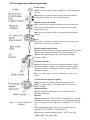
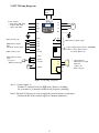
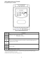
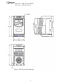
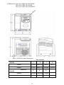
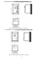
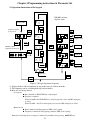
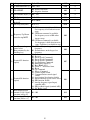
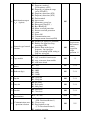
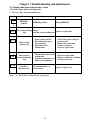
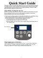
Quick Start Guide
This guide is to assist in installing and running the inverter to verify that the drive and motor
are working properly. Starting, stopping and speed control will be from the keypad. If your
application requires external control or special system programming, consult the 7300EV
Instruction Manual supplied with your inverter.
Step 1 Before starting the inverter
Please refer to chapter one (Notice for wiring) of the 7300EV Instruction Manual. If you feel
this was abnormal, do not start the drive until qualified personnel have corrected the
situation. (Failure to do so could result in serious injury.)
• Check inverter and motor nameplates to determine that they have the same HP and voltage
ratings. (Ensure that full load motor amps do not exceed that of the inverter.)
• Remove the terminal cover to expose the motor and power terminals.
a. Verify that AC power is wired to L1(L), L2, and L3(N) .
b. Verify that Motor leads are connected to T1, T2, and T3 .
c. IF brake module is necessary, please connect terminal voltage of the braking unit to +
and - of the inverter.
Power Indicator
Step2 Apply power to the drive.
Apply AC power to the drive and observe operator. Three 7-segment display should show
power voltage for 3~5 seconds and then show Frequency Command, factory sets 5.00.
(Frequency Command of 7-segment display should be flashed all the time.)
1
Step3 Check motor rotation without load.
Press RUN Key. 7-segment Display will indicates 00.0to 05.0. Such value is the frequency
output value.
Check the operation direction of the motor.
IF the direction of the motor is incorrect:
Press STOP Key, turn off the AC power supply. After Power indicator LED is off,
change over theT1 and T2.
Supply the power again, then check the motor direction.
Press STOP key.
Step4 Check full speed at 50Hz/60Hz
Change the frequency with ,
arrow mark , please press DATA/ENTER after setting
frequency.
Set frequency to 50Hz/60Hz according to the above regulations.
Press RUN Key, inspect the motor operation as motor accelerates to full load.
Press STOP Key, inspect the motor operation as motor deceleration.
2
CONTENTS
Quick Start Guide ....................................................................................................... 2
Chapter 1 Notice for wiring ........................................................................................ 4
1.1 Fuse types........................................................................................................... 4
1.2 Precautions for peripheral applications ............................................................... 5
1.3 EV Wiring diagram ............................................................................................. 6
1.4 Descriptions of Inverter terminal.......................................................................... 7
1.5 Dimensions ....................................................................................................... 10
Chapter 2 Programming instructions & Parameter list ......................................... 13
2.1 Operation Instruction of the keypad................................................................... 13
2.2 Parameter function list....................................................................................... 14
Chapter 3 Troubleshooting and maintenance ....................................................... 21
3.1 Trouble indication and corrective action ............................................................ 21
3.1.1 Fault/Error display and Diagnostics .......................................................... 21
3.1.2 Set up configuration, Interface errors........................................................ 24
3.1.3 Keypad operation error description ........................................................... 25
3.2 General functional troubleshooting ................................................................... 26
3
Chapter 1 Notice for wiring
1.1 Fuse types
Drive input fuses are provided to disconnect the drive from power in the event that a component fails in the drive’s
power circuitry. The drive’s electronic protection circuitry is designed to clear drive output short circuits and ground
faults without blowing the drive input fuses. Below table shows the EV input fuse ratings.
To protect the inverter most effectively, use fuses with current-limit function.
RK5, CC/T type fuse for EV
110V class(1φ)
HP
KW
KVA
1P2-H1
0.25
0.2
0.53
100% CONT
Output AMPS (A)
1.7
1P5-H1
0.5
0.4
0.88
3.1
15
30
101-H1
1
0.75
1.6
4.2
20
40
HP
KW
KVA
2P2-H1
0.25
0.2
0.53
100% CONT
Output AMPS (A)
1.7
2P5-H1
0.5
0.4
0.88
3.1
10
20
201-H1
1
0.75
1.6
4.2
15
30
202-H1
2
1.5
2.9
7.5
20
40
203-H1
3
2.2
4.0
10.5
25
50
HP
KW
KVA
2P2-H3
0.25
0.2
0.53
100% CONT
Output AMPS (A)
1.7
2P5-H3
0.5
0.4
0.88
3.1
8
10
201-H3
1
0.75
1.6
4.2
12
15
202-H3
2
1.5
2.9
7.5
15
20
203-H3
3
2.2
4.0
10.5
20
30
HP
KW
KVA
401-H3
1
0.75
1.7
100% CONT
Output AMPS (A)
2.3
402-H3
2
1.5
2.9
3.8
10
15
403-H3
3
2.2
4.0
5.2
10
20
JNEV-
FUSE
Max.RK5
Max.CC or T
Rating(A) FUSE Rating(A)
10
20
220V class(1φ)
JNEV-
FUSE
Max.RK5
Max.CC or T
Rating(A) FUSE Rating(A)
8
15
220V class(3φ)
JNEV-
FUSE
Max.RK5
Max.CC or T
Rating(A) FUSE Rating(A)
5
8
440V class(3φ)
JNEV-
FUSE
Max.RK5
Max.CC or T
Rating(A) FUSE Rating(A)
6
10
*Fuse ratings are based upon 300V fuses for 120V inverters, and 300V fuses for 230V
inverters, and 500V for 460V inverters
4
1.2 Precautions for peripheral applications:
Power supply:
Make sure the correct voltage is applied to avoid damaging the
inverter.
A molded-case circuit breaker or fused disconnect must be
installed between the AC source and the inverter.
Molded-case circuit breaker:
Use a molded-case circuit breaker that conforms to the rated
voltage and current of the inverter to control the power and
protect the inverter.
Do not use the circuit breaker as the run/stop switch for the
inverter.
Fuse:
A suitable fuse should be installed with inverter rated voltage and
current when a MCCB is not being used.
Earth Leakage circuit breaker:
Install a leakage breaker to prevent problems caused by current
leakage and to protect personnel. Select current range up to
200mA, and action time up to 0.1 second to prevent high
frequency failure.
Magnetic contactor:
Normal operations do not need a magnetic contactor. When
performing functions such as external control and auto restart
after power failure, or when using a brake controller, install a
magnetic contactor.
Do not use the magnetic contactor as the run/stop switch for the
inverter.
AC Line Reactor for power quality:
When inverters are supplied with high capacity (above
600KVA) power source, a AC reactor can be connected to
improve the PF.
Input noise filter:
A filter must be installed when there are inductive loads
affecting the inverter.
Inverter:
Output terminals T1, T2, and T3 are connected to U, V, and W
terminals of the motor. If the motor is reversed while the inverter
is set to run forward, just swap any two terminals of T1, T2, and
Figure 1-1 Typical installation
T3.
schematic
To avoid damaging the inverter, do not connect the input
terminals T1, T2, and T3 to AC input power.
Connect the ground terminal properly.( 230 V series: Rg
<100Ω; 460 V series: Rg <10Ω.)
5
1.3EV Wiring diagram
Braking
Unit
Power terminal
• Single phase 100~120V
• 1/3 phase 200~240V
• 3 phase 380~480V
PNP common point
L1(L)
T1
L2*
T2
L3(N)
T3
PE
PE
(3)24V
RA(1)
(4)S1
RB(2)
Multi function digital
input
Accept DC 12/24V signal
(5)S2
NPN common point
(8)COM
Multi-function analog
input
• Set speed
• PID feed back input
IM
Multi-function digital output
(6)S3
1.SW1: Digital signal selection (NPN/PNP)
2.SW2: Control signal selection
(0~10V/4~20mA) V/I
(7)S4
21
(9) 10V
10k
(10)AIN
(11)COM
FM
• Option interface
• Multi-function output
S5
S6
(12)FM+
T+
input card
(2 IN/ 1 out)
• Remote keypad
T24V/0.6A
Figure 1-2 Wiring diagram
Note 1:- Connect inputs to
Terminal 3 ( internal 24vdc) for PNP mode ( Positive switching) .
Or to terminal 8 ( Common) for NPN mode( Negative switching) .
Note2:- External 24 Vdc may be used to supply the external contacts at each input
(Connect the 0V of the external supply to Common (terminal 8).)
6
7
1.4 Description of Inverter Terminal
Descriptions of power terminals
Figure 1-3 Power terminals locations
Symbol
L1 ( L )
L2
Description
Main power input Single-phase: L/N*
Three-phase: L1/L2/L3
L3 ( N )
⊕
DC power and braking unit connection terminals. (match with braking units and
braking resistor to brake)
T1
T2
Inverter output
T3
PE
Grounding terminals (2 points)
* Braking units are required for applications where a load with high inertia needs to be stopped rapidly.
Use a power-matched braking unit and resistor to dissipate the energy generated by the load while stopping.
Otherwise inverter will trip on over voltage.
* Terminal at L2 will be non-functional for single-phase units.
8
Control signal terminals block description
1 2 3 4 5 6 7 8 9 10 11 12
TM2
FM+
COM
AIN
10V
COM
S4
S3
S2
S1
24V
RB
RA
Figure 1-4 Signal terminal locations
Symbol
Description
RA
RB
Rated contact capacity:
Multi-functional output terminal
Normally open contact
(250VAC/10A)
Contact description: (refer to
parameter F21)
10V
Supply for external potentiometer for speed reference.
AIN
Analog frequency signal input terminal or multi-function input terminal S7 (high
level : 8V/low level: 2V), adaptable to PNP (refer to parameter F15 description)
24V
PNP (SOURCE) input, S1~S4 (S5/S6/S7) common terminal, (set SW1 to PNP
and connect option card power.)
COM
NPN (SINK) input, S1~S4 (S5/S6) common terminal, (set SW1 to NPN, and
analog input, connect option card power, output signal common terminal.)
FM+
Multi-function analog output + terminal (refer to parameter F26description),
output signal: DC 0-10V.
Symbol
Description
S1
S2
S3
Multi-function input terminals (refer to parameters F11~F14 description)
S4
9
SW function description
SW1
Type of external signal
Remarks
NPN input (SINK)
PNP input (SOURCE)
SW2
Type of external signal
Factory default
Remarks
V
0~10V DC analog signal
I
Effective when parameter
F05=2 (analog input
signal from TM2)
V
I
4~20mA analog signal
10
11
1.5 Dimension
(1) IP20 Frame1: Single phase: JNEV-1P2~201-H1/H1F
Three phase: JNEV-2P2~201-H3
Figure 1-5 EV Drive frame1 Dimensions
12
(2) IP20 Frame2: Single phaseJNEV-202~203-H1/H1F
Three phase JNEV-202~203-H3
Three phase JNEV-401~403-H3/H3F
Figure 1-6 EV Drive frame2 Dimensions
Unit: inch/mm
MODEL
LENGTH
A
B
Frame 1
5.2/132
4.86/123.5
2.64/67
3.03/77
Frame 2
5.2/132
4.86/123.5
4.25/108
4.65/118
E
F
G
LENGTH
MODEL
Frame 1
Frame 2
5.13/130.5 5.06/128.45
5.83/148
13
5.67/144
C
0.315/8
0.315/8
D
(3) IP65 Frame1(switch) EV-1P2/1P5/101/2P2/2P5/201-N4S(IP65 type):
type):
Figure 1-7 EV Drive IP65 (switch) Frame 1 dimensions
IP65 Frame1(no switch) EV-1P2/1P5/101/2P2/2P5/201-N4(IP65 type):
type):
Figure 1-8 EV Drive IP65 (no switch) Frame 1 dimensions
14
Chapter 2 Programming instructions & Parameter list
2.1 Operation Instruction of the keypad
F10=001, inverter
displays status
F×
Power ON
Frequency display
in stop mode
V
DSP
FUN
VALUE
RUN
STOP
VALUE
DSP
FUN
^
DATA
ENT
DC voltage
VALUE
Output current
V
˙
Output voltage
DSP
FUN
××
DSP
FUN
DATA
ENT
DSP
FUN
DATA
ENT
Blinking output
frequency in run mode
˙ ~
DATA
ENT
F×
˙
RUN
STOP
^
DSP
FUN
××
DATA
ENT
DATA
ENT
VALUE
PID Feedback
After 0.5s
DSP
FUN
DSP
FUN
Figure 2-1 Keypad Operations Sequence
*1: Display flashes with set frequency in stop mode, but it is solid in run mode.
*2: The frequency can be set during both stop and run modes.
Remote/Local change function
• Local mode
●Run command via RUN/STOP key on the keypad
●Frequency command
When C41=000: only UP/DOWN key on the keypad can control and F05 setting has
no effect.
When C41=001: only VR on the keypad can control and F05 setting has no effect.
• Remote mode
●Run command from Run parameter (F04) control setting
●Frequency command from Frequency parameter (F05) control setting
•Remote/Local change mode on keypad is achieved by simultaneously pressing ▼/RESET and
15
DATA/ENT. Each successive operation toggles between local and remote.
Note: The inverter must be stopped.
16
2.2 Parameter function list
Basic parameter function list
Factory
Default
Remarks
Inverter horse power
capacity
01 Acceleration time 1
02 Deceleration time 1
05.0
05.0
*1 *2
*1 *2
03
000
*1
F
Function Description
Range/ Code
00
04
05
06
07
08
09
10
00.1~999s
00.1~999s
000: Forward
Motor rotation direction
001: Reverse
000: keypad
Run command source
001: External Terminal
002: Communication Control
000: UP/Down Key on control panel
001: Potentiometer on control panel
002: AIN input signal from ( TM2)
Frequency command source 003: Multi-function input terminal
UP/DOWN function
004: RS-485 Communication
frequency setting
000: Forward/ Stop-Reverse/Stop
External control operation
001: Run/ Stop-Forward/Reverse
mode
002:3-wire—Run/ Stop
Frequency upper limit
01.0 ~200Hz
Frequency lower limit
00.0 ~200Hz
000: Decelerate to stop
Stopping method
001: Coast to stop
000: No display
Status display parameters
001: Display
11 Terminal S1 Function
12 Terminal S2 Function
13 Terminal S3 Function
14 Terminal S4 Function
15 Terminal AIN Function
000: Forward
001: Reverse
002: Preset Speed Command 1
003: Preset Speed Command 2
004: Preset Speed Command 3
005: Jog frequency Command
006: Emergency stop(E.S.)
007: Base Block (b.b.)
008: Select 2nd accel / decel time
009: Reset
010: Up command
011: Down command
012: Control signal switch
013: Communication control signal switch
014: Acceleration/deceleration prohibit
015: Master/Auxiliary speed source select
016: PID function disable
017: Analog frequency signal input(
terminal AIN)
018: PID feedback signal (terminal AIN)
019: DC Brake signal
000
000
000
50.0/60.0
00.0
000
000
*1
000
001
005
006
017
16 AIN signal select
000: 0~10V(0~20mA)
001: 4~20mA(2~10V)
000
17 AIN Gain (%)
000~200
100
17
*2
*2
*1
18 AIN Bias (%)
19 AIN Bias
20
AIN Slope Direction
000~100
000: Positive
001: Negative
000: Positive
001: Negative
000: Run
001: Frequency reached
(Set frequency ± F23)
000
*1
000
*1
000
*1
002: Frequency is within the range
set by (F22±F23)
21
22
23
24
25
26
27
28
29
003: Frequency Detection (>F22)
004: Frequency Detection (<F22)
005: Fault terminal
Multi-function output RY1 006: Auto reset and restart
007: Momentary power loss
008: Emergency Stop(E.S.)
009: Base Block (b.b.)
010: Motor overload protection
011: Inverter overload protection
012: retain
013: Power On
014: Communication error
015: Output current detection(>F26)
Output frequency at
00.0~200
the Set value (Hz)
Frequency detection range
00.0~30.0
(±Hz)
Output current set value
000~100%
Output current detection
00.0~25.5(Sec)
time
000: Output frequency
001: Set frequency
Multi-function output
002: Output voltage
analog type selection
003: DC voltage
(0~10Vdc)
004: Output current
005: PID feedback signal
Multi-function analog
000~200%
output gain (%)
Preset frequency 1 (Main
00.0~200Hz
frequency setting)
Preset frequency 2
00.0~200Hz
000
00.0
*1
00.0
*1
000
00.0
000
*1
100
*1
05.0
*1
05.0
*1
30 Preset frequency 3
31 Preset frequency 4
00.0~200Hz
00.0~200Hz
10.0
20.0
*1
*1
32
33
34
35
36
37
00.0~200Hz
00.0~200Hz
00.0~200Hz
00.0~200Hz
00.0~200Hz
00.0~25.5 Sec
30.0
40.0
50.0
60.0
05.0
00.5
*1
*1
*1
*1
*1
38 DC braking start frequency 01.0~10.0 Hz
01.5
Preset frequency 5
Preset frequency 6
Preset frequency 7
Preset frequency 8
Jog frequency instruction
DC braking time
18
39 DC braking level
40 Carrier frequency
005
010
41
000
42
43
44
45
46
47
48
49
50
51
52
53
54
000~020%
004~016
000: Enable
Auto Restart for power-loss
001: Disable
000~005
Auto-restart times
Motor rated current
Motor rated voltage
Motor rated frequency
Motor rated power
Motor rated speed
Torque Boost Gain (Vector) 001~450
Slip Compensation Gain
001~450
(Vector)
Low frequency voltage
000~40
compensation
Advanced parameter
000: don’t display
function display
001: display
010: Reset to factory default (50Hz)
Factory default
020: Reset to factory default (60Hz)
Software version
CPU Version
Latest 3 fault records
4~16K
000
*4
*4
*4
*4
*4
000
*1
000
*3 *4
*3 *4
Advanced function parameter list(Enable access to these parameters by setting F51=001)
C
Function Description
00 Reverse run instruction
Acceleration stallprevention
Acceleration stall02
prevention level (%)
Deceleration stall03
prevention
Deceleration stall04
prevention level (%)
01
05 Run stall-prevention
Run stall-prevention
level (%)
Stall prevention time
07
during run
Stall prevention
08
deceleration time set
06
09 Direct start on power up
10 Reset mode
Range/ Code
000: Reverse enable
001: Reverse disable
000: Acceleration stall prevention enable
001: Acceleration stall prevention disable
Factory
default
000
000
050 - 200
200
000: Deceleration stall prevention enable
001: Deceleration stall prevention disable
000
050 - 200
200
000: Run stall prevention available
001: Run stall prevention unavailable
000
050 - 200
200
000: according to decel time set in F02
001: according to decel time set in C08
000
00.1 – 999 Sec
03.0
000: Direct start available
001: Direct start disabled
000: RUN instruction is OFF, Reset
command is available.
001: Whether RUN instruction is OFF or
ON, Reset command is available.
19
001
000
Remarks
11 Acceleration time 2
00.1~999 Sec
05.0
*1 *2
12 Deceleration time 2
00.1~999 Sec
05.0
*1 *2
This function
only available
for IP20 type,
For IP65
type , fan will
run while
power is on.
000: Auto-run at set temperature
13 Fan control
14 Control mode
001: Run when inverter runs
002: Always run
003: Always stop
000:Vector control
001:V/F Control
001 ~ 007
15 V/F Pattern setting
V/F base output voltage
16
198~265V / 380~530V
set
Max output frequency
17
00.2 – 200
(Hz)
Output voltage ratio at
18
00.0 – 100
max frequency (%)
19 Mid frequency(Hz)
20
21
22
23
24
Output voltage ratio at
mid frequency (%)
Min output frequency
(Hz)
Output voltage ratio at
Min frequency (%)
Torque Boost Gain
(V/F)
Slip Compensation Gain
(V/F)
001
000
*4
001/004
220/440
50.0/60.0
100
00.1 – 200
25.0/30.0
00.0 – 100
50.0
00.1 – 200
00.5/00.6
00.0 – 100
01.0
00.0 ~ 30.0%
00.0
*1
00.0 ~100%
00.0
*1
Varies with
motor rating *4
25 Motor no load current
Electronic thermal relay 000: Enable motor protection
26 protection for motor
001: Disable motor protection
(OL1)
000
27 Skip frequency 1(Hz)
00.0~200
00.0
*1
28 Skip frequency 2(Hz)
00.0~200
00.0
*1
Skip frequency range
(±Hz)
00.0~30.0
00.0
*1
29
31 PID Error gain
000: PID Function unavailable
001: PID control, Bias D control
002: PID Control, Feedback D control
003: PID Control, Bias D reverse
characteristics control.
004: PID Control, Feedback D reverse
characteristics control.
0.00 – 10.0
1.00
*1
32 P: Proportional gain
0.00 – 10.0
01.0
*1
30 PID operation mode
20
000
33 I: Integral time (s)
00.0 – 100
34 D: Differential time (s) 0.00 – 10.0
10.0
0.00
*1
*1
000
*1
36 PID OFFSET adjust (%) 000 – 109
000
*1
37 PID Update time (s)
PID Sleep mode
38
threshold
00.0 - 02.5
00.0
*1
00.0~200Hz
00.0
00.0~25.5
00.0
35 PID OFFSET
39 PID Sleep delay time
40
41
42
43
44
45
000: Positive direction
001: Negative direction
000: UP/Down command is available.
Set frequency is held when inverter
stops.
001: UP/Down command is available.
Frequency Up/ Down
Set frequency resets to 0Hz when
control using MFIT
inverter stops.
002: UP/Down command is available.
Set frequency is held when inverter
stops. Up/Down is available in stop.
Local/Remote frequency 000: UP/Down key on keypad sets
control select
frequency
(Run command by the 001: Potentiometer on the keypad set
Run/Stop key)
frequency
000: Forward
001: Reverse
002: Preset Speed Command 1
003: Preset Speed Command 2
004: Preset Speed Command 3
Terminal S5 function
005: Jog Frequency Command
(option)
006: Emergency Stop(E.S.)
007: Base Block
(b.b.)
008: Select 2nd accel/decel time.
009: Reset
010: Up Command
011: Down Command
012: Control signal switch
013: Communication control signal
switch
014: Acceleration/ deceleration disable
Terminal S6 function
015: Master/auxiliary speed source select
016: PID function disable
(option)
017: Analog frequency signal input(
terminal AIN)
018: PID feedback signal (terminal AIN)
019: DC Brake signal
Multi-function input
terminal S1~S6 signal 001~100
scan time (mSec ×8)
Confirming AIN signal
001~100
scan time (mSec x 8 )
21
000
000
007
009
010
050
46
000: Run
001: Frequency reached
(Set frequency ± F23)
002: Frequency is within the range
set by (F22±F23)
003: Frequency detection (>F22)
004: Frequency detection (<F22)
005: Fault terminal
006: Auto-restart
Multi-function output
007: Momentary power loss
T+, T- (option)
008: Emergency Stop(E.S. )
009: Base Block(b.b.)
010: Motor overload protection
011: Inverter overload protection
012: retain
013: Power ON
014: Communication error
015: Output current detection(>F26)
000: Disable (no signal loss detection)
001: Enable. On signal loss Stop
according to F09
Remote keypad control
002: Enable. Runs at the last set
selection
frequency. On signal loss
Stop is according to F04 setting or
Stop key on keypad.
000: Copy module disable
001: copy to module from inverter
Copy module
002: copy to inverter from module
003: read/ write check
Inverter communication
001 ~ 254
address
000: 4800
001: 9600
Baud rate (bps)
002: 9200
003: 38400
000: 1 Stop bit
Stop bit
001: 2 Stop bit
005
000
Stop inverter
then connect
remote
keypad for
proper
operation *4
000
*3
001
*3 *4
003
*3 *4
000
*3 *4
52 Parity bit
000: No parity
001: Even parity
002: Odd parity
000
*3 *4
53 Data bits
000: 8 bits data
001: 7 bits data
000
*3 *4
00.0 ~ 25.5 Sec
00.0
*3*5
000
*3*5
47
48
49
50
51
54
55
Communication error
detection time
000: Deceleration to stop.
(F02: Deceleration time 1).
Communication error 001: Coast to stop.
operation selection 002: Deceleration to stop.
(C12: Deceleration time 2).
003: continue operating.
22
Note: *1: Can be modified in Run mode.
*2: Frequency resolution is 1Hz for settings above 100 Hz.
*3: Cannot be modified during communication.
*4: Do not change while making factory setting.
F52 factory setting is 020(60HZ) and motor parameter value is 170.
F52 factory setting is 010(50HZ) and motor parameter value is 140.
*5: Available in Software version 1.2 or later
23
Chapter 3 Troubleshooting and maintenance
3.1 Trouble indication and corrective action
3.1.1 Fault/ Error display and Diagnostics
1. Un- reset able / un recoverable Errors
Display
EPR
Error
EEPROM
problem
Cause
EEPROM problem
Corrective Action
Change EEPROM
@
OV
Over voltage during Voltage
Repair or replace unit
stop
Detection circuit malfunction
@
LV
Under voltage
during stop
@
OH
CTR
1. Power voltage too low
2. Restraining resistor or
fuse burnt out.
3. Detection circuit
malfunctions
1. Check if the power voltage is
correct or not
2. Replace the restraining
resistor or the fuse
3. repair or replace unit
1. Thermal Detection circuit
The inverter is
1. Repair or replace unit
malfunction
overheated during
2. Improve ventilation conditions
2. Ambient temperature too
stop
or relocate inverter
high or bad ventilation
Current
transducer
detection error
Current transducer or
circuit error.
Note: “@” the Failure contact does not operate.
24
Repair or replace unit
2. Errors which can be recovered both manually and automatically
Display
Error
Cause
Corrective Action
1.Motor winding and
1.Check the motor
frame short circuit
2.Check the wiring
2.Motor and ground short circuit
3.Replace the power module
3.Power module is damaged
OCS
Over current at
start
OCD
Over-current at The preset deceleration time is
deceleration too short
OCA
OCC
OVC
OHC
Set a longer deceleration time
1. Acceleration time is too short
2. The capacity of the motor is
1. Set a longer acceleration time
higher than the capacity of the 2. Replace the inverter with the
inverter
same or greater capacity as
Over-current at
3.Short circuit between the motor that of the motor
acceleration
winding and frame.
3. Check the motor
4.Short circuit between motor 4. Check the wiring
wiring and earth
5. Replace the IGBT module
5. IGBT module is damaged
Over-current 1. Transient load change
during run 2. Transient power change
Increase inverter capacity
1. Set a longer deceleration time
Over voltage
2. Add a braking resistor or
1. Deceleration time setting is too
during
braking unit
short or excessive load inertia
operation/
3. Add a reactor at the input
2. Power voltage varies widely
deceleration
line side
4. Increase inverter capacity
1. Check if there are any
problems with the load
High heat sink 1. Heavy load
2. Increase inverter capacity
temperature 2. Ambient temperature too high
3. Improve ventilation
during
or bad ventilation
conditions
operation
4. Inspect the setting value of
parameter C13
25
3. Errors which can only be recovered manually (no auto-restart)
Display
OC
OL1
Error
Over-current
during stop
Motor overload
Cause
1. OC Detection circuit
malfunction
2. Bad connection for CT
signal cable
Corrective Action
Send the inverter back for
repair
1. Increase motor capacity
1. Heavy load
2. Improper settings of F43
2. Set F43 correctly according
to motor nameplate.
OL2
Inverter overload Excessively Heavy load
Increase inverter capacity
LVC
1. Power voltage too low
Under voltage
2. Power voltage varies
during operation
widely
1. Improve power quality.
2. Set a longer acceleration time
3. Add a reactor at the power
input side
4. Contact technical support
Note: “@” means when the inverter fails, the failure contact does not activate.
26
3.1.2 Set up Configuration, Interface Errors.
Display
SP0
Error
Description
Zero speed stop Set frequency is <0.1Hz Increase set frequency
SP1
Fail to start
directly
1. If the inverter is set to external control mode (F04=001), and
direct start is disabled (C09=001), the inverter cannot be
started and will flash STP1 when the Run switch is ON when
applying power (see descriptions of C09).
2. Direct start is possible when C09=000.
1. If the inverter is set to external control mode (F04=001), the
inverter will stop according to the setting of F9 when the
stop key is pressed. STP2 flashes after stop. Turn the Run
switch to OFF and then ON again to restart the inverter.
SP2
E.S.
2. If the inverter is in communication mode and Stop key is
Keypad
enabled, the inverter will stop in the way set by F9 when
emergency stop
Stop key is pressed during operation and then flashes STP2.
The PC has to send a Stop command then a Run command
to the inverter for it to be restarted.
The inverter will decelerate to stop and flashes E.S. when there
External
is an external emergency stop signal via the multi-function
emergency stop
input terminals(see descriptions of F11~F14).
b.b.
External base
block
The inverter stops immediately and then flashes b.b. when
external base block is input through the multi-functional input
terminal (see descriptions of F11~F14).
PID
PID feedback
signal loss
PID feedback signal circuit error detection
———
1. When REMOTE KEYPAD does not connect with inverter,
this signal will be displayed on the Remote keypad.
REMOTE
2. When REMOTE KEYPAD connects with inverter, this
KEYPAD cable
signal will be displayed on the main keypad.
broken
3. When both REMOTE KEYPAD and main KEYPAD display
this signal means communication errors.
27
3.1.3 Keypad operation error description
Display
Er1
Er2
Er5
Er6
Er7
EP1
EP2
Error
Cause
1. Attempt to Press▲ or ▼
keys when F05> 0 or in
speed operation.
Key operation 2. Attempt to modify
error
parameters, which can not
be modified during Run
(see parameter list).
Parameter
setting error
1. F07 is within ranges of
C27±C29or C28±C29
2. F07<F08 or F07=F08
1.Issue a control command
Modification of
during communication
parameter is not
disabled
allowed during
2. Modify C49~C53 during
communication
communication.
Corrective Action
1. ▲ or ▼ keys can be used
to modify frequencies only
when F05=0.
2. Modify parameters only
in stop mode.
1. Modify F32~F33
2. 3-00>3-01
1. Issue the enabling
command before while
communicating.
2. Set up parameters before
communicating.
1. Incorrect wiring.
2. Incorrect settings of
1. Check the hardware and
Communication
communication parameters.
wiring.
failure
3. Check-sum error.
2. Check C49~C53
4. Incorrect communication
verification.
Incorrect
parameter
settings
1. Attempt to modify F00
2. Voltage and current
detection circuits are
malfunctioning.
1. Set C48=1.2, can not
connect with Copy Unit.
Parameter set 2. Copy Unit failure.
error, Copy Unit 3. The voltage and drive
rating on Copy Unit & the
failure
inverter are different.
Copy the parameter to
inverter to verify the
Parameters do
parameter not matched.
not match
28
Reset inverter or contact
technical support
1.Modify C48
2. Change Copy Unit
3. Copy from keypad to
inverter with only matched
HP ratings
1. Change Copy Unit
2. The voltage and HP
rating of Copy Unit is
different than the
inverter.
3.2 General functional troubleshooting
Status
Checking point
Corrective Action
Is power applied to L1, L2, and L3(N)
terminals (is the charging indicator lit)?
‧ Is the power applied?
‧ Turn the power OFF and then ON
again.
‧ Make sure the input line voltage is
correct.
‧ Make sure all terminal screws are
secured firmly.
Are there voltage outputs on T1, T2, and
T3 terminals?
Motor does not
run
Is the motor mechanically overloaded?
Turn the power OFF and then ON
again.
‧ Reduce the load to improve
performance.
Are there any problems with the inverter?
See error descriptions to check wiring
and correct if necessary.
Has the forward or reverse run
commands been issued?
‧Is analog frequency input signal
Is there an analog input signal?
wiring correct?
‧Is frequency input voltage correct?
‧Configure operations through the
Is operation mode setting correct?
digital panel
Are wiring for output terminals T1, T2, ‧Wiring must match U, V, and W
Motor rotates in
and T3 correct?
terminals of the motor.
the wrong
Are wiring for forward and reverse
‧Check wiring and correct if
direction
signals correct?
necessary.
Motor rotates Are wiring for output terminals T1, T2, ‧Check wiring and correct if
and T3 correct?
necessary.
in the wrong
direction
Is the setting of frequency command ‧Check the operation mode setting
on the keypad.
The motor
source correct?
speed can not
‧Reduce the applied load.
vary
Is the load too large?
Is the setting of operation mode correct?
‧Confirm the motor’s specifications.
‧Confirm the gear ratio.
Motor running Is the load too large?
at too high or
Are specifications of the motor (poles, ‧Confirm the highest output
too low speeds.
voltage…) correct?
frequency.
Is the gear ratio correct?
‧Reduce the load.
‧Minimize the variation of the load.
Is the setting of the highest output
‧Increase capacities of the inverter
frequency correct?
and the motor.
Motor speed is
Add an AC reactor at the power
incorrect or
input side if using single-phase
erratic
Is the load too large?
power.
Check wiring if using three-phase
power.
29