1
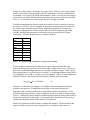
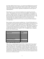
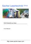
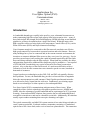
Applications for
Free-Space Optical (FSO)
Communications
Mark E. Allen
SignalWise LLC
[email protected]
Introduction
As bandwidth demands grew rapidly in the past five years, substantial investment was
made constructing high fiber-count, high capacity links between major cities – many of
these links include Wavelength Division Multiplexing (WDM) allowing several hundred
gigabits/sec of data to be transferred on a single fiber strand. Within the major cities,
high-count fiber cables are being deployed to interconnect Central Offices (COs), carrier
Points Of Presence (POPs) and major commercial buildings.
Users fortunate enough to be connected to this fiber network can obtain cost effective
high-speed connectivity between their corporate locations and to the Internet. However,
many buildings have yet to be connected and, in the current economic environment, the
incentives to construct additional fiber are not as they were just a few years ago. Service
providers can no longer justify making the capital investment required for the fiber links
that would bring customers onto the fiber network. When funds are available, the delays
and permitting required for additional fiber builds may also be prohibitive. Costs upward
of $250,000 with 6-month delays are typical of last-mile fiber lateral construction
projects. Also, at the edges of the fiber network, it’s much more difficult to achieve
economies of scale because construction costs cannot be spread over tens, hundreds or
thousands of customers.
Copper based access technologies such as DSL, DS1 and DS3 only partially alleviate
these problems. For one, the bandwidth they provide is at least an order of magnitude
below the amount enterprises could consume if their Gigabit speed internal networks
were allowed to freely expand into the wide-area. Furthermore, provisioning copper
based access technologies is often expensive, slow and unpredictable.
Free Space Optical (FSO) communications mitigates many of these issues. When
compared to other wireless technologies like point-to-point microwave, MMDS and
LMDS, it has the advantage of greater bandwidth and no requirements for FCC spectrum
licensing. Some unlicensed RF solutions show promise but are still bandwidth limited,
susceptible to interference, and can be vulnerable to rain fade. Additionally, RF solutions
usually require outdoor mounting that can require obtaining roof-rights.
The typical commercially available FSO system consists of two units facing each other to
create a point-to-point link. Each unit contains a transmitter consisting of a modulated
optical source like a laser diode, and a receiver based on a photodetector. The transmitter
1
includes electronics to process the digital signal (T1, DS3, OC3, etc.) and then uses this
bit stream to re-modulate a laser source. At the receiver, the photodetector collects the
light, focuses it on the photodetector and then processes these bits to recover the
underlying digital signal. FSO is essentially a fiber optic link without the fiber.
This paper provides an overview of some of the design issues associated with FSO and
some of the applications for this technology. The paper is organized in the following
manner. Section 2 describes some of the issues associated with FSO links. Section 3
discusses applications for FSO systems. Section 4 summarizes and concludes the paper.
FSO Design Issues
Because it uses optical signals transmitted through the atmosphere, free space optics is a
line-of-sight based technology. It doesn’t require FCC licensing for spectrum and so the
bandwidth is limited only by the modulation rates on the optical channels. However,
line of sight requires that the path between the transmitter and receiver be clear of
obstacles like trees, buildings, cranes, etc. Like microwave radio transmission systems,
roof mounting has been a common mounting location for FSO systems. Roof-mounted
FSO transmitters and receivers need to be environmentally hardened to deal with ice,
high winds, and dust. Roof mounting is usually accompanied by riser-runs to interconnect
the externally mounted system with the network equipment in the users wiring closet or
POP.
Indoor, “through window,” links are an attractive option for FSO. Wavelengths used by
typical FSO systems pass through glass windows but are affected by tinting and
imperfections in the glass. Although imperceptible to the eye, ripples and movement of
office building windows tend to be more challenging than tinting for FSO systems.
Subtle variations and vibrations in the glass cause the optical beams to be deflected away
from the intended receiver. An active system to correct for these imperfections and
movement in the glass is necessary to achieve an acceptable link budget while operating
through windows.
The optical signal is attenuated as is travels through the atmosphere. The primary cause
of this loss is Mie scattering resulting when fog particles, comparable in size to the
wavelength of light being transmitted (1.55um for example), cause the transmitted laser
light to be scattered randomly through the atmosphere rather than reach the receiver.
(See [Weich90].) As these water particles get larger and become rain, they no longer
affect FSO performance, but become similar in size to the wavelengths of microwave
communication systems and cause “rain-fade” at microwave frequencies. Exact
attenuation characteristics of various types of fog are a function of the water particle sizes
within the fog and can change as the fog evolves, or ages. Various techniques have been
used to measure these distributions exactly in order to form exact scattering models.
[Gerb91]
There has been some question recently as to how laser propagation varies through
different types of fogs that have different particle sizes. For example, coastal and marine
fogs tend to have smaller particle sizes implying that laser penetration should improve by
2
using lasers with a longer wavelength, say around 10um. However, heavy fogs include
particles with widely varying diameters and the attenuation is relatively independent of
wavelength. (See [Feig92] or [Mod] documentation.) In this case, the best way improve
performance is to ensure that the maximum possible optical power reaches the intended
receiver – in effect the reserve link margin should be as high as possible.
Visibility measurements at airports around the world have been recorded over the past
several years [NCDC]. The wavelengths at which these measurements are made are in
the visible range, normally around 550nm. Although propagation at 550nm is not
identical to propagation of 1550nm used for FSO, this data is ubiquitous and widely
available and these measurements are often the basis for predicting the FSO path
attenuation. For a detailed discussion, see [Kim], [Kim98].
Visibility
dB loss / km
5 km
1.2
2 km
4
1 km
9.3
500 m
21
400 m
27
300 m
38
200 m
60
100 m
128
Table 1. Loss per km (in dB) at 1550nm for varying levels of visibility.
In clear weather, transmission loss through free-space will be less than 1dB / km.
However, during heavy fog, loss can be on the order of 40dB / km or more. This loss is
part of the overall link budget and varies as visibility conditions change. Table 1 shows
losses through the air at various levels of visibility. A rough approximation using Table 1
for atmospheric loss, in dB, at 1550nm is given in Equation 1 where L is the length of the
link and Visibility is the measured meteorological visibility in the same units.
lossdB(L) ≅ 10 * L/Visibility
(1)
The index of refraction of air changes very slightly based on temperature, humidity,
turbulence and pressure. Scintillation occurs when a beam passes through the
atmosphere and encounters pockets of air with different indices of refraction. As the
beam transitions these pockets, it may be slightly diverted away from its intended target
receiver. Additionally, phase changes at different points across the image plane result in
destructive interference in the image. Correcting for these phase delays is necessary to
eliminate the dropouts caused by the destructive interference.
Some FSO systems use multiple beams to address this problem. The drawback to this
approach is that it requires the optical signals to be recombined at the receiver or
3
necessitates multiple electrical receivers. In a system where multiple beams are sent, the
hope is that the beams will travel through columns of air that are different enough from
each other that together the dropouts don’t cause the signal to be lost. In this case, each
optical signal must be received by a photodetector and then these electrical signals are
combined [Zhu02].
Mispointing losses occur when the transmitted beam is not optimally pointed at the
receiver. The transmitter, the receiver, or both can be misaligned. Laser transmission
systems are highly directional so small errors can substantially impact performance – in
particular over long-range links. One approach to this problem is to spread the area that
the beam illuminates so that small perturbations continue to illuminate the receiver. The
drawback to this is that a larger beam means wasted power because much of the
transmitted light never reaches the intended receiver. Active tracking systems to
constantly adjust the beam direction are necessary when narrow beams are transmitted
over long distances.
Beam divergence results in geometric spreading losses. For short FSO links this loss is
not significant, but for longer links divergence must be managed or substantial losses will
be incurred. For example, a beam with divergence of 3 mrads projects a spot size of 3
meters at 1 km distance. Assuming the receive aperture is approximately 0.25 meters, the
extra power projected outside the receive aperture is lost. The geometric spreading loss
is proportional to the illuminated area relative to the receive aperture size. In this case,
geometric spreading losses are 10 x log(0.252/3.02), or 21.6dB that can be a substantial
portion of the overall link margin.
Description
Transmit power
Internal losses (total for both ends)
Window losses
Path attenuation (clear air)
Scintillation loss
Mispointing loss
Geometric spreading loss
Required receiver sensitivity
Available weather margin
FSO
+20dBm
8dB
6dB
0dB
4dB
1dB
4dB
-30dBm
27dB
Table 2. Sample link budget for FSO system
Table 2 shows a sample link budget for an FSO link. Notice the bottom line giving the
“Weather margin.” From Table 1, note that as long as visibility stays just above 400
meters, the atmospheric loss along the link will be less than 27dB. Visibility at below
400m will impair the link. The probability of visibility dropping below a particular value
must be analyzed for each city where FSO installation is desired. Normally, this data is
integrated into an FSO link design tool that considers link distance, window quality, and
regional climate. Depending on link distance and city, link availability may be anywhere
from 99.99% for shorter links in fog-free cities to 95% or less on very long links (several
km) where low visibility is common.
4
FSO Applications
Several applications are enabled by FSO. As we know, the popularity of fiber is due
mainly to its huge bandwidth capacity and that the signals are contained within the
medium thereby eliminating electromagnetic interference and related security concerns.
FSO shares these attributes as it can supply virtually high bandwidth with no interference
potential. This is with very low probability of detection or interception due to its small
beam diameter. Below are some of the applications enabled by FSO:
Metro Fiber Extension
Metropolitan fiber networks are built within cities to connect major carrier hotels, central
offices, and serving wire centers. These networks are configured in rings with radiuses of
several miles. Central Business Districts (CBD)s will have additional fiber installed
forming a grid connecting additional large commercial locations. Although most
buildings do not have main fiber routes passing directly through them, they are typically
within a mile or two of fiber.
However, to push fiber the additional mile or less can be very costly. Unlike high-traffic
metro ring routes, there is not sufficient justification to install high fiber count cables to
individual customers. Consequently, the cost to install fiber to a single building is
dominated by the installation cost of the fiber rather than the cost of the fiber itself.
Most service providers use OC-12 or OC-48 multiplexers to offer SONET OC-N, Gigabit
Ethernet, DS3, and DS1 services. FSO allows them to use the same ADM equipment for
services in non-fibered buildings. This simplifies management, sparing and training and
thus reduces costs. Service providers can continue to use the same alarm handling and
performance management systems with which operations personnel are familiar.
For protection and restoration, operators use SONET 1+1, UPSR or BLSR. FSO can
passively pass all SONET overhead bytes. This allows FSO and fiber to be used
interchangeably to support the working and protect path on the SONET links.
Optical Ring Completion
Ring architectures are used to provide maximum reliability in fiber networks. Service
providers usually deliver services in the metro area from a SONET based network that
incorporates Unidirectional Path Switch Rings (UPSR) or Bi-directional Line Switched
Rings (BLSR). In fact, ring architecture is required to achieve 5 9’s uptime since singlethreaded fibers alone in a metro are severed too often to provide this level of uptime. As
the equipment is installed, fiber must be obtained and/or built in order to provide the fiber
over which to install the equipment. This situation is not unique to SONET. Other
technologies such as metro Ethernet networks, ATM, and Resilient Packet Rings (RPR)
also rely on diverse fiber routes to ensure maximum uptime. FSO provides a substitute
for fiber when it’s not available to complete the ring.
5
Enterprise Bandwidth Augmentation
It’s common for enterprises to occupy several buildings that are within a relatively small
geographic area, or campus. In some cases the buildings may be adjacent to each other or
a few blocks apart. When the enterprise manages the buildings and the space between
them, they may have installed or can easily install fiber as the enterprise is developed.
However, in most cases, the collection of buildings has developed as the company has
grown and they likely do not control a fiber network between the buildings. They likely
rely on a public service provider for copper and/or fiber based services to interconnect the
facilities.
The enterprise likely has one or more DS1s (1.544Mbps) to interconnect the voice PBXs
at the locations. In some cases they will also use data specific interconnections from
service providers. The local service provider likely provides Frame Relay or ATM PVCs
and possibly Metro Ethernet. These services have a high monthly recurring charge (often
more than $1,000 per month.)
This is an attractive application for FSO because the enterprise can make a one-time
expenditure and fulfill the requirements for high bandwidth data services between the
enterprise locations. The lower cost narrowband voice connections can be left with the
service provider to provide redundancy, but the high cost Frame, ATM, and Ethernet
leased transport can be replaced with FSO.
For mission-critical data services, the network can be engineered to provide 5 9’s
reliability. Critical data applications can be tagged using layer 2 / layer 3 priority
schemes such as ATM QoS, 802.1p, or diffserv. This will enable packets from the
mission-critical data applications to receive bandwidth over the narrow-band copper
connections in the event of an FSO link failure. In effect, layer 2/3 switches provide a
means for protection switching between two data channels with asymmetric bandwidths.
Video Backhaul and Distribution
Traditionally, satellite uplinks are used to transport high-quality video feeds from
sporting events, news locations, and other live events that need to be broadcast over the
major networks. The feeds normally go to main studios in locations like Los Angeles and
New York. The feeds are edited, filled with commercials and then broadcast through the
networks and their affiliates.
In some cases, fiber has been installed to these venues so that the video backhaul
connections are made when necessary. However, when fiber is unavailable, the
provisioning time may be too long to accommodate short timelines with new and special
events. Furthermore, it’s often impossible to determine what courthouse or remote
location will attract the next media event.
FSO enables broadcast quality video transmission without fiber. Broadcast quality digital
video is transmitted in formats like MPEG-2, which at normal levels is on the order of
20Mbps – squarely in the sweet spot of FSO.
6
Cellular, wireless, and 3G
In current first generation cellular networks, RF signals from the handsets are received by
a tower at a base stations and transferred onto the terrestrial network. The active calls are
processed and aggregated in a switch within the base station so that the amount a
bandwidth required on the terrestrial network is minimized. These backhaul connections
are nominally DS1 electrical signals that can be carried over copper, microwave, or fiber
when it’s available.
Direct RF Backhaul
The first generation cellular architecture described above involves a basestation function
at each cell antenna and minimizes the amount of bandwidth required on the terrestrial
network. However, the drawback of this architecture is that it requires many distributed
electrical switching systems, each needing to be sized to it’s peak demand, deployed
throughout the network. On average, the utilization of this distributed switching is low
and inefficient.
Emerging 3G systems support high-speed data within the wireless service offering. 3G
wireless protocols like EDGE and WCDMA support speeds of hundreds of kilobits / sec
at the handset. Consequently, the bandwidth generated at these antenna sites is much
greater than first generation cellular systems. This increase combined with the
requirement in any cellular network of reusing the spectrum results in a push towards
implementing a larger number of smaller cells in the 3G networks. This allows the
expensive and limited RF spectrum to be reused more often across a given geographic
area.
An architecture that includes very simplified antenna sites while centralizing the radio
and switching functionality is advantageous for future wireless networks dealing with
higher speed information from data-centric handsets and portable computers. Service
providers that evolve to this architecture leverage the low cost of bandwidth on fiberoptic cable. It also facilitates denser cells with higher bandwidth. Finally, it dramatically
simplifies finding tower locations because the tower equipment is greatly simplified. A
requirement of this architecture is to directly collect RF signals and transmit them on
fiber while eliminating the step of down-converting, de-multiplexing and switching the
individual wireless calls. High-speed samplers and modulators are required because the
RF processing is normally done on signals with bandwidths of 25MHz or more.
At the present time, there are two approaches to direct RF transport over fiber (or FSO) –
analog and digital. Unless the RF signals is first converted to digital, modulation of
optical transmitters with the direct RF signals requires maintaining a very high Signal to
Noise Ratio (SNR) of 50dB or more within the mixing and modulation process. If the
resulting optical signal needs to be amplified or is susceptible to noise being introduced,
it may be advantageous to convert the RF signals to digital.
The RF can be converted to an On-Off Keyed (OOK) bit streams where a more relaxed
SNR ~ 20dB is sufficient to achieve a low Bit Error Rate (BER) in the digital stream.
(See [Keis91].) As expected, converting the RF signals to a more robust digital bit
7
stream comes at the expense of increased bandwidth requirements in the modulated
optical signal. For example, consider a 25MHz RF signal. If this signal is sampled at
75Msamples/sec (1.5 times the Nyquist requirement) then each sample is quantized using
a 12 bit A/D to preserving approximately 70dB SNR in the analog signal [Oppen89].
The resulting bitstream is more than 1Gbit / s and occupies at least 2 GHz of bandwidth
on optical fiber. However, using WDM, many such bitstreams can be placed on a fiber
or a TFSO link allowing many RF signals to be simultaneously transferred on a link. In
fact, typical WDM configurations commonly transport multiple OC-48 (2.4Gbbps) or
Gigabit Ethernet (1.2 Gbps) signals, so components for this application are readily
available
Conclusion
Free Space Optical Communications has been discussed. The major factors that impact
the link budget of an FSO system were described. These include atmospheric loss,
geometric spreading loss, scintillation and losses do to mispointing.
Several applications for FSO system have been described. The applications best suited
for FSO are when high bandwidth is required, but fiber is unavailable. Through the use
of integration with wireline and fiber, the reliability of FSO can be improved to meet the
requirements of carriers and enterprise network operators.
References
[Feig92] R. P. Feigel, “XSCALE 92 User Manual – Natural Aerosol Extinction Module,”
Published with EOSAEL Software, see www.ontar.com.
[Gerb91] H. Gerber, Direct measurement of suspended particulate volume concentration
and far-infrared extinction coefficient with a laser-diffraction instrument, Applied Optics,
Vol 30, No. 33, November 20, 1991.
[Keis91] Gerd Keiser, Optical Fiber Communications, McGraw Hill, 1991.
[Kim] Issac I. Kim et. al, Comparison of laser beam propagation at 785 nm and 1550 nm
in fog and haze for optical wireless links, Optical Access Incorporated Website.
[Kim98] Issac I Kim et. al, “Wireless Optical Transmission of Fast Ethernet, FDDI,
ATM, and ESCON protocol data using the TerraLink Laser Communications System,”
Optical Engineering vol. 37 no. 12, December 1998.
[MOD] MODTRAN website.
[NCDC] United States National Climatic Data Center, http://lwf.ncdc.noaa.gov
[Stall02] W. Stallings, Wireless Communications and Networks, Prentice Hall, 2002.
[Stern99] Stern and Bala, Multiwavelength Optical Networks, Addison Wesley 1999.
8
[Szaj99] P. F. Szajowski, et al, “High Power Optical Amplifiers Enable 1550nm
Terrestrial Free-Space Optical Data-Link Operating @ 10Gb/s,” Proceedings of IEEE
Milcom 1999.
[Weich90] Hugo Weichel, Laser Beam Propagation in the Atmosphere, SPIE Press
1990.
[Oppen89] Oppenheim and Schafer, Discrete Time Signal Processing, Prentice-Hall
1989.
[Zhu02] Xiaoming Zhu and Joseph Kahn, “Free-Space Optical Communication Through
Atmospheric Turbulence Channels,” IEEE Transactions on Communications, August
2002.
9