1
Supplied by Drives Direct(Inverters) Ltd - 01623 720730
www.drivesdirect.co.uk
IMO
iDrive
EDX
AC micro-inverters for small
3-phase induction motors
100V series, 1-ph / 0.2 – 0.75kW (0.25 – 1HP)
200V series, 1-ph / 0.2 – 2.2kW (0.25 – 3HP)
200V series, 3-ph / 0.2 – 2.2kW (0.25 – 3HP)
400V series, 3-ph / 0.75 – 2.2kW (1 – 3HP)
Version V5.0807
Quick Start Guide
Quick Start Guide
Always read the full instruction manual before using iDrive.
This quick start guide is to assist in installing and running the iDrive to verify that the iDrive
and motor are working properly. Starting, stopping and speed control will be from the
keypad. If your application requires external control or special system programming, consult
the iDrive EDX instruction manual supplied with your inverter.
Step 1 - Before applying power to your iDrive
Please refer to Chapter One (Preface) and Chapter Two (Safety Precautions) of the iDrive
EDX instruction manual. Verify drive is installed in accordance with the procedures as
described in Chapter Three (Environment and installation). If something is suspected of being
abnormal, do not apply power to the drive until qualified personnel have corrected the
situation. (Failure to do so could result in death or serious injury.)
• Check inverter and motor nameplates to determine that they have the same power and
voltage ratings. Ensure that full load motor current does not exceed that of the inverter.
• With power OFF, remove the terminal covers to expose the motor and power terminals.
a. Verify that AC power is wired to L1(L), L2, and L3(N) .
b. Verify that motor leads are connected to T1, T2, and T3 .
c. If a brake module is necessary, please connect terminal voltage of the braking unit to P
and N of the inverter. Never connect a resistor directly to iDrive terminals P and N.
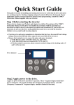
POWER ON
LED
7-SEGMENT
LED
DISPLAY
FREQUENCY
SETTING
POTENTIOMETER
iDrive EDX keypad
Step 2 - Apply power to your iDrive
Apply AC power to the drive and observe the keypad display. The 7-segment LED display
should show power voltage (ie 220) for 3~5 seconds and then show the Frequency Command
(Hz), factory set at 5.00. (Frequency Command shown on 7-segment display should be
flashing, ie inverter output OFF.)
i
Step 3 - Check low speed motor rotation direction without
load from keypad.
(See keypad diagram on previous page)
Press RUN/STOP key. 7-segment display will indicates 00.0 to 05.0. This number is the
frequency output value. The display will now become solid (not blinking) because the
inverter output is ON.
Check the operating direction of the motor.
IF the direction of the motor is incorrect:
Press RUN/STOP key, turn off the AC power supply. When the power indicator LED is
off, change over motor connections T1 and T2 for example.
Apply the power again, and then check the motor direction by pressing RUN/STOP key.
If rotation is correct press RUN/STOP key again.
Step 4 - Check full speed at 50Hz / 60Hz
Increase the frequency with , keys, press DATA/ENT to save this frequency.
Set frequency to 50Hz / 60Hz according to the above.
Press RUN/STOP key; check that the motor accelerates smoothly to full speed.
Press RUN/STOP key; check that the motor decelerates smoothly to zero speed.
Step 5 - Other settings
For other functions, please refer to iDrive EDX user manual.
Example:
Frequency Upper Limit (Hz)…………………………... P. 4-9
Frequency Lower Limit (Hz)…………………………….P. 4-9
Acceleration time (s)…..………………………………… P. 4-10
Deceleration time (s)…..………………………………… P. 4-10
Control mode (Vector, V/F)……...………………………P. 4-10
Motor rated current (A)….………………………………P. 4-13
Step 6 - Vector Mode Settings
If iDrive is required to run in Vector Mode (A06 = 001), the motor parameters need to be set.
The required data should found on the motor rating plate. (Motor kW = 0.75 ¯ HP)
The parameters to set for vector operation are:
Motor Rated Current (Amps) (b09)
See page 4-13
Motor Rated Voltage (Volts) (b10)
See page 4-13
Motor Rated Frequency (Hz) (b11)
See page 4-13
Motor Rated Power (KW) (b12)
See page 4-13
Motor Rated Speed (RPM) (b13)
See page 4-13
Additional Vector Mode Settings to adjust for optimum performance are:
Torque boost gain (b14)
See page 4-13
Slip compensation gain (b15)
See page 4-14
Low Frequency Voltage Compensation (b16) See page 4-14
ii
iDrive EDX user manual
Contents
Quick Start Guide ………………………………………….………… i
Chapter 0 ~ Preface ……………………………………………….… 0-1
0.1 Preface ………………………………………………………………. 0-1
0.2 Product inspection …………………………………………………... 0-1
Chapter 1 ~ Safety precautions……………………………………… 1-1
1.1 Operating precautions………………………………………………..
1.1.1 Before power up………………………………………………...
1.1.2 During power up………………………………………………..
1.1.3 Before operation ……………………………………………...
1.1.4 Leakage current! ………… …………………………………..
1.1.5 During operation………………………………………………
1.1.6 Operating environment ……………………………………….
1-1
1-1
1-2
1-2
1-2
1-3
1-3
Chapter 2 ~ Part number description..…………………………….
2-1
Chapter 3 ~ Environment description and installation………..…
3-1
3.1 Environment …………………………………………………………. 3-1
3.2 Environment precautions……………………………………………. 3-6
3.3 Electrical Installation………………………..………………………. 3-7
3.3.1 Notes for wiring…………………………………….………… 3-7
3.3.2 MC, MCCB, fuse and cable specifications …………………. 3-9
3.3.3 Ancillary power equipment – supply side…………………… 3-10
3.3.4 Safety and EMC: Good wiring practice ..………………...… 3-11
3.3.5 Long motor cables: effects of volt drop and capacitance….. 3-13
3.3.6 Input side AC reactor………………………………………… 3-13
3.4 Specification ………………………………………………………….. 3-14
3.4.1 Product individual specification..……………………………. 3-15
3.4.2 General specifications………………………………………… 3-16
3.5 Connection diagram………………………………………………….. 3-18
3.6 Description of iDrive power and control terminals………………… 3-19
3.7 iDrive dimensions ………………….…………………..……………. 3-22
3.8 Multi-iDrive installation with regenerative loads….……………….. 3-25
iii
Chapter 4 ~ Programming instructions & Parameter list……….
4-1
4.1 Keypad description…………………………………………………… 4-1
4.1.1 Keypad layout…………….…………………………………… 4-1
4.1.2 Local and Remote operating modes………………………… 4-1
4.1.3 Keypad navigation…………………………………………… 4-2
4.2 Parameter function list……………………………………………….. 4-3
4.3 Parameter function description………………………………………. 4-9
Chapter 5 ~ Trouble shooting and maintenance……………………
5.1 Fault indication and remedy…………………………………….…..
5.1.1 Fault/Error display and Diagnostics…………………………
5.1.2 Set up & Interface Errors ………………………..………….
5.1.3 Keypad operation error descriptions………………………..
5.2 General functional troubleshooting……….………………………....
5.3 iDrive Troubleshooting flowcharts ……………….…………………
5.4 Routine and periodic checks………….……………………………...
5.5 Maintenance and inspection………………………………………….
Chapter 6 ~ Options………………………………….…………………...
6.1
Option cards……………………………..……………………….…
6.1.1 RS-485 option card…………………..………………………
6.1.2 RS-232 option card……………………………………..……
6.1.3 Program copy option card…………………………………..
6.1.4 Remote keypad ……………………………………………..
6.1.5 2 IN/1OUT expansion card …………………………………
5-1
5-1
5-1
5-4
5-5
5-6
5-7
5-13
5-14
6-1
6-1
6-1
6-2
6-3
6-4
6-5
Appendix 1 iDrive EDX inverter parameter setting list……………… Appendix 1
iv
Chapter 0 Preface
Chapter 0 ~ Preface
0.1 Preface
To extend the performance of the product and ensure your safety, read this manual thoroughly before
using the iDrive. Should there be any problem in using the product that can not be solved with the
information provided in the manual, contact your nearest IMO distributor or the company from who
you purchased the product from.
Precautions
The iDrive is an electrical / electronic product. For your safety, there are symbols such as “Danger”
and “Caution” in this manual to remind you to pay attention to safety instructions on carrying,
installing, operating, and checking the iDrive. Be sure to follow the instructions carefully for safety.
Danger
Indicates a potential hazard that may cause death or serious personal
injury to operator or other persons if misused
Caution
Indicates that the iDrive or a mechanical system might be damaged if
misused
Danger
Do not touch any circuit boards or internal parts until the charge indicator is extinguished
after turning the power off.
Do not connect any wires when the inverter is powered. Do not check parts and signals on
circuit boards when the inverter is in operation.
Do not disassemble the iDrive and modify internal wires, circuits and parts.
Connect the PE (protective earth) terminals of the iDrive correctly. Always follow the
advice given in this manual and conform to local / national regulations in force.
Caution
Do not perform a high voltage insulation test on parts inside the inverter. High voltages can
easily destroy the iDrive’s semiconductor components.
Do not connect T1 (U), T2 (V), and T3 (W) terminals of the inverter to AC power source.
CMOS ICs on the iDrive’s main board are sensitive to static electricity.
Do not touch the main PC board even when power is off, or damage may occur.
0.2 Product Inspection
iDrive EDX inverters have all passed a full function test before delivery. Please check the
following when you receive and unpack the inverter:
The model and capacity of the inverter is the same as those specified on your order.
Is there any damage caused during transportation? If so, do not apply power.
Contact IMO distributor or authorised sales representative if any of the above are found to be
incorrect..
0-1
Chapter 1 Safety Precautions
Chapter 1 ~ Safety Precautions
1.1 Operating Precautions
1.1.1 Before Power Up
Caution
The line voltage applied must comply with the iDrive’s specified input voltage.
Danger
Make sure the main circuit connections are correct. L1(L), L2, and L3(N) are power-input
terminals and must not be confused with T1, T2 and T3. Otherwise, the iDrive might be
damaged.
Caution
To avoid dropping the iDrive do not hold by the front cover when carrying. Carry by
supporting the main body moulding only as damage could occur if dropped.
To avoid fire, do not install the iDrive on a flammable surface or in an enclosure manufactured
from combustable material. If possible always install on metal surface.
If several iDrives are placed in the same control panel, add extra heat dissipators to keep the
temperature below 50oC to avoid overheating or fire.
When removing or installing the remote keypad, turn the power off first, and operate the
keypad following the instructions in this manual to avoid error.
NOTE
When connected as detailed in this manual, this product complies with IEC 61800-3, with
built-in EMC filter for Unrestricted Distribution. Conformance should be tested before use
in some environments.
1-1
Chapter 1 Safety Precautions
1.1.2 During Power up
Danger
The iDrive still has control power if the time of power loss is very short. When the power
is re-applied, the inverter operation is controlled by parameter b31.
The iDrive operation is controlled by parameters A00, b31, b32 and b33 and the status of
any FWD/REV RUN switch. Please be sure to consider the following settings: 1. When A00=000, the inverter will not auto restart when power is re-applied.
2. When A00=001 and operation switches FWD/REV RUN are OFF, the inverter will not
auto restart when power is re-applied.
3. When A00=001 and operation switch ON and b33=000, the inverter will auto restart
when power is re-applied. Please turn OFF the run (start) switch to avoid potential
damage to machine and injury to operator before the power is re-applied.
When b33=000 (direct start on power up), please refer to the description of b33 to verify
the safety of operator and machine.
1.1.3 Before operation
Caution
Make sure the model and capacity are the same as that set in parameter b89
1.1.4 Earth / ground leakage current
WARNING
Warning! iDrive models with built-in EMC filter can give leakage current > 3.5mA.
ALWAYS ENSURE INVERTER IS CORRECTLY EARTHED / GROUNDED.
Follow instructions given in Section 3 of this manual in ALL installations.
•
DO NOT use iDrive EDX inverters on ungrounded (floating) power supplies.
•
iDrive should be used in fixed installations only.
Operating iDrive EDX with Residual Current Device (RCD):
1.
Leakage current may cause nuisance trip when RCD setting is <200mA
2. Only one inverter should be supplied from each RCD.
1-2
Chapter 1 Safety Precautions
1.1.5 During operation
Danger
Do not connect or disconnect the motor while iDrive is operating otherwise the inverter
and/or the disconnecting device may be damaged by the high level of switch-off current.
Danger
To avoid electric shock, do not remove the front cover when power is on.
After a power-loss (under-volt) trip occurs, the motor will restart automatically when power is restored
if auto-restart function is set. In this case, care must be taken while working with the machine.
Note: External Emergency stop must mechanically open and un-latch the power supply to the
iDrive without any chance of re-closing until required. It is not permitted to rely upon software
control for an emergency stop.
Caution
Do not touch heat-generating components such as heat sink and brake resistor.
The inverter can operate the motor from low speeds to very high speeds.
Verify the allowable speed ranges of the motor and the load before operation.
Note the settings related to the braking unit.
Do not check signals on circuit PCB while the inverter is running.
Caution
Allow a minimum of 5 minutes for iDrive to discharge after power down before attempting
to disassemble or checking the components within the drive.
1.1.6 Operating environment
Caution
iDrive can be used in a non-condensing atmosphere in temperature range from -10oC to
+50 oC and relative humidity of 95%, but the environment should be free from corrosive or
explosive gasses, condensation or conductive dust.
1-3
Chapter 2 Model description
Chapter 2 ~ Part numbering description
iDrive product rating label (example)
Do not inspect components unless the lamp is off
See manual for correct installation and operation
! CAUTION
Model: EDX-040-21-E
INPUT: AC 1 phase 50 / 60Hz
OUTPUT:AC 3 phases 0 – 200Hz
Motor Rating: 0.5HP / 0.4KW
VOLTAGE: 200 – 240V (+10%, -15%)
VOLTAGE:
0 - VIN
IRMS : 5.4A
IRMS : 3.1A
IMO Precision Controls Ltd
IP20 / UL Open Type (rated -10°C to 50°C Ambient)
WARNING: THIS PRODUCT MUST BE EARTHED IN ACCORDANCE WITH THE
iDRIVE V4 (OR LATER) INSTRUCTION MANUAL AND LOCAL/NATIONAL WIRING
CODES IN FORCE WHERE THIS iDRIVE IS TO BE INSTALLED.
iDrive part numbers – key to product rating label
EDX
Series:
-
040
Nominal
motor capacity:
020:
0.18kW / 0.25 HP
040:
0.37kW / 0.5 HP
075:
0.75kW / 1.0 HP
150:
1.5kW / 2.0 HP
220:
2.2kW / 3.0 HP
-
2
1
Input
voltage:
E
-
Input
phases
EMC filter :
Enclosure
1:100V
1: 1- phase
E: Integrated Filter
2:230V
3: 3-phase
Blank: No Filter
4: 400V
-
N4S: IP65
/NEMA4 + water
and dust-proof
isolator / switch /
potentiometer
N4: IP65
No switches etc
Blank: IP20
2-1
Chapter 3 Environment description and installation
Chapter 3 Environment description and installation
3.1 Environment
The environment will directly effect the operation and the life of the iDrive.
Always install the iDrive in an environment that complies with the following conditions:
• Ambient temperature: -10°C ~ +50°C
•
Avoid exposure to rain or moisture.
•
Avoid direct sunlight.
•
Avoid smoke and salinity.
•
Avoid erosive liquid and gas.
•
Avoid dust and conductive particles.
•
Keep away from radiation and
flammable materials.
•
Avoid sources of strong electromagnetic interference
•
Avoid vibration. Use vibration-proof mounts if the situation can not be avoided.
•
•
If several inverters are placed in the same control panel, additional cooling must be
used to keep the temperature below 50oC.
FAN
FAN
iDrive
iDrive
iDrive
iDrive
iDrive
iDrive
Front view - OK
Front view - X
Side view - OK
120mm
iDrive
iDrive
120mm
50mm
50mm
Enclosure front view
50mm
Enclosure side view
3-1
Side view - OK
Chapter 3 Environment description and installation
•
The chassis of this model has DIN rail clip device to use when rail mounting.
Removal from DIN-RAIL
Installing onto DIN-RAIL
•
All iDrive IP20 models can be installed side-by-side when temperature is below
50°C.
3-2
Chapter 3 Environment description and installation
199 mm (7.83”)
• iDrive EDX- 040-21 / 075-21; 040-11 / 075-11-N4S (IP65) type installation:
100~120V
OR
200~240VAC
50/60Hz
123.4 mm (4.86”)
(PE)
NOTES A :
1. Isolating switch, REV-0-FWD switch and potentiometer are only
for EDX-######- N4S models
2. Power supply cable : 600V AC rated PVC
3. Motor cable : 600V AC rated PVC / (screened or armoured)/PVC
4. Maximum torque on terminal screws :
(1). Power/motor cable (plug in) terminal : 5kg-cm(4.34 in-lb)
(2). Remote control wire : 4kg-cm (3.47 in-lb)
(3). Outer cover (M4) : 6kg-cm (5.20 in-lb)
(PE)
Fuses /
fuse/link or
MCB type
circuit
protection
AC
100~120V
or
200~240V
50/60HZ
L1
L2
(PE)
Isolator
T1
3
PHASE
M
T2
T3
(PE)
REV-0-FWD
Switch
S2
24V
S1
TM2
Potentiometer
10V
AIN
COM
3-3
NOTES B:
(1). Input power : single-phase (L1,L2, (PE))
ensuring supply is 100~120 or 200~240VAC
according to model type.
(2). Motor output: three-phase (T1,T2,T3, (PE) ).
Caution: Do not start or stop the motor
by switching input power
‧For EV-######-N4S type :
Ensure that the REV-0-FWD switch is set at ‘0’
position so that the iDrive has no run signal
at power-on otherwise injury may
result.
Chapter 3 Environment description and installation
• EDX-###-##-N4S installation :
Caution!
When removing front cover as shown
be careful not to pull or stress any
pre-wired internal power or control
connecting cables.
TM2
TM1
TM2
TM1
3-4
Chapter 3 Environment description and installation
• EDX-###-##-N4 installation :
Caution!
When removing front cover as shown
be careful not to pull or stress any
pre-wired internal power or control
connecting cables.
TM2
TM1
TM2
TM1
3-5
Chapter 3 Environment description and installation
3.2 Environmental precautions
Do not use the inverter in an environment with the following conditions:
Direct sunlight
Salt
Corrosive gas and liquid
Wind, rain, and water
drops may get into
Oil
Iron filings, dust
Excessive vibration
Extreme low temperature
Excessive high
temperature
Electromagnetic wave
and ultra high wave
Radioactive materials
Inflammable materials
3-6
Chapter 3 Environment description and installation
3.3 Electrical Installation
3.3.1 Notes for wiring
A. Screwdriver torque:
Connect cables and tighten to the torques listed below.
Horsepower
KW
0.25/0.5/1 0.2/0.4/0.75
0.25/0.5/1 0.2/0.4/0.75
2/3
1.5/2.2
1/2/3
0.75/1.5/2.2
Tightening torque
Power source
Nominal tightening torque for TM1 terminals
100-120V
0.74/0.1
8.66/10
(lbs-ft / Kg-m)
(lbs-in / Kg-cm)
200-240V
1.286/0.18
15.97/18
200-240V
(lbs-f t / Kg-m)
(lbs-in / Kg-cm)
380-480V
B. Power cables (connected to TM1):
Power cables are connected to L1(L), L2, L3 (N), T1, T2, T3, P and N. Choose cable in
accordance with the following criteria:
(1) Use cable with copper cores only. Select cable with insulation diameter based on working
conditions at 221oF / 105oC.
(2) For nominal voltage ratings, use cable rated at minimum 300V for 240Vac iDrive and
600V rated cable for 480Vac iDrive.
C. Control cables (connected to TM2):
Control cables are connected to TM2 control terminals. Choose cable in accordance with the
following criteria:
(1) Use cable with copper cores only. Select cable with insulation diameter based on working
conditions at 221oF / 105oC.
(2) For nominal voltage ratings, use cable rated at minimum 300V for 240Vac iDrive and
600V rated cable for 480Vac iDrive.
(3) To avoid noise interference, do not run control cables in the same conduit or trunking as
power cables. Where possible use screened / shielded control cables to minimise
electromagnetic interference. To avoid ground loops always earth the shield at one end
only.
D. Nominal electrical specifications of terminal block TM1:
KW
0.2 / 0.4 / 0.75
0.2 / 0.4 / 0.75
1.5 / 2.2
0.75 / 1.5 / 2.2
HP
0.25 / 0.5 / 1
0.25 / 0.5 / 1
2/3
1/2/3
Power source
100-120V
200-240V
200-240V
380-480V
3-7
Volts
Amps
600
15
600
40
Chapter 3 Environment description and installation
E. Fuse types
Drive input fuses are necessary to disconnect the drive from the power supply in the event of component failure in
the drive’s power input circuit. The iDrive’s electronic protection circuitry is designed to clear output short circuits
and ground faults without blowing the input fuses. The table below shows the iDrive EDX input fuse ratings.
To protect the iDrive most effectively, use fuses with quick-blow characteristics (semi-conductor fuses).
It is the responsibility of the user/installer to ensure that the correct fuse protection (or other) is applied.
RK5, CC/T type fuses for iDrive EDX
110V input models (1-phase)
EDX-
HP
KW
020-11
040-11
075-11
0.25
0.5
1
0.2
0.4
0.75
100% CONT
Max.RK5
Max.CC or T
Output AMPS (A) FUSE Rating(A) FUSE Rating(A)
1.7
0.53
10
20
3.1
0.88
15
30
4.2
1.6
20
40
EDX-
HP
KW
KVA
020-21
040-21
075-21
0.25
0.5
1
0.2
0.4
0.75
150-21
2
1.5
220-21
3
2.2
100% CONT
Max.RK5
Max.CC or T
Output AMPS (A) FUSE Rating(A) FUSE Rating(A)
1.7
0.53
8
15
3.1
0.88
10
20
4.2
1.6
15
30
7.5
2.9
20
40
10.5
4.0
25
50
EDX-
HP
KW
KVA
020-23
040-23
075-23
0.25
0.5
1
0.2
0.4
0.75
150-23
2
1.5
220-23
3
2.2
100% CONT
Max.RK5
Max.CC or T
Output AMPS (A) FUSE Rating(A) FUSE Rating(A)
1.7
0.53
5
8
3.1
0.88
8
10
4.2
1.6
12
15
7.5
2.9
15
20
10.5
4.0
20
30
EDX--
HP
KW
KVA
075-43
150-43
220-43
1
2
3
0.75
1.5
2.2
1.7
2.9
4.0
KVA
220V input models (1-phase)
220V input models (3-phase)
440V input models (3-phase)
100% CONT
Max.RK5
Max.CC or T
Output AMPS (A) FUSE Rating(A) FUSE Rating(A)
2.3
6
10
3.8
10
15
5.2
10
20
UL class fuses overload characteristics.
RK5 - type has a time delay characteristic
T-type is quick-blow
CC – type have both types of characteristic
*Fuse ratings are based upon 250V fuses for 120V inverters, and 300V fuses for 240V inverters, and 600V
for 480V inverters.
3-8
Chapter 3 Environment description and installation
3.3.2 MC, MCCB, Fuse and cable specifications.
MCCB/ MC/ Fuse
z IMO warranty will not apply under the following condition.
(1) MCCB or fuse is not installed or incorrectly installed or installed with over
capacity, which has resulted in iDrive failure.
(2) MC or capacitor or surge absorber is connected in series between inverter
and motor.
iDrive EDX model
Fuse
MCCB
MC
(from IMO)
Power
Input/Output
cables (c.s.a.)
Earth/ground
cables PE
terminal (c.s.a.)
Control
terminals (TM2)
###-11/21/43
020-11/040-11
040-11
040-21-E
10A
300Vac
10A
MC14-S
075-21-E
075-23
###-43(-E)
150-21-E
220-21-E
16A
300Vac
150-23
220-23
075/150/220
20A
300Vac
16A/600Vac
20A
32A
MC18-S
MC32-S
2
2.5mm / (13 AWG)
16A
2
4 mm / (11AWG)
Terminal screw M4
Terminal screw M4
See Note
1
Below
4 mm 2 / (11AWG)
Terminal screw M4
MC18-S
2.5mm 2 / (13
AWG)
Terminal screw
M4
4 mm 2 (14AWG)
Terminal screw M4
Cable dimension 0.75mm 2 (18AWG) Terminal screw M3
Notes
1. To comply with BS7671 requirements the iDrive must be earthed by a conductor(s) of
minimum 4 mm2 c.s.a. with additional mechanical protection. Therefore the iDrive must be
installed in a steel enclosure and wired according to the diagram on page 3-11.
2. Use a single fuse in the live line for 1-phase input iDrive models where supply is L+N.
Where L+L supply is to be used, each line must be fused.
For 3-phase input models, each L1(L)/L2/L3(N) phase must be fused or protected by MCCB.
3. A suitable three-phase ‘squirrel cage’ induction motor must be used with iDrive.
4. If an iDrive is to operate more than one motor in parallel, the total operating current should
be less than or equal to the iDrive’s rated output current.
A suitable thermistor should be installed in each motor to protect from winding over-heat.
5. Do not install a capacitor, LC, or RC network between the iDrive and the motor.
3-9
Chapter 3 Environment description and installation
3.3.3 Ancillary power equipment – supply side:
Power supply
Power supply:
• Make sure the voltage applied is correct to avoid
damaging the iDrive.
MCCB / Fuse
Moulded-case circuit breaker MCCB:
• Use a MCCB that matches the rated voltage and current of
the iDrive to control the power ON/OFF and protect the
input wiring.
• Do not use the MCCB as the switch for running and
stopping the motor.
MC
ACR
ELCB / RCD
iDrive
Fuse:
• A suitable rated fuse(s) should be installed between the
iDrive and the AC power source to protect the wiring if a
MCCB has not been used.
Earth Leakage circuit breaker ELCB / RCD:
• To prevent error operation caused by filter leakage current
install a RCD with a trip current range of 30mA or
greater, and action time <0.04 seconds. In case of models
EDX-150-21-E and EDX-220-21-E a RCD with trip
current range >200mA should be used.
Magnetic contactor MC:
• If required use a suitably rated magnetic contactor
between the power supply and the iDrive input terminals.
• Do not use the magnetic contactor as the run/stop switch
for the iDrive.
AC Reactor for power improvement ACR:
• When iDrives are supplied with high capacity (above
600KVA) power source, an AC reactor can be installed
between the iDrive and the AC power souce to improve
Power Factor, reduce harmonic currents and increase
short-circuit protection – see page 3-12. An ACR can also
be used on the motor side when cable is very long.
EMC filter:
• Standard iDrive’s have an integrated EMC filter to reduce
electromagnetic interference to other equipment connected
to the same AC power supply.
iDrive:
• Output terminals T1, T2, and T3 are connected to U, V,
and W terminals of the motor.
• To avoid damaging the iDrive, do not connect the motor
terminals T1, T2, and T3 to AC power.
3-10
Chapter 3 Environment description and installation
3.3.4 Safety and EMC: Good wiring practice IP20 models
L1
L2
415V 50Hz
3-phase + N
Power supply
* 10mm
L3
N
E/Ground
2
4mm2
BACK PLATE
(paint/coating free)
L1(L)
L3(N)
PE
iDrive
EDX-220-21-E
(for example)
P N T1 T2
Optional ferrite
choke, only required
if motor cable is
very long.
Note: For very long
cables an ACR
should be used
T3
PE
4mm2
ENCLOSURE
Brass earth studs
fixed through
back plate and
secured with
shake-proof
washers.
NB. Both ‘PE’
terminals must be
linked to back
plate with
4mm2 (min) cable
as shown.
**
* NOTE 1
External earth /
ground conductor
if used.
Enclosure (& backplate) must
be connected to main earth system
by single 10mm2 c.s.a. copper
conductor to conform to BS7671
Earth / ground
cables connected
through isolator
Local
Isolator
** NOTE 2
Armoured or
screened cable,
3C or 4C.
Screen
connected at all
ends as shown.
Motor
Note: Power supply side ancillary equipment
not shown in this diagram, for clarity.
3-11
**
Screen / armour must
be connected as shown
at each end of cable
sections.
If motor connection
box is plastic, screen
must be secured to the
metal frame of the
motor.
Chapter 3 Environment description and installation
Further good EMC practice IP20 models
•
Connect the power cable including Earth as shown
Use shielded (screened) or steel wire armoured cable'
Strip the cable cover and clamp the screen
to backplate
L1 L3 PE1
panel
L1 (L2) L3 PE
panel
Frame 1
Frame 2
U V W PE
UVW
Frame 2
Frame 1
**PE1 &PE2 don't connect inside the inverter
Panel grounding
Panel grounding
Motor
Motor
Clamp screen to the motor frame
Connector length should be short <50mm.
Clamp screen to the motor frame
Connector length should be short < 50mm.
•
•
•
•
A ferrite choke in the output of the main circuit can suppress conducted emissions. To limit
the effects of radiated emissions unscreened motor cables should be put in an earthed metal
conduit. Do not run control cables inside conduit or within 30 cm of the motor cables.
If control/signal cables must cross over motor cables, ensure that they do so at right angles
(90°).
The supply and output (PE) terminals should to be connected to ground to increase noise
immunity of the integrated EMC filter.
To prevent RF interference resulting in iDrive operation error, control circuit wiring should
be shielded and twisted. Please refer to following diagram, connect shielded wire to ground
terminal at one end only. The wiring distance should be less than 50m.
Shield
PVC coating
Do not connect this end
To ground (PE) terminal
Wrapped with
insulating tape
•
•
•
Earth / ground wiring should be made as short and thick as possible. Copper braided tape is
better than cable for this application, but not always practical.
Do not ‘daisy-chain’ the earth / ground of the inverter to other equipment. Connect the (PE)
terminal to a centralized main earth / ground point and ‘star’ connect all other equipment
ground wires to this point.
Do not make a loop when several inverters share a common ground point.
3-12
Chapter 3 Environment description and installation
(a) Correct
(b) Incorrect
(c) Incorrect
To ensure maximum safety, use correct wire size for the main power circuit and control circuit
according to the required wiring regulations.
On completion, check that the wiring is correct and terminal screws are secured.
3.3.5 Long motor cables: effects of volt drop and capacitance
When the cable between the iDrive and the motor is too long, the effect of volt drop along the cable
and cable capacitance must be considered. For very long cables it is sometimes necessary to use
iDrive one frame size higher than motor power rating.
Phase-to-phase voltage drop (Vd )
Vd =
3 × resistance of wire (Ω/km) × length of line (mts) × current × 10-3
To prevent RF problems and excessive high frequency ground leakage currents the iDrive carrier
frequency (function b86) should be adjusted based on the length of the motor cable, for example:
Motor cable length
Carrier frequency (b86)
3.3.6
< 25m
< 50m
< 100m
> 100m
< 16kHz
< 12kHz
< 8kHz
< 5kHz
Input side AC reactor
An AC input reactor can be installed to reduce the harmonic content of the iDrive input current. If
the harmonic distortion is reduced, the RMS input current is also reduced.
An AC reactor can also be installed on the output side of iDrive when the motor cable is excessively
long and can counter the effect of cable capacitance and nuisance tripping. Contact IMO for details.
Input reactor specifications
iDrive model
EDX -
040-21-#
075-21-#
150-21-#
220-21-#
075-43-#
150-43-#
220-43-#
Line input side AC inductance (typical)
Current (A)
5.0
5.0
19.0
25.0
2.5
5.0
7.5
3-13
Inductance (mH)
2.1
2.1
1.1
0.71
8.4
4.2
3.6
Chapter 3 Environment description and installation
IP65 / NEMA4 - EMC good practice guide EDX-150-21, 220-21, 075-43, 150-43, 220-43
NOTES!
NOTES:
1) For EDX-150-21-E – N4S and EDX-220-21-E-N4S models, additional items will be found
inside the outer packaging including 2pc of EMC conformed waterproof (IP65) ferrite core.
2) If application requires meeting published EMC performance class, you must fit the ferrite
cores onto the motor cable outside the plastic sheath as shown in the above diagram. The
quadrilateral type ferrite core should be fitted as close as possible to inverter output terminals
T1, T2, T3, and the circular type ferrite core should be fitted close to the motor.
Please also note that the length of the motor cable CANNOT exceed 5 metres if the declared
EMC performance is to be met.
3-14
Chapter 3 Environment description and installation
3.4 Specification
3.4.1 Product individual specification
100V model
iDrive
EDX-□□□ -11
200V model
EDX-□□□ -21 (-E)
EDX-□□□ -23
Horsepower (HP)
020
0.25
040
0.5
075
1
020 040 075 150 220 020 040
0.25 0.5 1
2
3 0.25 0.5
075
1
150
2
220
3
Suitable motor capacity (kW)
0.2
0.4
0.75
0.2
0.4 0.75 1.5
Rated output current (ARMS)
1.7
3.1
4.2
1.7
3.1 4.2
Rated capacity (kVA)
0.53
2.2
0.2
0.4
0.75 1.50
2.2
7.5 10.5
1.7
3.1
4.2
10.5
7.5
Output voltage range (V)
0.88 1.60 0.53 0.88 1.60 2.90 4.00 0.53 0.88 1.60 2.90 4.00
1-phase
1-phase
3-phase
200~240V+10%,
100~120V+10%,
200~240V+10%,
-15% (50/60Hz)
-15% (50/60Hz)
-15% (50/60Hz)
3-phase 0~240V
Input current (ARMS)
7.1
12.2
17.9
Net weight (Kg)
Allowable momentary power
loss time (S)
Enclosure
0.62
0.68
0.72 0.71 0.73 0.73 1.25 1.3
0.61 0.61 0.66 0.95
1.0
1.0
1.0
1.0
Input voltage range (V)
4.3
1.0
1.0 1.0
2.0
21
2.0
3.0
4.0
1.0
6.4
1.0
IP20
400V model
EDX-□□□ -43 (-E)
iDrive
Horsepower (HP)
Suitable motor capacity (kW)
Rated output current (ARMS)
Rated capacity (kVA)
Input voltage range (V)
Output voltage range (V)
Input current (ARMS)
Net weight (Kg)
Allowable momentary power
loss time (S)
Enclosure
5.4 10.4 15.5
075
1
0.75
2.3
1.7
3.0
1.68
1.0
150
2
1.50
3.8
2.9
3-phase 380~480V+10%, -15% (50/60Hz)
3-phase 0~480V
4.8
1.70
2.0
IP20
Standard Models
Non-Standard Models
3-15
220
3
2.2
5.2
4.0
6.6
1.73
2.0
9.4
2.0
12.2
1
2.0
Chapter 3 Environment description and installation
General control
Frequency control
3.4.2 General Specifications
Output Frequency range 0~200Hz
Starting torque
100% / 3Hz (Vector mode)
Speed Control Range 20:1 (Vector mode)
Speed Control
±0.5% (Vector mode)
accuracy
Setting resolution ※1 Digital: 0.1Hz(0~99.9Hz)/1Hz(100~200Hz); analog: 0.06Hz/ 60Hz
Keypad setting
Set directly with▲▼ keys or the potentiometer VR on the keypad
Display / Indication
7 segment*3. Displays frequency / DC voltage / output voltage /
output current / inverter parameters / alarm log /software version /
PID feedback control
External signal setting •External variable resistor / 0-10V/ 4-20mA
•Performs up/down control (Motorized Pot.) with multi-function
programmable inputs on the terminal base.
Frequency limit
Possible to set Upper and Lower frequency limits, and two-stage
functions
skip-frequencies.
Carrier frequency
4~16KHz (default 10KHz, above 10KHz with de-rating)
V/F pattern
Select 6 fixed patterns 50Hz/60Hz or 1 user programmable pattern
Acc/dec control
Two independent sets of accel / decel ramps (0.1~999s)
Multi-func. analog O/P 6 functions (refer to b53 description)
Multi-func. digital I/P’s 19 functions (refer to b35~b38 description)
Multi-funct. relay O/P 16 functions (refer to b55 description)
1* Relay output as standard SPST.---- selectable as multi-function
DO (relay output)
output. 1* optional external multi-function output (open-collector
transistor 24V, 600mA)
Selectable NPN/PNP: 4 inputs (S1~S4) as standard;2 extra inputs
DI (digital inputs)
(S5~S6) available on option card.
Set speed command and PID feedback signal
AI (analog input)
(speed, PID, 4~20mA / 0~10V)
Instantaneous power loss restart, Speed search, auto-restart, DC
Other functions
brake, torque boost, 2 / 3wire control and PID control.
•RS485 Option card:Modbus RTU/ASCII modes,
Communication control 4800~38400 bps, max. 254 stations
•PC/PDA software
Operation temperature -10~50°C (inside enclosure) IP20 ; -10~40 IP65
Storage temperature
-20~60°C
Humidity
0 – 95% RH (non condensing)
Vibration immunity
1G (9.8m/s2)
Internal EMC filter: First Environment, Restricted Distribution.
EMC ※2
External EMC filter: First Environment, Unrestricted Distribution.
In accordance with EN61800-3
LVD
Conforming to EN50178
Enclosure
IP20
Safety Class
UL508C
3-16
Protective Functions
Chapter 3 Environment description and installation
Over load protection Inverter rated current 150%/1min
International
UL/cUL/CE
conformity
Over-voltage trip
200V Class: DC voltage >400V. 400V Class: DC voltage >800V
Under-voltage trip 200V Class: DC voltage <190V. 400 Class: DC voltage <380V
Instantaneous
Set to enable or disable
power-loss restart
Stall prevention
ACC/DEC/ Operation stall prevention and stall prevention level.
Output terminal
Electronic circuit protection
short circuit
Other faults
Electronic circuit protection
Over-current, over-voltage, under-voltage, overload, instantaneous power-loss
Other function
restart, ACC/DEC / RUN stall prevention, output terminal short circuit,
grounding error, reverse block, direct start at power on and fault reset limit.
※1:
The setting resolution above 100Hz is 1Hz when set by keypad, and 0.01Hz when set using
serial communication from computer (PC) or programmable controller (PLC).
※2:
Non-standard, un-filtered iDrive model numbers EDX-020-21 to EDX-075-21, and EDX-07543 to EDX-220-43 fitted with optional external filter are in accordance with EN61800-3 First
Environment; Unrestricted Distribution when carrier frequency is set at 10KHz or less.
Non-standard, un-filtered iDrive model numbers EDX-150-21 and EDX-220-21, fitted with
optional external filter are in accordance with EN61800-3 First Environment; Unrestricted
Distribution when carrier frequency is set at 10KHz or less.
Standard, filtered iDrive model numbers EDX-020-21-E to EDX-075-21-E, are in accordance
with EN61800-3 First Environment; Restricted Distribution when carrier frequency is set at
10KHz or less.
Model numbers EDX-150-21-E and EDX-220-21-E are in accordance with EN61800-3 First
Environment; Restricted Distribution when carrier frequency is set at 6KHz or less.
IP65 / NEMA4 iDrive models EDX-020-21-E-N4(S) to EDX-220-21-E-N4(S) and EDX-07543-E-N4(S) to EDX-220-43-E-N4(S) are in accordance with EN61800-3 First Environment;
Restricted Distribution when carrier frequency is set at 10KHz or less.
3-17
Chapter 3 Environment description and installation
3.5 iDrive EDX connection diagram
Optional brake module for
braking high-inertia loads.
Requires suitable resistor.
Power terminals
• Single phase 100~120V
• 1/3 phase 200~240V
• 3 phase 380~480V
PNP common terminal
Multi-function
digital input
‘x’
terminals
12/24Vdc
Braking
Module
Optional braking
resistor
L1(L)
T1
L2
T2
L3(N)
T3
PE
PE
(3) 24V
RA (1)
(4) S1
RB (2)
Motor
Multi-function digital output relay
(5) S2
(6) S3
SW1: Digital signal selector NPN / PNP
(UP = NPN / DOWN = PNP)
SW2: Control signal selector switch
(UP = 0~10Vdc / DOWN = 4~20mA)
NPN common terminal
(8) COM
Multi-function analog
input terminal
• Set Frequency
• PID feed back input
(9) 10V
10kΩ
FM
SW2
SW1
(7) S4
(10) AIN
(11) COM
S5
S6
(12) FM+
T+
T24V/0.6A
• Optional interface
• Multi-function input
output card
(2 IN/ 1 OUT)
• Remote keypad
Note 1:- Connect point ‘x’ to either: Terminal (3) (internal +24Vdc) for PNP mode (positive switching)
(3) 24V
(4)S1, (5)S2, (6)S3, (7)S4
OR…
Terminal (8) (Common 0V) for NPN mode (negative switching).
(8)COM
(4)S1, (5)S2, (6)S3, (7)S4
Note2:- External 24Vdc may be used to supply the external contacts at point ‘x’.
If so then connect the 0V of the external supply to Common (terminal 8).
3-18
Chapter 3 Environment description and installation
3.6
Descriptions of iDrive Power and Control terminals
Power input, power output, and earth/ground terminal block descriptions
Terminal
L1(L)
L2
Description
Main power input Single-phase: L1/L3(N)
Three-phase: L1/L2/L3
L3(N)
⊕
⊖
T1
T2
T3
PE
DC link and braking module* connection terminals.
Never connect resistors directly to these terminals or damage will occur!
Inverter output.
Connect appropriate 3-phase AC induction motor to these terminals.
Earth / Ground terminals (2 points)
*A brake module is required for applications where a load with high inertia needs to be stopped
rapidly.
Use a correctly rated braking module and resistor(s) to dissipate the energy generated by the load
during stopping or rapid speed change for example otherwise iDrive may trip on over-voltage ‘OV’.
3-19
Chapter 3 Environment description and installation
Control signal terminal block description
4
5 6
7 8 9 10 11 12
S1
S2
S4
1 2 3
TM2
FM+
AIN
COM
Description
Multi-functional output terminals.
Normally open relay contacts SPST
RB
10V
AIN
RA
10V
COM
S3
24V
RB
RA
Terminal
Rated contact capacity:
(250VAC/10A resistive)
(Refer to parameter b55 for functions)
+10Vdc terminal. Supply for external potentiometer for speed reference.
Analog frequency command input or PID feedback signal terminal.
(Refer to parameter b41)
24Vdc common terminal; Frame size 1 maximum current = 100mA
24V
Frame size 2 maximum current = 150mA
PNP (SOURCE) for inputs S1~S4 (and option card inputs S5 and S6).
Set SW1 to ‘PNP’ position. Connect option card power supply if required.
0Vdc common terminal.
COM
NPN (SINK) for input, S1~S4 (and option card inputs S5 and S6).
Set SW1 to ‘NPN’ position. Connect option card power if required.
Also use this terminal for analogue input and analogue output signals - common.
Multi-function analog output terminal, (refer to parameter b53 for functions)
FM+
Output signal: 0-10Vdc proportional to b53 setting.
Maximum output current = 25mA
Terminal
S1
S2
S3
Description
Multi-function input terminals (refer to parameters b35~b38 descriptions)
Maximum input current per terminal: Frame size 1 = 20mA.
Frame size 2 = 25mA
S4
3-20
Chapter 3 Environment description and installation
SW1 and SW2 function description
SW1
External signal logic
Remarks
NPN input (SINK)
Factory setting = PNP
PNP input (SOURCE)
External input
(for speed/frequency reference)
SW2
Remarks
V
0~10Vdc analogue signal
I
Effective when
Function A01= 002
(external analogue
input to terminal AIN)
V
I
4~20mA analogue signal
3-21
Factory setting = V
Chapter 3 Environment description and installation
3.7 iDrive Dimensions
IP20 Frame 1: 1-phase 100V: EDX-020-11 ~ EDX-075-11
1-phase 200V: EDX-020-21 ~ EDX-075-21, EDX-020-21-E ~ EDX-075-21-E
3-phase 200V: EDX-020-23 ~ EDX-075-23
Frame 1
A
132 / 5.2
B
123.5 / 4.86
C
67 / 2.64
D
77 / 3.03
3-22
E
F
130.5 / 5.13 128.45 / 5.06
G
8 / 0.315
Chapter 3 Environment description and installation
IP20 Frame 2: 1-phase 200V: EDX-150-21 ~ EDX-220-21; EDX-020-21-E ~ EDX-075-21-E
3-phase 200V: EDX-150-23 ~ EDX-220-23
3-phase 400V: EDX-075-43 ~ EDX-220-43; EDX-075-43-E ~ EDX-220-43-E
Frame 2
A
132 / 5.2
B
123.5 / 4.86
C
D
108 / 4.25 118 / 4.65
3-23
E
148 / 5.83
F
144 / 5.67
G
8 / 0.315
Chapter 3 Environment description and installation
IP65 Frame 1: 1-phase 100V models: EDX-020-11-N4S ~ EDX-075-11-N4S
1-phase 200V models: EDX-020-21-E-N4S ~ EDX-075-21-E-N4S
IP65 Frame 2: 1-phase 200V models: EDX-150-21-E-N4S & EDX-220-21-N4S
3-phase 400V models: EDX-075-43-E-NS4 ~ EDX-220-43-E-N4S
3-24
Chapter 3 Environment description and installation
3.8 Multi-iDrive installation with regenerative loads
Built in
braking
resistor
DC link parallel
connections
+→+→+→+
-→-→-→If all iDrives are of the same voltage rating, the DC bus connections of each can be
connected together in parallel. Regenerated braking power from stopping of high inertia
loads can then be dissipated or partly dissipated between all of the paralleled iDrives.
If more energy requires dissipating, a braking module and resistors can be connected as
shown above.
Note: All drives must power on at the same time*.
Notes:
•
*If parallel connecting the DC busses of different capacity inverters;
Must power up in sequence: Largest capacity first → smallest capacity last.
•
DC fuses and/or other precautions may be necessary.
•
Never connect ‘+’ terminals to ‘–‘ terminals or damage will occur.
If in doubt consult your local iDrive distributor or dealer.
3-25
Chapter 4 Software index
Chapter 4 Programming instructions & Parameter list
4.1 Keypad
4.1.1 Keypad layout
4.1.2 Local and Remote operating modes
Local mode
Run Command
Set (A00 = 000): Run command only from RUN / STOP keys on the keypad.
Frequency command
Set (A01 = 000): UP/DOWN keys on keypad control the motor frequency (speed).
Set (A01 = 001): only the ‘Freq.Set’ potentiometer (VR) on the keypad can control the motor speed.
Remote mode
Run Command
Set (A00 = 001): Run command only by digital input to TM2 terminal S1 to S4.
Terminals S1 to S4 can be configured for ‘RUN’ input by setting functions (b34 to b38 = 000 / 001)
Frequency command
Set (A01 = 002): only external speed reference to TM2 terminal 10 (AIN) can control the motor speed.
Note: Switch SW2 and (b61 = 000 / 001) must be set for either 0-10V or 4-20mA input.
Tip!
Quick changeover between LOCAL and REMOTE control modes can be made by
simultaneously pressing the
RESET
and the
DATA
ENT
keys on the keypad.
Modes can be ‘toggled’ by this method when commissioning for example.
Note that the motor must be stopped before changeover is allowed.
4-1
Chapter 4 Software index
4.1.3 Keypad navigation
Start
PARAMETER
DISPLAY
STATUS
DISPLAY
(When b93 = 001)
Power ON
UOP
A##
Flashing display
shows frequency
at stop
*4
RESET
*1
*3
DATA
ENT
*2
DATA
ENT
dCU
VALUE
DC voltage
DSP
FUN
DSP
FUN
00.0~60.0
DSP
DSP FUN
FUN
DSP
FUN
A##
RUN
STOP
VALUE
AC voltage
DSP
FUN
05.0
․
DATA
ENT
DATA
ENT
EXISTING
DATA
AOP
VALUE
AC current
Solid display shows
running frequency
DSP
FUN
ENTER
NEW
DATA
DATA
ENT
PId
RESET
VALUE
PID Feedback
NEW
DATA
STORE
NEW
DATA
DSP
FUN
DATA
ENT
End
after 0.5s
*1: Display flashes with set frequency in STOP mode.
*2: Display is steady (not flashing) with set frequency in RUN mode.
(Required output frequency can be set during both STOP and RUN modes.)
*3: If parameter A12 = 000 (factory setting) then display returns to RUN/STOP frequency.
If parameter A12 = 001, b parameters will now be visible.
*4: If parameter b93 = 001, STATUS DISPLAYS will now be opened.
4-2
Chapter 4 Software index
4.2 Parameter functions
Quick-Start ‘A’ parameter function list
Parameter
Number
Function
A00
Operation control
A01
Frequency control
A02
A03
A04
A05
Frequency high limit
Frequency low limit
Acceleration time 1
Deceleration time 1
A06
Control mode select
A07
A08
A09
A10
V/F Pattern set
Output voltage at base frequency
Base frequency
Torque Boost Gain [V/F]
Electronic thermal overload relay
protection for motor (OL1)
A11
A12
Range / (Units)
Factory
Setting Notes
000: Keypad RUN/STOP keys
001: Terminals
000
002: RS232/485 Comms
000: Keypad UP/DOWN keys
001: Potentiometer on Keypad
002: AIN signal (TM2)
000
003: MFIT : Mot. Pot. function
004: RS232/485 Comms
01.0 ~ 200 (Hz)
50.0/60.0 *2
00.0 ~ 200 (Hz)
00.0
*2
00.1 ~ 999 (s)
05.0 *1, *2
00.1 ~ 999 (s)
05.0 *1, *2
000: Vector control
001
*4
001: V/F control
001 ~ 007
001
198 ~ 264, 380 ~ 528 (V)
220 / 440
00.2 ~ 200 (Hz)
50.0/60.0
00.0 ~ 30.0 (%)
00.0
*1
000: Enable motor protection
000
001: Disable motor protection
000: b-parameters CLOSED
000
001: b-parameters OPEN
Access to ‘b##’ parameters
Advanced ‘b’ parameter function list (Access to these parameters by setting A12 = 001)
Parameter
Number
Function
b00
b01
b02
b03
b04
b05
b06
b07
b08
b09
b10
b11
b12
b13
Acceleration time 2
Deceleration time 2
Slip Compensation Gain [V/F]
Motor No-Load Current [V/F]
Output Voltage at Max Frequency [V/F]
Mid Output Frequency [V/F]
Output Voltage at Mid Frequency [V/F]
Min Output Frequency [V/F]
Output Voltage at Min Frequency [V/F]
Motor Rated Current
Motor Rated Voltage
Motor Rated (Base) Frequency
Motor Rated Power
Motor Rated Speed
Range / (Units)
4-3
00.1 ~ 999 (s)
00.1 ~ 999 (s)
00.0 ~ 100 (%)
--- (A)
00.0 ~ 100 (%)
00.1 ~ 200 (Hz)
00.0 ~ 100 (%)
00.1 ~ 200 (Hz)
00.0 ~ 100 (%)
--- (A)
--- (V)
--- (Hz)
--- (KW)
--- (RPM/10)
Factory
Setting Notes
05.0
05.0
00.0
--100
25.0
50.0
00.5
01.0
-----------
*1, *2
*1, *2
*1
*4
*4
*4
*4
*4
*4
Chapter 4 Software index
b14
b15
b17
b18
b19
b20
b21
b22
b23
b24
b25
b26
Torque Boost Gain
Slip Compensation Gain
Low Frequency Dead-Band Voltage
Compensation
DC Injection Braking Time
DC Injection Braking Start Frequency
DC Injection Braking Level
Skip Frequency 1
Skip Frequency 2
Skip Frequency Bandwidth
Acceleration Stall Prevention Level
Deceleration Stall Prevention Level
Running Stall Prevention Level
Stall Prevention Deceleration Time
b27
Acceleration Stall Prevention
b28
Deceleration Stall Prevention
b29
Running Stall Prevention
b30
Stall Prevention Time During Running
b31
Power Loss Auto Re-start
b32
Auto Re-start Attempts
b33
Auto-Start at Power ON
b34
Reset Mode
b35
Terminal S1 Function
b36
Terminal S2 Function
b37
Terminal S3 Function
b38
Terminal S4 Function
b39
Terminal S5 Function
b16
001 ~ 450 (%)
001 ~ 450 (%)
000 ~ 040
00.0 ~ 25.5 (s)
01.0 ~ 10.0 (Hz)
000 ~ 020 (%)
00.0 ~ 200 (Hz)
00.0 ~ 200 (Hz)
00.0 ~ 30.0 (+/-Hz)
050 ~ 200 (%)
050 ~ 200 (%)
050 ~ 200 (%)
00.1 ~ 999 (s)
000: Enabled
001: Disabled
000: Enabled
001: Disabled
000: Enabled
001: Disabled
000: According to (A05)
001: According to (b26)
000: Enabled
001: Disabled
000 ~ 005
000: Auto-Start Enabled
001: Auto-Start Disabled
000: Reset command available
if RUN command is OFF
001: Reset command available
if RUN is ON or OFF
000: RUN Forward
001: RUN Reverse
002: Preset Speed Command 1
003: Preset Speed Command 2
004: Preset Speed Command 3
005: JOG Frequency Command
006: Emergency STOP (E.S.)
007: Base Block (b.b.)
008: Select Accel 2 / Decel 2
009: Reset
010: UP Command
011: DOWN Command
012: Control Signal Switch
013: Communications Mode
014: Accel. / Decel. Prohibit
015: Master / Auxiliary Speed
Signal
4-4
00.5
01.5
005
00.0
00.0
00.0
200
200
200
03.0
000
000
000
000
001
000
001
000
000
001
005
006
007
*1
*1
*1
Chapter 4 Software index
b40
Terminal S6 Function
b41
Terminal AIN Function
016: PID Disabled
017: Analog Frequency Signal
Input Terminal AIN
018: PID feedback signal (AIN)
019: DC Brake (ON command)
000: UP/DOWN Control ON
b42
Frequency UP/DOWN Control (MFIT)
b43
b44
b45
b46
b47
b48
b49
b50
b51
b52
S1 ~ S6 Digital Input Scan Time
Jog Frequency
Preset Frequency 1
Preset Frequency 2
Preset Frequency 3
Preset Frequency 4
Preset Frequency 5
Preset Frequency 6
Preset Frequency 7
Preset Frequency 8
b53
0-10V Analogue Output Select
b54
Analogue Output Gain
b55
Multi-Function Output Relay RY1
b56
b57
Output Frequency Reached Set Value
Frequency Detection Range
(Freq. Held at Power OFF)
001: UP/DOWN Control ON
(Freq. Reset to 0Hz at OFF)
002: UP/DOWN Control ON
(As 000 – UP/DOWN is
Available when Output OFF)
001 ~ 100 (mS x 8)
00.0 ~ 200 (Hz)
00.0 ~ 200 (Hz)
00.0 ~ 200 (Hz)
00.0 ~ 200 (Hz)
00.0 ~ 200 (Hz)
00.0 ~ 200 (Hz)
00.0 ~ 200 (Hz)
00.0 ~ 200 (Hz)
00.0 ~ 200 (Hz)
000: Output Frequency
001: Set Frequency
002: Output Voltage
003: DC Voltage
004: Output Current
005: PID feedback Signal
00.0 ~ 200 (%)
000: RUN
001: Frequency Reached
(± b57)
002: Frequency in Range
(b56 ± b57)
003: Frequency Detected
(>b56)
004: Frequency Detected
(<b56)
005: Fault
006: Auto Reset / Restart
007: Momentary Power Loss
008: Emergency Stop (E.S.)
009: Base Block (b.b.)
010: Motor Overload
011: Inverter Overload
012: xxx Not Used xxx
013: Power ON
014: Communication Error
015: Output Current (>b58)
00.0 ~ 200 (Hz)
00.0 ~ 30.0 (±Hz)
4-5
009
017
000
010
05.0
05.0
05.0
10.0
20.0
30.0
40.0
50.0
60.0
*1
*1
*1
*1
*1
*1
*1
*1
*1
000
*1
100
*1
000
00.0
00.0
*1
*1
b58
b59
Output Current Reached Set Value
Output Current Detection Time
b60
Multi-Function Output Transistor
(T+ / T- Option Card)
b61
AIN Signal Select
b62
b63
AIN Gain
AIN Bias
b64
AIN Bias
b65
AIN Slope Direction
b66
AIN Analogue Input Scan Time
b67
PID Operation Mode
b68
b69
b70
b71
Feedback Gain
P: Proportional Gain
I: Integral Time
D: Differential Time
b72
PID Bias/Offset
b73
b74
b75
b76
b77
PID Bias Adjust
PID Filter Time
PID Sleep Level
PID Sleep On-Delay Time
Serial Communications Address
Chapter 4 Software index
000
00.0
000 ~ 100 (%)
00.0 ~ 25.5 (S)
000: RUN
001: Frequency Reached
(± b57)
002: Frequency in Range
(b56 ± b57)
003: Frequency Detected
(>b56)
004: Frequency Detected
(<b56)
005: Fault
006: Auto Reset / Restart
007: Momentary Power Loss
008: Emergency Stop (E.S.)
009: Base Block (b.b.)
010: Motor Overload
011: Inverter Overload
012: xxx Not Used xxx
013: Power ON
014: Communication Error
015: Output Current (>b58)
000: 0-10V
001: 4-20mA
000 ~ 200 (%)
000 ~ 100 (%)
000: Positive
001: Negative
000: Positive
001: Negative
000 ~ 100 (mS x 4)
000: PID Control Disabled
001: PID Bias D Control
002: PID Feedback D Control
003: PID Bias D Reverse
Control
004: PID Feedback D Reverse
Control
0.00 ~ 10 (%)
0.00 ~ 10 (%)
00.0 ~ 10 (s)
0.00 ~ 10 (s)
000: Positive Direction
001: Negative Direction
000 ~ 109 (%)
00.0 ~ 02.5 (s)
00.0 ~ 200 (Hz)
00.0 ~ 25.5 (s)
001 ~ 254
4-6
005
000
100
000
*1
*1
000
*1
000
*1
050
000
1.00
01.0
10.0
0.00
*1
*1
*1
*1
000
*1
000
00.0
00.0
00.0
001
*1
*1
*3 *4
Chapter 4 Software index
b78
b79
b80
b81
b82
b83
b84
b85
b86
b87
b88
b89
b90
b91
b92
b93
b94
b95
b96
b97
000: 4800 (bps)
001: 9600
Serial Communications Baud Rate
002: 19200
003: 38400
000: 1 Bit
Stop Bits
001: 2 Bits
000: No Parity
Parity Bit
001: Even Parity
002: Odd Parity
000: 8 Bits
Data Bits
001: 7 Bits
Communication Error Detection Time
00.0 ~ 25.5 (s)
000: Decelerate to Stop (A05)
001: Coast to Stop
Communication Error Response
002: Decelerate to Stop (b01)
003: Continue to Run
000: UP/DOWN Keys
Remote Keypad Frequency Control (by)
001: Potentiometer (VR)
000: Remote keypad disabled
001: Remote keypad enabled
Remote Keypad – Enable / Disable
(Motor stopped as set by b92)
(and action if keypad cable fault)
002: Remote keypad enabled
(No stop, runs at Set Freq)
Carrier Frequency
004 ~ 016 (kHz)
000: Auto Run by Inverter °C
001: Run When Output On
Inverter Cooling Fan
002: Always Run
003: Always Stop
000: Forward
Motor Rotation Direction
001: Reverse
Inverter Power Code (Read Only)
See following description
000: FWD/STOP-REV/STOP
RUN / STOP / Direction Switching
001: RUN/STOP-FWD/REV
002: 3-Wire – RUN/STOP
000: Reverse Enabled
Reverse RUN Instruction
001: Reverse Disabled
000: Decelerate to STOP
STOP Method
001: Coast to STOP
000: Display Hz Only
Operation Monitor
001: Display Hz, A, V, PID, etc
000: Module Disabled
001: Copy iDrive to Module
Copy Module
002: Copy Module to iDrive
003: Read / Write Check
010: Reset to Default (50Hz)
All Data Reset to Factory Settings
020: Reset to Default (60Hz)
Software Version (Read Only)
CPU Version
Alarm Log
Last 3 fault records
4-7
003
*3 *4
000
*3 *4
000
*3 *4
000
*3 *4
00.0
*3
000
*3
000
000
010
001
IP20
Only.
000
*1
000
000
000
000
000
*3
000
*3 *4
*3 *4
Chapter 4 Software index
Note: *1: Parameter value can be modified when iDrive output is on (motor running).
*2: Frequency resolution is 1Hz for settings above 100 Hz.
*3: Cannot be modified during communication.
*4: Do not change while making factory setting.
b95 factory setting is 010 (50Hz) and motor parameter value is 140.
b95 factory setting is 020 (60Hz) and motor parameter value is 170.
4-8
Chapter 4 Software index
4.3 Parameter Function Description
Basic ‘A’ parameter functions
000: Keypad
001: External Terminal
002: Communication Control
1.) A00 = 000, iDrive RUN/STOP command is from keypad.
2.) A00 = 001, iDrive RUN/STOP command is from external terminals.
3.) A00 = 002, iDrive RUN/STOP command by serial communication.
A00 Operation Control
(Run / Stop Command)
000: UP/Down keys on keypad
A01 Frequency Control
(Speed Reference Source) 001: VR on keypad (Potentiometer)
002: Control terminal 10 input signal (TM2)
003: Multi-function input terminal UP/DOWN function
004: Frequency set by serial communication
(When b85 = 1: Remote keypad has priority)
1.) A01 = 001, when one of parameter group b35 ~ b38, or b41 is set to 015 and multi-function
input terminal is OFF, the frequency is set by VR on keypad. If the multi-function input
terminal is ON, the frequency is set by analog signal (auxiliary speed) from TM2.
2.) A01 = 002,when one of parameter group b35 ~ b38, or b41 is set to 015 and multi-function
input terminal is OFF, the frequency is set by analog signal (auxiliary speed) from TM2. If the
multi-function input terminal ON, the frequency is set by VR on keypad.
3.) Up/Down terminal: Refer to description of parameter group b35~ b38 (multi-function input
Terminal)
4.) Priority of reading frequency command: Jog > preset frequency > (Keypad▲▼ or TM2 UP/
Down or communication)
A02 Frequency upper limit (Hz) : 01.0 - 200
A03 Frequency lower limit (Hz): 00.0 - 200
Out put frequency
A02 (Frequency upper limit)
(Note)
A03 (Frequency lower limit)
Command Frequency
Note: If A02 = 0 Hz and frequency command = 0Hz, the iDrive will zero-speed stop.
If A03 > 0 Hz and frequency command = 0 Hz iDrive output will be at A03 set value.
4-9
Chapter 4 Software index
A04 Acceleration time 1 (s): 00.1 – 999
A05 Deceleration time 1 (s): 00.1 – 999
Formula for acceleration/deceleration time:
Denominator is based on factory setting in Sensorless Vector control
a) Motor rated frequency (Sensorless Vector control).
b) Max output frequency (V/F control).
a)
Set frequency
Acceleration time = A04 ×
b11 (rated frequency)
Set frequency
Deceleration time =A05 ×
vector
b11 (rated frequency)
b)
Set frequency
Set frequency
Acceleration time = A04 ×
Deceleration time = A05 ×
A09 (Max output frequency)
V/F
A09 (Max output frequency)
A06: Control mode
Vector control or V/F control
A06 = 000: iDrive operates in Sensorless Vector mode. Dynamic response to changing load is
improved, motor starting torque increased and low-speed operation is more stable. For better S/V
control it is also necessary to input correct values into parameters A08, A09, b09 – b16.
A06 = 001: iDrive operates in V/F mode. Standard performance for fans, pumps, and other nondemanding (non-dynamic) loads.
A07: V/F Preset patterns 1 – 7
A07 = 007.
Selects user configurable V/F pattern by setting parameters A09, b04 – b08.
Care should be taken when using this feature as incorrect setting of these parameters may cause
motor over-heating or incorrect operation.
b04
(Vmax)
b06
(Vmid)
b08
(Vmin)
b07
b05
A09
4-10
Chapter 4 Software index
4-11
Spec.
General
003
A07
004
High start torque
002
U.S.
CAN
005
Variable torque
General
001
V/F Pattern
60 Hz Motors
Spec.
A07
High start torque
50 Hz Motors
E.U.
Variable torque
A07 = 001 ~ 006 User selectable fixed V/F patterns (refer to following table).
006
V/F Pattern
Chapter 4 Software index
A08 V/F Base Voltage
A09 V/F Base Frequency
In example below: A09 = 50Hz, b04 =100%
If A08 setting is 200~240V, then output voltage for the pattern:
A08 = 240
A08 = 220
240
220
200
A08 = 200
50.0Hz (A09)
The iDrive output voltage cannot exceed its input voltage.
A10 V/F Torque Boost Gain 00.0 – 30.0%
A11 Electronic thermal overload protection
for motor (OL1) :
000: Protection Enabled
001: Protection Disabled
Set A11 = 000 and b09 to rated motor current (Amps) to give correct thermal overload protection.
A12 Advanced parameter
functions display
000: Disable access to advanced parameters (b parameters)
001: Enable access to advanced parameters (b parameters)
A12 = 000. Parameter group ‘b’ cannot be displayed or accessed.
A12 = 001. Enable display and access parameter group ‘b’.
4-12
Chapter 4 Software index
Advanced ‘b’ parameters functions
b00 Acceleration time 2 (s): 00.1 – 999
b01 Deceleration time 2 (s): 00.1 – 999
b02 V/F Slip Compensation Gain 00.0 – 100%
b03 Motor no-load current (A)
Motor no-load current differs with iDrive capacity b89. Adjust according to motor information.
b04: Output voltage ratio at max. frequency (%)
00.0 – 100%
b05: Mid frequency (Hz)
00.1 – 200Hz
b06: Output voltage ratio at mid. frequency (%)
00.0 – 100%
b07: Min. output frequency (Hz)
00.1 – 200Hz
b08: Output voltage ratio at min. frequency (%)
00.0 – 100%
b04~b08 please refer to A07 description
b09 Motor rated current (A)
b10 Motor rated voltage (V)
b11 Motor rated base frequency (Hz)
b12 Motor rated power (kW)
b13 Motor rated speed (RPM)
b14 Torque Boost Gain (Only for vector control, A06 = 001)
If motor load torque increases, this function increases the available output torque to match the load.
ΔTe =
I
(load current)
¯
Gain
(torque boost)
• Torque/Speed curve pattern:
Torque
C%
ΔTe : Increase output torque capacity
B%
A%
RPM
Q
• Operating frequency range: 0 ~ Motor rated frequency
4-13
Chapter 4 Software index
• When the motor output torque is not enough, increase b14 set value.
• If the motor vibrates or becomes very hot decrease b14 set value.
• If running at low speeds for long periods, high b14 set value can cause the motor to overheat
• The maximum output torque limit is proportional to the iDrive rated current.
• If increasing b14 set value causes the output current to be too large, increase b03 set value.
b15
Slip Compensation Gain (Only for vector control, A06 = 001)
If the detected motor load is too large, speed will drop. Increase gain b15 to compensate.
ΔFslip =
I
(load current)
¯
Gain
(slip compensation )
• Torque/Speed curve pattern:
ΔFslip
C%
B%
A%
RPM
Q
• Operating frequency range: 0 ~motor rated frequency.
• When the motor load is high, speed will decrease (slip). Increase b15 set value to compensate.
• If the motor vibrates or becomes very hot decrease b14 set value.
• The maximum rotational output speed limit is fixed by the motor maximum set frequency.
b16 Low Frequency DB Voltage Compensation (Only for Vector control, A06 = 001)
Increasing b16 set value will increase output voltage and low frequency torque.
• Output voltage/frequency pattern:
V
b16
F
• Operating frequency range: 0~10HZ / 50HZ
0~12HZ / 60HZ
• At low operating frequency: When the motor output torque is not enough increase b16 set value.
4-14
Chapter 4 Software index
b17 DC braking time (s) 00.0~25.5
b18 DC braking start frequency (Hz) 01.0~10.0
b19 DC braking level 00.0~20.0%
b17 / b18: DC braking time and start frequency, as following figure:
Hz
b18
t
b17
b20 Skip Frequency 1 (Hz) : 00.0 – 200
b21 Skip Frequency 2 (Hz) : 00.0 – 200
b22 Skip Frequency Hysterisis (± Hz) : 00.0 – 30.0
Example: When b20 = 10.0Hz
b21 =20.0Hz
b22 = 02.0Hz
10Hz
20Hz
±2Hz = Motor cannot run between 8-12Hz (10Hz ± 2Hz )
±2Hz = Motor cannot run between 18-22Hz (20Hz ± 2Hz)
b22
b21
b20
b23
b24
b25
b26
b27
Acceleration stall-prevention level: 050% ~ 200%
Deceleration stall-prevention level: 050% ~ 200%
Run stall-prevention level: 050% ~ 200%
Stall prevention deceleration time: 00.1 ~ 999s
Acceleration stall-prevention:
= 000: Enable Stall prevention during acceleration.
= 001: Disable Stall prevention during acceleration.
b28 Deceleration stall-prevention:
= 000: Enable Stall prevention during deceleration.
= 001: Disable Stall prevention during deceleration.
b29 Run stall-prevention:
= 000: Enable Stall prevention in Run mode.
= 001: Disable Stall prevention in Run mode.
b30 Stall prevention time during run mode.
= 000: according to A05 (Deceleration Time 1).
= 001: according to b26.
4-15
Chapter 4 Software index
1.) When the acceleration time is set too short the iDrive may trip on Over-Current (OC).
If the time accelerating time cannot be increased use stall-prevention. A stall-prevention level
needs to be programmed and when the inverter detects this level it freezes the acceleration
ramp until the current falls below the set level, then continues accelerating.
2.) When the Deceleration time is set too short the iDrive may trip on Over-Voltage (OU).
If the time deceleration time cannot be increased then stall-prevention can be used. A stallprevention level has to be programmed and when the inverter detects this level it holds the
deceleration ramp until the DC link voltage falls below the factory set level, then continues
decelerating.
3.) The iDrive could stall during run mode due to an impact load or sudden changes of the load.
Stall prevention in run mode will detect a programmed stall level (b25) for a period of time
(b30) , if the level exceeds b25 , then the iDrive reduces its output frequency (speed) to
provide the required additional torque to overcome the stall condition. Once this level is
below the programmed stall level then it ramps up to its normal running speed.
b31 Auto restart on momentary power loss. 000: Enabled
001: Disabled
b31 = 000: Auto restart after a momentary power loss is enabled on resumption of power and
application of run signal, according to setting of parameter A00.
The iDrive will carry out an auto speed search, once the motor speed and direction are found then it
will accelerate to the running speed prior to the power loss.
b31 = 001: Auto restart disabled.
b32 Auto restart times: 000 ~ 005
1.) b32 = 000: The iDrive will not auto-restart on fault trip.
2.) b32 > 000
The iDrive will carry out an auto-speed search 0.5 sec after the fault trip, while the output
is switched off and the motor is coasting to stop.
Once the rotating speed is determined the iDrive will accelerate or decelerate from this speed to the
running speed before the fault.
3.) Auto restart will not occur following OL1, OL2, OH, or BB alarms.
Note:- Auto restart will not function while DC injection braking or decelerating to stop.
b33 Auto-start on power up
000: Enable direct start on power up.
001: Disable direct start on power up.
Danger:
1.) When b33 = 000 and external run mode (A00 = 001) are selected and a RUN command is
present, the iDrive will auto-start the motor when power is applied.
This feature should only be considered when all safety implications of its use have been
investigate, risk assessment for maintenance, use of warning labels etc.
2.) When b33 = 001 and external run mode (A00 = 001) are selected, and a RUN command is
present, the motor will not auto-start when power is applied to the iDrive.
The iDrive display will flash and SP1’ error message. It can only restart after the RUN
command has been removed then reapplied.
4-16
Chapter 4 Software index
b34 Reset mode
000: Reset is enabled only when a RUN command is OFF.
001: Reset is enabled when a RUN command is OFF or ON.
b34 = 000. Fault cannot be reset therefore iDrive cannot start if a RUN command is ON (A00=001)
b35 ~ b38, b41
Selectable Functions for input terminals (S1 - S4 & AIN )
000: Run Forward
001: Run Reverse
002: Preset Speed Command 1
003: Preset Speed Command 2
004: Preset Speed Command 3
005: Jog frequency Command
006: Emergency stop (E.S.)
007: Base Block (b.b.)
008: Switching to 2nd acceleration / deceleration time
009: Reset
010: Up command
011: Down command
012: Control signal switch
013: Communication mode. Disable – Enable.
014: Acceleration / deceleration prohibit
015: Master / Auxiliary speed switch
016: PID function prohibit
017: Analog frequency signal input (terminal AIN)
0018: PID feedback signal (terminal AIN)
019: DC Brake (ON command)
1.) S1~S4 & AIN on TM2 are multi-function input terminals (MFIT); configure as shown above.
2.) Parameters b35~b38, and b41 control the function of each terminal as shown below:
b35 controls terminal S1, b36 controls terminal S2, b37 controls terminal S3, etc
b35 ~ b38 (or b41) = 000/001 (Forward/ Reverse)
Forward command ON means motor will run forward, when OFF, the motor stops. b35 factory
default is forward command.
Reverse command ON means motor will run in reverse, when OFF, the motor stops. b36 factory
default is reverse command.
If forward and reverse commands are ON simultaneously the motor will stop.
b35 ~ b38 (or b41) = 002~004 (Preset Speed Command 1~3)
When a run signal is applied and the selected external multi-function input terminal is on, the
iDrive will run at one of 8 preset speeds, which are controlled by the status of the terminals. The
corresponding speeds are as that programmed in parameters b44 to b52 as shown in the table
below.
b35 ~ b38 (or b41) = 005 (Jog Frequency Command)
When run signal is applied and the selected external multi-function input terminal is on and set to
Jog speed, the iDrive will run according to b44.
Priority: Jog > Preset Speed
4-17
Preset Speed
Command 3
Set value = 004
X
0
0
0
0
1
1
1
1
Chapter 4 Software index
Preset Speed
Preset Speed Jog Frequency Output frequency
Command 2
Command 1
Command
set value
Set value = 003 Set value = 002 Set value = 005
X
X
1
b44
0
0
0
b45
0
1
0
b46
1
0
0
b47
1
1
0
b48
0
0
0
b49
0
1
0
b50
1
0
0
b51
1
1
0
b52
b35 ~ b38 (or b41) = 006: Emergency Stop (E.S)
The iDrive will decelerate the motor to stop on receiving the external emergency stop signal.
The display will be flashing ‘E.S.’
The iDrive will only start the motor again when the Emergency Stop signal is removed and the start
signal is turned off and then on again (remote start mode) or the Run key is pressed in (keypad mode).
Removing the Emergency Stop signal before the iDrive has fully stopped the motor will not inhibit the
Emergency Stop operation.
Output relay can be set to Emergency Stop fault by setting b55 = 008
b35 ~ b38 (or b41) = 007: Base Block (b.b.)
The iDrive will stop the motor immediately on receiving a Base Block signal regardless of
setting of b92 and display flashes ‘b.b.’ The iDrive auto restarts in speed search when b.b. is
signal removed.
b35 ~ b38 (or b41) = 008: Switching to Acceleration time 2 / Deceleration time 2
When terminal is ON the 2nd acceleration / deceleration ramps are selected.
b35 ~ b38 (or b41) = 009: Reset command
Reset command ON. The iDrive output will be disabled. Resettable faults will be cleared.
b35 ~ b38 (or b41) = 010 / 011: UP / DOWN function: (According to acceleration/deceleration time)
Set A01 = 003, to enable UP/DOWN function. The UP/DOWN key on Keypad is unavailable for
changing frequency directly in this mode.
Set b42 = 000, When an UP/DOWN signal is ON, the iDrive accelerates / decelerates the motor to a
frequency and stops accelerating / decelerating when the UP/ DOWN signal is removed. The motor
will continue at this speed until another command is given.
The iDrive will decelerate the motor to stop or free run to stop when the run command is OFF
according to b92. The frequency at which the iDrive stops the motor will be stored in b45.
In this mode the UP/DOWN key is unavailable for modifying frequency. Use b45 to modify.
Set b42 = 001, The iDrive will run from 0Hz on receiving a run command.
UP/DOWN action is similar to above description. When the run command is removed, the motor will
decelerate to stop or free run to stop (0 Hz) according to setting of b92.
The iDrive will output from 0Hz in next operation.
Note: UP/ DOWN commands are disabled if both terminals are ON at the same time.
b35 ~ b38 (or b41) = 012: Control Signal Switch
Terminal OFF: Operation signal / frequency reference signal is controlled by A00/A01.
Terminal ON: Operation signal / frequency signal is controlled by keypad (not controlled by A00/A01).
4-18
Chapter 4 Software index
b35 ~ b38 (or b41) = 013: Communication Mode Select.
Terminal OFF: In communication mode, the iDrive is controlled by master (PC or PLC) run and
frequency signals and also allowed to modify parameters. The Keypad and TM2 run/frequency
signal is not available at this time. The Keypad is only available for displaying voltage / current /
frequency and parameters can be read but not modified. Emergency stop is operational.
Terminal ON: PC/PLC can read and modify parameters. Note that ALL operating controls are from
keypad. (Not effected by setting of A00 & A01).
b35 ~ b38 (or b41) = 014: Acceleration/deceleration disable.
When external control terminal ON, the iDrive will stop accelerating/ decelerating until the signal is
released. The motion is as follows:
Run signal
Acceleration
/deceleration
prohibit
ON
Note: Acceleration/deceleration prohibit is
ON
ON
ON
unavailable when Run signal is OFF.
Output
frequency
b35 ~ b38 (or b41) = 015 Master/Auxiliary speed switch
1) A01 = 001: When one of the parameters b35 ~ b38 (or b41) is set to 015, and terminal is
OFF, the frequency is set by the VR on the Keypad (Master speed).
When multi-function input terminal is ON, the frequency is set by the analog signal on TM2
(Auxiliary speed AIN).
2.) A01 = 002: When one of the parameters b35 ~ b38 (or b41) is set to 015, and terminal is
OFF, the frequency is set by the analog signal on TM2, (Master Auxiliary speed AIN).
When terminal is ON, the frequency is set by the VR on the Keypad (Auxiliary speed).
b35 ~ b38 (or b41) = 016 (PID function disable)
When input terminal is ON, PID functions set by b67 are disabled.
When input terminal is OFF, PID functions are enabled.
b41 = 017 Analog frequency signal input (Terminal AIN)
Frequency reference is set by 0-10Vdc or 4-20mA on terminal AIN, set by b61 and SW2.
b41 = 018 PID Feedback signal input (Terminal AIN)
PID feedback can be connected to AIN terminal 0-10Vdc/0~20mA or 2~10V/4-20mA as
set by b61 and SW2.
b35 ~ b38 = 019 DC Brake signal
When DC injection is selected (b17~b19) and TM2 DC Brake signal is OFF brake time
is set by value of b17; When TM2 DC Brake signal is ON, DC brake signal is held ON
until either the RUN signal is removed or the DC brake signal is removed (OFF).
4-19
Chapter 4 Software index
b39 / b40 (option
card)
S5 / S6 terminal MFIT Setting
000: Run Forward
001: Run Reverse
002: Preset Speed Command 1
003: Preset Speed Command 2
004: Preset Speed Command 3
005: Jog Frequency Command
006: Emergency Stop (E.S.)
007: Base Block (b.b.)
008: Switching to 2nd acceleration/ deceleration time.
009: Reset
010: Up Command
011: Down Command
012: Control signal switch
013: Communication control signal switch
014: Acceleration/ deceleration disable
015: Master/ auxiliary speed switch
016: PID function disable
Refer to b35 ~ b38
b42 Frequency UP / DOWN control (Motorized pot):
000 : Set frequency by this function will be stored when the inverter stops.
UP/DOWN function is not available in stop mode.
001 : Set frequency will be reset to 0Hz when the inverter stops.
002 : Set frequency will be stored when the inverter stops.
UP/DOWN function is available in stop mode.
1) b42 = 000, when a RUN command is ON, the iDrive will accelerate the motor to the frequency
set in b45 then maintain running at this speed. When UP/DOWN terminal is ON, the iDrive
begins to accelerate/decelerate the motor until the signal goes OFF then it runs at this new
speed etc.
When the RUN goes OFF, the iDrive decelerates or coasts the motor to stop according to the
setting of b92. The frequency at which the RUN signal is OFF will be stored in b45.
The UP/DOWN Key is not available at stop. The stored frequency cannot be changed by
UP/DOWN terminal, but can by changing the value of b45.
2) b42 = 001, the iDrive will run from 0 Hz when run signal is applied.
UP/DOWN operation method is same as b45 = 000, but when next RUN signal is ON, iDrive
will start from 0Hz.
3) b42 = 002. Same as when b45 = 001 but UP/DOWN is available while in stop mode.
4-20
Chapter 4 Software index
b43: Multi-function input terminal S1~S6 signal scan time (N. mS × 8), N = (1~100 times).
b66: AIN signal scan time (N. mS × 8), N = (1~100 times).
1.) If b43 scan time is set to say 80mS (i.e N = 10) then digital input signals on for less then 80mS will
be ignored.
2.) If the CPU scans the same input signal for N times (scan times), it is accepted as normal. If it is less
than N times, it will be taken as noise. One scan time: 8ms.
3.) User can increase the CPU scan time to counteract electromagnetic noise in the operating
environment. Increasing b43/b66 will reduce the inverter response time.
b44 – b52 Keypad, Jog and Preset Frequency setting
Note 1: - Frequency selection will be made according to status of terminals S1S4 & AIN and setting of parameters b35-b38 and b41 as required.
Note2:- Selected preset frequency values should be programmed into parameters
b44 – b52 as required.
1) b35 ~ b38, and b41 = 002 - 004 (Preset Frequency Command 1~3)
When a run command is applied and any of the selected multi-function input terminals are
ON, the motor will run at the preset frequency according to the table below.
2) b35 ~ b38, and b41 = 005 (Jog Frequency Command)
External input terminal is set to Jog operation. When terminal is ON, the motor will run at the
Jog frequency according to the table below.
Parameter
b45
b46
b47
b48
b49
b50
b51
b52
b44
Description
Frequency range
Preset frequency 1 (Hz)
00.0 - 200
Preset frequency 2 (Hz)
00.0 - 200
Preset frequency 3 (Hz)
00.0 - 200
Preset frequency 4 (Hz)
00.0 - 200
Preset frequency 5 (Hz)
00.0 - 200
Preset frequency 6 (Hz)
00.0 - 200
Preset frequency 7 (Hz)
00.0 - 200
Preset frequency 8 (Hz)
00.0 - 200
Jog frequency (Hz)
00.0 - 200
Factory default
05.0
05.0
10.0
20.0
30.0
40.0
50.0
60.0
05.0
b53 Multi-function analog output:
Multi-function analog output signal select:001: Set / command frequency
002: Output frequency
003: DC link voltage
004: Output current
005: PID feedback signal
b54 Multi-function analog output gain = 000 ~ 200%
0-10 Vdc is output from multi-function analog output terminal FM+.
Output can be set to correspond to any of the above values.
b54 is used to scale the output signal supplied to an externally connected analog device.
b53 = 005, PID Feedback. The analog input to terminal AIN (0-10Vdc or 4-20mA) will be output
from terminal FM+ as 0-10Vdc.
Note: Due to hardware limits, the max output voltage from FM+ terminal is limited to 10V.
4-21
Chapter 4 Software index
b55 Multi-function output RY1
000: Inverter output on - RUN
001: Frequency reached (Preset target frequency ± b57)
002: Frequency reached (Preset output frequency level (b56) ±b57)
003: Frequency Detection (>b56)
004: Frequency Detection (<b57)
005: Fault output
006: Auto restart
007: Momentary power loss
008: Emergency Stop (E.S.)
009: Base Block (b.b.)
010: Motor overload protection
011: Inverter overload protection
012: xxx Not used xxx
013: Power On
014: Communication error
015: Output current detection
b56 Preset Output frequency reached = 00.0 ~ 200Hz
b57 Frequency detection range = 00.0 ~ 30Hz
b55 (b60) = 001: Frequency Reached: Target frequency ± b57
ON
(b57)
(b57)
ON
ON
4-22
ON
Chapter 4 Software index
b55 / b60 = 002
Preset Output Frequency b56 ± b57 Reached.
No Run Signal, relay does not operate
(A00)
ON
ON
ON
(b56)
(b57)
(b57)
(b56)
ON
ON
ON
b55 / b60 = 003: Frequency Detection F o u t >b56
ON
A00
A00
A00
ON
ON
4-23
ON
Chapter 4 Software index
b55 / b56 = 004: Frequency Detection F o u t <b56
ON
(A00)
(b56)
(b56)
ON
ON
ON
ON
b58 Output Current reached set value
b59 Output Current detection time
b55: Output current detection value > b58
When set value is 015
b60: Output current detection value > b58
b58: Set value (000-100%) of motor rated current b09
b59: Set value (00.0-25.5s)
100%
b58
Output current
b55=15
or
b60=15
b59
b59
ON
4-24
time (s)
RY Operation
Chapter 4 Software index
b60 Multi-function output transistor ~ (terminals T+, T- Option card)
000: Inverter output on - RUN
001: Frequency reached (Preset target frequency ± b57)
002: Frequency reached (Preset output frequency level (b56) ±b57)
003: Frequency Detection (>b56)
004: Frequency Detection (<b57)
005: Fault output
006: Auto restart
007: Momentary power loss
008: Emergency Stop (E.S.)
009: Base Block (b.b.)
010: Motor overload protection
011: Inverter overload protection
012: xxx Not used xxx
013: Power On
014: Communication error
015: Output current detection
Note: Frequency priority: Jog→ Preset frequency →External analog frequency signal
Refer to parameter b55 description for more details.
b61 AIN signal select
000: 0~10V/0~20mA
001: 2~10V/4~20mA
Note: Switch SW2 (V/I signal select) on iDrive control board must be set to required position
b61 = 000: 0~10V/0~20mA
b61 = 001: 2~10V/4~20mA
b62 AIN Gain (%) 000 - 200
b63 AIN Bias (%) 000 - 100
1) b64 = 000: 0V (4mA) corresponds to lower frequency limit, 10V (20mA) corresponds to upper
frequency limit.
2) b64 = 001: 10V (20mA) corresponds to lower frequency limit, 0V (4mA) corresponding to upper
frequency limit.
Fig (1) example settings below:
b62
b63
Fig (2) example settings below:
b64
b65
b62
A 100% 050%
000
000
C
B 100% 000%
000
000
D
4-25
b63
b64
b65
100% 050%
000
001
100% 000%
000
001
Chapter 4 Software index
Hz
Bias
100% 60Hz
Upper frequency
limit (A02=60.0)
050% 30Hz
000%
0Hz
0V
(4mA)
10V
(20mA)
5V
Upper frequency
limit (A02=60.0)
100% 60Hz
A
B
Hz
Bias
C
050% 30Hz
000%
Ref
D
0Hz
0V
(4mA)
Fig (1)
E
b63
100% 020%
Bias
60Hz
b64
b65
001
000
b62
b63
F 100% 100%
b64
b65
001
001
Bias
60Hz
30Hz
0Hz
2V
10V
(7.2mA) (20mA)
Ref
Upper frequency
limit (A02=60.0)
Hz
E
30Hz
000%
-020%
Fig (4) example settings below:
Upper frequency
limit (A02=60.0)
Hz
Ref
Fig (2)
Fig (3) example settings below:
b62
10V
(20mA)
5V
000%
F
0Hz
-050%
5V
(12mA)
Ref
10V
(20mA)
-100%
-100%
Fig (4)
Fig (3)
Note: ‘Ref’ = Analogue frequency reference signal V or I
b64 AIN Bias:
000: Positive 001: Negative
b65 AIN Signal Slope direction. 000: Positive 001: Negative
b66 AIN signal scan time confirmation. (mSec × 8): 001 – 100
Refer to b62/b63 description
The iDrive reads A/D average value every b66 x 8mS. The user can set scan interval time according to
noise in the operation environment. Increase value of b66 if electromagnetic noise is a problem but
note that the inverter response time will be slower.
4-26
Chapter 4 Software index
b67 PID operation mode
000: PID Function disabled.
001: PID Control, deviation is derivative controlled
002: PID Control, feedback is derivative controlled.
003: Same as 001 but (reverse characteristics control).
004: Same as 002 but (reverse characteristics control).
b67 = 001, D is the deviation from (target value – feedback value) in the unit time (b71).
= 002, D is the deviation of feedback value in the unit time (b71).
= 003, D is the deviation of (target value – feedback value) in the unit time (b71).
If the deviation is positive, the output frequency decreases, vice versa.
= 004, D is the deviation of feedback value in unit time (b71).
When the deviation is positive, the output frequency decreases, vice versa.
b68 Feedback gain : 0.00 - 10.0
b68 is feedback gain, ie feedback value = detected value × b68.
b69 P: Proportional gain : 0.00 - 10.0
b69: Proportional gain for P control.
b70 I: Integral time (s) : 00.0 - 100
b70: Integral time for I control
b71 D: Differential time (s) : 0.00 - 10.0
b71: Differential time for D control.
b72 PID offset
000: Positive direction
001: Negative direction
b73 PID offset adjust (%) : 000 ~ 109%
PID operation result can be adjusted by b73 (b72 effects the polarity of b73).
4-27
Chapter 4 Software index
b74 PID update time (s) : 00.0 - 02.5
b74: the refresh time of PID output command.
Note: PID function is used in flow control, fan air volume control and temperature control.
Control flow diagram below:
A01
Frequency Command
(PID Set point)
b67 = 1 or 2
(Forward)
b69
b67 =
3 or 4
(Reverse)
b74
b70
b71
b41 (AIN) =18
(PID Feedback)
b68
b72/b73
b67
=2,4
b67=1,3
b61
AIN
Signal
Select
b67
=1,3
Upper=A02
Lower=A03
b67=2,4
b71
b75/b76
1. In PID mode, select AIN on TM2 as PID feedback signal, Set b41 = 018.
2. The PID set-point control input is set by parameter A01 (selections 000 & 001).
This value is stored in b45.
b75 PID Sleep frequency (Hz) 00.0~200Hz
b76 PID Sleep delay time (sec) 00.0~25.5sec
PID sleep mode can be set by using function codes below: b67 = 001~004 (PID Enable)
b41 = 018 (AIN is PID feedback signal)
b45 = PID preset frequency
b75 = sleep start frequency, (Hz)
b76 = PID sleep delay time, (s)
When PID output frequency becomes lower than PID sleep start frequency (b75) for
a period of time (b76), the iDrive output will decelerate to zero speed (Sleep mode). When the PID
output frequency becomes higher than the sleep start frequency (b75), the iDrive output accelerates
to PID output frequency (Wake-up mode).
4-28
Chapter 4 Software index
Sleep-mode; Typical example:
b75
b76
Inverter ‘sleeping’
Internal run command
Wake-up
point
External run command
OON
iDrive output frequency
PID output
Sleep frequency (b75)
b75: Sleep level
b76: Sleep delay
b77 Inverter Communication Address:
001~ 254
b77 sets the communication address for a specific inverter when multi-inverters are controlled by
serial communication method.
b78 Baud Rate (bps)
000:
001:
002:
003:
b79 Stop bit
000: 1 Stop bit
001: 2 Stop bit
b80 Parity bit
000: No parity
001: Even parity
002: Odd parity
b81 Data bits
000: 8 bits data
001: 7 bits data
4-29
4800
9600
19200
38400
Chapter 4 Software index
1. RS-485 communication: (requires RS485 option card)(Option)
1 to 1 control: PC, PLC or other device can control one iDrive on the communication link at
any given time. Each iDrive requires that b77 is set between 001~254. Only the iDrive with
the correct address will reply to the master with an Acknowledge/Not Acknowledge
message.
1 to many control: PC, PLC or other device can send a ‘broadcast’ message to all iDrive’s on
the communication link by sending to address 000. In this transmission mode all of the
connected iDrive’s each receive the same command (regardless of setting b77 on each iDrive)
but do not reply to the master.
2. RS-232 communication: (requires RS232 port device)(Option)
1 to 1 control: PC or PLC or controller controls one inverter (b77 is set to 001~254).
※Note: a. The baud rate (b78) and communication format (b79/b80/b81) of PC (or PLC or other
controller) and iDrive should be the same.
b. The iDrive will validate any modified parameters after the parameters are modified by
PLC or PC etc.
c. Communication protocol: refer to EDX communication protocol description.
d. Parameters b77~b81 cannot be changed in communication mode.
b82 Communication error detection time (s)
b83 Communication error – inverter response
(1) Time-out detection time: 00.0~25.5sec; setting 00.0 sec: disable time-out function.
Default = 00.0sec
*Cannot be changed in communication mode.
(2) Time-out operation selection:
000 : Deceleration to stop (A05 : Deceleration time 1).
001 : Coast-to-stop.
002 : Deceleration to stop (b01 : Deceleration time 2).
003 : Continue operating (Ignore error).
Default = 000
*Cannot be changed in communication mode.
See Communication error timing diagram following.
4-30
Chapter 4 Software index
b82/b83 Communication error timing diagram
Master
(PLC)
T3 > b82
Slave
(EDX) Tx
T1
T3
T2
b55 = 014
ON
RY
b83 = 0,1,2, (≠3)
Frequency
2
0
000 B Dec at A05
002 B Dec at b01
b83 = 000 or 002
Frequency
If A05 < b01
001 B Coast-to-stop
b83 = 001
Frequency
003 B keep Running Display shows “COT” until Reset
b83 = 003
Display
“COT”
Reset or Master sends
data again
0,1,2,3
Reset
Master
Command
Run Commend
(only A00 = 002)
Communication
b84
Local / Remote control select
• Local mode
Run command
Only Run/Stop on the keypad can control ON / OFF and the setting of A00 has no relationship.
4-31
Chapter 4 Software index
Frequency command
When b84 = 000: only UP/DOWN on the keypad can control and the setting of A01 has no
No relationship.
When b84 = 001: only VR on the keypad can control and the setting of A01 has no
relationship.
• Remote mode
Run command from the run parameter A00
Frequency command from the frequency parameter A01
Tip!
Quick changeover between LOCAL and REMOTE control modes can be made by simultaneously
pressing the ▼/RESET and the DATA/ENT keys on keypad. Modes can be ‘toggled’ by this method.
Note that the motor must be stopped before changeover is allowed.
b85 Remote keypad control
000: Disabled
001: Enabled: Operation according to b92 if cable fault
002: Enabled: Operation at the last set frequency if cable
fault
(Stop mode by iDrive Keypad or parameter A00 as
appropriate).
When b85 = 001, the following parameters will be auto set:
iDrive serial communication address: = 1
Baud rated (bps): 38400
Stop bits: 1 bit
Data bits: 8 bit
Parity: no parity
Note: 1. Connect remote keypad in stop mode; control priority is with remote keypad
2. If the remote keypad is connected in run mode, it will not be effective until the
inverter is in stop mode.
b86 Carrier frequency (kHz) : 004-016
Set this parameter from 4-16kHz as required. (Default = 10 kHz).
Note: In situations where there is excessive audible noise from the motor or it is required to
reduce electrical interference (RFI) from the inverter caused by use of long cable then
the carrier frequency can be adjusted.
•
To reduce electromagnetic interference due to long cable etc, decrease carrier frequency.
•
To reduce motor audible noise, increase carrier frequency.
b86
004
005
006
007
Carrier frequency
4kHz
5kHz
6kHz
7kHz
b86
008
009
010
011
Carrier frequency
8kHz
9kHz
10kHz
11kHz
4-32
b86
012
013
014
015
Carrier frequency
12kHz
13kHz
14kHz
15kHz
b86
016
Carrier frequency
16kHz
Chapter 4 Software index
Note: If the carrier frequency is increased the output current from the inverter must be
de-rated according to the following table.
Output current (A) derating with increasing carrier frequency
EDXCarrier
frequency
4~10kHz
12kHz
14kHz
16kHz
020-11,
020-21,
020-23
040-11,
040-21,
040-23
075-11,
075-21,
075-23
150-21,
150-23
220-21,
220-23
1.7
1.7
1.6
1.5
3.1
3.1
3.0
2.8
4.2
4.2
4.0
3.8
7.5
7.5
7.0
6.8
10.5
10.5
10
9.8
b87 Cooling fan control
1.)
2.)
3.)
3.)
075-43
150-43
220-43
2.3
3.8
5.2
000: Auto-run by inverter temperature
001: Run when inverter output is ON
002: Always running.
003: Always stopped.
b87 = 000: The fan is thermostatically controlled in order to extend the life of the fan.
b87 = 001: The fan runs when the iDrive output is ON.
b87 = 002: The fan runs when power supply is ON (iDrive output OFF or ON).
b87 = 003: The fan does not run at any time (care needed as damage to iDrive could occur!)
b88 Motor rotating direction
000: Forward
001: Reverse
Only when A00 = 000 (iDrive operation is controlled by Keypad).
b89 Inverter capacity code (Input voltage – Output HP/kW)
b89
code
1P2
1P5
101
2P2
2P5
201
202
203
401
402
403
iDrive rated
V & HP / kW
110V - 0.25 / 0.18
110V - 0.5 / 0.37
110V - 1 / 0.75
220V – 0.25 / 0.18
220V - 0.5 / 0.37
220V - 1 / 0.75
220V – 2 / 1.5
220V – 3 / 2.2
400V – 1 / 0.75
400V – 2 / 1.5
400V – 3 / 2.2
Examples:
2P5 =
iDrive 220V input / 0.5HP (0.37kW) rated output power
402 =
iDrive 400V input / 2.0HP (1.5kW) rated output power
4-33
Chapter 4 Software index
b90 : External control operation mode 000: Forward/ Stop-Reverse/Stop
001: Run/ Stop-Forward/Reverse
002: 3-wire—Run/ Stop
1.) b90 is only available when A00 = 001 (control from terminals TM2).
2.) When both forward and reverse commands are ON, output is stopped.
Parameter b90 = 000
(1). NPN input signal:
(2). PNP input signal:
S1 (Forward/Stop)
S1 (Forward/Stop)
S2 (Reverse/Stop)
S2 (Reverse/Stop)
COM (0V Common)
24V (24V Common)
Parameter b90 = 001
(1). NPN input signal:
(2). PNP input signal:
S1 (Run/Stop)
S1 (Run/Stop)
S2 (Forward/Reverse)
S2 (Forward/Reverse)
COM (0V Common)
24V (24V Common)
Parameter b90 = 002
(2). PNP input signal:
(1). NPN input signal:
S1 (Run)
S2 (Stop)
S1 (Run)
S2 (Stop)
S3 (Forward/Reverse)
S3 (Forward/Reverse)
COM (0V Common)
24V (24V Common)
Note:- In 3 wire control mode terminals S1-S3 are used , therefore parameters
b35 ~ b37 are ineffective.
4-34
Chapter 4 Software index
Parameter b90 timing and operation diagram
ON
ON
ON
b90 =2
Three wire
control
b90 =0
Run/Stop
/Reverse
b90 =1
Run/Reverse
/Stop
Note: If b91 = 001, reverse command is disabled.
b91 Reverse run
000: Reverse enable
001: Reverse disable
A00 = 000 and b91 = 001, b88 (motor direction) disabled, the iDrive is set to forward operation.
A00 = 001 or 002, and b91 = 001, reverse command is disable.
b92 Stopping method
000: Decelerate to stop
001: Free run (Coast) to stop
1.) b92 = 000: after receiving stop command, the motor will decelerate (ramp) to stop according
to setting of A05.
2.) b92 = 001: after receiving stop command, the motor will free-run (coast) to stop.
b93 Status monitoring display
000: Disable
001: Enable.
b93 = 001 display shows Output Frequency, Motor Current, Output Voltage, DC Link Voltage,
or PID feedback.
b94 Copy module
000: Copy module Disabled
001: Copy to module from iDrive (Read)
002: Copy to iDrive from module (Write)
003: Read / write check (Compare parameters).
Note: Parameter copy facility is applicable only to iDrives with the same voltage and kW capacity.
4-35
Chapter 4 Software index
b95 Factory default
010: Reset all parameters to factory default (50Hz)
020: Reset all parameters to factory default (60Hz)
b96 Software version
Displays inverter software version (Read only)
b97 Fault / Alarm log (last 3 alarms) – (read only)
4-36
Chapter 5 Trouble shooting and maintenance
Chapter 5 Troubleshooting and Maintenance
5.1 Fault indication and remedy
5.1.1 Fault / Error display and Diagnostics
1. Non-resetable errors
@
Display
Error
Cause
Remedy
EPR
Memory problem
EEPROM fault
Contact your supplier
OU
Over voltage during
Detection circuit malfunction
stopping
1. Power voltage too low
@
@
LU
Under voltage
OH
The inverter has
overheated
CTR
Current
transducer
detection error
2. Supply fuse blown.
3. Detection circuit
malfunction
Contact your supplier
1. Check if the power voltage is
correct
2. Replace the fuse
3. Contact your supplier
1. Detection circuit
1. Improve ventilation conditions
malfunction
2. Ambient temperature too 2. Contact your supplier
high or poor ventilation
Current transducer or
circuit error.
Note: 〝@ 〞Alarm relay contacts do not operate.
5-1
Contact your supplier
Chapter 5 Trouble shooting and maintenance
1. Errors which can be reset manually and automatically
Display
OCS
OCD
OCA
OCC
OUC
OHC
Error
Cause
1. The motor winding and
Over-current at frame short circuit
2. Motor cable ground fault
start-up
3. Power module is damaged
Over-current at
Deceleration time is too short
deceleration
Remedy
1. Check the motor
2. Check the motor wiring
3. Contact your supplier
Set a longer deceleration time
1. Acceleration time is too short
2. The capacity of the motor
higher than the capacity of the
inverter
Over-current at 3. Short circuit between the
motor winding and frame.
acceleration
4.Short circuit between motor
wiring and earth
5. IGBT module is damaged
1. Set a longer acceleration time
2. Replace inverter with the
same capacity as that of the
motor
3. Check the motor windings
4. Check the motor wiring
5. Contact your supplier
1. Transient load change
Over-current
2. Transient power change
during running
3. Motor or wiring fault
1/2. Increase iDrive capacity
3. Check the motor & wiring
1. Set a longer deceleration time
2. Connect a brake module &
Over voltage
1. Deceleration time setting is too suitable braking resistor
during
3. Use an ACR reactor on the
short or large load inertia
operation/
power input side
2. Power voltage varies widely
deceleration
4. Increase iDrive capacity
1. Check if there are any
problems with the load
2. Increase iDrive capacity
High heat sink 1. Heavy load
3. Improve ventilation
temperature 2. Ambient temperature too high
conditions
during
or poor ventilation
4. Check iDrive cooling fan is
operation
operating (if fitted)
5. Check the setting value of
parameter b87
5-2
Chapter 5 Trouble shooting and maintenance
3. Errors which can only be recovered manually but cannot be auto-recovered
Display
OC
OL1
OL2
OCL
Error
Cause
1. Detection circuit
malfunction
Over-current
during stopping 2. Poor connection on CT
signal cable
Motor overload
Inverter overload
Over-current
limit
Remedy
Contact your supplier
1. Increase motor and iDrive
capacity
1. Heavy load
2. Incorrect setting of b09
Load too big on iDrive
2. Set b09 correctly according
to motor nameplate.
Increase iDrive capacity
or reduce load
1. Heavy Load
1. Increase motor capacity
2. Continuous over load
2. Increase ACC/ DEC time
A04 ~ A05, etc
3. Shock Load
3. Set stall prevention function
4. Instantaneous overb23 ~ b29
current due to motor or
wiring fault
4. Check motor & wiring
1. Check input voltage
LUC
1. Power voltage too low
Under voltage
during operation 2. Power voltage
momentary dip
2. Use an ACR on the power
input side & record input
voltage over time period
3. Increase iDrive capacity
5-3
Chapter 5 Trouble shooting and maintenance
5.1.2 Set up & Interface Errors.
Display
Error
SP0
Zero speed stop
SP1
Fail to start
directly
Description
Displayed when set frequency <0.1Hz
Increase frequency reference signal.
1. If the iDrive is set to external control mode (A00 = 001), and
direct start is disabled (b33=001), the iDrive cannot be
started and will flash STP1 when Run command in ON when
power is applied (see descriptions of b33).
2. Direct start is possible when b33 = 000.
SP2
1. If the iDrive is set to external control mode (A00=001) the
iDrive will stop according to the setting of b92 when stop key
is pressed. STP2 flashes after stop. Turn the Run switch to
OFF and then ON again to restart the iDrive.
2. If the iDrive is in communication mode and Stop key is
Keypad
enabled, the iDrive will stop as set by b92 when Stop key is
emergency stop
pressed during operation and then flashes STP2.
The PLC must send a Stop command followed by a Run
command to the iDrive for it to be restarted.
E.S.
The iDrive will decelerate to stop and then flashes E.S. when
External
there is an external emergency stop signal via the
emergency stop
multi-function input terminals (see descriptions of b35 ~ b38).
b.b.
External base
block
The iDrive stops immediately and then flashes b.b. when
external base block is input through the multi-functional input
terminal (see descriptions of b35 ~ b38).
PID
PID feedback
signal fault
PID feedback signal circuit error detection
1. REMOTE KEYPAD is not connected with inverter, such a
display will occur.
2. REMOTE KEYPAD and main KEYPAD both display such
signal means a communication error.
REMOTE
KEYPAD cable
broken
Note: It is normal for the main iDrive keypad to display this
code when the REMOTE KEYPAD is connected and
functioning normally
5-4
Chapter 5 Trouble shooting and maintenance
5.1.3 Keypad operation error description
Display
Er1
Er2
Er5
Er6
Er7
EP1
EP2
Error
Cause
1. Press▲ or ▼ keys when
A01 > 0 or in speed
operation.
Key operation 2. Attempt to modify
parameters, which cannot
error
be modified during Run
(see parameter list).
Parameter
setting error
1. A02 is in ranges of
b20±b22 or b21±b22
2. A02 < A03
Remedy
1. ▲ or ▼ keys can be used
to modify frequencies only
when A01 = 0.
2. Modify them after Stop.
1. Change A02 value
2. Make A02 > A03
1. Control command given
Modification of when communications are
parameter is not disabled
Set up parameters before
allowed during 2. Attempt to modify b77 ~
communication begins.
communication b81 during communication.
1. Incorrect cabling.
1. Check connections.
2. Incorrect settings of
2. Check b77 ~ b81
Communication communication parameters.
failure
3. Check sum error.
4. Incorrect communication
program.
Incorrect
parameter
settings
1. Attempt to modify b89
2. Voltage and current
detection circuits work
abnormally.
1. Reset iDrive.
2. If not possible
contact your supplier
1. If b94 = 1 or 2, and cannot
connect with Copy Unit.
Parameter set 2. Copy Unit failure.
error, Copy Unit 3. The voltage and capacity
failure
parameter of Copy Unit &
the iDrive are different.
1. Modify b94
2. Change Copy Unit
3. Copy the same iDrive
parameter for voltage and
capacity, then WRITE.
When copying parameters
Parameters do to iDrive – verification
code that parameters do
not match
not match.
1. Change Copy Unit
2. The voltage and capacity
parameter in Copy Unit
are different to iDrive
5-5
Chapter 5 Trouble shooting and maintenance
5.2 General functional troubleshooting
Status
Checking point
Remedy
Is power applied to L1, L2, and L3(N)
terminals (is the charging indicator lit)?
Is the power applied?
Turn the power OFF and then ON
again.
Make sure the power voltage is
correct.
Make sure terminals are fully
tightened.
Is there voltage output at T1, T2, and T3
terminals?
Motor can not
Is the motor mechanically overloaded?
run
Are there any abnormalities in the
inverter?
Turn the power OFF and then ON
again.
Reduce the load to allow the motor
to rotate.
See error descriptions to check wiring
Is forward or reverse run command and correct if necessary.
issued?
‧Is analog frequency input signal
wiring correct?
Is there an analog input signal?
Is voltage of frequency input
correct?
Is operation mode setting correct?
‧Check parameter setting
Is output wiring on terminals T1, T2, and Wiring must match U, V, and W
Motor runs in T3 correct?
terminals of the motor.
wrong direction Is wiring for forward and reverse signals
Check wiring is correct if necessary.
correct?
Are wiring for output terminals T1, T2,
Check wiring is correct if necessary.
and T3 correct?
Check the operation mode setting at
The motor Is the setting of frequency command
the keypad.
speed can not source correct?
vary
Reduce load.
Is the mechanical load too heavy?
Is the setting of operation mode correct?
Confirm the motor’s specifications.
Confirm the gear ratio.
Motor running Is the load too heavy?
speed too high
Confirm the highest output
Are specifications of the motor (poles,
or too low
frequency.
voltage…) correct?
Is the gear ratio correct?
Is the setting of the highest output
frequency correct?
Motor speed
varies
unusually
Is the load too heavy?
5-6
Reduce the load.
Minimize the variation of the load.
Increase capacities of the inverter
and the motor.
Add an AC reactor at the power
input side if using single-phase
power.
Check wiring if using three-phase
power.
Chapter 5 Trouble shooting and maintenance
5.3 iDrive Troubleshooting Flowcharts
iDrive fault
Is failure fully
understood?
YES
NO
NO
Any symptoms
of burnout ?
Symptoms other than burn out,
damage in the inverter?
YES
YES
Check burnt and damaged
parts
NO
NO
Abnormal
signal?
Is the main circuit
Diode Module OK
NO
Replace Diode Module
YES
Check according to displayed
abnormal messages
NO
Is I.G.B.T
module OK?
Visually check controller and
driver boards
Replace I.G.B.T
YES
YES
Any abnormalities
in appearances?
Replace abnormal board
Apply the power
Are displays and
indicators of the
operating unit OK
NO
NO
Is LED lit?
YES
Any abnormal
display?
NO
YES
Any abnormal
display?
YES
Is the DC input
voltage controlling
the power correct?
What’s the
message?
abnormal values in
b97?
Check last 3 values of b97 with
▼key.
Replace the display
NO
Check terminals and
wiring
YES
Is +5V control
voltage correct.
NO
Replace the driver board
YES
Replace control board and
digital operating unit
Is the error
eliminated after
replacing control
board?
YES
* to next page
5-7
NO
The inverter faults
Inverter fault.
Perform
detailed
checks
Contact
your
iDrive
supplier
Chapter 5 Trouble shooting and maintenance
* to previous page
Check parameters of the inverter
Perform parameter initializations
Specify operation control method
Set up frequency commands
NO
Is the frequency
value displayed in
the operating unit
Replace the control board
YES
Are there voltage
outputs in output
terminals T1,T2
and T3.
NO
Replace the control
board
YES
Is the control
board working
well after
replacement?
Connect and test run the motor
YES
Is there any
abnormal
display?
YES
NO
Are output
currents of
each phase
even?
‧
NO
YES
The iDrive is OK
inverter
faults
TheThe
iDrive
is faulty.
Contact your iDrive supplier
Perform detailed checks
5-8
NO
Chapter 5 Trouble shooting and maintenance
Troubleshooting for OC, OL error displays
iDrive displays OC or OL errors
NO
Is the main circuit
I.G.B.T. OK?
Replace I.G.B.T Module
YES
Any
abnormalities in
appearances?
Yes
Replace faulty circuit boards
No
Apply the power
Any abnormal
indications?
Is the current
detector OK?
YES
NO
YES
No
Replace the control board
Input operation commands
Replace the current sensing
circuit
No
Does output frequency
continue to be
displayed or display
shows SP1?
YES
Replace the control board
Yes
Input frequency command.
NO
Is the output frequency
of the operating unit
displayed?
Replace the control board
YES
Are there voltage
outputs at T1, T2, and
T3 output terminals?
NO
Replace the control board
NO
Is the control board
working well after
replacement?
YES
YES
Connect motor and test run.
Any abnormal
values displayed?
YES
NO
Are output
currents of each
phase even?
‧
NO
YES
The
inverterfaulty.
faults
Inverter
The inverter’s output is OK
ContactPerform
your iDrive
supplier
detailed
checks
5-9
Troubleshooting for OV, LV error display
Chapter 5 Trouble shooting and maintenance
The iDrive displays
OV. LV
Are the main
circuit fuses
OK?
Yes
Replace the main circuit board
No
Apply power
Abnormal error
code
YES
Replace the control board
No
Input operation commands
Input frequency commands
Is the output frequency
of the operating unit
displayed?
NO
Replace the control board
YES
NO
Are there outputs on
output terminals T1, T2,
and T3?
Replace the control board
Is the inverter
working ok after
replacement?
YES
NO
motor running
YES
Any abnormal
output value?
YES
NO
Are currents of
all phases
even?
‧
NO
YES
The inverter
faults
The inverter
is faulty.
ContactPerform
your iDrive
supplier.
detailed
checks
The iDrive is OK
5-10
Chapter 5 Trouble shooting and maintenance
The iDrive will not power-up / Motor will not run
NO
Is MCCB
open?
YES
Can MCCB be
closed?
NO
Short-circuited wiring
or inverter input circuit damaged
YES
Are the voltages
NO
power supply fault
between
all correct?
NO
‘LED display
lit?
iDrive fault
YES
NO
Switch external switch to
“RUN” position
Is the operation
switch in RUN
position?
YES
NO
Is there
Output voltage?
iDrive fault
NO
iDrive fault
outputs even?
YES
․Motor over load
․Motor fault
․wiring incorrect
5-11
Chapter 5 Trouble shooting and maintenance
Motor overheating
Is the load or the
current exceeding the
specified value?
YES
Reduce the load
Increase capacities of iDrive and
the motor
NO
Does motor run
at low speed for
a long time?
YES
Use forced cooling on motor
NO
No
Are voltages between
iDrive fault
even?
YES (within +-3% of output voltage)
YES
Is there anything
preventing cooling
the motor?
Clear the problem
YES
NO
Poor connection between
iDrive and motor
Check connections
Motor runs unevenly
Does it happen
when accelerating/
decelerating?
YES
Is the
acceleration/
deceleration time
suitable?
Increase the acc/dec time
YES
NO
Are output voltages
between
NO
Reduce the load
Increase capacities of iDrive
and the motor
NO
iDrive fault
balanced?
YES (within +-3% of rated output voltage )
YES
Is the load
fluctuating?
Reduce the load fluctuation or
add a flywheel
NO
Vibration in
transmission parts
such as gears?
Large
Inspect the mechanical system
Small
Contact iDrive supplier
5-12
Chapter 5 Trouble shooting and maintenance
5.4 Routine periodic checks
To ensure stable and safe operation, check and maintain the inverter regularly.
The table below lists the items requiring checking to ensure safe operation.
Check these items 5 minutes after the “Charge” indicator goes out to prevent service persons from
being hurt by residual electric power.
Items
Checking
period
Details
Week
Confirm the temperature
and humidity around the
Circumstances machine
around the
machine
Are there inflammable
materials in proximity?
Any unusual vibration from
Installation and the machine
grounding of Is the grounding resistance
the inverter
/ earth-loop impedance
Input power
voltage
External
terminals and
internal
mounting
screws of the
inverter
Cooling fan
○
○
Are secure parts loose?
○
Is the terminal base
damaged?
○
Obvious corrosion?
○
burned parts
Check if operating ok or
unusual vibration and noise
Check circuit
terminals
Any splits / swelling to case
or end caps?
High temperatures?
Criteria
Remedies
Measure with
thermometer and
hygrometer
according to
installation notices.
Visual check
Temperature: -10 –
50oC
Humidity: Below 95%
RH
Visual, hearing
No foreign matters
Measure the
resistance
According to national Improve the
regulations
grounding path
Measure the
voltage with a
multi-meter
Voltage must conform Improve power
with the specifications supply
Visual check
Check with a
screwdriver
(Make sure power
is OFF first)
No abnormalities or
cross-threading
Secure or send back
for repair
Visual check
No abnormalities
Inform your supplier
Visual check
No abnormalities
Clean away dust
Visual check
No abnormalities
Clean up or replace
the circuit board
No foreign matters
Secure screws
○
○
○
○
○
Visual or hearing
check
○
○
○
between
Any unusual odor or
leakage of electrolyte
DC Link
Capacitor(s)
○
○
Build-up of dust deposits
Build-up of dust deposits
Power
component
○
correct?
Is the voltage of the main
circuit correct?
Trapped or over-heated?
Internal wiring
of the inverter Any damage of to the
insulation?
Heat sink
Build-up of dust deposits
Build-up of conductive
Printed circuit metal or oil sludge
board
Discolored, overheated, or
Methods
Year
Visual check
Visual check
Clean, quiet,
operating OK
No abnormalities
Replace the cooling
fan
Clean
Clean up
○
Measure with a No short circuit or Replace power
multi-tester (diode damage to input component or
checker)
/output circuits
inverter
Replace capacitor or
inverter
○
Visual check
○
○
5-13
No abnormalities
Chapter 5 Trouble shooting and maintenance
5.5 Maintenance and inspection
The iDrive doesn’t need daily inspection and maintenance.
To ensure long-term reliability, follow the instructions below when performing regular inspection.
ALWAYS turn the power off and wait for the keypad LED display to extinguish before inspection
or maintenance begins to avoid potential shock hazard caused by high residual charge in the DC
link capacitors.
If in doubt wait 10 minutes after switching off power supply, then test across terminals + and – with
a multi-meter for the presence of DC voltage.
(1) Clean up any accumulation of dust or foreign matter inside the inverter.
(2) Check if there are any loose terminal screws and securing screws. Tighten all loose screws.
(3) Insulation tests
(a) Disconnect all leads connecting iDrive with external circuits when performing insulation
tests.
(b) Internal insulation test should be performed on the main circuit of the iDrive only. Use a
high resistance 500VDC meter with insulating resistance higher than 5MΩ.
See diagram below: -
耐压绝缘测试的接线图
L1 (L)
T1 (U)
Power source
(Disconnected)
L2
iDrive
L3 (N)
T2 (V)
T3 (W)
PE
Ground terminal
DC-500V high resistance meter
Caution! Do not perform this test on the control circuit or damage will occur.
5-14
Motor
Chapter 6 Peripherals
Chapter 6 Options
6.1 Option cards
6.1.1 RS-485 option card (EDX-485)
Red cable to 24V
Black cable to COM
RS485
Option Card
EDX-485 connection diagram:
EDX-485
iDrive
Note :
In order to avoid external interfere with option card, fit top cover to the main unit.
Use isolated RS232 / RS485 converter connecting with PC and option card to avoid damaging
configuration.
6-1
Chapter 6 Peripherals
6.1.2 RS-232 option card and cable (EDX-232)
EDX-232 connection diagram
L1 (L)
L2
L3 (N)
SINGLE/THREE-PHASE
POWER SUPPLY
T1
T2
T3
iDrive
RS-232
CON302 (12P)
EDX-232
1.8 m
6-2
M
Chapter 6 Peripherals
6.1.3 Program Copy option card (EDX-MP)
EDX-MP connection diagram
SINGLE/THREE-PHASE
POWER SUPPLY
L1 (L)
L2
L3 (N)
T1
T2
T3
iDrive
EDX-MP
CON302 (12P)
6-3
M
Chapter 6 Peripherals
6.1.4 Remote keypad (EDX-LED)
Red cable to 24V
Black cable to COM
EDX-LED connection diagram
iDrive
2m
•
•
When the inverter is powered on or off it is possible to set up or remove the
remote keypad, but must be connected to TM2 24V DC power in normal use.
For remote keypad operation set parameter b85 according to required action.
6-4
Chapter 6 Peripherals
6.1.5 2 IN/1OUT expansion card (EDX-IO)
Red cable to 24V
Black cable to COM
2 In/1 Out card wiring diagram
iDrive
CON302(12P)
6-5
Appendix
Appendix: iDrive -EDX inverter parameter setting list
Inverter model: EDXDate:
Application:
Engineer:
Note:
Parameter
Parameter
Setting
Number
Number
A00
A01
A02
A03
A04
A05
A06
A07
A08
A09
A10
A11
A12
b00
b01
b02
b03
b04
b05
b06
b07
b08
b09
b10
b11
b12
b13
b14
b15
b16
b17
b18
b19
b20
b21
b22
b23
Company:
b24
b25
b26
b27
b28
b29
b30
b31
b32
b33
b34
b35
b36
b37
b38
b39
b40
b41
b42
b43
b44
b45
b46
b47
b48
b49
b50
b51
b52
b53
b54
b55
b56
b57
b58
b59
b60
b61
Appendix Ι
Setting
Parameter
Number
b62
b63
b64
b65
b66
b67
b68
b69
b70
b71
b72
b73
b74
b75
b76
b77
b78
b79
b80
b81
b82
b83
b84
b85
b86
b87
b88
b89
b90
b91
b92
b93
b94
b95
b96
b97
Setting