1
®
917=258510
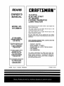
OWNER'SMANUAL
®Assembly
Operation
"Customer Responsibilities
Service and Adjustments
®Repair Parts
\
\
CAUTION:
Read and follow all safety rules and instructions
before operating
this equipment.
FOR CONSUMER ASSISTANCE HOT 1.1NE,CALL THIS TOLL FREE NUMBER: 1--800-659-5917
.
"
'''1'111'1'11'11'1
']'11]
......
III IIII II IIIIIIII
IIIIi
'111
IIIIIIIII
_ IIIII
SAFETY RULES
_
Safe Operation Practices for Ride-On Mowers
IMPORTANT:
THIS CUTTING MACHINE IS CAPABLE OF AMPUTATING HANDS AND FEET AND THROWING OBJECTS_
FAILURE TO OBSERVE THE FOLLOWING SAFETY tNSTRUCT!ONS COULD RESULT IN SERIOUS INJURY OR DEATH°
I.
•
=
o
.
°
o
•
o
°
o
•
o
•
o
iI.
GENERAL OPERATION
Read, understand, and follow all instructionsin the manual
and on the machine before starting.
Only allow responsible adults, who are familiar with the
instructions,to operate the machine_
Clear the area of objects such as rocks, toys, wire, etco,
which could be picked up and thrown by the blade,,
Besure the area isclear of otherpeopfebefore mowing, Stop
machine if anyone enters the area°
Never carry passengers_
Do notmow in reverse unlessabsolutelynecessary, Always
look down and behind before and while backing.
Be aware of the mower discharge directionand do notpoint
it at anyone., Do not operate the mower without either the
entire grass catcher or the guard in place.
Slow down before turning.
Never leave a running machine unattended. Always turnoff
blades, set parking brake, stop engine, and remove keys
before dismounting,,
Tum off blades when not mowing,,
Stop engine before removing grass catcher or unclogging
chute°
Mow only in daylight or good artificiallight°
Do not operate the machine while under the influence of
alcohol or drugs_
Watch for trafficwhen operating near or crossingreadways_
Use extra care when loading or unloadingthe machine into
a trailer or truck.
III.
CHILDREN
Tragic accidents can occur if the operator is not alert to the
presence of children. Children are often attracted to the
machine and the mowing activity. Never asstime that
children will remain where you last saw them_
.
Keep childrenoutof the mowingarea and under the watchful
care ol another responsible adult.
•
Be alert and turn machine off if children enter the area,
°
Before and when backing, look behind and down for small
chi[dreno
°
•
°
Never carry children_ They may fall off and be seriously
injured or interfere with safe machine operation,,
Never allow children to operate the machine_
Use extra care when approaching blind comers, shrubs,
trees, or other objects that may obscure viston,,
W. SERVICE
o
°
o
SLOPE OPERATION
•
Slopes are a major factor related to loss-of-control and
tipover accidents, which can result in severe injury or deatho
All slopes require extra caution. If you cannot back up the
s!ope or if you feel uneasy on it, do not mow it.
DO:
•
Mow up and down slopes, not across,
°
Remove obstacles such as rocks,tree limbs, etc,,
,,
Watch for holes, ruts, or bumps. Uneven terrain could
overturn the machine. Ta// grass can hide obstac/es,,
°
Use slowspeed. Choose a lowgear sothat youwill nothave
to stop or shift while on the slope.
°
Follow the manufacturer's recommendations for wheel
weights or counterweights to improve stability,
°
Use extra care with grass catchers or other attachments,,
These can change the stabilityof the machine.
•,
Keep al! movement on the slopes s/ow and gradua/o Do not
make sudden changes in speed or direction.
°
Avoid starting or stopping on a slope,, tf tires lose traction,
disengage the blades and proceed slowly straightdown the
s!ope.
DO NOT:
.
Do notturnon slopesunlessnecessary, and then, turnslowly
and gradua!]ydownhill,if possible, '
.
Do not mow near drop-offs,ditches, or embankments. The
mower could suddenly turn over if a wheel is over the edge
of a cliffor ditch, or if an edge caves in,
o
Do not mow on wet grass. Reduced tractioncould cause
sliding°
°
Do not tryto stabilize the machine byputtingyourfoot on the
ground°
.
Do not use grass catcher on steep slopes.,
°
•
°
°
°
•
Use extra care in handlinggasolineand other fuels. They are
flammable and vapors are exptostva.
Use only an approved container°
Never remove gas cap or add fuel with the engine
running. Allow engine to cool before refueling,, Do not
smoke.
Never refuel the machine indoors_
Never store the machine or fuel container inside where
there is an open flame, such as a water heater.
Never run a machine inside a closed area.
Keep nutsand bolts,especially blade attachment bolts, tight
and keep equipment in gooa condition,
Never tamper with safety devices.
Check their proper
operation reguladyo
Keep machine free of grass, leaves, or other debris build-up,,
Clean oll or fuel spillage_ Allow machine to cool before
storing°
Stop and inspect the equipment if you strike an object°
Repair, if necessary, before restarting,
Never make adjustments or repairs with the engine running.
Grasscatchercomponents are subjectto wear, damage, and
deterioration, which could expose moving parts or allow
objects to be thrown. Frequently check components and
replace with manufacturer's recommended parts, when necessary.
Mower blades are sharp and can cuL Wrap the blade(s) or
wear gloves, and use extra cauUonwhen servicing them,=
Check brake operation frequently,_ Adjust and service as
required,,
Look for this symbol to point out im- ..............
!
portent safety precautions.
It means
I
CAUTION!t! BECOMEALERTIII
SAFETY IS INVOLVED.,,
i]_1
],
YOUR
|
|
,
spark plug in order to prevent accidental
wire and place wire where it cannot contact
starting when setting up, transporting,
adjusting or making repairs.
.....
....
.............
,
iii,
e
2
I
I
I
J
iii,
,,i,ii
,
A
i[i
I
i_
WARNING
The
ng'ne exhaust from thi=s product contains cnemmais Known to the State of Cadtornia to cause cancer, birth defects, or other
reproductive harm. ,.......
..:.- .'_ .... ._
,,,,,
.._.'_._'_'
- .-
, ,r. j
,i
CONGRATULATIONS
on your purchase of a Sears
Tractor. It has been designed, engineered and manufactured to give you the best possible dependability and
performance,
Should you experience any problem you cannot easily
remedy, please contact your nearest Sears Authorized
Service CentedDepartment, We have competent, welltrained technicians and the proper toolsto service or repair
this tractor,
Please read and retain this manual. The instructions will
enable you to assemble and maintain your unit properly.
Always observe the "SAFETY RULES".
MODEL
NUMBER
917_2585t0
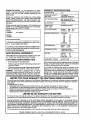
PRODUCT SPECgFOCATIONS
HORSEPOWER:
14o5
GASOLINECAPACITY
AND TYPE:
1.25 Gallons
UNLEADED REGULAR
OIL TYPE (API-SF/SG):
SAE30 (above 32°F)
SAE 5W-30 (below 32°F)
OIL CAPACITY:
3 PINTS
SPARKPLUG:
(GAP: o030")
CHAMPION RJ19LM
VALVE CLEARANCE:
INTAKE: ,O05"_ .007=
EXHAUST: .009" - .011"
GROUND SPEED(MPH):
FORWARD:
1st
2rid
3rd
4th
5tti
6th
REVERSE:
SERIAL
NUMBER
DATE OF PURCHASE
THE MODEL AND SERIAL NUMBERS WILL BE FOUND
ON A PLATE UNDER THE SEAT.
YOU SHOULD RECORD BOTH SERIAL NUMBER AND
DATE OF PURCHASE AND KEEP IN A SAFE PLACE
FOR FUTURE REFERENCE.
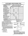
MAIINTENANCE AGREEMENT
=
=
RESPONSIBILITIES
1o0
1.3
2.1
3,,1
4°0
5.1
1.,6
,
TIRE PRESSURE:
FRONT: 14 PSI
REAR: 12 PSI
CHARGINGSYSTEM:
3 AMPS BATTERY
5 AMPS HEADLIGHTS
BATTERY:
AMPPHR:
25
MIN,,CCA:
190
CASE SIZE: U1R
BLADE BOLTTORQUE:
30-35 FT. LBS"
A Sears Maintenance Agreement is available on this product. Contact your nearest Sears store for details.
CUSTOMER
'
Read and observe the safety rules.
Followa regutar schedule in maintaining,caring for and
using your tractor°
with a spark arrester meeting applicable local or state laws
(if any). If a spark attester is used, it should be maintained
in effective working order by the operator.
Followthe instructionsunder"Customer Responsibilities" and "Storage" sections of this owner's manual.
WARNING;
This tractor is equipped with an internal
combustionengine and should not be used on or near any
unimproved forest-covered, brush-covered or grass-covered land unlessthe engine's exhaust system is equipped
In the state of Califomia the above is required by law
(Section 4442 of the California Public Resources Code),
Other states may have similar taws. Federal laws apply on
federal lands, A spark arrester for the muffler is available
through your nearest Sears Authorized Service:Center/
Department (See REPAIR PARTS section of this manual)°
o
LIMITED TWO YEAR WARRANTY ON CRAFTSMAN
RIDING EQUIPMENT
Fortwo (2) yearsfromthe date of purchase,ifth_sCraftsmanRidingEquipmentis maintained,lubricatedand tunedup according
tothe instructions
in the owner'smanual,Searswillrepatror replace,free of charge,any partsfoundtobe defectivein material or
workmanship.
ThtsWarrantydoesnot cover.
°
Expendableitemswhichbecome womduringnormaluse,suchas blades,sparkplugs,aircleaners,belts, etc.
• Tire replacementor repaircausedby puncturesfrom outsideobjects,suchas nails,thorns,stumps,or glass.
o Repairsnecessarybecauseofoperatorabuse,negligence,
improperstorageor acctdentor thefailureto maintainthe
equipmentaccordingto theInstructionscontained inthe owner'smanual,,
•
Riding equipmentusedfor commercialor rentalpurposes_
LIMITED 90 DAY WARRANTY ON BATTERY
For ninety (90) daysfrom date of purchase,if any battery includedwith this ddingequipmentprovesdefectivein material or
wod_nanshipand ourtestingdeterminesthe batterywillnotholda charge,Searswill reptacethebattery at no charge_
IN-HOME WARRANTY SERVICE ON YOUR CRAFTSMAN RIDING EQUIPMENT IS AVAILABLE AT NO-CHARGE FOR 30
DAYS FROM THE DATE OF PURCHASE. PLEASE CONTACT YOUR NEAREST SERVICE CENTER. AFTER 30 DAYS FROM
THE DATE OF PURCHASE, WARRANTY SERVICE IS AVAILABLE BY TAKING YOUR CRAFTSMAN RIDING EQUIPMENT TO
YOUR NEAREST SEARS SERVICE CENTER. (IN-HOME WARRANTY SERVICE WILL STILL BE AVAILABLE AFTER 30 DAYS
FROM THE DATE OF PURCHASE BUT A STANDARD TRIP CHARGE WILL APPLY'.) THIS WARRANTY APPLIES ONLY
WHILE THIS PRODUCT IS IN THE UNITED STATES°
This Warranty gives you specific legat rights, and you may also have other rightswhich may vary from state to state,,
SEARS, ROEBUCK AND CO. D/817 WA, HOFFMAN ESTATES, IL 60179
....
"
_....
.. _..... l lll,
i
,.m
i_ I
lll'l'll'l'l'l
i... i..i.l..i.l.,.i
i.ll.............
_ ._.......
_ ..........
i I'
i
II
TA
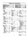
OF CONTENTS
SAFETY RULES ............................................................ 2
PRODUCT SPECIRCATIONS ...................................... 3
CUSTOMER RESPONSIBILITIES ..................... 3, 17-20
WARRANTY ..................................................................
3
TRACTOR ACCESSORIES .......................................... 5
ASSEMBLY .............................................................. 7-10
OPERATION ..................................... ...................... 11-14
MAINTENANCE
SCHEDU_
......
it ...............................
17
SERVICE AND ADJUSTMENTS
................... ,........ 21-26
STORAGE =*_=_m*='_WinWWH_W_I_wlnW_H_=,_W_w._Ht
"
-"_17
WUnmH_m_WmD_Hlt
TROUBLESHOOTING
............................................
28-29
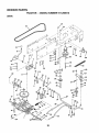
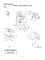
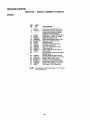
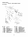
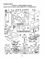
REPAIR PARTS - TRACTOR .....................
........... 32-47
REPAIR PARTS - ENGINE ..................................
..48-55
PARTS ORDERING/SERVICE
........... :.... BACK COVER
INDEX
A
E
Accessodes .............................................. 5
Adjustments:
Brake............................................ 23
Carburetor o_...................=.................26
Mower
Front=To-Back........................... 22
Side-To-Side ............................. 22
Throttle Control Cable ..o:.............. 26
Air Filter, Engine ................................ 19-20
Air Screen, Engine .................................20
Assembly ........................................... 7-10
Electrical:
Interlocks and Relays ................... 25
Schematic ...................................... 31
Wiring Diagram ............................ 32
Engine:
Air Filter...........................................
19-20
Air Screen ..................................... 20
Cooling Rns .......................................
20
Oil Change ...................................... 19
Oil Level ......................................... 14
Oil Type .................................. 14, 19
Preparation .................................... 13
Repair Paffs .............................. 32-49
Starting............................................ 15
Storage .............. _.......................... 27
B
Battery:.
F
Installation ...................................... 8
Levels .......................................... 9,t8
Preparation .........................................8
Starting with Weak Battery .......... 24
Storage ........................................... 27
• Terminals .........................................18
Belt:
Motion Drive
RemovaVReplacement ........... 23
Mower Belt(s)
Removal!Replacement ........... 23
Blade:
Sharpening ................................,ooo18
Replacement ................................ 18
Brake Adjustment ................................. 23
C
Carburetor Adjustment .............................
26
Controls, Tractor .....................................t2
Customer Responsibilities ............. 17-20
Engine:
Air Filter ...................................... 19
Air Screen ................................ 20
Cooling Fins ............................. 20
Engine Oil ............................ 14,19
Fuel Filter ................................. 20
Spark Plug(s) ................................
20
Tractor:.
Battery........................................ t8
Blade ....: .................................... t8
Lubrication Chaff .........................17
Maintenance Schedule ............ 17
Tim Care ............................
10,18, 24
Transaxle .................................. 19
CuMing Height, Mower .......................... 13
Riten
Air Filter............................................19
Fuet ................................................. 20
Fuel:
Type ............................................... 15
torage ..................................................
27
Fuse ........................................................ 25
H
Hood RemovaYlnstallation ......................25
L
Leveling Mower Deck .......................... 22
Lubrication:
Chart ............................................... 17
Engine ..............................................19
ivi
Maintenance Schedule ..........................22
Mower:.
Adjustment, Front-to-Back ........... 22
Adjustment, Side-to-Side .............. 22
Blade Replacement ...................... 18
Blade Sharpening .......................... 18
Cutting Height ................................ 13
Installation ...................................... 21
Operation ........................................ 14
Removal ......................................... 2t
Mowing Tips ............................................ 15
Muffler ............................................................
20
Spark An'ester ............................ 3,42
O
Oil:
Cold Weather Conditions ......... 15,19
Engine ......................... :................. 19
Storage .................................. :ooo.:o.
27
Operation ........................................ 10-14
Operating Mower ................................. 13
Options:
Accessories .................................... 5
Spark Attester .................................. 3
P
Parking Brake .......... ,.................... ,12,13
Parts Bag .............................................. 6
Parts, Reptacemer,.VRepair ............. 32-49
Product Specifications.......................... 3
,
R
Repair Parts ...................................
32-49
S
Safety Rules ...................................... _,,.o2
Seat ......................................................... 8
Service and Adjustments ............... 21-.26
Carburetor .................................. :. 26
Fuse .................. ,............ :............. 25
Hood Removal/installation ........... 25
Motion Drive Belt
Remover/Replacement ........... 23
Mower Belt(s)
Removal/Replacement ............ 23
Mower Adjustment
Front-to-Back ................ .......... 22
Side-to-Side ............................ 22
Mower Removal/installation ......... 21
Tire Care ............................ 10,18,24
Slope Guide Sheet ............................. : 57
Spark Plug(s) ........................................ 20
Specifications................................... o:...... 3
Slatting the Engine ........................ 14-15
Steering Wheel ................................. 7, 24
Stopping the Tractor ........................... 13
Storage ................................................. 27
T
Threttte Cohtrol Cable Adjustment ...... 26
Tires ..................... ..................... 10, 18, 24
Trouble Shooting Chart ................... 28-29
Transaxle ...................................... ;.......19
W
4
Warranty ................................................... 3
Wiring Diagram ...................;................. 32
Wiring Schematic ................................. 31
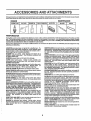
AND ATTAC
ENTS
These accessories and attachments wereavailable throughmost Sears retail outletsand servicecenters when the tractor was purchased,
Most Sears stores can order these items for you when you provide the model number of your tractor.
ENGINE
SPARK PLUG
MAINTENANCE
GAS CAN
ENGINEOIL
FUEL STABILIZER
AIR FILTER
BLADES
BELTS
w,
PERFORMANCE
Sears offers a wide variety of attachments that fit your tractor. Many of these are listed belowwith briefexplanations of how they can help
you. This listwas current at the time ol publication;however, it may change in future years - more attachments may be added, changes
may be made in these attachments, or some may no longer be available or fit your model Contact your nearest Sears store for the
accessories and attachments that are available for your tractor.
Most of these attachments do not require additiona_hitches or conversion kits (those that do are indicated) and are designed for easy
attaching and detaching.
AERATOR promotes deep root growth for a healthy lawn. Tapered 2.5-inch steel spikes mounted on t0_inch diameter discs
puncture holes in soil at close intervals to let moisture soak in°
Steel weight tray for increased penetration,
BAGGER lets you collect grass clippings and leaves for.a
healthier, heater looking tawn_ Two Permartex containers hold
30-gallon plastic bags.
BUMPER protects front end of tractorfrom damage°
CARTS make hauling easy° Variety of sizes available, plus
accessories such as side panel kits, tool caddy, cart cover,
protective mat and doily.
CORING AERATOR takes small plugs out of soil to allow roofs.
lure and nutrients to reach grass roots. 36-inch swath° 24
hardened steel c0dng tips. 150 lb. capacity weight t_ay.
EASY OIL DRAIN VALVE makes oil changes easier, faster.
FRONT NOSE ROLLER canters infrontof mower deck toreduce
chances of =scalping _ on uneven terrain_
GANG HITCH lets youtow 2 or3 puIFbehindattachments at once,
such as sweepers, dethatchers, aerators (not for use with rollers,
carts or other heavy attachments).
GAUGE WHEELS on both sides of the mower deck reduce
chances of =scalping"on uneven terrain° For mower decks not so
equipped°
MULCH RAKE/DETHATCHER loosenssoil and flips thatch and
matted leaves to lawn surface for easy pickup. Twenty springttne
teeth. Useful to prepare bare areas forseeding. Available forfront
or rear mounting. HIGH PERFORMANCE REEL-ACTION
SPRING TINE DETHATCHER covers 36-inch wide path and
tosses thatch into large hopper_ Mounts behind tractor.
MULCHING CLOSE-OUT PLATE KIT, once installed, lets you
mulch, discharge or bag clippings (bagger optional) without
changing blades=_For models not equipped as 3-in_l Convertible
mowers. See MOWER in the Repair Parts section ot this
manual
SNOW BLADE for snowremoval only. 14-inch high, 48-inch wide
blade clears42-inch pathwhen angledteft ordght. Raises, lowers
Withside lever. Adjustableskids; replaceable, reversible scraper
bar. (Use with tirechains and wheel weights and/or rear drawbar
weight.)
SNOWTHROWER has 40-inchswath. Drum-type augerhandles
powdery and wet/heavy snow, Mounts easily with simple pin
arrangement. Discharge chute adjusts from tractor seat. 6-inch
diameter spout discharges snow 10 to 50 feel Lift controlledat
tractor seal (Use with chains and wheel weights and/or rear
drawbar weight.)
SPRAYERS use 12-voft DC electric motor that connects to the
tractor battery or other 12-volt source° Includes booms for
automaticsprayingand hand heldwand for spot spraying. Wand
has adjustable spray pattern. For applying herbicides, insecticides, fungicides and liquid fertilizers_
SPREADEWSEEDERS make seeding_fertilizing, and weed killing easy. Broadcast spreaders are also useful for granular detcers and sand°
SWEEPERS let you collect g_ss ciippings and leaves
TILLER has 5 hp engine and 36-inch swath to prepare seed beds,
cultivate and compostgarden residue. Tiller has its own built-in
liftand depth controlsystem and does NOT require a sleeve hitch°
Fitsanylawn, yard or garden tractor. Simply hook up tothe tractor
drawbar and gol
Optional accessories
convert unit for
dethatching, aerating, hilling...without tools.
TIRE CHAINS are heavy duty; c_osetyspaced extra-large cross
links gtve smooth ride, outstanding tracbono
TRACTOR CAB has heavy duty vinyl fabric over tubular steel
frame, ABS plastictop; clear plasticwindshield offers360 degree
visibility. Hinged metal doors With catch. Keeps operator warm
and dry. Remove vinyl sides and wir_dshteldsfor use as sun
protector in summer. Optional accessories include, tinted/
tempered solidsafety glass windshield with hand operated wiper;,
12-volt amber caution light for mounting on cab top_
VACS tor powedui collectionof heavy grassclippings andteaves_
Optional wand attachment to pick up debris in hard-to-reach
places, VAGICHIPPER includes a chipper-shredder.
WEIGHT BRACKET for drawbar for snow removal applications,
Uses (t) 55 lb_weight.
WHEEL WEIGHTS for rear wheels provide needed traction for
snow removal or dozing hea_rymaterials_
RAMP TOPS AND FEET let you load and unload tractorfrom a
pickup truck. Use with 2 x 8 or 2 x 10 lumber_
ROLLER for smoother tawn sufface. 36-inch wide, 1S-inch
diameterwater-tight drumholdsup to390 lbs,of weight. Rounded
edges prevent harm to tuff, Adjustable scraper automatically
cleans drum.
5
,_1_1111
,,
CONTENTS
,,_
,,i
,, ,,, ,i,,
,
_1
1,1,1,i
....................
OF
i........
_,:
E PACK
,,,,,,,
,,,,,,,,,,,,,,
...........................
i, ,,i,ii1,11
,, I,
,,i
i
,
,I,,,,,,,,F,,_,_
.....
..........
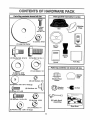
Pads Bag contents
rH rl
,,,11 •
I'
, ,i,,,, ..,..........
_,_ ,:j_
_;;,r',
....
shown full size
Parts
packed
separately
in carton
ii
....i,,,,i,.,.:.,,,
.....j,,
Mulcher
Plate
(2) Sheet
Seat
Screws
Metal
#10-16
x 1/2
O
(1) Locknut 3/B-24
(1) Large Flat Washer
,ll
(1) Shoulder Bolt 5/16-18
V_deo
Cassette
Steering
Wheel
ii.......
Steering
Boot
(1) Hex Bolt 1/2_13x I
Parts Bag
Manual
I'11'
:
,
i .....
,_i
r',_
..............
Parts bag contents
,1' ,,i
.....
,,;,,;
not shown full size
(1) Lock Washer 112
j: m
(1) Washer 17/32
x 1-3t16 x 12 Gauge
@
uJ_wi ill
(2) Washers
Steering
Wheel
insert
Steering Wheel
Adapter
(2) Lock Washers #10
3/16 x 3/4 x 16 Gauge
___
(2) Weld Nuts #10
(2) Keys
Bushing
Steering
(_
(2) Screws #10 x 5/8
Hill
IIII
'11
I
(2) Hex Bolts 1/4-20 x 3/4
qlPqlll" I
I'
(2) Hex Nuts 1/4-20
(2) Latch Hook
Assemblys
Slope Sheet
(2) Lock Washers
1/4
,!!,,
(2) Washers 9/32 x 5/8 x 16 Gauge
6
!i,i
,
i
!
II
,
iL
I
I
I
BLY
Your new tractor has been assembled at the factory with exception of those parts left unassembled for shipping purposes.
To ensure safe and proper operation of your tractor all parts and hardware you assemble must be tightened securely. Use
the correct tools as necessary to insure propePtightness.
TOOLS REQUURED FOR ASSEMBLY
. STEERING WHEEL INSERT
A socket wrench set will make assembly easier,, Standard
wrench sizes are listed.
(1) 5/16" wrench
(1) 314"wrench
(2) 7/16" wrenches
Tire pressure gauge
(1) 1/2" wrench
Utility knife
.__3/8-24
(1) phillipsscrewdriver
(1) 9/16" wrench
When right or left hand is mentioned in this manual, it
means when you are in the operating position (seated
behind the steering wheel)_
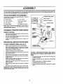
STEERING
TO REMOVE TRACTOR FROM CARTON
WHEEL
ADAPTER _
UNPACK
STEERING
•
o
•
LOCKNUT
'\__;7/
CARTON
\
STEERI.G
"......._ __T_ \v
j,"
BUSHING
SHEET
METAL
SCREW
TABS
_
°o;:L' oo.,o
Remove all accessible loose parts and parts cartons
from carton (See page 6),
Cut, from top to bottom, along lines on all four comers
of carton, end lay panels flat,
Check for any additional loose parts or cartons and
remove°
(ASSEMBLY
PosmoN)
SLOT
BEFORE ROLLING TRACTOR OFF SKiD
t
p
ATTACH
°
°
STEERING
Position steering boot over steering shaft,
Place tabs of steering boot over tab slots in dash and
push down to secure.
.
°
Slide steering wheel adapter ontoupper steering shaft°
Positionfront wheels of the tractor so they are pointing
straight forward,
Position steering wheel so cross bars are horizonta!
(left to right) andsfide onto adapter,
°
°
STEERING SHAFT
(SHIPPING POSITION)
Slide the steering bushing over the steering shaft.
Raise steering shaft forward until screw holes in dash
line up with steering bushing, Install two (2) sheet
metal screws and tighten securely,
o
-
°
t :
WHEEL (See Fig. 1)
FIG. 1
TO ROLL TRACTOR OFF SKID (See Operation section for location and function of controls)
Assemble large flat washer and 3/8-24 locknut and
tighten securely_
Snap steering wheel insert into center of steering
wheel.
°
Press lift lever plunger and raise attachment liftlever to
its highest position,
•
Release parking brake by depressing clutch/brake
pedal.
Place gearshift lever in neutral (N) position.
Roll tractor backwards off skid.
•
•
°
•
Remove protective plastic from tractor hood and grill°
IMPORTANT:CHECK FOR AND REMOVE ANY STAPLES
IN SKID THAT MAY PUNCTURE TIRES WHERE TRACTOR
IS TO ROLL OFF SKID.
7
Remove banding holding discharge guard up against
tractor,
BLY
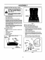
CONNECT
BATTERY
(See Figs. 2 and 3)
CAUTION: Do not short battery terminals. Before connecting battery, remove metal bracelets, wristwatch
bands, rings, etc.
SEAT
PAN
Positive terminal must be connected
first to prevent sparking from accidental grounding ....
°
Remove cardboard pecking from seat pan and lift seat
pan to raised position.
,,
=
Open battery box door.
Remove terminal protective caps and discard.
,,
tf this battery is put into service after month and year
indicate_lon label (label located between terminals)
charge battery for minimum of one hour at 6-10 ampso
°
Firstconnect RED battery cable to positive(+) terminal
with hex bolt, flat washer, lock washer and hex nut as
shown. Tightensecurelyo
o
°
BATTERY
BOX DOOR
RG. 3
INSTALL SEAT (See Fig. 4)
Connect BLACK groundingcable to negative (-) terminal with remaining hex bolt, flat washer, lock washer
and hex nut. Tighten securely.
Close battery box door.
Adjust seat before tighteningadjustment bolt.
Open battery box door for:.
o
o
Inspection for secure connections (to tighten hardware).
Inspection for corrosion.
°
Testing battery.
•
Jumping (if required).
°
Pedodic charging.
PosmvE
DISCARD TERMINAL PROTECTIVE
CAPS
/
IRED) CABIE_
_
NUT
HEX
vt
o
Remove cardboard packing on seat pan.
°
o
Place seat on seat pan and assemble shoulder bolt.
Assemble adjustment bolt, lock washer and flat washer
loosety_ Do not tighten.
'
'
,
°
Tighten shoulder bolt securely.
Lower seat into'operatingposition and sit on seat.
•
Slideseat until a comfortableposition is reached which
allows you to press clutch/Drake pedal all the way
down.
•
Get off seat without moving its adjusted position.
°
Raise seat and tighten adjustment bolt securely.
SEAT
WASHER
LOCK
FLAT
WASHER
SEAT PAN
SHOULDER
BOLT
BOLT
NEGATIVE
(BLACK)CABLE
FIG. 2
FLAT WASHER
ADJUSTMENT
BOLT
LOCK WASHER
FIG. 4
8
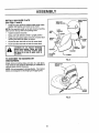
iNSTALL IVIULCHER PLATE
(See Figs. 5 and 6)
HOOK POINTS
WELD NUT
•
Install two latch hooks to mulcher plate using screw,
washer, lock washer, and weld nut as shown°
NOTE: Preoassembfe weld nut to latch hook by inserting
weld nut from the top with hook pointing down°
o
°
Tighten hardware securely.
Raise and hold deflector shield in upright position.
•
Place front of mulcher plate over front of mower deck
opening and slide into place, as shown,
Hook front latch into hole on front of mower deck.
o
o
LOCK
WASHER
LATCH
HOOK
HOOK
Hook rear latch into hole on back of mower deck.
LOOK
WASHER
CAUTION: Do not remove discharge
guard from mower. Raise and hold
guard when attaching mulcher plate
and allow it to rest on plate while in
operation.
.......
TO CONVERT
III1'
TO BAGGING
w,s.
WASHER
MULCHER
PLATE
III
WELD
NUT
\_'_SCREW
OR
FIG. 5
DISCHARGING
Simply remove mulcher plate and store in a safe place.
Your mower is now ready for dischargingor installationof
optional grass catcher accessory.
NOTE: it is not necessary to change blades. The mulcher
blades are designed for discharging and bagging also.
DEFLECTOR
SHIELD
HOOKS
FIG. 6
9
J CHECKLIST
CHECK TIRE PRESSURE
BEFORE YOU OPERATE AND ENJOY YOUR NEW
TRACTOR, WE WISH TO ASSURE THAT YOU RECEIVE
THE BEST PERFORMANCE AND SATISFACTION FROM
T/-I/S QUALITY PRODUCT°
The tires on your tractorwere ovednflatedat the factory fo_"
shipping purposes. Correct tire pressure is important for
best cutting performance.
o
Reduce tire pressure to PSI shown in "PRODUCT
SPECIFICATIONS" on page 3 of this manual
PLEASE REVIEW THE FOLLOWING CHECKLIST:
CHECK DECK LEVELNESS
For best cutting resutts,mower housing shouldI_eproperly
leveled. See =TO LEVEL MOWER HOUSING" in the
Service and Adjustments section of this manual
CHECK
BELTS
FOR
PRORER
POSITION
J'
All assembly instructionshave been compfeted_
J
No remaining loose parts in carton.
v"
Battery is propedy prepared and charged. (Minimum
1 hour at 6 amps)o
Seat is adjusted comfortably and tightened securely.
4
OF ALL
4
All tires are properly inflated. (For shipping purposes,
the tires were overinflated at the factor,/).
,/" Be sure mower deck is properly leVeled side-to-side/
front_to_rear for best cutting results. (Tires must be
properly inflated for leveling).
/
Check mower and ddve belts. Be sure they are routed
properly around pulleys and inside all belt keepers.
Check wiring. See that all connections are stillsecure
and wires are properly clamped.
WHILE LEARNtNG HOWTO USE YOUR TRACTOR, PAY
EXTRA A TTENTION TO THE FOLLOWING IMPORTANT
ITEMS:
See the figures that are shown for replacing motion and
mower blade drive belts in the Service and Adjustments
section of this manual. Verify that the belts are routed
correctly.
CHECK BRAKE SYSTEM
After you learn how to operate your tractor, check to see
that the brake is properly adjusted. See =TO ADJUST
BRAKE" in the Service and Adjustments section of this
manual.
v"
,/'
v"
,!
10
Engine oil is at proper level.
Fuel tank is filled with fresh, clean, regular unleaded
gasoline.
Become familiar With all controls - their location and
function° Operate them before you start the engine.
Be sure brake system is in safe operating condition.
OPERATUON
,
m ..........................................
These symbols may appear
....;.,,,,
•................
............................
on your tractor or in literature supplied with the product.
Learn and understand
,,,,,,,,,,,,,,
their meanlngo
BATTERY
CAUTION OR
WARNING
REVERSE
FORWARD
FAST
SLOW
ENGINE ON
ENGINE OFF
OIL PRESSURE
CLUTCH
LIGHTS ON
LIGHTS OFF
FUEL
CHOKE
MOWER HEIGHT
DIFFERENTIAL
LOCK
PARKING BRAKE
LOCKED
UNLOCKED
L
REVERSE
MOWER LIFT
NEUTRAL
ATTACHMENT
CLUTCH ENGAGED
HIGH
LOW
ATTACHMENT
CLUTCH DISENGAGED
PARKING BRAKE
IGNITION
HYDROSTATIC FREE WHEEL
(Hydro Models only)
DANGER, KEEP HANDS AND FEET AWAY
11
m,
_prrlrrrrrr;rrrrrrm_Tr
_
.....
..........................
,_Mj
[ i
li t .................
OP
KNOW YOUR TRACTOR
READ
THIS
OWNER'S
MANUAL
AND SAFETY
RULES
BEFORE
OPERATING
YOUR
TRACTOR
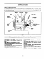
Compare the illustrationswith your tractorto familiarizeyourself withthe locationsofvarious controlsand adjustments, Save
this manual for future reference,
,,_
AMMETER
LIGHT
SWITCH
IGNITION
_
SWITCH
LIFT LEVER
PLUNGER
THROTTLFJ
CHOKE
CONTROL
ATTACHMEkrr
UFT LEVER
i
CLUTCW
BRAKE
PEDAL
MOWER DECK
HEIGHT ADJUSTMENT
PARKING
BRAKE
GEARSHIFT
LEVER
FIG. 7
Our tractors conformto the safety standards of the American National Standards Institute_
ATTACHMENT CLUTCH LEVER: Used to engage the
mower blades, or other attachments mounted to your
tractor.
GEARSHIFT LEVER: Selects the speed and direction of
tractor.
ATTACHMENT MFT LEVER: Used to raise, lower, ancl
adjust the mower deck or other attachments mounted to
your tractor°
LIFT LEVER PLUNGER: Used to release attachment lift
lever when changing its position.
IGNITION SWITCH: Used for starting and stopping the
engine°
AMMETER: Indicates batter:/charging (+) or discharging
UGHT SWITCH: Turns the headlights on and off_
THROTTLE/CHOKE CONTROL: Used for starting and
controll!ng engine speed.
CLUTCH/BRAFJE PEDAL: Used for declutchingand braking the tractor and starting the engine.
PARKING BRAKE: Locks clutch/Drake pedal into the
brake position.
12
ATUON
-, ............
"
::_
"
:-: .......
::-,,_ :
' "
_
¸:¸:............
,,,j,_l,,ll,,i
,_,
,,I
,,i,,,,=l,i ,,
ii1_1,_,_l,_ll,
The operation of any tractor can result in foreign objects thrown into the eyes, which
can result in severe eye damage. Always wear safety glasses or eye shields while
operating your tractor or performing any adjustments Orrepairs. We recommend awide
vision safety mask over the spectacles or standard safety glasses.
...........
.............,,,,,,
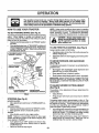
Yourtractor isequipped with an operatorpresence sensing
switch° When engine is running, any attempt by the
operator to leave the seat without first setting the parkirig
brake will shut off the engine.
,
Depress clutch/brake pedal intofull =BRAKE" position
and holdo
_ ENGAGED
TO USE THROTTLE
o
Operating engine at less than full throttle reduces the
battery charging rate.
TO MOVE FORWARD
(See Fig. 8)
CONTROLLEVER
GEAR-
° Move gearshift lever to desired position.
•
Slowly release clutch/brake pedal to start movement.
IMPORTANT: BRING TRACTOR TO A COMPLETE STOP
BEFORE SHIFTING OR CHANGING GEARS. FAILURE
TO DO SO WILL SHORTEN THE USEFUL LIFE OF YOUR
TRANSAXLE.
LEVER
(
__.
SHIFT
"BRAKE=
POSITION
TO ADJUST MOWER CUTTING
(See Fig. 8)
\
CLUTCH/BRAKE PEDAL
"DRIVE = POSITION
HEIGHT
The position of the attachment lift lever determines the
cutting height.
PARKING BRAKE
"DISENGAGED"
PosmoN
FIG. 8
•
•
(See Fig. 8)
MOWER BLADES ° Move attachment clutch lever to "DISENGAGED" position.
GROUND DRIVE ° Depress clutch/brake pedal intofull"BRAKE"position.
,
Move gearshift lever to neutral (N) position°
ENGINE Move throttle controlto slow (,€_) position°
NOTE: Failure to move throttle control to slow (,_)
position and allowing engine to idle before stopping may
cause engine to "backfire".
• Turn ignition key to "OFF" position and remove key.
Always remove key when leaving tractor to prevent
unauthorized use,
°
Never use choke to stop engine.
AND BACKWARD
The directionand speed of movement is controlledby the
gearshift lever.
o Start tractor with clutch/brake pedal depressed and
gearshift lever in neutral (N) position.
PARKING
BRAKE
=ENGAGED =
I
t
t
(See Fig. 8)
Full throttle offers the best bagging and mower performance.
IGNITION
KEY
STOPPING
CONTROL
!
Always operate engine at full throttle.
=DISENGAGED"
POSEION
POSITION
!
........
l •
..pletely, as descri ,bedabove, beforeleav._ J I
ing the operator s position; to empty
i ................
, ,
CAUTION: Al'_ays stop tractor"coraU ! II
grass catcher, etc.
Place parking brake lever in"ENGAGED" positionand
releasepressure from crutch/brakepedal Pedalshould
remain ,n"BRAKE" position. Make sure parkingb_'ake
will hold tractor secure.
LA_ACHME_ CLUTCHLEVER
:
NOTE: Under certain conditions when tractor is standing
idlewiththe engine running,hot engine exhaust gases may
cause "browning" of grass. To eliminate this possibility,
always stop engine when stopping tractor on grass areas.
TO SET PARKING BRAKE (See Fig. 8)
°
......:..:::,,,. :_
I
Grasp lift lever.
Press plunger with thumb and move lever to desired
position_
The cutting height range is approximately 1-1/2to 4". The
heights are measured from the ground to the blade tip with
the engine not running. These heights are approximate
and may vary"depending upon soil conditions, height of
grass and types of grass being mowed.
13
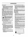
°
The average lawn shouldbe cut to approximately/2-1/2
inches during the cool season and to over 3 inches
during hot months,, For healthier and better looking
lawns, mow often and after moderate growth.
•
For best cutting performance, grass over 6 inches in
height should be mowed twice, Make the first cut
relatively high; the second to desired height,
Your tractor isequipped with an operator presence sens.
ing switch. Any attempt by (he operator to leave the seat
withthe engine running and the attachmentclutchengaged
will shut off the engine.
= Select desired height of cut.
Start mower blades by engaging attachment clutch
control.
_
I
o
°
TO STOP MOWER BLADES - disengage attachment
clutch control.
°
CAUTION: Do not operate the mower
without either the entire grass catcher,
on mowers so equipped, or the dis...........................
charge guard in place.
ATTACHMENT CLUTCH LEVER
"DISENGAGED" POSITION
"ENGAGED"
POSITION
......
ill...........................
I'
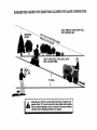
CAUTION: Do not drive up or down
hills with slopes greater than 15 ° and
do not drive across any slope.
Choose the slowest speed before starting up or down
hills.
Avoid stopping or changing speed on hills.
If slowing is necessary, move throttle control lever to
slower position.
If stopping is absolutely necessary, push clutch_rake
pedal quickly to brake position and engage parking
brake.
Move gearshift lever to 1st gear. Be sure you have
allowed room for tractor to roll slightly as you restart
movement.
ATTACHMENT
LIFT LEVER
HIGH POSITION
8
To restart movement, slowly release parking brake and
clutch/brake pedal
O
Make all turns slowly,
TO TRANSPORT
•
Raise attachment lift to highest position with attachment lift contro!.
•
When pushing ortowing yourtractor, be sure gearshift
lever is in neutral (N) position.
•
Do not push or tow tractor at more than five (5) MPHo
NOTE: To protect hood from damage when transporting
your tractor on a truck or a trailer, be sure hood is closed
and secured to tractor. Use an appropriate means of tying
hood to tractor (rope, col'd, etc°).
BEFORE STARTING THE ENGINE
CHECK ENGINE OIL LEVEL (See Fig, 14)
DISCHARGE
GUARD
°
The engine inyour tractor has been shipped, from the
factory, already filled with summer weight oil
•
°
Check engine oil with tractor on level ground.
Remove oilfill cap/dipstick and wipe clean, reinsertthe
dipstick and screw cap tight, wait for a few seconds,
remove and read oil level. If necessary, add oil until
"FULL" mark on dipstick is reached. Do not overfill.
°
For cold weather operation you should change oil for
easier starting (See OIL VISCOSITY CHART" in the
Customer Responsibilities section of this manual).
,
To chan_e engine oil, see the Customer Responsibilities sect=on in this manual
FIG. 9
14
COLD WEATHER STARTING ( 50° F and below)
•
When engine starts, allowengine to run with thethrottie
controlin the choke ([\1) position until the engine runs
roughly,then move throttlecontrolto fast (,_) position.
This may require an engine warm-up per_d from
several seconds to several minutes, depending on the
temperature.
o The attachments can also be used during the engine
warm-up pedodo
NOTE: If at a high altitude (above 3000 feet) or in cold
temperatures (below 32 F) the carburetor fuel mixture may
need to be adjusted for best engine performance. See "TO
ADJUST CARBURETOR" in the Service and Adjustments
section of this manual
ADD GASOLINE
,
Fill fuel tank. Use fresh, clean, regular unleaded
gasoline with a minimum of 87 octane. (Use of leaded
gasoline will increase carbon and lead oxide deposits
and reduce valve life). Do not mix oil with gasoline.
Purchase fuel in quantities that can be used within 30
days to assure fuel freshness°
IMPORTANT: WHEN OPERATING IN TEMPERATURES
BELOW
32_F(0oc),
U=SEFRESH,
CLEANCOLD
WINTER
GRADE
GASOLIr_[o HELP
INSURE GOOD
WEATHER
STARTING°
WARNING: Experience indicates that alcohol blended
fuels (called gasohol or using ethanol or methanol) can
attract moisture which leads to separation and formationof
acids dudng storage. Acidic gas can damage the fuel
system of an engine while in storage. To avoid engine
problems, the fuel system should be emptied before stor_
age of 30 days or longer. Drain the gas tank, start the
engine and let it run until the fuel lines and carburetor are
empty, Use fresh fuel next season_ See Storage instructions for additional information. Never use engine or
carburetor cleaner products in the fuel tank or permanent
damage may occur.
CAUTION: Fill to bottom of gas tank
filler neck. Do not overfill. Wipe off any
spelled oil or fuel. Do not store, spill or
use gasoline near an open flame.
MOWING TiPS
o
Tire chains cannot be used when the mower housing
is attached to tractor.
°
Mower shouldbe properly leveled for best mowing
periormance. :_ee %0 LEVEL MOWER HOUSING in
the Service and Adjustments section of this manual.
The left hand side of mower should be used for trimming.
Drive so that clippings are discharged onto the area
that has been cut. Have the cut area to the right of the
machine. This will resultin a more even distribution of
clippingsand more uniform cutting°
When mowing large areas, start by turning to the right
so that clippings will discharge away from shrubs,
fences, driveways, etc. After one or two rounds, mow
in the opposite direction making left hand turns until
finished (See Fig. 10A).
If grass is extremely tall, it should be mowed twice to
reduce load and possible fire hazard from dried clippin,Is. Make first cut relatively high; the second to the
desired height.
Do not mow grass when it is weL Wet grass will plug
mower and leave undesirable clumps. Allow grass to
dry before mowing.
,
i
i
|
o
°
TO START ENGINE (See Fig. 8)
When starting the engine for the first time or if the engine
has run out of fuel, it will take extra cranking time to move
fuel from the tank to the engine.
o
Depress clutch/brake pedal and set parking brake.
°
-
Place gear shift lever in neutral (N) position.
Move attachment clutch to =DISENGAGED" position°
o
Move throttle controlto choke (N)
o
°
position,.
Note: Before starting, read the warm and cold starting
procedures below.
°
Insertkeyintoignitionand turnkey clockwiseto"START"
positionand release key as soon as engine starts. Do
not run starter continuouslyfor more than fifteen seconds per minute. If the engine does not start after
several attempts, move throttle control to fast (,_)
position,wait a few minutesahd try again. Ifengine still
does not start, move the throttle control back to the
choke (N) position and retry.
•
°
Always operate engine at full throttle when mowing to
assure better mowing performance and proper discharge of material Regulate ground speed by selecting a low enough gear to give the mower cuttlng
performance as well as the quality of cut desired.
When operating attachments, select a ground speed
that will suit the terrain and give best performance of
the attachment being used°
WARM WEATHER STARTING (50 ° F and above)
° When englne starts,move the throttlecontrolto thefast
(,tee)pos!tiono
o The attachments and ground drive can now be used. If
the engine does not accept the load, restart the engine
and allow it to warm up for one minute using the choke
as described above.
<[
FIG. 10A
15
--
....... J
OPERATION
MULCHING
MOWING
TIPS
IMPORTANT:
FOR BEST PERFORMANCE; KEEP
MOWER HOUSING FREE OF BUILT-UP GRASS AND
TRASH. CLEAN AFTER EACH USE.
°
Forbestresults, adjustthemowercuttingheightsothat
the mower cuts off only the top one-third of the grass
blades (See Fig. 10B). For extremely heavy mulching,
reduceyourwidth ofcut on each pass and mow slowly.
=
o
Certain types of grass and grass conditions may require that an area be mulched a second time to
completely hide the clippings. When dotng a second
cut, mow across or perpendicular to the first cut path.
Change your cuttingpattern from week to _veek. Mow
northtosouthone week then change to east towest the
next week. This willhelp prevent matting and graining
of the lawn.
The special mulching blade wi!l recut the grass clippings many times and reduce them in size so that as
they fall onto the lawn they will disperse intothe grass
and not be noticed. Also, the mulched grass wilt
biodegrade quickly to provide nutrientsfor the lawn.
Always mulch with your highest engine (blade) speed
as this will provide the best recutting action of the
blades.
•
Avoid cuttingyour lawn when itiswet. Wet grasstends
to form clumps and interfereswith the mulching action.
The best time to mow'your lawn is the early afternoon.
At this time the grass has dried and the newly cut area
will not be exposed to the direct sun,
FIG, 10B
16
CU
RESPONSUBILUTmES
Check BrakeOperation
_#'
CheckTirePressure
_l'
::
_
T c.;_k,0r_00SeFa,,;ne_
v' :
_l'
...........v'.:
R
Sharpen/ReplaceMowerBlades
_f4
T
CheckBatteryLeveVRecharge
_
Lub_'catiO'"
ch;_.....................
v'
V' .....
, ,_
..... ,,,,
.......................
.....
,, :o : :.....'.
$/
......
A_Juo,
_=o_o,,_°_
_o°o,o.
........................... v',...........
Adjust MotionDriveBelt(s)Tension
Check,EngineOil Level
Ch.ngoE°g,°ool,
.... "
i##s
_
if
, .....
V' ; ._',_,i,0
........
V'.............................
i .....
G
InspectMuffler/SparkAttester
ReplaceOil Filter (ff equipped)
N
E ',,,€iean,,Englne
CoolingFins
_,,
ReplaceSparkPlug
ReplaCeAirFilterPaP'erCa'rtridge
_'
i .......
...............
_,2
_2
Qf
_2
.............
ReplaceFuelFilter
1234-
,
_ .............
0 o,oo° o,o o°0 o=°o,oI :J.......
R :CheckTmS_l;Co_iing
.
Change more often when operating under a heavy load or in high ambient temperatures..
Service more often when operating in dirtyor dusty conditions,,
i! equipped with eli Bier, change oiI every 50 hours
Replace blades mote often when mowing in se,ndy soil
" '_
_#'
.....
_,
.
.
.
5 - If equipped with adjustable systen'L
6 =Not required I! equipped with rr,_nlenance-fme battery,
7 - 33ghten Irant axle pivot bolt to 35 flabs maximum,
Do no! overttghten
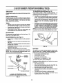
LUBRICATION
GENERAL RECOMMENDATIONS
CHART
(_) SPII
The warranty on this tractor does not cover items that have
been subjected to operator abuse or negligence. To
receive full value from the warranty, operator must maintain
tractor as instructed in this manual.
)INDLE ZERK(_
(_)
BEARING
ZERK
"FRONT WHEEL (_)
BEARING ZERK
Some adjustments will need to be made periodically to
properly maintain your tractor.
®
All adjustments in the Service and Adjustments section of
this manual should be checked at least once each season°
Once a year you should replace the spark plug, clean
or replace asr filter, and check blades and belts for
wear. A new spark plug and clean air filter assure
proper air-fuel mixture and help your engine run better
andtast longer.
BEFORE
PIVOT(S)
EACH USE
=
Check engine oil level.
-
Check brake operation,
°
=
(_ CLUTCH
(_SAE
30 OR IOW30 MOTOR OIL
(_) GENERAL PURPOSE GREASE
Check tire pressure,
Check for loose fasteners,,
(_) REFER TO CUSTOMER RESPONSIBIUTIES
"ENGINE"
SECTION
IMPORTANT:
DO NOT OIL OR GREASE THE PIVOT POINTS
WHICH HAVE SPECIAL NYLON BEARINGS_ VISCOUS LUBRICANTS WiLE ATTRACT DUST AND DIRT THAT WILL SHORTEN
THE LiFE OF THE SELF-LUBRICATING
BEARINGS.
tF YOU
FEEL THEY MUST BE LUBRICATED,
USE ONLY A DRY, POWDERED GRAPHITE TYPE LUBRICANT SPARINGLY,
17
TO SHARPEN
TRACTOR
Always observe safety rules when performing any maintenanceo
BRAKE OPERATION
The blade can be sharpened with a file or on a grinding
wheel Do not attempt to sharpen while on the mower.
If tractor requires more than six(6) feet stopping distance
at high speed in highest gear, then brake must be adjusted°
(See "TO ADJUST BRAKE" in the Service and Adjustments section of this manual).
TIRES
•
To check blade balance, you wilt need a 5/8" diameter
steel bolt, pin, ora cone balancer. ('When using a cone
balancer, follow the instructions supplied with batancer).
•
Slide blade onto an unthreaded porttohof the steel bolt
or pin and hold the bolt or pin parallel with the ground.
If blade is balanced, it should remain in a horizontal
position, if either end of the blade moves downward,
sharpen the heavy end until the blade is balanced.
Maintain proper air pressure in all tires (See "PRODUCT SPECIFICATIONS on page 3 of this manual).
,
Keep tires free of gas61ine, oil, or insect control chemicals which can harm nJbber.
,
Avoid stumps, stones, deep ruts, sharp objects and
other hazards that may cause tire damage.
BLADE (See Fig, 12)
Care should be taken to keep the blade balanced. An
unbalanced blade willcause excessive vibration and eventual damage to mower and engine.
NOTE: Do not use a nail for balancing blade_ The lobes of
the center hole may appear to be centered, but are not.
BLADE CARE
CENTER HOLE
For best results mower blades must be kept sharp, Re_
ptace bent or damaged blades,
BLADE REMOVAL
Raise mower to highest position to allow access to
blades.
,
Remove hex bolt, lock washer and flat washer securing blade.
Install new or resharpened blade with trailing edge up
towards deck as shown°
°
OR PIN _J
Reassemble hex bolt, lock washer and flat washer in
exact order as shown.
, FIG, 12
o Tighten bolt securely (30-35 Ft. Lbs. torque)°
IMPORTANT: BLADE BOLT IS GRADE 8 HEAT TREATED.
BATTERY
Your tractor has a batter':,,charging system which is sufficient for normal use_ However, periodic charging of the
battery with an automotive charger wi!l extend its life.
° Keep battery and terminals clean.
NOTE: We do not recommend sharpening blade - but if
tou do, be sure the blade is balanced.
BLADE
\,
_
ASSEMBLY
°
°
MANDREL
°
Recharge at 6-10 amperes for I hour.
TO CLEAN BATTERY AND TERMINALS
__EX
B_RADE
Keep battery bolts tight.
Keep small vent holes open.
Corrosion and dirt on the battery and terminals can cause
the battery to =leak" power.
TRAIUNG
EDGE UP
LOCK WASHER-
/
(See Fig. 11)
=
o
/
•
•
Open battery box door.
Disconnect BLACK battery cable first then RED battery cable and remove battery from tractor.
•
Rinse the battery with plain water and dry.
°
Clean terminals and battery cable ends with wire brush
until bright.
•
,
Coat terminals with grease or petroleum jelly.
Reinstall battery (See "CONNECT BATTERY" in the
Assembly section of this manual).
8)*
*A GRADE 8 HEAT TREATED BOLT CAN BE
IDENTIRED BY SIX LINES ON THE BOLT HEAD.
FIG. tl
18
CUSTOMER
RESPONSIBULITI
V-BELTS
Check V-belts for deterioration and wear after !00 hoursof
operation and replace if necessary° The belts are not
adjustable, Replace belts if they. begin to slipfrom wear.
TRANSAXLE
OIL FILL
CAP/DiPSTICK
COOLING
Keep transaxle free from build_upof dirt and chaff which
can restrict cooling°
OIL DRAIN
PLUG
ENGDNE
FIG. 14
LUBRICATION
Only use high quality detergent oil rated with APt service
c!assification SF or SG_ Select the oil s SAE viscosity grade
according to your expected operating temperature.
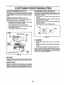
AIR FILTER (See Fig. 1S)
Your engine will not run propedy using a dirty air filter,
Clean the foam pre-cleaner after every 25 hours of operation or every season° Service paper cartridge every 100
hours of operation or every season, whichever occursfirst.
NOTE: Although multi-viscosity oils (5W30, 10W30 etco)
improve starting in cold weather, these _nulti-viscosity oils
wilt result in increased oil consumption when used above
32°F. Check your eng!ne oil level more frequently to avoid
._ossibleengine damage from running low on oi1.
Service air cleaner more often under dusty conditions.
°
Remove knob(s) and cover.
TO SERVICE PRE-CLEANER
= Slide foam pre-cleaner off cartridge.
o Wash it in liquid detergent and water.
SAE VISCOS|TY GRADES
,am m
°F
-20"
0"
_0'
32" 40"
°c
60°
B0'_
100=
,'o"
TEMPERATURE
RANGE ANTICrP,_,TED BEFORE NEXT OIL CHANGE
FIG. 13
Change the oil after the first two hours of operation and
every 25 hours thereafter or at least once a year if the
tractor is not used for 25 hours in one year.
Check the crankcase oil level before starting the engine
and after each eight (8) hours of operation. Tighten oil fill
cap/dipstick securely each time you check the oil level.
TO CHANGE ENGINE OIL (See Figs. 13 and 14)
Determine temperature range expected before oil change.
All oil must meet API service classification SF or SG,
.
Be sure tractor is on level surface.
•
•
Oil will drain more freely when warm.
Catch oil in a suitable container.
°
Remove oil fill capldipstick. Be careful not to allow dirt
to enter the engine when changing oil.
°
Remove drain plug.
°
After oil has drained completely, replace oil drain plug
and tighten securely.
°
Refill engine with oil through oil fill dipstick tube. Pour
slowly. Do not overfill. For approximate capacity see
PRODUCT SPECIFICATIONS on page 3 of this
manual,
o
=
Squeeze it dry in a clean cloth,,
:
Saturate it in engine oil. Wrap it in clean, absorbent
cloth and squeeze to remove excess oil.
°
If very dirtyor damaged, replace pre_cleaner.
=
°
TO
°
°
Reinstall pre-,cleaner over cartridge.
Reinstall cover and secure with knob(s).
SERVICE CARTRIDGE
Remove cartridge nut.
Carefully remove cartridge to prevent debris from
entering carburetor° Clean base carefully to prevent
debris from entering carburetor.
°
Ctean cartridgebytapping gentl_,on flat surface. If very
dirty or damaged, replace cartndge.
°
Reinstall cartridge, nut, precleaner, cover and secure
with knob(s)_
IMPORTANT:
PETROLEUM SOLVENTS, SUCt;I AS
KEROSENE, ARE NOT TO BE USED TO CLEAN THE
CARTRIDGE° THEY MAY CAUSE DETERIORATION OF
THE CARTRIDGE. DO NOT OIL CARTRIDGE° DO NOT
USE PRESSURIZED
AIR TO CLEAN OR DRY
CARTRIDGE.
KNOB
CARTRIDGE
NUT
COVER"
Use gauge on oil fill capldipstickfor checking level. Be
sure dipstick cap is tightened securely for accurate
reading° Keep oil at "FULL" line on dipstick°
CARTRIDGE
19
FIG. 15
CLEAN AiR SCREEN
(See Fig. 16)
IN-LINE FUEL FILTER
Air screen must be kept free of dirt and chaff to, prevent
engine damage from overheating, Clean with a wire brush
or compressed air to remove dirt and stubborn dried gum
fibers.
ENGINE COOLING
FINS (See Fig. 16)
Remove any dust, dirt or oil from engine cooling fins to
prevent engine damage from overheating.
= Remove screws from blower housing and iift housing
and dipstick tube assembly off engine.
o Cover oil fill opening to prevent entry of dirt.
o
°
(See Fig. 17)
The fuel filtershould be replaced once each season. Iffuel
filter becomes clogged, obstructingfuel flow to carburetor,
replacement is required.
°
With engine cool, remove filter and plug fuel line
sections.
°
Place new fuel filter in position in fuel line with arrow
pointingtowards carburetor.
o
Be sure there are no fuel line leaks and clamps are
properly positioned.
o
Immediately wipe up any spilled gasoline.
Use compressed air or stiff bristlebrushto thoroughly
clean engine cooling _ins.
To reassemble, reverse above procedure.
CLAMP _.
•
_.. CLAMP
FUEL
_
FILTER r.
SCREWS
BLOWER HOUSING
//
SCREWS
RG. 17
CLEANING
AIR SCREEN
OIL RLL
TUBE
ASSEMBLY
FIG. 16
MUFFLER
Inspect and replace corroded mufflerand spark arrester (if
equipped) as it could create a fire hazard 'and/or damage.
SPARK PLUGS
Clean engine, battery, seat, finish, etcoof all foreign
matter.
°
Keep finishedsurfaces and wheels free of all gasoline,
oil, etc.
°
Protect painted surfaces with automot_e type wax.
We do not recommend using a garden hose to clean your
tractor unless the electrical system, muffler, air filter and
carburetor are coveredto keepwater out. Water in engine
can result in a shortened engine I_fe.
SPARK
PLUG
ENGINE COOLING RNS
°
,
Replace spark plugs at the beginning of each mowing
season or after every 100 hot,re of operation, whichever
occursfirst. Spark plug type and gap settingare shown in
. =PRODUCT SPECIFICATIONS" on page 3 ofthis manual
20
SERVmCE AN
ADJUST JIENTS
CAUTION: BEFORE PERFORMING ANY SERVICE OR ADJUSTMENTS:
,
=
°
=
=
Depress clutcWbrake pedal fully and set parking brake.
Place gearshift lever in neutral (N) position.
Place attachment clutch in "DISENGAGED" position.
Turn ignition key "OFF" and remove key.
Make sure the blades and all moving parts have completely stopped.
Disconnect spark plug wire from spark plug and place wire where it cannot come in contact with
plug.
TO REMOVE MOWER (See Fig. 18)
CLUTCH LEVER
Mower wil!be easier to remove from the rightside of tractor.
o
o
Place attachment clutch in "DISENGAGED" position_
Move attachment liftlever forward to lowermower to its
lowest position,
°
Roll belt off engine pulley_
=
D,isconnect clutch rod from clutch lever by removing
retainer spring,
°
Disconnect anti-sway bar from chassis bracket by
removing retainer spring,
o
Disconnect suspension arms from rear deck brackets
by removing retainer springs.
°
Disconnect front linksfrom deck by removing retainer
springs.
=
Raise lift lever to raise suspension arms_ Slide mower
out from under tractor,
RETAINER
SUSPENSION
ARMS
SPRINGS
SIDES
IMPORTANT:
IF AN ATTACHMENT OTHER THAN THE
MOWER IS TO BE MOUNTED TO THE TRACTOR,
REMOVE THE FRONT LINKS. '
RETAINER
SPRING
ANTI-SWAY BAR
TO INSTALL MOWER (See Fig. 18)
°
Raise attachment lift lever to its highest position,
°
Slide mower under tractorwith dischargeguard to right
side of tractor°
=
°
Lower lift lever to its lowest position.
Install mower in reverse order of removal instructions,
ENGINE
PULLEY
RETAINER
SPRINGS
(BOTH SIDES)
FIG. 18
21
SERVnCE A
ADJ
................
TO LEVEL MOWER
HOUSING
At the midpointofboth sides ofmower, measure height
from bottomedge of mower to ground° Distance =A"on
both sides of mower should be the same or within 1/4°
of each other°
°
Check adjustment on right side of tractor. Measure dis.
tance"D" directly in front and behind the mandrel at bottom
edge of mowe'r housing as shown.
° Before making any necessary adjustments, checkthat
both front links are equa! in length. Both links should
be approximately 10-3/8.
,
If links are not equal in length, adjust one link to same
length as other link.
° To lower front of mower loosen nut "E" on both front
links an equal number of turns.
° When distance "D" is 1/4" to 3/4" lower at front than
rear, tighte n nuts "F" against trur_nion on both front
links.
if adjustment is necessary, make adjustment on one
side of mower onlyo "
To raise one side Of mower, tighten lift linkadjustment
nut on that side.
To lower one side of mower, loosen lift linkadjustment
nut on that side.
NOTE: Each fullt_m of adjustment nut willchange mower
height about 1/8".
o Recheck measurements after adjusting.
BOTTOM EDGE
OF MOWER TO
GROUND
..
To obtain the best cutting results, the mower housing
shouldbe adjustedso that the front is approximately 1/4"to
3/4=lower than the rear when the mower is in its highest
position.
SIDE-TO-SIDE ADJUSTMENT (See Figs_19 and 20)
= Raise mower to its highest position.
=
.,
FRONT-TO-BACK ADJUSTMENT (See Figs. 21 and 22)
IMPORTANT: DECK MUST BE LEVEL SIDE-TO-SIDE. IF
THE FOLLOWING FRONT-TO-BACK ADJUSTMENT IS
NECESSARY, BE SURETO ADJUST BOTH FRONT LINKS
EQUALLY SO MOWER WiLL STAY LEVEL SIDE=TO_
SIDE.
..,
Adjust the mower while tractor is parked on tevelgroundor
driveway. Make sure tires are properly inflated (See
"PRODUCT SPECIFICATIONS onpage 3 ofthis manual).
Iftires are over or underinflated, you will notproperly adjust
your mower.
o
:.:
•
BOTTOM EDGE
OF MOWER TO
GROUND
•
,
To raise front of mower,.ioosennut"F" from thJnnion on
both front links. Tighten nut "E" on both front links an
equal number of turns.
When distance "D" is 1/4" tO 3/4" lower at front than
rear,tighten nut"F",againsttrunnionon both front links.
Recheck side-to_side adjustment.
MANDREL
GROUND UNE
FIG. 19
SUSPENSION
ARM
RG. 21
BOTH FRONT UNKS MUST BE EQUAL IN LENGTH
LIFt UNK
ADJUSTMENT
NUT
FIG. 20
NUT =E"
FRONT LINKS
22
TRUNNION
FIG. 22
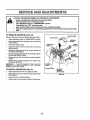
RVltCE AND ADJ
TO REPLACE
(See Fig. 23)
MOWER
BLADE DRIVE BELT
ENTS
WITH PARKING BRAKE "ENGAGED"
The mower blade drive belt may be replaced withouttools,
Park the tractor on level surface. Engage parking brake.
BELT REMOVAL =
Remove mower from tractor (See %0
MOWER" in this section of this manual).
REMOVE
°
Work belt off both mandrel pulleys and idler pulleys_
°
Pull belt away from mower.
NUT "A_
JAM NUT
BELT INSTALLATION ,
Install new belt in reverse order of removal.
D
,
Make sure belt is in all pulley grooves and inside all belt
guides.
install mower in reverse order of removal instructions.
OPERATING
ARM
FIG. 24
MANDREL
PULLEY
IDLER
PULLEYS
TO REPLACE
(See Fig. 25)
MOTION
DRIVE BELT
Park the tractor on level surface. Engage parking brake°
For assistance, there is a belt installation guide decal on
bottom side of left footrest°
•
Remove mower (See "TO REMOVE MOWER" in this
section of this manual.)
o
Remove upper belt keeper.
,
,
Remove belt from stationary idler and clutching idler.
Pull belt slack toward rear of tractor. Remove belt
upwards from transaxte pulley by deflecting belt keepers.
•
MANDREL
PULLEY
o Install new belt by reversing above procedure,
IMPORTANT: MAKE SURE UPPER BELT KEEPER IS
POSITIONED PROPERLY BETWEEN LOCATOR TABS°
RG. 23
TO ADJUST
BRAKE (See Fig. 24)
ENGINE-_,-4_..=_
Your tractor is equipped with an adjustable brake system
which is mounted on the right side of the transaxle.
Measure distance between brake operating arm and
nut =A" on brake rod,
.
ifdistance is otherthan 1=1/2",loosen jam nut and turn
nut "A" until distance becomes 1-1/2"_ Retightenjam
nut against nut "A".
•
Roadtest tractorfor proper stoppingdistance as stated
above. Readjust if necessary. If stoppingdistance is
still greater than six (6) feet in highest gear, further
maintenance is necessary. Contact your nearest authorized service center/department.
_
CLUTCHmNG-.-.4_--"_',_'-_--_.
_'-
li tractor requires more than six (6) feet stoppingdistance
at highspeed in highest gear, then brake must be adjusted°
•
Depress clutch!brakepedaland engage parking brake.
.
Pull belt toward front of tractor and remove downwards
from around engine pulley.
II
STATIONARY""-Ii
...j,_o)) |
_
|
I I
il
II TABS
I_ UPPERBELT
!1 KEEPER
II
!i II ll
TRANSAXLE.,_ II
J-.FL-.,,
FIG. 25
23
Ii
ENTS
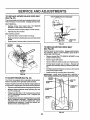
TO ADJUST
STEERING
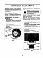
TO START ENGINE WITH A WEAK BATTERY
See Fig. 27)
WHEEL ALIGNMENT
if steering wheel crossbars are not horizontal (left to right)
when wheels are positionedstraightforward, remove steeringwheel and reassemble per instructionsinthe Assembly
section of this manual.
CAUTION: Lead-acid batteries generateexplosivegases. Keep sparks, flama
and smoking materials away from batteries. Always wear eye protection
when around batteries.
FRONT WHEEL TOE-IN/CAMBER
The front wheel toe-in and camber are not adjustable on
your tractor. If damage has occurred to affect the front
wheel toe-in or camber, contact your nearest authorized
service center/departmento
if your battery is too weak to start the engine, it should be
recharged°
If "jumper cables" are dsed for emergency
starting, follow this procedure:
IMPORTANT: YOUR TRACTOR IS EQUIPPED WITH A 12
VOLT NEGATIVE GROUNDED
SYSTEM.
THE OTHER
VEHICLE
MUST ALSO BE A 12 VOLT NEGATIVE
GROUNDED SYSTEM.
DO NOT USE YOUR TRACTOR
BATTERY TO START OTHER VEHICLES.
TO REMOVE WHEEL FOR REPAIRS
(See Fig. 26)
o
•
Block up axle securely.
Remove axle cover, retainingring and washersto allow
wheel removal (rear wheel contains a square key- Do
not lose).
•
Repair tire and reassemble.
,
On rear wheels only: align grooves in rear wheel hub
and axle. Insert square key.
°
Replace washers and snap retaining ring securely in
axle groove.
Replace axle cover.
°
TO ATTACH JUMPER CABLES °
Connect each end of the RED cable to the POSITIVE
(+) terminal of each battery, taking care not to short
against chassis.
°
Connect one end of the BLACK cable to the NEGATIVE (-) terminal of fully charged battery.
°
Connect the other er_d of the BLACK cable to good
CHASSIS GROUND, away from fuel tank and battery.
TO REMOVE CABLES, REVERSE ORDER °
BLACK cable first from chassis and then from the fully
charged battery.
= REDcable last from both batteries.
WASHERS
RETAINING
RING
NEGATIVE TERMINAL
POSITIVE TERMINAL
!
AXLE COVER
'_SQUARE
KEY
(REAR WHEEL ONLY)
FIG. 26
CABLES
CHARGED
BATTERY
POSITIVE TERMINAL
NEGATIVE TERMINAL
RG, 27
24
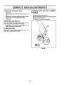
TO REPLACE HEADLIGHT BULB
o
o
=
o
TO REMOVE HOOD AND GRULL ASSEMBLY
(See Fig. 28)
Raise hood.
Pull bulb holder out of the hole in the backside of the
grill.
Replace bulb in holder and push bulb holder securely
back into the hole in the backside of the grill.
Close hood.
INTERLOCKS
o
Raise hood_
°
=
Unsnap headlight wire connector.
Standinfrentoftractor. Grasphoodatsides, tilttoward
engine and lift off of tractor°
To replace, reverse above procedures.
°
AND RELAYS
Loose or damaged wiring may cause your tractor to run
poorly, stop running, or prevent itfrom starting.
o
Check wiring° See electrical wiring diagram in the
Repair Parts section of this manual.
TO REPLACE
HOOD
FUSE
Replace with 30 amp automotive-type ptug-infuse. The
fuse holder is located behind the dash.
H£ADUGHT
WIRE
CONNECTOR
FIG. 2B
25
IENGBNE
:
:
",'",.
]IIIL_
I_
Ill
:
:5
..............
II
I
ll_L
'
'ill I'
: .....
,,,,
....
,,
,
FINAL SETTING -
TO ADJUST THROTTLE
(See Fig. 29)
CONTROL
CABLE
The throttle control has been preset at the factory and
adjustmentshouldnot be necessary. Check adjustment as
described below before loosening cable, if adjustment is
necessary, proceed as follows:
o
II
ADJUSTMENTS
.......
o
:
..................
l
II
lllll
SERVICE AN
\
Start engine and allow to warm for five minutes. Make
final adjustments with engine running and shift/motion
control lever in neutral (N) position.
°
Move thro_le control lever to slow (,_!) position, With
ringer, ro[azeand hold throttle lever.against idle speed
screw. Turn idle speed screw to attain 1750 RPM.
°
While still holding throttle lever against idle speed
screw, tum idle mixture valve in (clockwise) untlf en,,
gine begins to die and then tum out (counterclockwise)
until engine runs rough. Turn valve to a point midway
.between those two positions. Release throttle lever°
ACCELERATION TEST -
With engine not running, move throttle control lever
from stow (,_) to choke (N) position. Slowly move
lever from choke (N) to fa_;t(,_) pbsition.
Check that holes"A" in govemorcontrollever and hole
in governor plate line-up. If holes "A" are not aligned,
loosenclamp screw and movethrottlecable until holes
are aligned. Tighten clamp screw securely.
GOVERNOR
CONTROL LEVER
•
°
GOVERNOR
Move throttle control lever from slow (-_!) to fast (,_)
position. If engine hesitates or dies, turn idle mixture
valve out (counterclockwise)118turn. Repeat test and
continue to adjust, if necessary, until engine accelerates smoothly.
CONTROL PLATE
High speed stop is factory adjusted. Do not adjust damage may result.
IMPORTANT:
NEVER TAMPER WITH THE ENGINE
GOVERNOR, WHICH IS FACTORY SET FOR PROPER
ENGINE SPEED_ OVERSPEEDING THE ENGINE ABOVE
THE FACTORY HIGH SPEED SETTING CAN BE
DANGEROUS. IF YOU THINK THE ENGINE-GOVERNED
HIGH SPEED NEEDS ADJUSTING, CONTACT YOUR
NEAREST
AUTHORIZED
SERVICE
CENTER/
DEPARTMENT, WHICH HAS PROPER EQUIPMENT AND
EXPERIENCE
TO
MAKE
ANY
NECESSARY
ADJUSTMENTS_
HOLES "A=
CLAMP
SCREW
THROTTLE
LEVER
IDLE SPEED
SCREW
THROTTI.E
CABLE
FIG. 29
TO ADJUST
CARBURETOR
(See Fig. 30)
The carburetor has been preset at the factory and adjustment should not be necessary. However, minor adjustment may be requiredto compensatefor differences infuel,
temperature, altitude or load. If the carburetor does need
adjustment, proceed as follows:
In general, turning idle mixture valve in (clockwise)decreasesthe supplyoffuel tothe engine givinga leaner fuel/
air mixture. Tuming the idle mixture valve out (counterclockwise) increasesthe supplyof fuel to the engine giving
a richer fuel/air mixbJre.
IMPORTANT: DAMAGE TO THE NEEDLE VALVE AND
THE SEAT IN CARBURETOR MAY RESULT 1FSCREW IS
TURNED IN TOO TIGHT.
IDLE MIXTURE
VALVE
PRELIMINARY SETTING o
Aircleaner assernblymust be assembled to the carbu.
retor when making carburetor adjustments.
°
Be sure the throttle controlcable is adjusted properly
(see above).
°
With engine off turn idle mixture valve in (clockwise)
closing itfinger tight and then turn out (counterclockwise) 1 full turn.
FIG. 30
26
STORAGE
ENGUNE
Immediately prepare your tractor for storage at the end of
the season or if the tractor will not be used for 30 daysor
more.
U
_
_ JL
_
M_
_.
FUEL SYSTEM
IMPORTANT:
IT IS IMPORTANT TO PREVENT GUM
DEPOSITS
FROM FORMING
IN ESSENTIAL
FUEL
SYSTEM PARTS SUCH AS CARBURETOR, FUEL FILTER,
FUEL HOSE, OR TANK DURING STORAGE.
ALSO,
EXPERIENCE
INDICATES THAT ALCOHOL BLENDED
FUELS (CALLED GASOHOL OR USING ETHANOL OR
METHANOL) CAN ATTRACT MOISTURE WHICH LEADS
TO SEPARATION AND FORMATION OF ACIDS DURING
STORAGE.
ACtDIC GAS CAN DAMAGE THE FUEL
SYSTEM OF AN ENGINE WHILE IN STORAGE.
CAUTION: Never store the tractor with
gasoline in the tank inside a building
where fumes may reach an open flame
or sparlt. Allow the engine to cool
before storing in any enclosure.
TRACTOR
Remove mower from tractor for winter storage. When
mower is to be stored for a period of time, clean it thoroughly, remove all dirt, grease, leaves, etco Store in a
clean, dry area.
-
Clean entiretractor (See"CLEANING"in the Customer
Responsibilities section of this manual).
o
inspect and replace belts, if necessary (See belt replacement instructions inthe Service and Adjustments
section of this manual).
•
Lubricate as shown in the Customer Responsibilities
section of this manual.
°
Be sure that all nuts, bolts and screws are secureiy
fastened, inspect moving parts for damage, breakage
and wear, Replace if necessary.
Touch up all n_sted or chipped paint surfaces; sand
lightlybefore painting.
=
Fully charge the battery for storage.
After a period of time in storage, battery may require
recharging.
°
To help prevent corrosion and power leakage during
long periods of storage, battery cables should be
disconnected and battery cleaned thoroughly (see TO
CLEAN BATTERY AND TERMINALS in the Customer Responsibilities section of this manual).
•
°
°
Drain the fuel tank.
°
Start the engine and let it run until the fuel lines and
carburetor are empty.
•
Never use engine or carburetor cleaner products in the
fue! tank or permanent damage may occur.
Use fresh fuel next season.
°
NOTE: Fuel stabilizer is an acceptable alternative In
minimizing the formation of fuel gum deppsits during storage. Add stabilizer to gasoline in fuel tank or storage
container. Always follow the mix ratio found on stabilizer
container. Run engine at least 10 minutes afteF adding
stabilizer to allow the stabilizer to reach the carburetor. Do
not drain the gas tank and carburetor if using fuel stabilizer_
ENGINE OIL
Drain oil (with engine warm) and replace with clean engine
oil. (See "ENGINE" in the Customer Responsibilities
section of this manual).
BATTERY
o
o
°
CYLINDERS
After cleaning, leave cables disconnected and place
cables where they cannot come in contact with battery
terminals.
°
°
Remove spark plug(s).
Pour one ounce of oil through spark plug hole(s) into
cylinder(s)o
°
Turn ignitionkey to"START" positionfor a few seconds
to distribute oil.
•
Replace with new spark plug(s).
OTHER
Be sure battery drain tube is securely attached.
If battery is removed from tractor for storage, do not
store battery directly on concrete or damp surfaces.
°
°
Do not store gasoline from one season to another.
Replace your gasoline can if your can starts to rust.
Rust and/or dirt in your gasoline will cause problems.
= If possible, store your tractor indoors and cover it to
give protection from dust and dirt.
° Cover yourtractor with a suitable protective cover that
does not retain moisture. Do not use plastic, Plastic
cannot breathe which allowscondensationto form and
will cause your tractor to rust.
IMPORTANT: NEVER COVER TRACTOR WHILE ENGINE
AND EXHAUST AREAS ARE STILL WARM°
27
TROU
PROBLEM
: :: ::::: :
HOOTING
CAUSE
CORRECTION
,,
,,,, ,,,,j ..............
Willnot start
1.
2.,
3o
4.
5,
6o
7,
,,,,,,,,,,,,,,,,,,
,, ,,,,,
Outof fuel, ,
Enginenot'CHOKED"propedyo
Engtneflooded,
Badsparkplug,
Dirtyair filter,
Dirtyfuelfilter,
WaterIn fuel.
1,
2.
3,
4°
5,
6
7o
B,, Looseor damagedwidng.
9_ Carburetoroutof adjustmenL
lo. Eng!no cut
ota !u ent,.......
Herd to atzzrt
"L
2_
3,
4,
5+
6
7,
Dfrtyalrfitter°
Badsparkplug,
Weakor deadbattery.
Dirtyfuelfilter.
StBJeor dirtyfuel.
Looseor damagedwtdng,
Carburetoroutof adjustmenl
8,
Enginevalvesoutof adjustment.
:
Engine wltl not turn over
POINTS
' "1"1',,I, I
Rlif,Jel tank.
See =TOSTART ENGINE"tn Operationsectlom
Waitsevere]minutes beforeattempting to start
Replacesparkplug.
Clean/replaceair fitter.
Replacefuelfilter°
Dr'-_nfuel tankand carburetor,refilltankwith,fresh,
gesotineand replacefuelfilter.
8. Check_ widng,
9. See=ToAdjustCarburetor"in ServiceAdjustman_
_n_on_*
10. Contact an authorizedservicecenter/department.
1_
2.
3,
4,
5,
6,,
7.
......
8,
Clean/replaceair fi]ter_
Replacesparkplug.
Rechargeorreplacebattery,,
Replacefuel fiffer.
Drainf,Jaitankand refillwithfreshgasoline°
Checkai!wtdng.
See"To AdjustCarburetor"In ServiceAdjustments
section.
Contactan authorizedservicecanter/departmenL
i,
1_
2_
3,
4,,
5,
6,.
7,
8,,
9,
Clutch/brakepedalnotdepressed°
Attachmentclutchisengaged.
Weakor deadbattery°
Blownfuse°
Corrodedbatteryterminals.
Looseor damagedwidng,,
Faultyignitionswitch°
Faultysolenoidorstartan
Faultyoperatorpresenceswfteh(es).
1,
2.
3.
4o
5,
6.
7.
8°
9.
Depressclutch/brakepedaL.
Disengageattachmentclutch,
Rechargeor replacebattery,,
Replacefuse,
Cleanbakeryterminals.
Checkall wiring,
Check!replaceignitionswitch,
Check/replacesolenoidor starter.
Contactan authorizedservice center/department,
Engine clicks but will not
start
1,,
2_
3,
4,
Weakor dead battery,
Corrodedbatten]terminals
Looseordamagedwidng
Faultysolenoidor starter.
1o
2_
3.
4.
Rechargeor replace battery.,
Cleanbatterytarmlna!so
Checkagwidngo
Check/replacesolenoidor starter.
Loss of power
1,
2`.
3_
4_
5.
6.
7.
8.
g.
CL_ng too much grass/too fasL
Throttle in "CHOKE" position.
Build-up of grass, leaves and trash under mower.
Ditty air filter.
Low oil level/dirty off.
Faulty spark plug,
Dirty fue! filters
Stale or dtdy fuel.
Water in fuel,,
1.
2,
3o
4.
5o
6,
7_.
8,
9.
Sat in "Higher Cut"position/reduce
speed,
Adjustthro_e control
Cleanundersideof mowerhousing,
ClearJreplaceair filter.
Checkoillevel/changeoH,
Cleanand regapor change,sparkplug_
Replacefuelfilter.,
Drainfueltankandrefillwith freshgasoline.
Drainfuel.tank andcarburetor,refilltank withfresh
gasolineandreplacefuel filter,
Connectand tightensparkplugwire,
Cleanengine air screen/fins,,
Clean/replacemuffier,I
Checkalt widng.
See =ToAdjustCarburetor"In ServiceAdjustments
section.
Contact an authorizedservicecenter/departmenL
L
10,.
11.
12.
t3.
14,
Spark plug wire loose.
Dirty engine air screen/fins.
Dirty/clogged muffler.
Loose or damaged wtdng.
Carburetor out of adJustmanL
10°
11,
12o
13,
14,
15o Enginevalvesoutofadjustment,
iii
Excessive vibration
IIM'
15o
ii ,,,11,
I"11 H_L"_
1. Worn, bent or loose blade.
2o Bent blade mandrel.
1.
2,
3_
3,_ Loose/damaged part(s)o
28
............
I "1
lUI'_II'III'"
I
Replace blade. Tighten blade boll
Replace blade mandrel.
Tighten loose part(s)o Replace damaged parts.
TFIOUBLESHOOTING
CORRECTION
CAUSE
PROBLEM
Engine continues to run
when operator leaves seat
with attachment clutch
POINTS
!,,
1_ Faulty operator*safety presence control system,
Check wiring, switches and conneclJonso If not
corrected, contact an authorized service center/
department.,
engaged
r=l"l"=
........
Poorcut-uneven
......
r
'
'l'l _l']_l']]U'H
....
1.
2,,
3o
4.
Worn, bent or loose blade.
Mower deck not level.,
Buildup of grass, leaves, and trash under mower°
Bent blade mandrel,.
5,
Clogged mower deck vent holes from buildup of
grass, leaves, and trash around mandrels_
1,,
2r,
3o
4,,
Obstruction in clutch mechanism.
Worn/damaged mower drive belt,.
Frozen idler gulley_
Frozen blade mandrel..
1_ Replace b!adeo Tighten blade boll
2, Level mower deck,
3, Clean underside of mower housing
4. Replace blade mandrel,,
5, Clean around mandrels to open vent holaso
.,rhrr,
Mower blades will not
rotate
...................
i
i ,,i,,i
Poor grass discharge
1.
2,
3,
4o
5_
6o
7
8,
i
, ii,,,i,,,i,,
......
1,
2,
3,
4,
i,
Io
2.
3,
4_
5
6,,
7o
, 8.
9,
10_
11,,
Engine speed too slow_
Travel speed too fast,
Wet grass,
Mower deck not level.
Low/uneven tir_ a_rpressure,
Worn, bent or loose b!sde_
Buildup of grass, leaves and trash under mower,,
Mower drive belt worn
9_ Blades improperly installed,,
10, improper blades used.
11o Clogged mower deck vent holes from buildup of
grass, leaves, and trash around mandrels.,
_,,..................
i,,,,,ii
Headlight(s) not working
(if so equipped)
,,11'IH'"
Battery wt!l not charge
Engine "backfires"
when turning engine
"OFF"
,ir,,i
1.,
2.
3.
4o
5,,
i
=
i,r_l
i illll,,,
] _11_13
Turn switch "ON"_
2,
3o
4.
5,
Replace bulb[s).
Check/replace fight switch_
Check wiring and connections°
Replace fuse.
ii,,
I_
2,,
3
4,,
Engine throttle cootro] not set at "SLOV'#'
position for 30 seconds before stopping engtna,.
ii
1.
, I ' ]_][ _[_
Bad batteryceil(s),,
Poor cableconnections_
Faultyregulator(ifsoaquipped)_
Faulty,'dtamatoro
..... i,l,ll,l,,l
PlacE)throttle control in "FAST" position_
Shift to slower speed.
Nlow grass to dry before mowing,
Level mower deck,
Check tires for proper air pressure.
Replace/sharpen blade_ Tighten blade boll
Clean underside of mower houslng.
Replace mower drive belt.
Reinstall blades sharp edge down°
Replace with blades listed in thts manual
Clean around mandrels to open vent holeso
i
Switch Is"OFF",
Bulb(s) bumed ouL
Faulty light switch.
Loose or damaged wifingo
Blown fuse.
_,111,,i,,
1.,
2,.
3°
4,
i,,]H
Remove obstruction,,
Replace mower drive belt,
Replace idler pulley,,
Replace blade mandrel.
illlll
Ill Ill
Ill
29
,, ,i,i ,i.................
] ,,,
i ,,
Replace battery.
Check/clean sti connections,
Replace regulator,
Replace alternator,
Move throttle control tO "SLOW" position and allow
to idle for 30 seconds before stopping englne.
,,,ll _1
i
i
ii,,,,i,ii
ii,,,i
,, i
30
TRACTOR-...
MODEL
NUMBER
917.258510
SCHEMATIC
RED
BLACK
BATTERY
RED
A_
1
RE.__O
MMETE R ........
FUSE 30 AMP,.
WH_,,
I ............
{_
I
•
I
%J"
BLACK ....
I
' ©'
'-J-J%
STARTER
_
'_
J
vl
,.
I
]
SOLENOID
: (%-j_
t ........
I|!
I
J
CLUTCH/ BRAKE
(PEDAL UP)
WHITE
SEAT SWITCH
(NOT OCCUPIED
I IGNIT!ON SWITCH
WHITE
I........
'
i
!
1
|1....
-
I
I
I
BLACK
J
ArT'
ENT OFF)
LUTCH
(CLUTCH
"l I
GROUNDING
CONNECTOR
O
BLACK
UNIT
IGNITION
(_
CHARGING SY_FF.=M OtTrPUT
3 AMP DO @ 3600 RPM
28 VOLTS AC MIN. @ 3600 RPM
(CHARGtNG SYSTEM DISCONNECTED)
ua_N_sYSTEM z _
ou'_uT
,..._DIODE
5 AMP AC O_
NOTE
YOUR TRACTOR IS
EQUIPPED WiTH A SPECIAL
ALTERNATOR SYSTEM.
THE LIGHTS ARE NOT
CONNECTED
TOTHE
.....
1_
I_
I_
I =.....
__
PLUG __
SPARK
___
"_\
--
t..--___.T._Z_
T,
_ALTERNATOR I i
_
.
.
_
.........
"
t '.
J
" t4 VOLTS AC MtN @ 3600 RPM (UGi.rlrS
OFF)
HEADLIGHTS
,
"_I_L_
;_-______; _ T _-J
T-
BATTERY, BUT HAVE THEIR
I_EAD_.IGI¥1:
I _
t
OWN ELECTRICAL SOURCE°
SWIT_3-Pt"
'
_
_-J
BECAUSE OF THIS, THE
(OFF)
BRIGHTNESS OF THE LIGHTS
IGNITION SWITCH
WILL CHANGE WITH ENGINE
PosrnoN
ClRCUrr
SPEED. AT IDLE THE LIGHTS
WILL DIM. AS THE ENGINE IS
WIRING INSULATED CLIPS
/'_
...............
OFF
M+ G
SPEEDED UP, THE LIGHTS
ON
B+L
NOTE:
IF
WIRING
INSULATED
i
WILL BECOME THEIR BRIGHTEST.
START
B+ S + L
CLIPS WERE REMOVED FOR
SERVICING OF UNIT, THEY
SHOULD BE REPLACED TO
NON-REMOVABLE
_
REMOVABLE
PROPERLY SECURE YOUR WIRING.
CONNECTIONS
CONNECTIONS
31
REPAUR PARTS
TRACTOR =- MODEL NUMBER 917.258510
ELECTRICAL
21
/
26
t
t
I
I
I
)
16
T
.
I
/
!
/
/
/
1
\
1
\
i/
\
I
1
/
s./
1
I
I
I
l
I
|
!
|
32
/
/
REPAIR PARTS
TRACTOR
- - MODEL
NUMBER
917.258510
ELECTRICAL
KEY
NO.
1
2
3
4
6
7
6
9
15
16
19
20
21
22
24
25
26
28
29
30
31
32
33
40
41
42
43
44
45
52
70
PART
NO.
146139
74760412
STD551025
STD551125
STD541025
109238X
156417
109596X
147668'
153664
STD551125
73350400
t36850
4152J
4799J
146147
108824X
4207J
121305X
140301
124211X
141226
109310X
156442
71110408
131563
145673
73640400
121433X
141940
140422
DESCRIPTION
Battery 12 Volt 25 AMP
Bolt Hex Hd 1t4-20unc X 314
Washer 9/32 X 5/8 X 16 Ga
Washer Lock Hvy Helical 1/4
Nut Fin Hex 114-20 Unc
Tube Plastic 12"
Case Battery
Clamp Hose Olive
Fastner Snap-In
Switch Interlock Push-In
Washer Lock 114
Nut Jam Hex 1/4-20 Unc
Harness Socket Light W/4152J
Bulb Light #1156
,
Cable Battery 6ga 11 red
Cable Battery 6 Ga W/16 Wir red
Fuse 30 AMP Auto Green'
Cable Ground 6ga 12" black
Switch Plunger Nc Gray
Switch Ign 4 pos
Nut Ignition
Cover Sw Ignition .
Key Ign Molded Craftsman, Delta
Harness Man C1Am Hm 97
Bolt BIk Hex 114-20unc x 1/2
Cover Terminal Red
Solenoid
Nut Keps Btk Hex 1/4-20 Unc
Ammeter Rectangular 6 AMP
Protection Wire Loop
HamessEngine, Dual 14 OHV
NOTE: All component dimensions
1 inch = 25_4 mm
33
given in U.S. inches
REPAltR PARTS
TRACTOR ,-,, MODEL NUMBER 917.258510
CHASSIS AND ENCLOSURES
3O
\
17
21
22
•
_1o0
29
I
28
°
t
14...,,,.
4--,..
33
10
26
3
14
34
REPAIR PARTS
TRACTORCHASSIS
= MODEL
NUMBER
917.258510
AND ENCLOSURES
KEY
NO.
1
2
3
4
5
6
7
8
9
10
11
13
14
15
t6
17
18
19
21
22
24
25
26
27
28
29
30
31
33
34
35
38
39
100
140
--
PART
NO.
155051
140356
17490612
STD551025
155272
155924)(012
126842X
155138
156275)(010
STD533710
146956
146961X012
1'7490608
74180512
STD541431
154988)(574
126938X
17521312
122933X
124479X
STD523710
19131312
STD541437
17030814
140137
124029X
109872X574
136619
145244X574
145243)(574
STD533707
139686
139887
!05037X
150556
5479J
DESCRIPTION
Chassis Wtdmt
Drawbar Stretch
Screw Thdrol 3f8-16 x 3/4 Ty-tt
Washer 13132X 3!4 X 16 Ga
Bumper Dash Hood
Saddle Stkscr Fit Lt 6sp Peerless
Shield Ht. Hood Kohl/Dia Engine
Clip Retainer Slide On
Dash Slkscr 1-pc
Bolt Rdhd Sqnk 3/8-16unc X 1
Panel Dash LH
Panel Stkscr Dash RH
Screw Thdrol 3/8-16 x 112Ty-tt
Screw Mach TRHD 5/16-18 unc x 3/4
Nut Keps 5116-18 Unc
Hood Asm Pnt Slope Weld Ms_574
Bumper Hood
Screw Sltd Hex Hd W/P1 Washer
Rivet Ratchet Nylon
Washer Nylon BIk 28 x "Z5x 19
Bolt Fin Hex 3/8_16 unc x I Gr_5
Washer 13/32 X 13116x 12 Ga
Nut Hex LockW/Ins. 3/8-16 Unc
Screw Spidedoc Hex Hd #8 x 7/8
Grille Grey
Lens Headlight Bar Clear
Fender Pnt LT W/o Shift
Bracket Fender Rept 109873x
Footrest Pnt Lh
Footrest Pnt Rh
Bolt Rdhd Sht Sqnk 318-16 x 3/4
Bracket Asm Pvt LH MWR Rear
Bracket Asm Pvt RH MWR Rear
Strip Foam 18"
Bracket Chassis Front 7 Ga.
Plug Button BIk 359 Dia Choke
NOTE: All component dimensions given in U.S. inche
1 inch = 25.4 mm
35
REPAnR PARTS
TRACTOR
- - MODEL
NUMBER
9"07.258510
DRIVE
121
52
1
I
1
1
_... 48
18
118
26
51
6
1
32
35
77
i
i
37
36
I
34
53
i
22
-i
26
36
26
27
REPAIR PARTS
TRACTOR
- - MODEL
NUMBER
917.258510
DRIVE
KEY
riO.
2
3
4
5
6
7
8
10
11
t2
13
14
15
18
19
21
22
24
25
26
27
28
29
30
31
32
34
35
36
37
38
39
PART
NO.
146682
t23666X
12000028
121520X
17490512
130802
131679
STD561210
105701X
19151216
745504'12
STD551125
7,4490544
STD523710
STD541437
106933X
130804
STD541237
106888X
STD551037
STD561210
145204
124236X
130807
127275X
STD523'107
155071
'120t 83X
STD551 O62
1572H
123674X
STD523727
KEY
NO.
DESCRIPTION
Transaxle (See Breakdown)
Peerless Model P930-055A
Spring Return Brake Tla Zinc
Pulley Transaxle 18/20" tires
Ring Retainer # 5100-62
Strap Torque 30 Degrees
Screw Thdrol 5/16-18 X 3/4 TYT
Bracket Saddle Shift Tia
Rod Shf Sdt LYf'_rT Str Blk Zinc
Pin Cotter 1/8 X 1 Cad
Washer Plate Shf 388 Sq Hole
Washer 15/32 X 314 X 16ga
Bolt 114-28unf Gr8 W/Patch
Washer Lock Hvy Helical 114
Bolt Hex FLGHD5!16-18Gr,5
Bolt Fin Hex
Nut Lock Hex W/Ins, 3/8-16 Unc
Knob Rd 1/2-13 Plstc Thds Bik
Rod Brake BIk Zinc 26 840
Nut Hex Jam 3/8-16 Unc
Spring Rod Brake 2 00 Zinc
Washer 13132 X 13/t6 X 16 Ga
Pin Cotter 1/8 X 3/4 Cad
Rod Brake Parking Lt/Yt
Cap Brake Parking Red
Bracket Mtg Transaxle
Keeper Belt LH LT 14 Ga
Bolt Hex Hd 5/16-18unc X 3/4
Shaft Asm Pedal Foot
Bearing Nylon Blk 629 id
Washer 21/32 X 1 X 16 Ga
Pin Roll 3/16 X 1"
Pulley Idler Flat
Bolt Fin Hex 3/8-16unc X 2-314
40
41
42
47
48
49
50
51
52
53
54
55
56
57
58
59
61
62
63
64
65
66
70
72
74
75
76
77
78
96
1t2
113
116
118
121
PART
NO.
4470J
t54777
19131312
127783
154604
123205X
STD523715
STD541374
STD54t431
105710X
2751R
105709X
STD523712
13080t
127274X
140312
17490612
8883R
140186
71170764
STD551143
154778
134683
19132012
137057
121749X
STD581075
123583X
121748X
4497H
'19091210
127285X
72110610
154774
154419
DESCRIPTION
Spacer Split 395 X 59 Bzp
Keeper Belt Idler
Washer 13132 X 13/16 X 12 Ga
Pulley Idler V Groove Plastic
Belicrank Asm Clutch
Retainer Belt Style Spring
Bolt Hex Hd 3!8-16unc X 1-1/2
Nut Crownlock 3/8-16 UNC
Nut Crown Lock 5/16-18
Link Clutch 7 66
Clip Line Fuel 13t32 Mtg Hole
Spring Return Clutch 6 75
Bolt Fin Hex 3/8-I6 _Jncx 1-114
V-Belt Gd Drive 95 25
Keeper Belt RH LT Pnt/zinc 16g
Keeper Belt Centerspan
Screw Thdr0[ 3/8-16x3/4 Ty-tt
Cover Pedal Blk Round
Pulley Eng CI Mech 38deg LT/YT
Bolt Hex 7/16-20x4 Gr 5
Washer Lock Hvy Hlcl Spr 7/16
Keeper Belt Engine
Guide Belt Mower Drive RH
Washer 13/32 X 1-1/4 X 12 Ga
Spacer Axle
Washer 25132 X 1 1/4 X 16 Ga
E-ring #5133-75
Key Square 2 0 X 1845/1865
Washer 25/32 X 1-5/8 X 16ga
Retainer Spring 1"
Washer 9/32 X 3/4 X 10 Ga
Strap Torque Lt
Bolt Rdhd Sq Neck 3/8-16 x 1,25
Spacer Bellcrank
Nyiiner Clutching Stl
NOTE: All component dimensions given in U.S, inches,
1 inch = 25°4 mm
37
REPABR PARTS
TRACTOR
STEERING
- - MODEL
NUMBER
917.258510
ASSEMBLY
+.+
L
'
+",_40
•*
i
_
L
+|
1
/
+
|
62
l
47
|
2g
29"
6B
28
30
38
REPAIR PARTS
TRACTOR
STEERING
- -, MODEL
NUMBER
917,258510
ASSEMBLY
KEY
NO.
PART
NO.
1 139766
2 154427
3 154422
4 154423
5 6266H
6 121748X
7 19272016
8 12000029
9 3366R
10 156438
11 STD551137
13 154779
15 73901000
17 156545
18 57079
19 124035X
20 126684X
21 STD551125
22 71100410
23 127501
25 154406
26 126847X
27 136874
28 19131416
29 17490612
3O STD561210
32 130465
36 155099
37 152927
38 155118
39 19133808
4O STD541537
41 104820X
42 t24417X
43 121749X
46 121232X
47 6855M
62 156593,
65 154780
66 154404
67 74781044
68 154429
DESCRIPTION
Wheel Steering Opp Sears Btk
Axle Asm Front Lt
Spindle Asm Lh
_,
Spindle Asm Rh
Washer Thrust .75 x 1.230
Washer 25132 x 1-5/8 x 16 Ga.
Washer 27t32 x 1-1/4 x 16 Ga.
RingKlip #T5304-75 '
Beating Col Strg Btk
Draglink Extended Stamped
Washer Lock Hvy Htcl Spr 3/8
Bearing Axle
Locknut Flange 5/8-11 UNC
Shaft Asm Strg 5/8 x 15.19 Lt
Washer Thrust .515 x .750 x .033
Support Shaft
Washer Shim 1/4 x 5/8 x .062
Washer Lock Hvy Helical 1/4
Screw Cap Sckt Hd Phos & Oil
Shaft Asm Pitman
Bracket Steering
Bushing Link Drag BIk LR
Gear Sector 22 Teeth
Washer 13/32 x 7/8 x 16 Ga_
Screw Thdrol 3/8-16 x 3/4 TY-TT
Pin Cotter 1/8 x 3/4 Cad
Rod Tie Wire Form t9.75 Mech
Bushing Strg_ 5/8 ID Dash
Screw
Cap Wheel Steer Opp Sears USA
Washer 13/32 x 2-3/8 x 8 Ga.
Locknut Center 3/8-24 Unf
Adaptor Wheel Strg. °640L635 ld
Boot Shaft Steering Craftsman
Washer 25/32 x 1-1/4 x 16 Ga.
Cap Spindle Fr Top Blk
Fitting!Grease
Steenng Assembly
Sppacer Axle
Bearing Arm Pittman
Bolt Fin Hex 5/8-11 UNC x 2-.3/4
Brace Axle
NOTE: All component dimensions given in UoS. inches
1 inch = 25.4 mm
39
REPAIR PARTS
TRACTOR
-- MODEL
NUMBER
917.258510
ENGINE
3
81
4
15
38
78
33
37
31
4O
23
29
\
OPTIONAL
EQUIPMENT
Spark Arrester
4O
REPAHR PARTS
TRACTOR
- - MODEL
NUMBER
917.258510
ENGINE
KEY
NO.
1
2
PART
NO.
132759
17720410
4
13
14
15
16
23
29
31
32
33
35
37
38
137352
272293
13280324
13200300
STD551237
156123
137180
109202X
123549X
123487X
17490512
137040
.......
40
44
46
62
72
78
81
124028X
17490412
190914'16
STD551131
71070512
1749062O
128861
DESCRIPTION
Control Th/ch RH BIk Pd115 10
Screw Hex Thd Cut 1/4-20x5/8 T
Engine (See Breakdown)Bdggs
Modet No 287707-0255-01
Muffler Exh LT B&S 14HP IC OHV
Gasket Eng 1 313 td Tin Plated
Nipple Pipe 3/8 Npt x 3"
Elbow Std 90 Degree 3/6-18 Npt
Washer Lock Ext Tooth 3/8
Shield Browning
Kit Spark Arrestor (Flat Scrn)
Tank Fuel Front t 25
Cap Asm Fuel W/sym Vented
Clamp Hose BIk
-Screw Thdro! 5t16-18 x 3!4 TYT
Line Fuel 20"
Plug Oil Drain (Order From Engine
Manufacturer')
Bushing Snap Nyl Bik Fuel Line
Screw Hexwsh Thdrof 114-20 x 3/4
..Washer 9/32 x 718 x 16 ga
Washer Lock Hvy Hlcl Spr 5116
Screw Hex Hd Cap 5/16-18 X 3/4
Screw Thdrol 3/8-16x1-.1/4 TYTT
Nut Flange 1/4-20 Starter Nut
NOTE: All component dimensions given in U.S, inches
1 inch = 25_4 mm
41
REPAIR PARTS
TRACTOR
- - MODEL
NUMBER
917o258510
SEAT ASSEMBLY
21
.4
J
I
I
I
t
26
I
i
23
12
KEY
NO.
PART
NO.
1
2
3
4
5
6
7
8
9
10
12
13
140122
140551
STD523710
19131610
145006
STD541437
124181X
17490616
19131614
155925
121246X
t21248X
DESCRIPTION
Seat
Bracket Pvt St
Bolt Fin Hex 3/8-16unc X 1
Washer Fiat 13/32 X 1 X t0 Ga
Clip Push-In Hinged
Locknut Hex WP_Vsh 3/8-16
Spring Seat Cprsn 2 250 Blk Zi
1
Screw
WasherThdrot
13/32 316-16
X 1 X X4 gy-tt
Pan Seat
Bracket Mounting Switch
Bushing Snap BIk Nyt 50 ld
KEY
NO.
PART
NO.
14
15
16
17
21
22
23
24
25
26
72050411
134300
121250X
123976X
153236
STD541431
74780814
19171912
127018X
STD551150
DESCRIPTION
Bolt Rdhd Sht Nk 1/4-20xl-3/8
Spacer Split 28x 96 Yel Zinc
Spring Cprsn I 27 Bik Pnt
Nut Lock 1/4 Lge Fig Gr 5 Zinc
Bolt Shld 5/16-18 Unc
Nut Lock Hex"W/Ins 5/16-16
Bolt Fin Hex 1/2-13 X 7/8 Gr5
Washer 17/32 X 1-3/16 X 12 Ga
Bolt Shoulder 5/16-18 X 62
Washer Lock Hvy Hlcl Spr I/2
NOTE: All component dimensions given in U.S. inches
1 inch = 25.4 mm
42
REPAUR PARTS
TRACTOR
DECALS
- - MODEL
NUMBER
917.258510
6
14
17
17
9
7
4
14
11
10
5
21
12
13
15
18
KEY
NO.
1
2
3
4
5
6
7
8
9
10
11
PART
NO.
156834
273504
150676
150677
150680
133644
142235
140837
128314
149516
156439
WHEELS
KEY
NO.
DESCRIPTION
Decal
Decal
Decal
Decal
Decal
Decal
Decal
Decal
Decal
Decal
Decal
12
13
14
15
17
18
19
21
------
Dash Inst Oper English
HP Engine
Hood RH Crafts SIp LT
Hood LH Crafts Slp LT
Grille Crafts
Maint Cust Sears Domesti
Side Pnt IcgoldBtk B & S
Brake Parking Saddle
Fender Craftsman White
Battery Dngr/Psn Eng Acme
Danger Fender Englspan
PART
NO.
4900J
146046
150678
136832
156858
156787
150333
131265
145245
145247
138311
156845
156846
DESCRIPTION
Decal Clutch/brake English
Decal V-Belt Dr Sch Tractor
Decal Chassis 6sp 42"
Decal V-Belt Sch
Decal Ins Hood
Decal Mower EZ3 Mulch
Decal Cap CNSMR Help Line SRS
Decal Lightbox
Pad Footrest
Fastener Pop In
Decat Handle Lft Hei_]htAdjust
Manual Owners English
Manual Owners Sl_anish
& TIRES
KEY
NO.
PART
NO.
DESCRIPTION
1 59192
Cap Valve Tire
2 65139
Stem Valve
3 106222X
Tire F Ts 15 X 6 0 - 6 Service
4 59904
Tube Front (Service item Only)
5 106732X427 Rim Asm 6 front White Service
6 278H
Fitting Grease (Front Wheel Only)
7 9040H
Bearing Flange (Front Wheel Only)
8 106108)(427 Rim Asm 8" rear White Service
9 124635X
Tire R Ts 16x8 5_8 C Service
10 7152J
Tube Rear (Service Item Only)
1t
104757X
Cap Hub Axle BIk 1 50 X 1 00
- - 144334
Sealant, Tire (10 ozoTube)
NOTE: All component dimensions given in U.S. inches
1 inch = 25.4 mm
4,10
11
43
REPAIR PARTS
TRACTOR
-. = MODEL
NUMBER
917,258510
LIFT
7
8
!
/
5
6
11
5
13
19
20
2O
13
15
32
1617 18
19
5
13----_
32
44
REPADR PARTS
TRACTOR
- ° MODEL
NUMBER
917.258510
LIFT
KEY
NO,
PART
NO.
1
2
3
4
5
6
7
8
10
11
12
13
15
16
17
18
19
20
31
32
136973
122507)(
105767X,
12000002
19211621
.120183X
125631X
122365X
12251_ZX
'139865
139866
STD624008
127218
73350800
130171
73800800
139868
STD624008
140302
73540600
NOTE:
DESCRIPTION
Wire Asm Inner W/plunger '17 32
Shaft Asm Lift 9 680
Pin Groove I 500 Zinc
E Ring #5133-62
Washer Pltd 21/32 X 1 X 21 ga
Bearing Nylon BIk 629 Id
Grip Handle Fluted Blk
Button Plunger Red
Spdng Cprsn 3 750 Oiled
Link Lift LH
Unk Lift RH
Retainer Spring
Link Front
Nut Jam Hex 1/2-13 Unc
Trunnion B!k Zinc
Nut Lock W/wsh 1/2-13unc
Arm Suspension Rear
Retainer Spring Zinc
Bearing Pvt Lift Spherical
Nut Crownlock 3/8-24
Ail component dimensions given in lJ.S_ inches
1 inch = 25.4 mm
45
REPABRPARTS
TRACTOR--
fiiIODF..L NUMBER
917.258510
MOWER
76
77
68
74
34
33
32
31
3O
105
lO3 •
\
27
46
REPAIR PARTS
TRACTOR
o = MODEL
NUMBER
917.258510
42" MOWER
KEY
NO.
PART
NO.
1
2
3
4
5
6
8
9
'I0
11
12
13
144393
STD533107
138017
138440
STD624008
130832
850857
STD551137
140296
't34149
129895
137645
14 128774
15 110485X
16 140329
17 72110610
18 72140505
19 132827
20 136888
21 STD541437
22 134753
23 131267
24 105304X
25 't23713)(
26 '110452X
27 130968
28 191110"16
29 t31491
30 138776
31 129963
32 153535
33 137266
34 STD533717
35 133835
36 131494
37 STD551037
4O STD541437
41 133551
43 140083
44 140088
45 STD624003
46 137729
48 133944
49 133940
DESCRIPTION
Mower Housing
Bolt
Bracket Assembly,Sway Bar, Front
Bracket Assembly, Sway Bar
Retainer Spring
Arm, Suspension, Rear
Bolt, Hex 3/8-24 x 1..25 Grade 8
Washer, Lock
Washer, Hardened
Blade, Mulching
Bearing, Ball
Shaft Assembly, Mandrel, Vented
(Includes Key Number 6)
Housing', Mandrel, Vented
Bearing, Bait, Mandrel
Stripper, Vented Mower Deck
Bolt, Carriage 3/8-16 x 2_1/4
Bolt, Carriage 5/16-18 x 5/8
Bolt, Shoulder
,
Baffle, Vortex
Nut, Crownlock 5/16-18 UNC
Stiffener Bracket
Bracket, Deflector
Cap, Sleeve
Spring, Torsion, Deflector
Nut, Push
Shield, Deflector
Washer '11/32 x 5/8 x 16 Gauge
Rod, Hinge
Screw Thdrol Hex Head Zinc Mwr
Washer, Spacer
Pulley, Mandrel
Nut, Toplock, Flanged
Bolt
Fastner, Christmas Tree
Pulley, Idler, Flat
Washer 13/32 x 13/t6 x 16 Ga°
Nut, Crownlock 3/8-16 UNC
Rod, Pivot, with Nibs
Rod, Clutch, Secondary, with Nibs
Guard, Mandrel, L.Ho
Retainer
Screw, Thd° Roll 1/4-20 x 5/8
Washer, Hardened
Roller Assembly, Cam Follower
KEY
NO.
PART
NO.
50
51
52
53
54
55
56
58
59
67
68
71
72
73
74
75
76
77
78
79
80
81
82
83
84
85
92
101
102
i 03
104
105
106
128
132
131340
STD541410
139888
t31845X900
133943
140084
122052X
140086
141043
149846
144200
142427
131870
127847
121748X
12000029
128903
127845
140334
127498
153701
73350600
142028
120958X
156084
7214O618
STD541437
136420
71161010
1906'1216
1OO710O0
130758
2029J
153390
19132203
- -
'130794
- -
145411
DESCRIPTION
Bolt, Shoulder #10-24 Grade 5
Locknut
Bolt, Shoulder 5/16-18 UNC
Arm Assembly, Pad, Brake
Washer, Hardened
Arm, idler
Spacer, Retainer
Spring, Torsion Brakes 42"
Guard, Tuv Idler (94)
.
Knob, Custom Oval
V-Belt
Rod, Clutch, Primary, with Nibs
Spring, Return
Arm, Clutch, Secondary
Washer 25/32 x 1-5!8 x 16 Gauge
Ring, Ktip
Bolt, Shoulder 3/8-16 UNC x 1.44
Keeper, Spring
Arm, Clutch, Primary
Bushing, Large, Brass
Spring, Mower Clutch
Nut, Hex Jam 3/8-16 UNC
Trunnion Adj_ 94
Washer Sintered
Keeper Belt Idler
B01tCarriage 3/8-16 x 2-'1/4
Locknut, Hex W!Wsh 3/8-16 UNC
Cover Mulching 42" Black
Screw Truss Hd Phil 10-24 x 5/8
Washer #10
Washer Lock #10
Latch Asm Bagger
Nut Weldd .327io304 #10-24
Washer Felt
Spacer Washer 13/32 I.D° x 1-3/8
O.D. x 1/4
Mandrel Assembly (Inclucles Key
Numbers 8-10, 12-15, 31 and 32)
Mower Deck, Complete (Standard
Deck - Order noseroller, mulch
cover and gauge wheel
compoenents separately Key Nos,
90-95, 101-106 and 1'11-120)
NOTE: All component dimensions given in U_S. inches
1 inch = 25_4 ram.
47
REPAIR PARTS
TRACTOR
PEERLESS
68
TRANSAXLE
-- MODi:L
NUMBER
9t7.258510
- MODEL NUMBER 930-055A
34
7
9
/
8
35
3i
6
77
50
31
18
35
52
29
23
47
13
150
90
/
15
79
48
REPAIR PARTS
TRACTOR
PEERLESS
TRANSAXLE
REF PART
NO. NO.
I
2
3
4
5
6
7
8
8A
9
10
11
12
13
14
15
17
18
20
21
22
23
25
772108A
780086
770102A
776260
7762198
778139
778136
792136A
792047
784352
784355
778229
778113A
778221
778068
778260
786139
786102
792077
792078
792079
788061
792073
26
792125
27
28
29
30
31
32
33
34
35
36
37
38
39
40
4t
42
792035
788040
780072
780108
780001
792001
788095
780105A
780118A
790003
790007
799021
786026
792076A
790079
792073
42A 792085A
- .. MODEL
NUMBER
917.258510
- MODEL NUMBER 930-055A
REF PART
NO. NO.
DESCRIPTION
Cover, Transaxle
Bearing, Needle
Case, Transaxle
Shaft, Counter
Shaft and Pinion Assembly, Output
Gear, Output
Gear, S_ur, !5 Teeth
Key, Shift
Key, Woodruff
Collar, Shifter
Rod and Fork Assembly, Shift
Gear, Bevel, 42 Teeth
.
Bevel Pinion, inlSut
Gear, Bevel
Gear, Bevel Pinion
Gear, Ring
Pin, Ddve
Spacer, Neutral
Ball, Steel 5/16 ° diameter
Set Screw 3/8-16 x 3/8
Spring
Ring, Seal
Screw, Flanged Hex Head, Thread
Forming 114-20 x 1-1/4
Ring, Retainer
(4 Required, Package of 2)
Ring, Retainer _
Ring, Retainer
Washer, Thrust
Washer, Thrust
Washer
"O" Ring
Sea!, Square Cut
Bushing, Flanged
Bushtng, Flanged
Disk, Brake
Plate, Brake Pad
Pad, Brake
Pin, Dowel
Washer, Flat
Lever, Brake
Screw, Flanged Hex Head, Thread
Forming t/4-20 x 1-'t/4
Screw 1/4-20 x 2-1/4
43
44
45
46
47
48
49
50
51
52
53
54
56
57
58
59
60
61
65
66
67
68
69
70
71
72
72A
76
77
792075
790025
786066
786086
774690
774691
778215
778125
778124A
778123A
778122A
778273
778230
778151
778126A
778127A
778128A
778163
780109
776135
776315A
786116A
780051
786118
788069
792165
788091
780090
788078A
79
81
792144
786081
82
83
90
103
104
150
900
786082
786123
788067B
792166 "
792167
510334
794603
DESCRIPTION
Locknut 5/16-24
Holder, Brake Pad
Spacer
Bracket, Brake Lever
Axle 11-5/16" tong
Axle 16-t12" long
Gear, Spur, 37 Teeth, Steel (1.)
Gear, Spur, 35 Teeth (2=)
Gear, Spur, 30 Teeth (3_)
Gear, Spur, 25 Teeth (4.)
Gear, Spur, 22 Teeth R_(5
)
Gear, Spur, 19 Teeth,Steel (6.)
Gear, Spur, 12 Teeth (1-)
Gear, Spur, 15 Teeth -_'(2
)
Gear, Spur, 20 Teeth (3.,)
Gear, Spur, 25 Teeth (4.)
Gear, Spur, 28 Teeth L_.-(5)
Gear, Spur, 31 Teeth (6)
Washer, Thrust
Shaft, Input
Shaft, Brake, 4 Keyed
Plug
Washer, Thrust
Spacer
Seal, Square Cut
Plug, Threaded 9/16-18
"O" Ring
Washer, Thrust
Ring, Retaining, Inverted
(Package of 2)
Spring, Brake
Chain, Roller
(Number 41 Chain, 24 Links)
Sprocket, 9 Teeth (Reverse)
Sprocket, 18 Teeth (Reverse)
Grease, Bentonite, 32 Ounce Bottle
Screw 1/4-20 x 2
Locknut 1/4-20
Gasket Eliminator (Loctite #515)
Replacement Transaxle
NOTE: All component dimensions given in U.S. inches
I inch = 25.4 mm
49
REPAmRPARTS
TRACTOR - - MODEL NUMBER 917.258510
BRIGGS & STRATTON
ENGINE - MODEL NUMBER
3
287707, TYPE NUMBER
0255-01
r_
552
.
230
634A
718
635
337
J
35
_" REQUIRES SPECIAL TOOLS
TO INSTALL SEE REPAIR
INSTRUCTION i@NUAL
@
1022
4O
7
868A
166
_13
1022
45
1034
305
1029
1023
1026
5O
REPAIR PARTS
TRACTOR
BRIGGS
127
& STRATTON
ENGINE
- - MODEL
- MODEL
NUMBER
NUMBER
917.258510
28;_'707, TYPE
NUMBER
0255-01
138
0
24
1044
5
_
142
147
137
121 CARBURETOR
OVERHAUL
1045
KIT
U
1033 VALVE OVERHAUL
KIT
741
27
15
137
52
164
_123
142
REQUIRES SPECIAL TOOLS
TO INSTALL SEE REPAIR
INSTRUCTION MANUAL
51
REPAnR PARTS
TRACTOR
BRIGGS & STRATTON
-= MODEL
NUMBER
917o258510
ENGINE - MODEL NUMBER 287707, TYPE NUMBER
0255-01
872
t71
535
445
I
224
1006
468
_188
_455
52
334
REPAmRPARTS
TRACTOR = - MODEL NUMBER 917,,258510
BRIGGS & STRATTON
ENGINE - MODEL NUMBER
287707, TYPE NUMBER
0255-01
//2,o j2o,
"-=, _o19_UL_' !
209
783
8ol
615
lo90
803
53
REPAIR PARTS
TRACTOR
BRIGGS & STRATTON
KEY PART
NO. NO.
1
2
3
5
7
8
9
10
11
12
13
15
16
18
20
22
23
24
25
26
27
28
29
32
32A
33
34
35
37
4O
45
46
51
4964t2
399265
391086
495858
272614
495735
27803
94621
281246
271916
271997
271996
94728
94239
495162
94196
494238
291675
94624
492326
222698
495860
495977
495978
495979
495854
495852
495851
495855
260924
299691
391286
494504
495490
94695
94648
495856
495857
262811
224502
224641
262411
96884
272465
.... MODEL
NUMBER
917.258510
ENGINE - MODEL NUMBER 287707, TYPE NUMBER
KEY PART
NO. NO.
DESCRIPTION
Cylinder Assembly
Bearing, Cylinder
Seal, Oil
Head, Cylinder
Gasket, Cylinder Head
Breather Assembly
Gasket, Valve Cover
Screw, Seres
Tube, Breather
Gasket, Crankcase Cover, 1164"
Gasket, Crankcase Cover, o005"
Gasket, Crankcase Cover, .009=
Screw, Cylinder Head
Plug, Oil Drain
Crankshaft
Timing Gear Key
Base. Engine
Sea!, Oil
Screw, Seres, Base Mounting
Flywheel and Ring Gear Assembly,
Magneto
°
Key, Flywheel
Piston Assembly, Standard Size
Piston Assembly, .010" Oversize
Piston Assembly, .020" Oversize
Piston Assembly, ,030" Oversize
Ring Set, Piston, Standard Size
Ring Set, Piston, .010" Oversize
Ring Set, Piston, .020' Oversize
Ring Set, Piston, .030" Oversize
Lock, Piston Pin
Pin Assyo, Piston, Standard Size
Pin Assyo,Piston, .005 =Oversize
Rod Assembly, Connecting
Rod Assembly,Connecting,
.020" Undersize Crankpin Bore
Screw, Hex Washer Head, 1-57164
Screw, Hex Washer Head, 1-5/8
Valve, Exhaust
Valve, Intake
Spring, Valve
Guard, Flywheel
Retainer, Valve Spring
Tappet, Valve
Gear, Cam
Gasket, Carburetor
(Carburetor to Elbow)
52
272569
53
75
78
93
95
98
104
105
106
108
117
118
121
123
125
127
130
131
133
137
138
141
142
147
164
166
171
187
188
192
201
209
216
219
222
224
225
227
230
232
238
240
265
94637
224O61
94626
281346
94098
495800
231789
231855
231854
224540
231858
495932
497535
94616
498051
==.
224539
494379
494381
281165
281164
495931
231859
231985
214047
94555
281051
393815
94627
492160
262767
260695
262766
490815
495611
94729
495157
493935
94742
262785
262836
394358
221535
0255-01
DESCRIPTION
Gasket, Carburetor
(Elbow to Cylinder)
Stud, Carburetor Mounting
Washer, Spring
Screw, Sems
Bushing,Throttle Shaft
Screw, Throttle
Screw, Idle Speed
Pin, Float Hinge
Valve Float
Seat, Inlet Valve
Valve, Choke
Jet, Needle Valve
Valve, Needle
Carburetor Overhaul Kit
Screw, Elbow Mounting
Carburetor Assembly
Plug, Welch (Sold in Kit Only)
Valve, Throttle
Shaft and Lever, Throttle
Float, Carburetor
Gasket, Float Bowl
Washer, Bowl
Shaft and Lever, Choke
No_le, Carburetor
Pilot, Jet
Elbow, Carburetor
Stud, Rocker Arm
NLit,Air Cleaner Mounting
Line, Fuel (11" Long, Cut to Suit)
Screw, Hex Head, 3/4
Screw Assembly, Rocker Arm
Link, Governor
Spring, Governor
Link, Choke
Gear, Governor
Plate, Governor Control
Screw, Sems, Air Cleaner
Crank, Governor
Lever Assembly, Governor
Washer, Govemor Crank
Spring, Governor Link
Cap, Valve
Filter, Fuel _ln Fue! Line)
Clamp, Casing
NOTE: All component dimensions given in UoS. inches
1 inch = 25.4 mm
54
REPASR PARTS
TRACTOR
BRIGGS
& STRATTON
KEY PART
NO. NO.
284
284A
294
304
305
94704
_ 94073
810068
496281
94786
306 224696
307 94623
309 497595
310 497602
311 497608
333 495859
334 93381
337 491055
346 93705
356 497708
356A 497671
356B 494705
358 495993
363 19203
383 89838
423 94073
445 493909
455 222561
467 493903
468 224948
474 393474
482 93621
510 497606
523 495230
524 68838
525 496113
535 272403
537 281106
544 497603
552 231597
562 92613
592 231082
601 93053
611 493496
614 93306
615 63080
618 262803
634 281168
634A 491323
634B 98970
635 280872
646 224546
653 93585
657 93496
663 94620
- - MODEL
NUMSIER
ENGINE - MODEL NUMBER
917o258510
287707, TYPE NUMBER
KEY PART
NO. NO,
DESCRIPTION
Screw, Hex Head
Screw, Hex Head
Screw, Set
Housing, Blower
Screw, Hex, Head,
Blower Housing Mounting
Shield, Cylinder
Screw, Cylinder Shield
Motor, Starter
Bolt, Thru
BrushSet
Armature, Magneto
Screw, Seres, Armature Mounting
Plug, Spark
Screw, Hex Head
Wire Assembly
Wire, Stop
Wire Stop
Gasket Set
Puller, Flywheel
Wrench, Spark Plug
Screw, Seres
Cartridge, Air Cleaner
Cup, Screen Mounting
Knob, Air Cleaner
Screen, Flush Rotating
Stator, Alternator
Screw, Seres
Drive, Starter
Cap and Dipstick, Oil Filler
Seal, Filler Tube
Tube, Oil Filler
Element, Filter
O-Ring, Air Cleaner
Armature, Starter
Bushing, Governor Crank
Bolt, Governor Lever
Nut, Hex
Clamp, Fuel Pipe
Elbow, Fuel Pipe
Pin, Cotter
Retainer
Spring, Choke Return
Seal, Choke Shaft
Sea!, Governor
Washer, Throttle Shaft
Elbow, Spark Plug
Brace, Air Cleaner
Screw, Hex Head
Screw, Seres
Screw, Self-Tapping
668 280848
718 230192
726 392134
0255-01
DESCRIPTION
727 490324
728 94951
729 225170
729A 281390
741 262932
757 213998
758 399691
759 298909
761 94593
783 280104
801 394856
802 497605
803 497604
842 270920
847 496415
851 493880
868 494435
868A 272610
871 262835
872 281104
875 495862
877 393456
947 497157
965 94108
975 495933
977 494385
987 281166
1005 281355
1006 224413
1019 496758
1022 272475
1023 224552
1026 494432
495136
1029 224554
t033 495992
1034 495248
1044 94673
1045 231828
1054 270723
1058 272623
1090 497607
Spacer
Pin, Dowel
Gear, Ring
(includes Mounting Hardware)
Cover, Starter
Screw, Hex Head
Retainer, Wire
Clip, Wire
Gear, Timing
Link, Counterweight
Counterweight Assembly
Pin, Counterweight
Screw, Counterweight
Gear, Starter
Cap, Drive
Cap, End ,
Housin.9, Starter
Seal, Oil Filler Cap
Fill Group, Oil
Terminal, Ignition Cable
Seal Assembly, Valve
Gasket, Valve
Bushing, Guide (Intake & Exhaust)
Cover, Air Cleaner
'
Body, Air Cleaner
Diode and Connector Assembly
Solenoid
Nut, Hex
Bowl Assembly, Carburetor
Carburetor Gasket Set
Seal, Throttle Shaft
Fan, Flywheel
Retainer, Fan
Label Kit
Gasket, Cover
Cover, Rocker Arm
Rod, Push, Intake
Rod, Push, Exhaust
Arm, Rocker
Valve Overhaul Kit
sGcUide
Assembly, Push Rod
rew, Hex Head
Extension, Crankshaft
Tie, Cable
Manual, Owner's
Retainer, Brush
RPM Settings:
Low: 1650-1850,
High: 3200-3400
NOTE: All component dimensions given in U.S. inches
1 inch= 25.4 mm
55
iC
iiiiiiiiiii
..............
r"rl''
II
,,
:::
NOT
......
58
.....
I'I_
'U'"
SUGGESTED GUIDE FOR SiGHTiNG SLOPES FOR SAFE OPERATaON
ONLY RIDE UP AND DOWN HILL,
NOT ACROSS HILL
SIGHTING
SIGHT AND HOLD THIS LEVEL WITH
SKY LINE OR TREE.
&
Operate your Tractor up and down the face of slopes (not
greater than 15 ), never across the face, Make turns gradually to prevent tipping or loss of control. Exercise extreme
caution when changing
direction
on slopes.
II I IIII
_I_
I
J
r'
®
OW ER'$
ANUAL
14.5 HP IC
ELECTRUC START
42" MOWER
6 SPEED TRANSAXLE
LAWN TRACTOR
MODEL NO.
917.258510
Each tractor has its own model number. Each engine has
its own model number°
The model number for your tractor will be found on the
model plate located under the seal
The model number for your engine will be found on the
blower housing of the engine°
All parts listed herein may be ordered from any Sears,
Roebuck and Co. Service Center/Department and most Retail Stores.
iF YOU NEED
REPAIR SERVICE
OR PARTS:
WHEN ORDERING REPAIR PARTS, ALWAYS GIVE THE
FOLLOWING INFORMATION:
FOR REPAIR SERVICE, CALL
THIS TOLL FREE NUMBER:
= PRODUCT- TRACTOR
° MODEL NUMBER " 917.258510
1-800-4-REPAIR
° ENGINE MODEL NO. - 287707, TYPE NO. 0255-01
o PART NUMBER
(1-800-473_7247)
FOR REPLACEMENT PARTS
INFORMATION AND
ORDERING, CALL THIS
TOLL FREE NUMBER:
1-800,-FON-PART
(I-800-366-7278)
o PART DESCRIPTION
Your Sears merchandise has added value when you
consider Sears has service units nationwide staffed with
Sears trained technicians.., professional technicians
specifically trained to insure that we meet our pledge to
you, we service what we sell.
FOR CONSUMER ASSISTANCE
HOT LINE, CALL THIS
TOLL FREE NUMBER:
1-800-659-5917
156845
Rev, 2
10_09.96
BWfKFSW
Printed in U.SoA.
II I
H
IIIIIIIIIIIIIIII
IIIIIIIIIIIIIIIIIIIII
I II