1
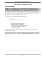
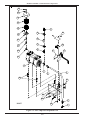
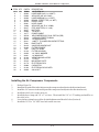
INSTALLER'S MANUAL
CLEAN BURN MODEL: DOUBLE-PISTON AIR COMPRESSOR #14336
Optional Accessories for Clean Burn Furnaces/Boilers
I89056
PUBLICATION DATE: 1/4/10, Rev. 5
CLEAN BURN PART # 43142
IMPORTANT FOR U.S. INSTALLATIONS: All installations must be made in accordance with state and local codes which
may differ from the information provided in this manual. Save these instructions for reference.
IMPORTANT FOR CANADIAN INSTALLATIONS: The installation of this equipment is to be accomplished by qualified
personnel and in accordance with the regulation of authorities having jurisdiction and CSA Standard B 139, Installation
Code for Oil Burning Equipment.
WARRANTY INFORMATION
Clean Burn, Inc., MANUFACTURER, hereby warrants that MANUFACTURER's products shall be free from defect in material
and workmanship under normal use according to the provisions and limitations herein set forth.
MANUFACTURER warrants the heat exchanger/combustion chamber for a period of ten (10) years (or 15,000 hours,
whichever comes first), from the date of purchase by the purchaser, as follows:
If the defect occurs in the first five (5) years (or 7500 hours, whichever comes first) , Clean Burn pays 100% of parts,
replacement or repair (the customer pays 0%), and pro rata thereafter according to the following schedule:
(a) If the defect occurs during the sixth year (or 7500-9000 hours, whichever comes first), customer pays 70% of
parts, replacement or repair.
(b) If the defect occurs during the seventh year (or 9000-10,500 hours, whichever comes first), customer pays 75%
of parts, replacement or repair.
(c) If the defect occurs during the eighth year (or 10,500-12,000 hours, whichever comes first), customer pays 80%
of parts, replacement or repair.
(d) If the defect occurs during the ninth year (or 12,000-13,500 hours, whichever comes first), customer pays 85% of
parts, replacement or repair.
(e) If the defect occurs during the tenth year (or 13,500-15,000 hours, whichever comes first), customer pays 90% of
parts, replacement or repair.
MANUFACTURER warrants all other Clean Burn component parts, including the energy retention disk, for a period of one
(1) year from the date of purchase by the purchaser.
LIMITATIONS:
The obligation of MANUFACTURER for breach of warranty shall be limited to products manufactured by MANUFACTURER (1) that
are installed, operated and maintained according to MANUFACTURER's instructions furnished and/or available to the purchaser upon
request; (2) that are installed according to all other applicable Federal, State and local codes or regulations; and (3) that the purchaser
substantiates were defective in material and workmanship notwithstanding that they were properly installed and correctly maintained as set
forth above and were not abused or misused.
The obligation of MANUFACTURER shall be limited to replacing or repairing the defective product, at the option of the
MANUFACTURER. MANUFACTURER shall not be responsible for any labor or costs of removal or reinstallation of its products and
shall not be liable for transportation costs to and from its plant at Leola, Pennsylvania.
Use of parts for modification or repair of the product or any component part thereof not authorized or manufactured by
MANUFACTURER specifically for such product shall void this warranty.
This warranty shall not apply to any damage to or defect in any of MANUFACTURER's products that is directly or indirectly caused by
(1) force majeure, Act of God or other accident not related to an inherent product defect; or (2) abuse, misuse or neglect of such product,
including any damage caused by improper assembly, installation, adjustment, service, maintenance or faulty instruction of the purchaser.
Other than as expressly set forth hereinabove, MANUFACTURER makes no other warranty, express or implied, with respect to any of
MANUFACTURER's products, including but not limited to any warranty of merchantability or fitness for a particular purpose.
And in no event shall MANUFACTURER be responsible for any incidental or consequential damages of any nature suffered by purchaser
or any other person or entity caused in whole or in part by any defect in any of MANUFACTURER's products. Any person or entity to
whom this warranty extends and who claims breach of warranty against MANUFACTURER must bring suit thereon within one year from
the date of occurrence of such breach of warranty or be forever barred from any and all legal or other remedies for such breach of warranty.
MANUFACTURER is not responsible for and hereby disclaims any undertaking, representation or warranty made by any dealer,
distributor or other person that is inconsistent with or in any way more expansive than the provisions of this limited warranty.
This warranty grants specific legal rights and shall be read in conformity with applicable state law. In some jurisdictions, the applicable law
mandates warranty provisions that provide greater legal rights than those provided for herein. In such case, this limited warranty shall be
read to include such mandated provisions; and any provision herein that is prohibited or unenforceable in any such jurisdiction shall, as to
such jurisdiction, be ineffective to the extent of such prohibition or unenforceability without invalidating the remaining provisions and
without affecting the validity or enforceability of such provision in any other jurisdiction(s).
TRADEMARKS
The Clean Burn logo is a trademark of Clean Burn, Inc. All other brand or product names mentioned are the registered
trademarks or trademarks of their respective owners.
COPYRIGHT
Copyright © 2010 Clean Burn, Inc. All rights reserved. No part of this publication may be reproduced, or distributed without
the prior written permission of Clean Burn, Inc. 34 Zimmerman Road, Leola, PA 17540. Subject to change without notice.
TABLE OF CONTENTS
NOTE: A Special Bulletin (which appears just after the Table of Contents) has been
added to your manual to highlight important information about the installation,
adjustment and operation of your air compressor. Be sure to read this sheet before
beginning any procedures in this manual.
SECTION 1: INTRODUCTION ................................................................................... 1-1
Guide to this Manual .......................................................................................................... 1-1
For Your Safety... .............................................................................................................. 1-2
SECTION 2: UNPACKING ......................................................................................... 2-1
Unpacking and Inspecting All Components ......................................................................... 2-1
SECTION 3: INSTALLING THE AIR COMPRESSOR ............................................... 3-1
Air Compressor Exploded View with Parts List .................................................................. 3-2
Installing the Air Compressor Components ......................................................................... 3-3
Preparing the Furnace Cabinet (Saturn 140 / Saturn 240) .................................................... 3-5
Mounting the Air Compressor (Saturn 140 / Saturn 240) .................................................... 3-5
Preparing the Furnace Cabinet (CB-1750 / CB-2500 / CB-3250) ...................................... 3-7
Mounting the Air Compressor (CB-1750 / CB-2500 / CB-3250) ....................................... 3-7
Preparing the Furnace Cabinet (CB-3500 / CB-5000) ........................................................ 3-9
Mounting the Air Compressor (CB-3500 / CB-5000) ........................................................ 3-9
Mounting the Air Compressor (CB-200-CTB / CB-350-CTB / CB-500-CTB) .................. 3-9
Preparing the CB-500 Series Burner for use with the Air Compressor ............................... 3-10
Connecting the Air Compressor to the CB-500 Series Burner ........................................... 3-12
Wiring the Air Compressor to the CB-500 Series Burner .................................................. 3-12
Preparing the Saturn Burner for use with the Air Compressor ............................................ 3-13
Connecting the Air Compressor to the Saturn Burner ........................................................ 3-14
Wiring the Air Compressor to the Saturn Burner ............................................................... 3-14
SECTION 4: OPERATING & MAINTAINING THE AIR COMPRESSOR ................... 4-1
Adjusting the Air Compressor during Operation .................................................................. 4-1
Maintaining the Air Compressor ......................................................................................... 4-2
APPENDIX A
Technical Reference Materials ........................................................................................... A-1
CB-500 Series Burner Wiring Diagram ....................................................................... A-1
Saturn Burner Wiring Diagram .................................................................................... A-2
Air Compressor Wiring .............................................................................................. A-3
SPECIAL BULLETIN
IMPORTANT INFORMATION CONCERNING THE SERVICE RATING
OF THE AIR COMPRESSOR
Air compressor model #14336 has a service rating of approximately 75%. This means that the air compressor
can operate continuously for approximately 45 minutes (75% of one hour), and then it must not operate for
approximately 15 minutes (25% of one hour) to allow the air compressor to "cool down." This works well for
most furnace/boiler installations where the unit will cycle on and off a few times during an hour.
CAUTION: If the furnace/boiler will run continuously (without cycling on and off a few times
during an hour), you must use an air compressor with a tank. (Refer to the air compressor specifications
for your furnace/boiler when purchasing an air compressor with a tank.) DO NOT use air compressor model
#14336 if your furnace/boiler will run continuously for periods which exceed the 75% service rating.
This will overheat the air compressor and severely damage the teflon rings and teflon skirt in the air compressor,
resulting in poor air pressure output from the compressor.
IMPORTANT INFORMATION CONCERNING ADJUSTMENT
OF THE AIR COMPRESSOR
It is very important to follow the instructions "Adjusting the Air Compressor During Operation" in this
manual. This procedure involves the adjustment of the pressure relief on the air compressor so that the precise
air pressure (12 to 18 psi) required for proper burner operation is provided to the burner. Excess air pressure
is bled off through the pressure relief.
CAUTION: DO NOT run the air compressor without properly adjusting the pressure relief. This will overheat
the air compressor and severely damage the teflon rings and teflon skirt in the air compressor, resulting in poor
air pressure output from the compressor.
IMPORTANT INFORMATION CONCERNING YOUR
AIR COMPRESSOR MODEL
Clean Burn Model #14336 is a double-piston air compressor which can be installed on ALL Clean
Burn furnace and boiler models.
Installer's Manual: Clean Burn Air Compressors
SECTION 1: INTRODUCTION
Guide to this Manual
IMPORTANT! This manual provides all the instructions necessary to install the Clean Burn
air compressor on your Clean Burn furnace or boiler. Refer to your equipment Operator's Manual
for instructions on assembling, installing, operating, and maintaining your furnace or boiler.
Consult the Table of Contents for a detailed list of topics covered in this manual. You'll find the stepby-step procedures easy to follow and understand. Should questions arise, please contact your Clean
Burn dealer before starting any of the procedures in this manual.
Following is an outline of the air compressor installation process:
•
•
UNPACKING
INSTALLING THE AIR COMPRESSOR
• Installing the Air Compressor Components
• Preparing the Furnace Cabinet
• Mounting the Air Compressor (Furnaces)
• Mounting the Air Compressor (Boilers)
• Preparing the Burner for use with the Air Compressor
• Connecting the Air Compressor to the Burner
• Wiring the Air Compressor
Procedures are also provided for adjusting the air compressor during furnace/boiler operation and for
maintaining the air compressor.
Please read all sections carefully--including the following safety information--before beginning any
installation procedures; doing so ensures your safety and the optimal performance of your Clean
Burn air compressor.
1-1
Installer's Manual: Clean Burn Air Compressors
Please read all sections in this manual carefully--including the following safety information--before
beginning any installation procedures; doing so ensures your safety and the optimal performance of
your Clean Burn air compressor and furnace/boiler.
For Your Safety...
For your safety, Clean Burn documentation contains the
following types of safety statements (listed here in order
of increasing intensity):
• NOTE: A clarification of previous
information or additional pertinent
information.
• ATTENTION: A safety statement
indicating that potential equipment damage
may occur if instructions are not followed.
CAUTION: A safety statement
that reminds of safety practices or directs
attention to unsafe practices which could
result in personal injury if proper
precautions are not taken.
WARNING: A strong safety
statement indicating that a hazard exists
which can result in injury or death if proper
precautions are not taken.
DANGER! The utmost levels of
safety must be observed; an extreme hazard
exists which would result in high probability
of death or irreparable serious personal
injury if proper precautions are not taken.
IMPORTANT! Review the list of general safety
precautions provided in Section 1 of your Furnace/
Boiler Operator's Manual. These precautions must
be heeded to ensure proper, safe air compressor and
furnace/boiler operation.
1-2
WARNING!
STOP
YOUR SAFETY IS AT STAKE!
DO NOT INSTALL, OPERATE, OR
MAINTAIN THIS EQUIPMENT
WITHOUT FIRST READING
AND UNDERSTANDING
THIS MANUAL!
Installer's Manual: Clean Burn Air Compressors
SECTION 2: UNPACKING
Before installing the air compressor on your furnace/boiler, you should take some time to carefully unpack your
shipment from Clean Burn.
Unpacking and Inspecting All Components
Carefully open all shipping containers and inspect all components. Immediately notify the freight
company and your Clean Burn dealer in case of shipping damage or shortage(s). Keep all components
together so you will have them as needed for assembly and installation.
For your convenience, air compressor components are listed in Section 3 (in related groupings)
throughout the installation process. Detailed illustrations with labelled components should enable
easy assembly/installation.
2-1
Installer's Manual: Clean Burn Air Compressors
2-2
Installer's Manual: Clean Burn Air Compressors
SECTION 3: INSTALLING THE AIR COMPRESSOR
IMPORTANT! If you are installing your furnace/boiler and air compressor at the same time, Clean
Burn recommends the following sequence of activities:
1. Assembly of Furnace/Boiler (for furnace - through the installation of mounting/stabilizer brackets).
2. Installation of Air Compressor on Furnace/Boiler
3. Installation of Furnace/Boiler (including oil pump, wiring, oil/air lines, stack, thermostat)
Keep the Furnace/Boiler Operator's Manual handy for quick reference as specified throughout the installation of
the air compressor.
WARNING: If you have already installed your furnace/boiler and power has been connected
to the unit, ensure that the power is turned OFF before proceeding with the installation of the air
compressor to avoid electrical shock hazards.
3-1
Installer's Manual: Clean Burn Air Compressors
23
22
21
20
19
10
9
18
29
8
17
7
16
28
6
15
27
12
14
13
5
3
4
24
30
26
25
I89055
2
11
Figure 3A - Air Compressor Exploded View
3-2
1
Installer's Manual: Clean Burn Air Compressors
ITEM QTY
1
1
2
1
3
1
4
1
5
1
6
1
7
1
8
1
9
1
1
10
11
4
12
1
13
1
14
1
15
1
16
1
17
1
18
1
19
1
20
1
21
1
22
1
23
1
24
4
25
2
26
1
27
1
28
1
29
1
30
4
PART#
32280
32234
54063
32236
32233
32146
32091
13063
32147
32157
34092
12177
32518
32210
32150
32411
70341
32412
32409
N/A
21130
34182
34181
31104
21075
25120
21179
33383
21180
34009
DESCRIPTION
1/8" ELBOW 90°
HOSE BARB (3/8" H x 1/8"NPT)
AIR HOSE (3/8",42" LONG)
HOSE BARB(3/8"H x 1/4" NPT)
BRASS STREET TEE (1/4" NPT)
RELIEF VALVE
HOSE CLAMP
AIR HOSE (3/8" ID, 3" LONG)
PIPE ADAPTER (1/2" x 3/8")
MUFFLER
1/4−20 NUT
POWER CABLE
AIR COMPRESSOR− DUAL PISTON (75R)
1/4 BRASS STREET ELBOW
1/4 BRASS NIPPLE
1/4NPT F TO 3/8NPS BULKHEAD FITTING
BASE PLATE
3/8 NPS BULKHEAD NUT
FILTER ELEMENT
PART OF 32409
FILTER HOUSING
1/4" VINYL WASHER
1/4" WING NUT
VIBRATION INSULATOR
"U" BOLT
MOUNTING PLATE
ELECTRICAL BOX
CAPACITOR
ELECTRICAL BOX COVER
3/8−16 NUT
Installing the Air Compressor Components
1.
2.
3.
4.
5.
6.
7.
Refer to Figure 3A.
Install the air intake filter in the inlet port on the compressor head (notice the directional arrow).
Install the 1/4" street tee in the outlet port of the compressor head (notice the directional arrow).
Install the relief valve on the street tee.
Install the hose clamp and 3/8" x 3" air hose. Then install the 3/8" x 1/2" bushing and muffler on
the relief valve.
Leave the hose clamp loose to allow for initial adjustment of the relief valve (Section 4).
Install the 3/8" H x 1/4" NPT hose barb on the street tee.
3-3
Installer's Manual: Clean Burn Air Compressors
I89060
Figure 3B - Air Compressor Installed on the Saturn 140 / Saturn 240
3-4
Installer's Manual: Clean Burn Air Compressors
Preparing the Furnace Cabinet (Furnace Models Saturn 140 / 240)
1.
2.
Refer to Figures 3A and 3B.
Install all-thread rods through the mounting holes in the base and top of the furnace cabinet. Use double
nuts to securely lock the all-thread rods in position.
Mounting the Air Compressor (Furnace Models Saturn 140 / 240)
CAUTION: The compressor must be securely mounted as described in this section. Ensure that
all nuts and bolts are firmly tightened.
1.
2.
Refer to Figure 3A and 3B.
While facing the burner side of the furnace, install the air compressor on the front right all-thread rod
using the two U-bolts and nuts provided. Position the mounting bracket approximately two inches
above the top of the furnace cabinet.
3-5
Installer's Manual: Clean Burn Air Compressors
I89056
Figure 3C - Air Compressor Installed on the CB-1750 / CB-2500 / CB-3250
3-6
Installer's Manual: Clean Burn Air Compressors
Preparing the Furnace Cabinet (Furnace Models CB-1750/2500/3250)
1.
2.
Refer to Figures 3A and 3C.
Install all-thread rods in the mounting lugs on top of the furnace cabinet. Use double nuts to
securely lock the all-thread rods in position.
Mounting the Air Compressor (Furnace Models CB-1750/2500/3250)
CAUTION: The compressor must be securely mounted as described in this section. Ensure that
all nuts and bolts are firmly tightened.
1.
2.
Refer to Figure 3A and 3C.
While facing the burner side of the furnace, install the air compressor on the front right all-thread rod
using the two U-bolts and nuts provided. Position the mounting bracket approximately two inches
above the top of the furnace cabinet.
3-7
Installer's Manual: Clean Burn Air Compressors
I89058
Figure 3D - Air Compressor Installed on the CB-3500 / CB-5000
3-8
Installer's Manual: Clean Burn Air Compressors
Preparing the Furnace Cabinet (Furnace Models CB-3500 and CB-5000)
1.
2.
3.
Refer to Figures 3A/3D and your Furnace Operator's Manual for an overview of furnace assembly
(refer specifically to information on the installation of the mounting/stabilizer brackets and
the all-thread rods).
According to the Furnace Operator's Manual, install the mounting and stabilizer brackets which
hold the all-thread rods in place.
Install all-thread rods through the channels in the furnace cabinet as described in the Furnace
Operator's Manual. Use washers and double nuts to securely lock the all-thread rods in position.
NOTE: The air compressor will be installed on one of the forward all-thread rods as illustrated
in Figure 3D.
Mounting the Air Compressor (Furnace Models CB-3500 and CB-5000)
CAUTION: The compressor must be securely mounted as described in this section. Ensure that
all nuts and bolts are firmly tightened.
1.
2.
Refer to Figures 3A and 3D.
While facing the burner side of the furnace, install the air compressor on the front right all-thread rod
using the two U-bolts and nuts provided. Position the mounting bracket a few inches below the
stabilizer bracket as shown in Figure 3D.
Mounting the Air Compressor
(Boiler Models CB-200-CTB / CB-350-CTB / CB-500-CTB)
CAUTION: The compressor must be securely mounted as described in this section. Ensure that
all nuts and bolts are firmly tightened.
1.
2.
Refer to the previous illustrations. The air compressor configuration on a boiler is similar to that shown
on the furnace illustrations.
Install the air compressor on an adjacent wall at least (2) two feet from the boiler
(due to temperature requirements).
3-9
Installer's Manual: Clean Burn Air Compressors
Preparing the CB-500 Series Burner for use with the Air Compressor
AIR REGULATOR
AIR GAUGE
OIL GAUGE
COMBUSTION
AIR BAND
I89062
Figure 3E - Component Detail of the CB-500 Series Burner
WARNING: To avoid electrical shock hazards, turn off all power to the furnace, and unplug the
burner before proceeding.
1.
2.
3.
4.
5.
6.
7.
Figure 3E shows an exterior view of the CB-500 series burner components. In this procedure, you will
be removing the air regulator from the preheater block assembly to prepare the CB-500 series burner
for use with the air compressor assembly #14336.
Remove the self-tapping screw with a 1/4" nut driver and swing open the double-hinged lid to expose
the heater block assembly.
Refer to Figure 3F. Use a 1/8" Allen wrench to loosen the locking bolt on the locking bar.
Remove the locking bar.
Use a 5/32" Allen wrench to remove the four (4) bolts and washers holding the surface-mounted air
regulator in place, then carefully remove the air regulator.
DO NOT allow any debris to fall into the air passageways which have been exposed by the removal of
the air regulator.
Install the square cap with the o-ring using the four (4) bolts and washers. Tighten the four bolts
firmly in a crisscross pattern to ensure that there are no leaks.
3-10
Installer's Manual: Clean Burn Air Compressors
Preparing the CB-500 Series Burner for use with the Air Compressor
(continued)
LOCKING BAR
SAVE AND USE THESE 4
SCREWS AND WASHERS
TO INSTALL SQUARE CAP
STEP 1
SURFACE MOUNTED
AIR REGULATOR
REMOVE
THESE PARTS
(COMPLETE
REGULATOR)
STEP 2
10
9
8
7
6
5
4
3
2
1
INSTALL
SQUARE CAP
AND "O" RING
I89061
Figure 3F - Removing the Air Regulator from the Heater Block on the CB-500 Series Burner
3-11
Installer's Manual: Clean Burn Air Compressors
Connecting the Air Compressor to the CB-500 Series Burner
IMPORTANT: Run the 3/8" air hose directly from the air compressor to the burner.
Do not use the connector block.
1.
2.
3.
4.
5.
Refer to Figure 3G.
Remove the female elbow 1/4" tube push fitting from the air pressure inlet port on the burner.
Install the supplied 1/8" elbow on the air pressure inlet port of the burner.
Install the 3/8" H x 1/8" NPT hose barb in the elbow on the air pressure inlet port of the burner.
Push the hose onto the hose barbs at the air compressor and the burner inlet port.
CAUTION: To prevent possible injury during operation, ensure that the hose is fully inserted
over the stems of the hose barbs so that it does not come loose during operation.
Wiring the Air Compressor to the CB-500 Series Burner
CAUTION: The installation of the air compressor will increase the total amperage draw by
approximately 3.5 amps. Ensure that your furnace/boiler wiring can safely accommodate this addition.
1.
2.
3.
4.
5.
Refer to Figure 3G.
Install the electrical power cable into the electrical junction box beside the compressor on the mounting
bracket.
Connect the wires according to the label on the electrical box lid and the illustration in Appendix A of
this manual.
Connect the electrical cable to the 7/8" electrical access on the side of the burner.
Connect the wires at the terminal strip in the burner box according to the burner wiring schematic
provided in Appendix A of this manual.
AIR HOSE FROM AIR COMPRESSOR
INSTALLED ON 3/8" HOSE BARB FITTING
REMOVE THE PLASTIC SNAP−ON CAP
FROM THE HOLE IN THE SIDE OF THE
BURNER AND INSTALL THE CONNECTOR
WITH POWER CABLE FROM THE
AIR COMPRESSOR
OIL LINE FROM CONNECTOR
BLOCK INSTALLED ON OIL
LINE PORT OF THE BURNER
1/8" ELBOW INSTALLED ON
BURNER AIR INLET NIPPLE
I88532−A
Figure 3G - Connecting the Air Compressor Hose and Electrical Cable to the Burner
3-12
Installer's Manual: Clean Burn Air Compressors
Preparing the Saturn Burner for use with the Air Compressor
ELECTRICAL
BOX COVER
AIR
REGULATOR
COMBUSTION
AIR BAND
I88584−A
Figure 3H - Component Detail of the Saturn Burner
WARNING: To avoid electrical shock hazards, turn off all power to the furnace, and unplug the
burner before proceeding.
1.
2.
3.
4.
5.
6.
7.
Figure 3H shows an exterior view of the Saturn burner components. In this procedure, you will be
removing the internal air regulator components to prepare the Saturn burner for use with the air
compressor assembly #14336.
Remove the self-tapping screws with a 1/4" nut driver and open the electrical box cover to expose
the air regulator assembly.
Refer to Figure 3I. Loosen the 3/4" nut on the air regulator bonnet and slide the air regulator assembly
out of the electrical box.
Unscrew the air regulator bonnet from the body.
Use a 1/2" nut driver to remove the brass poppet seat and o-ring from the air regulator body. Also
remove the poppet valve and poppet spring.
Reinstall the bonnet on the regulator body with the diaphram in place to make an air tight seal.
Reinstall the air regulator assembly and electrical box cover.
3-13
Installer's Manual: Clean Burn Air Compressors
ITEM # PART# DESCRIPTION
1
32221 POPPET SPRING
2
32222 POPPET VALVE
3
32223 POPPET O−RING
4
32305 BRASS SEAT
5
32225 DIAPHRAM
6
32226 DIAPHRAM RING
7
33308 BONNET
8
34145 3/4" PANEL NUT
9
32202 1/4T PUSH X 1/8 NPT FEM ELBOW
7
6
R
4
O
EM
3
VE
1
2
5
9
8
REMOVE
I89063
Figure 3I - Removing the Air Regulator Components on the Saturn Burner
Connecting the Air Compressor to the Saturn Burner
IMPORTANT: Run the 3/8" air hose directly from the air compressor to the burner.
Do not use the connector block.
1.
2.
3.
4.
5.
Refer to Figure 3I.
Remove the female elbow 1/4" tube push fitting from the air pressure inlet port on the burner.
Install the supplied 1/8" elbow on the air pressure inlet port of the burner.
Install the 3/8" H x 1/8" NPT hose barb in the elbow on the air pressure inlet port of the burner.
Push the hose onto the hose barbs at the air compressor and the burner inlet port.
CAUTION: To prevent possible injury during operation, ensure that the hose is fully inserted
over the stems of the hose barbs so that it does not come loose during operation.
Wiring the Air Compressor to the Saturn Burner
CAUTION: The installation of the air compressor will increase the total amperage draw by
approximately 3.5 amps. Ensure that your furnace/boiler wiring can safely accommodate this addition.
1.
2.
3.
4.
Install the electrical power cable into the electrical junction box beside the compressor on the mounting
bracket.
Connect the wires according to the label on the electrical box lid and the illustration in Appendix A of
this manual.
Connect the electrical cable to the 7/8" electrical access hole on the bottom side of the Saturn burner.
Connect the wires at the terminal strip in the burner box according to the burner wiring schematic
provided in Appendix A of this manual.
3-14
Installer's Manual: Clean Burn Air Compressors
SECTION 4: OPERATING & MAINTAINING
THE AIR COMPRESSOR
Adjusting the Air Compressor During Operation
It is very important to adjust the pressure relief on the air
compressor to provide the burner with the precise air
pressure (12 to 18 psi) required for proper burner operation. Excess air pressure is bled off through the pressure
relief.
ATTENTION: DO NOT run the air compressor with the
air regulator installed (see section 3 - Preparing the Burner
For Operation With the Air Compressor). This may cause
the compressor to overheat and severely damage the teflon
rings and teflon skirt in the air compressor, resulting in poor
air pressure output from the compressor.
1.
2.
3.
4.
5.
Refer to your heating equipment's Operator's
Manual, Section 6 "Burner Start Up and
Adjustment". Note the proper air pressure
setting. (e.g. CB-2500 furnace requires an air
pressure setting of 12 - 18 psi.)
Follow the directions in Section 6 of your heating
equipment'sOperator's Manual to start the burner.
Loosen the locking nut and slowly back out the
adjustment on the pressure relief valve on the air
compressor to supply proper air pressure to the
burner.
NOTE: The air gauge on the burner may
"bounce" slightly when compressed air is being
supplied by a piston air compressor.
Firmly tighten the lock-down nut on the
pressure relief.
Be sure to install the sound dampening assembly
over the pressure relief. This will "muffle" the
sound of the air pressure escaping through the
pressure relief.
SOUND
DAMPING
ASSEMBLY
LOCKING NUT
PRESSURE
RELEIF VALVE
TEE IN
COMPRESSOR
OUTLET
I89059
Figure 4A - Pressure Relief Valve Assembly
4-1
Installer's Manual: Clean Burn Air Compressors
Maintaining the Air Compressor
ATTENTION: Never introduce oil into the head of the air compressor. Oil will damage the teflon
seals of the air compressor and will void your warranty.
1.
2.
Clean the air intake filter element at least monthly according to the manufacturer's instructions
included with the filter.
Replace the air intake filter element annually.
ATTENTION: DO NOT operate the air compressor with a dirty air intake filter; doing so may
seriously damage the air compressor.
1/4" WING NUT
1/4" VINYL WASHER
COVER HOUSING
FILTER MESH
FILTER ELEMENT
3/8 NPS BULKHEAD NUT
BASE PLATE
I88869
Figure 4B -Air Intake Filter Assembly
4-2
140 WATTS NOZZLE HEATER
WALL
THERMO−
STAT
NOZZLE
TEMP.SW.
RED
BLACK
BLACK
RED
AIR
SOLENOID
OIL
SOLENOID
CAD CELL
YELLOW
TRANS−
PRIMARY
OIL
FORMER
BLACK
140
BLUE
ORANGE
WHITE
MOTOR
BURNER
WHITE
JUMPERS
WHITE
1 2 3 4 5 6
9 10 11 12 13
F F T T
FIGURE A1 - Burner Wiring Schematic (Similar for all CB-500 Series burners)
I88249−B
CAPACITOR
BROWN
BROWN
7 8
GREEN
GREEN
LIGHT
CENTRIFUGAL
SWITCH
A-1
YELLOW
BLACK
AMBER
LIGHT
PREHEATER THERMOSTAT
BLACK
BROWN
METER
HOUR
BLUE
WHITE
AIR
SWITCH
N.O.
(OPTIONAL)
COMPRESSOR
AIR
BLOCK HEATER 400 WATTS
TO RELEASE OR INSTALL A WIRE, CAREFULLY PUSH THE
BLADE OF THE SCREWDRIVER INTO THE RELEASE SLOT
ON THE TERMINAL STRIP UNTIL YOU FEEL THE JAWS "SNAP"
WIDE OPEN. LEAVE THE BLADE IN THE RELEASE SLOT TO
REMOVE OR INSTALL A WIRE. TO RELEASE THE JAWS,
CAREFULLY PULL THE BLADE OF THE SCREWDRIVER
FROM THE RELEASE SLOT.
NOTE: WHEN RELEASING OR INSTALLING WIRES ON THE
TERMINAL STRIP USE THE SMALL SCREWDRIVER SUPPLIED
WITH THE BURNER TO RELEASE THE TERMINAL JAWS.
TO LOCATE THE SCREWDRIVER, OPEN THE HINGED ACCESS
PLATE ON THE TOP OF THE BURNER. THE SCREWDRIVER
IS CLIPPED TO THE INSIDE OF THE BURNER HOUSING
ON THE RIGHT.
BLACK
BLACK
RED
PROVING SWITCH 120° N.O.
BLACK
CONNECTOR (FACE)
Installer's Manual: Clean Burn Air Compressors
APPENDIX A
Technical Reference Materials
FIGURE A2 - Saturn Burner Wiring Schematic
A-2
OIL
SOLENOID
WALL
THERMO−
STAT
BLACK
YELLOW
CAD
CELL
TEMP
SWITCH
L−150 N C
BLACK
BLACK
BLACK
GREY
WIRENUT
PROVING
SWITCH
WHITE
F F
PRIMARY
OIL
BLUE
ORANGE
WHITE
SOLENOID
AIR
BLACK
AIR
SWITCH
N.O.
BLACK
BLACK
AIR
COMPRESSOR
(OPTIONAL)
TRANS−
FORMER
BLACK
ORANGE
BLACK
RED
RED
WHITE
GRN
TO OIL
PUMP
PUR
PUR
BLOCK HEATER 250 WATTS
YELL
WHITE
RED
L2
9 10 11 12 13
7 8
MOTOR
WHITE
PUR
RED
BLACK
WHITE
WHITE
WHITE
WHITE
RED
42378
JUMPER
TO BURNER HI
LIMIT SWITCH
BURNER
G
1 2 3 4 5 6
L1
Installer's Manual: Clean Burn Air Compressors
BK
Installer's Manual: Clean Burn Air Compressors
DOUBLE PISTON AIR COMPRESSOR WIRING
ORANGE WIRENUTS
BLUE
WHITE
WHITE
BLUE
FLEX
CONDUIT
BROWN
CONNECT ONE END OF THE GROUND WIRE TO
THE GROUND SCREW ON THE COMPRESSOR
AND THE OTHER END TO THE SCREW ON THE
OUTSIDE OF THE JUNCTION BOX
CAPACITOR
TO TERMINAL BLOCK INSIDE
THE BURNER HOUSING
FIGURE A3 - Double-Piston Air Compressor Wiring
A-3
I88533−A
Installer's Manual: Clean Burn Air Compressors
A-4