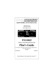
1
1. INTRODUCTION
A. THE CLEAR-COM CONCEPT
Clear-Com is a closed-circuit intercom system
that provides highintelligibility, two-way communications in high- or low-noise environments.
A basic intercom system
contains a one- or multi-channel
Main Station interconnected with
various remote headset and speaker
stations.
mic input lines (200 ohms) and
specially designed circuitry make
Clear-Com channels virtually immune
to RF and dimmer noise.
Clear-Com Main Stations, Power Supplies, and some Remote Stations
provide an auxiliary program input
with its own volume control, which
al lows
Clear-Com manufactures a wide variety of portable, rack-mount, and
custom-mount intercoms.
All are
compatible, allowing systems to be
set up according to specific needs.
The
Clear-Com System interfaces
with virtually any other type of
communications systems (call ClearCon or see your dealer for info).
Clear-Com Stations normally interconnect with standard, 2-conductor
shielded microphone cable;
they
include inputs for XLR-type, 3-pin
connectors.
One wire in the mic
cable
carries DC power
(28-30
volts) from the Main Station to the
remote stations, and the other wire
carries
the audio signal.
The
shield acts as common ground.
Audio termination is required at only
one point in the intercom system,
and is usually provided by the Main
Station or Power Supply.
Clear-Com is a "distributed amplifier system:" each main and remote
station contains its own mic pream
plifier, power amplifier (for headset or speaker), and signalling
circuitry. Every intercom has Automatic Headset Detection, a circuit
that shuts off the mic preamp when
the mic or headset is not connected, so background noise is not
increased by an unused but on-line
(connected) station. Low-impedance
the
station
operator
to
monitor external audio.
Visual Signal Circuitry, a standard
feature on most stations, allows
the user to attract the attention
of operators who have removed their
headsets or turned off their speakers.
Depending upon the type of Main and
Remote Stations selected, a maximum
amount of Remote Stations from 12
(speaker) to 100 (headset) can be
connected along one mile of wire.
Remote Stations bridge the intercom
line at a very high impedance, and
place a minimum load on the line.
Audio level remains constant, never
fluctuating
even when
stations
leave or join the line.
The regulated DC voltage provided
by
Main Stations and Power Supplies enables remote stations to
operate; they run at minimal current (10 milliamperes quiescent for
headset stations, 20 ma quiescent
for speaker stations) while generating extremely loud listen volumes
(greater than 110 dB SPL). The
higher voltage and low current keep
voltage losses to a minimum in long
lines. If the voltage drops due to
the addition of cable or many stations, Clear-Com equipment continues operating normally with less
than 12 volts available.
breaker pops out and the adjacent
red LED illuminates.
Removing the
short,
then pressing the circuitbreaker button automatically resets
the system.
The CS-210 provides audio termination for the intercom system.
The CS-210 can be ganged together
with other CS-210's for multiple
two-channel systems and
back-up
power support.
The unit is lightweight,
weather-resistant, and assembled with a sturdy plastic carrying strap on top and four protective rubber feet on the bottom of
its weather-resistant enclosure.
Easy Interconnection
The CS-210 provides three 3-pin,
male XLR outputs for output of
Channel A (connectors are wired in
parallel) and three of the same for
Channel B output.
Intercom signals
are
fed from the CS-210
with
standard
mic cable;
see
next
section.
The CS-210 is available with a
rack-mount kit for adapting it
to
standard 19" equipment racks.
The
Clear-Com part number for the CS210 Rack-Ear Kit is 820020.
3
mflMZ
1
m
)
z mc
<I0-
a
CM
Zm
n
~
~
0
~
_
rm
z~~~~~~~~~~~~~~~~~~~~~~~C
00
O-4m
Z,z
zw-c
m~~4~f
0
m
z~~~zn
z
-4~~~~m
..
X 17
Xt|
2 OM
r
0
Z
~~~x
__
cn4
M)
logo
4o
O'2
C)~~~~l
0
z O-~~~-
*0
a~~
0
z
CD
z
z
11. SYSTEM INTERCONNECTION
A. INPUTS & OUTPUTS: WHAT CABLE TO USE
Intercom Output to the System
Each intercom channel is output from the CS-210 on standard two-conductor mic cable. The cable is routed from the 3-pin male XLR connectors
on the CS-210 rear panel to the 3-pin female XLR input connectors on
the Remote Stations. One cable wire carries DC power and the other
wire carries the intercom signal; the shield acts as circuit ground.
The pin assignments on ALL 3-pin
female) are:
PIN 1-PIN 2-PIN 3--
XLR intercom connectors (male and
COMMON
+ VDC
INTERCOM AUDIO (Channel A or B)
Choosing Cable
The CS-210 provides three output connectors for each channel, so each
channel can be routed separately (in individual mic cables) or combined
from one Channel A output and one Channel B output onto multi-pair
cable. The latter is most convenient when connecting to the input
terminal strips of Clear-Com's wall- or custom-mount two-channel stations (such as KB-IIIA or MR-102A).
These methods, of course, can be combined in the same system.
When choosing interconnecting cable, keep the fol lowing considerations
in mind:
1) DC resistance affects crosstalk. In permanent installations, do not use wire smaller than 20 gauge, stranded
(except runs shorter than 100 feet). Keep the total resistance under 100 ohms.
2) The capacitance of the interconnecting cable affects the
frequency response and sidetone stability. Total capacitance should not be greater than .25 microfarads (capacitance between conductor and shield; equivalent to an
intercom network containing 5000 feet of 50 pF per foot of
cable).
3) Clear-Com Systems operate with cable that has no more
than 50 pF from conductor to conductor, and no more than 70
pF from conductor to shield.
PORTABLE INSTALLATION CABLE
Typical cable for connecting the CS-210 to the Remote Stations is
rubber-jacketed, two-conductor, shielded microphone cable. We suggest
you try:
BELDEN 8413 (24 gauge, stranded) for intercom lines up to 500 feet in
length, and
BELDEN 8412 (20 gauge, stranded)
for lines up to 5000 feet.*
(continued)
5
SYSTEM INTERCONNECTION, CONTINUED
Portable Interconnection Methods
Portable Remote Stations each have a pair of input and output connectors which are wired in parallel, allowing you to set up a "daisychain" when instal lating the system. A diagram in this section illustrates the daisy-chain method. As an alternative, Clear-Com's Model
QP-100 "Quadropuss Line-Splitter" is a small interconnect device that
accepts one cable input and provides three outputs. Both the daisychain and line-splitting methods lessen the cable needed and simplify
the installation process.
PERMANENT INSTALLATION CABLE
To install wall-mount and custom-mount remote stations, we recommend
you use vinyl-insulated and jacketed cable;
it costs less and is
easier to pull through conduit than the rubber-insulated cable. Use
low capacitance cable. We suggest you try:
BELDEN 8762 (20 gauge, stranded) for applications up to 500 feet, and
BELDEN 8760 (18 gauge, stranded) for up to 5000 feet.*
If conduit is avai lable when installing permanent Remote Stations, run
interconnect cable through the conduits to each wall-mounted unit.
NOTE: "Signal ground" (Pin I on intercom connectors) and "chassis
ground" are NOT the same point. Do NOT connect Pin I and the chassis
together.
The chassis is insulated from the signal ground with a
capacitor (.01 microfarad, 1.4kv). This eliminates the hum and potential shock hazards that can arise if stations are at a different ground
potential.
In installations where conduit is NOT used, and equipment doesn't share
a common ground, it is good engineering practice to run an additional
ground wire to tie all chasses together (this decreases susceptibility
to electrical noise fields).
*If you choose not to use Belden cable, use an equivalent type with
similar wire gauge and capacitance. Cable, especially in longer runs,
should have low DC resistance (less than 15 ohms per 1000 feet; large
diameter conductors) and low interconductor capacitance (less than or
equal to 50 pF per foot of cable: capacitance between conductor and shield).
Multi-Channel Cable Considerations
When installing a system that includes two-channel (or more) stations,
each channel may be routed individually to the remote station with
separate mic cables, OR two channels may be routed together with twopair, individually-shielded cable (Belden 8723).
Crosstalk
When multiple channels are fed to remote stations, the amount of crosstalk is proportional to the amount of DC resistance in the ground
return. Two ohms of resistance or less is ideal; 2 ohms will give you
40 dB of isolation. Anything greater than 2 ohms will increase crosstalk. Each channel must be fed in its own separate shield. Tie any
unused wires in the interconnect cable to ground (Pin 1), thereby
further improving the crosstalk.
6
Before you install the system, consider the fol lowing poi nters to help determine
how to configure the intercom connections.
Multiple Power Sources:
Clear-Com Main Stations and Power
Supplies can be paralleled together
in an intercom system;
having an
extra source provides
i ncreased
current capability
(you can add
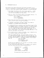
Loop-Through Method:
The common method to interconnect
stations is with a daisy-chain, as
shown here (using one channel):
n
REMOTE
CS 210A
STATIONS
n
more stations to the mile of cable)B
and a back-up power
supply.
If
using
two
sources of DC power,
termination
for the system must
occur in one source only;
the termination switch(es) should be
ON
in one Main Station and OFF
in the
other. See diagram.
CS-210ffi
AUDIO
1 _
9.ce-u> = _ (-30 VDC
tstm~xioscszCOMlMON
TO-21CL_ l
i=F
e C
}SYSTEM
Q
"DAISY-CHAlNS'
This works well,
but if the
line
were
broken anywhere along the
feed, all communicating would stop.
An alternative (shown below) solves
a potential problem by using TWO
Channel A (or B, etc) output connectors for one stretch of cable.
If the line were cut at one point,
activity on the channel continues.
CS-20
DUEL-POWER SETUP DOUBLES SYSTEM
CAPACITY 4 PROVIDES BACK-UP POWER
LOOP-
>-;,THROUGH
B
Signalling Configurations in Multi-Channel Systems:
In normal circumstances, the Call
nel
A stations or Channel B stalight on a two-channel
selectable
tions send a signal.
remote station (which communicates
on one channel at a time)
illumiThe diagram below shows a group of
nates only when someone sends a
two-channel
stations talking
on
signal on the channel
currently
Channel B who want to receive call
being used by that station, not the
signals from stations using Channel
other.
This is because the Call
A (this is one-way
signalling
signal
travels on the
intercom
Channel
B cannot send a signal
to
audio
line (in the form of DC volChannel A).
tage).
This is accomplished by placing
However, you can MODIFY the twofour diodes (914-type) in series on
channel cable that
is
input to
the two-channel
intercom line as
multi-channel
stations
(KB-IIIA,
shown. The call signal follows the
RM-120A, MR-102A) so that, no matdirection of the diodes. Call sigter what channel that group of
naIling is now possible from "A"
stations
is using,
their Call
stations to "B" stations.
lights will go on when either ChanALTERNATIVE SIGNALLING
:IODE ( /
924sl
Tyk.
,'..
1O
'
B. THE CS-210 MAIN STATION
The CS-210 is a portable, twochannel main station with a regulated power supply and a versatile
monitoring system.
It features
excel lent speech intelligibility in
all noise-levels.
The CS-210 contains a mic preamp
with a limiter and can support two
dynamic
headsets/handsets.
The
headset output connector label led
"headset 1" is switchable, with is
a toggle switch that sets the "mic
on" "mic off" and "momentary mic on
'(on)'."
The CS-210's four-watt
power amp can drive a standard
Clear-Com headset to levels greater
than 110 dB SPL.
Monitoring System
The CS-210 provides DC voltage and
the ability to talk & listen on two
separate channels. It supports and
monitors two intercom lines containing as many as 60 remote headset or 12 remote speaker stations.
The CS-210 operator monitors the
intercom channels by pressing the
locking "Monitor Select" buttons
(one for Channel A, one for Channel
B). These buttons light dimly when
engaged.
Either channel may be
monitored separately, or both simultaneously (without tying the two
channels together).
The CS-210
controls the headset listen level
of channel activity with a Volume
knob on the front panel.
Stage Announce (Paging)
On its rear panel, the CS-210 provides an output (line-level, balanced) from the mic preamp.
The
"Stage Announce" button on
the
front panel activates this output,
allowing the CS-210 operator to
speak into the mic or handset and
obtain access to an external speaker/amp system. The Stage Announce
button also mutes the operator's
continued
2
voice output to the intercom
nels.
chan-
Cal t Siqnal linq
Visual
"Call" Signalling attracts
the attention of people who have
removed their headsets or turned
off their speakers.
The CS-210
front panel provides a "Call" button.
Pressing it signals the stations on any channel whose "Monitor
Select" button is engaged and illuminated.
When a remote station sends a Cal I
signal, the lamp in the Monitor
Select button associated with that
station's channel lights brightly,
whether or not the Monitor is "on."
Program input
The CS-210 accepts a balanced, miclevel OR line-level program input
which can be monitored in the headset(s).
The external program is
assignable to either or both channels, and mixes with the intercom
signal.
Program volume for the
operator's headset is adjustable
with a knob on the front panel.
Sidetone
The Sidetone Adjust control on the
front panel allows the CS-210 operator to vary the level of his/her
own voice as heard in the headset;
lowering the amount of sidetone
helps suppress acoustic feedback
when using the CS-210 with an external speaker and a gooseneck mic.
Power Supply Protection
The CS-210 power supply is regulated, current-limited, and provides 30 volts DC at one ampere
from a 115V or 230V (switch-selectable) AC mains supply. The CS-210
has a circuit breaker to protect
the system from miswired cable or
shorts in the lines. If a short
occurs, the front panel circuit
B.
INTERCONNECTION SET-UP
After determining system configuration and channel assignment, pick a
location for the CS-210; it can be anywhere as long as it is provided with
a source of 105-125 VAC, 50-60 Hz (power consumption is 60 watts maximum).
1) Use standard shielded mic cable (see previous section).
ALWAYS
AVOID BENDS IN THE CABLING; allow at least 3" behind rack-mount
units for cable extending from rear panels.
2) Route all cables from the Main Station to the Remote Stations.
assignments on ALL 3-pin intercom connectors are:
PIN 1-- common
PIN 2-- +30 volts DC
PIN 3-- intercom audio
Pin
3) Route cables away from heavy AC power sources, such as lighting
panels, electric motors, or power transformers.
4) In permanent installations, BE SURE TO INSTALL THE SYSTEM IN
ACCORDANCE WITH APPROVED LOCAL BUILDING CODE.
5) If program monitoring is required, input the external signal to the
3-pin female connector on the CS-210 rear panel. The station operator hears the program in the headset, mixed with the intercom activity. The program pre-amp's gain is switch-selectable (on rear
panel) for either mic level (-75dBv nominal input signal) or linelevel (-15dBv nominal). The input must be balanced 300k ohms in line
position, 3-6k ohms in mic position.
6) Turn on power switch (it should illuminate), plug in headset(s) and
set Intercom, Program, and Sidetone levels.
NOTE about HEADSETS AND MICS: The CS-210 headset connectors (like
all Clear-Com dynamic headset connectors) are 4-pin, male XLR. The
connector label led "Headset I" works with the Mic On/Off/(Momentary
On) toggle switch above it. The headset connector pin-out assignment is:
PIN 1--mic common
PIN 2--mic hot
PIN 3--headphone common
PIN 4--headphone hot
DO NOT place the headset(s) within two feet of an AC power transformer or the mic(s) will pick up a hum.
To meet optimum performance specs, the the headsets used (handsets,
mics, etc) should have the following characteristics:
Microphone type:
dynamic
Impedance:
150-250 ohms
Output Level:
-55 dB
Headphone Type:
dynamic
Output Impedance: 300-2000 ohms
The system should now be ready to run!
I
A
.. ..... m0mcS
AA J<
cw
S(FI
MoTlW.j2 rs
MIX~~~~~~~~~~~~~~~~~~~~~~~~1
WroWuIe2 smepalt
CSC1
Im~~~~~~~~~~~.. ...
~
[W~~~~~~~~~~l
~
r
p
or e1 i
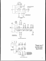
TOURING INTERCOM SYSTEM
(Portable)
o Sirnrge
Ado
VIDEO
CONTROL
CS5|o
AA
OpliWoi1: Ueril AC.ID
in AodioPrdeO Cronlelri w
STTlTdrl
t
TELEVISION INTERCOM SYSTEM
-
----
- -F-C-S-@
.
s>_0
E
SSystem
@
PRODUCTION C5a219
MANAGER
"Typical"
Intercom
PROGUCTION
AREA
.
... .
~~~~~~~~~~~~~~~~~~r..,
,_o. C-iier
E~~~~~~~~~~~~~~~~~~~~~ii
;er
Ioe
MACNINEAREA
FACTORY INTERCOM SYSTEM
ris
r.n
srri
.... oi :' r:i ors
o
s
111. OPERATION OF THE CS-210 MAIN STATION
A. Front Panel Controls and Connectors
The CS-210 controls and connectors are described below, in the order they
appear on the CS-210 front panel from left to right.
Push To
Reset
Call
Short
Q
Kf0
346
3.4e
moni Select
4o
On
Oil
Power
Stage
Announce
CS-21 0
2 Channel
Q1
Main S(alin
Program
Volume
Mic
On
Sidelone
Adjust
Intercom
Volume
On)
ALH
Off()lo-o
Front Panel
;_
_
_
__
_
_
9 66
(245 87)
PUSH-TO-RESET POWER SHORT BUTTON & SHORT INDICATOR
Next to the circuit breaker reset button is a red lamp that glows when
the breaker pops, indicating the presence of a short circuit in the
wiring or in a station, or a phase reversal in cabling. After identifying and correcting the problem, press the reset button and the
system is ready to run.
MONITOR SELECT BUTTONS
The CS-210 operator chooses which channel(s) to monitor with the
locking "Monitor Select" buttons, which light dimly when activated.
Pressing the Monitor button for Channel A or B allows the CS-2 10 operator (using a headset/handset plugged into the unit's front panel) to
talk and listen to all stations using that channel (i.e., connected to
the related outputs from the CS-210 rear panel). The monitoring
buttons let you monitor each channel separately or both at once without
tying them together.
The Monitor Select buttons function during call signalling. A Monitor
Select button (whether on or off) lights brightly when a station on the
associated channel sends a Call signal.
Use a grease pencil in the space provided below each Monitor Select
button to write the channel functions or to identify stations on each
channel (e.g., Channel A: Dressing Rooms; Channel B: Lighting Crew).
10
CALL (Visual Call Signalling)
Pressing the CALL button activates the Visual Signal circuit in the
intercom system, allowing you to attract the attention of other operators who have removed their headsets or turned off their speakers (the
call signal also activates the remote page function at designated
remote stations).
The Call button signals all stations on the channel selected for monitoring.
If the Monitor Select button for Channel A is "on,t' pressing
Call will signal all stations on Channel A only. If both Monitor buttons are on, pressing Call causes the lamps at all stations to light.
When a remote station activates the signal circuit, the CS-210 Monitor
Select button for the station's channel will light brightly (whether on
or off).
PROGRAM VOLUME
The "Program Volume" knob controls program level for the CS-210 headset(s) AND for the intercom system. For information about signal
input, see next section ("Rear Panel Controls and Connectors").
The CS-210 internal electronics contain jumpers that are factory-set to
send program to the CS-210 headset(s) and the intercom system.
The CS-210 operator decides whether one or both channels receive the
program by setting the channel-select switch on the station's rear
panel.
SIDETONE ADJUST
The "Sidetone Adjust" knob controls the overall volume level of the
operator's voice as he/she hears it in the headset, and simultaneously
prevents feedback when the CS-210 is connected to an external speaker.
It does not affect the level of the operator's voice going to other
stations, or the level of any incoming signals. Sidetone level needs
to be set just once (if at all), even when stations join or leave the
system.
INTERCOM VOLUME
This knob adjusts the overall volume of intercom activity heard by the
CS-210 operator(s).
STAGE ANNOUNCE
The "Stage Announce" function lets the CS-210 operator make announcements via an external speaker/amp system. For these paging applications, the CS-210 provides a balanced, line-level (0 dB) output signal
to the Stage Announce connector (3-pin male XLR) on the rear panel.
The front panel pushbutton activates this output and simultaneously
mutes the operator's voice to the intercom channels.
HEADSET CONNECTORS;
MIC ON/OFF/(ON) SWITCH
There are two dynamic headset connectors on the CS-2 10 front panel; the
one labelled Headset I is associated with the Mic On/Off/(Momentary On)
toggle switch above it.
When there is no input to either headset connector, the CS-210's mic
preamplifier shuts off automatically. This eliminates any noise pickup at the unused input.
The headset connector pin-out assignment is:
PIN 1--mic common
PIN 2--mic hot
PIN 3--headphone common
PIN 4--headphone hot
When operatirng the system, DO NOT place the headset(s) within two feet
of an AC power transformer or the mic(s) will pick up a hum.
OTHER OPERATIONAL CONSIDERATIONS
Termination
One audio termination per channel is required, and the CS-210 is set up
with internal jumpers to provide that termi nation (that is, if it is
the only power-supplying station in the system).
The intercom line terminations are removable resistors, appropriately
marked on the printed circuit board. They can be pulled to allow the
CS-210 to operate as a "remote" station if another power supply is
connected to the system. If your system does include a second CS-2 10
or other Main Station or Power Supply, system termination is provided
by just ONE source. The termination switches in all Power Supplies/
Main Stations must be "off" except at one "master" location.
(Do not
attempt to remove jumpers without the proper test equipment and knowledge of electronic adjustment procedures.)
Unconnected Channel Inputs/Outputs
If your system includes a multi-channel station that has one or more of
its channels not physically connected (e.g., empty input connector),
the unconnected channel(s) MUST be terminated at that station (THIS APPLIES TO ALL STATIONS: MAIN, REMOTE, OR POWER SUPPLY).
12
Rear Panel Controls and Connectors
The CS-210 controls and connectors are described below, in the order they
appear on the CS-210 rear panel from left to right.
Pgm Input
Channel A Outputs
t
(|)
Mains Select
Level g Mic
(X
Fuse
l230V
-
i/
WARN'ING
I~~~~~~~~~
2
Chan
Se,
_a
S
0
Stag
AnnunceOutput
03
0
I/2
00
0
Channel B Oupt
0
vvAUT[C
.
I;
A
I2
JA+B
A
RI A
RCitS1
j
0300
rCo
AA.!L11.._1
San Francisco, California
Made in U.S.A.
Rear Panel
A
110 VA (Max)
50/60 Hz
115 -23
CHASSIS DEP
/0. 75
(273.05)
PGM INPUT
3-pin female XLR connector; pin-out assignment is:
Pin 1--ground
Pin 2--input
Pin 3--input
An auxiliary program input and level-select switch are located on the
CS-210 rear panel. The CS-210 accepts a balanced or unbalanced input,
either mic-level or line-level input (level-select switch is on rear
panel). The CS-210 operator can monitor program along with intercom
activity in the the headset(s) and mix program with the intercom signal
on one or both channels.
The input impedance is 300k ohms in the line position, 3.6k ohms in the
mic position. A -20 dBv nominal signal (line-level input) drives the
line to full output (-50 dBv nominal for mic-level). If inputting a
balanced signal, apply it to Pins 2 and 3. If inputting an unbalanced
signal, ground Pin 2 or Pin 3 and apply the signal to the other input
pin.
STAGE ANNOUNCE OUTPUT
3-pin male XLR connector; pin-out assignment is:
Pin 1--ground
Pin 2--output
Pin 3--output
LEVEL SELECT
Slide-switch; choose mic-level or line-level depending upon which type
of signal is input to the program connector.
14
CHAN SEL (A/A+B/B)
Slide-switch; choose which channel(s) will receive program input to
monitor: either Channel A only, both A and B, or Channel B only.
CHANNEL A & B OUTPUTS
3-pin male XLR connectors; pin-out assignment is:
Pin 1-- ground
Pin 2-- DC voltage
Pin 3-- intercom audio (channel A or B)
MAINS SELECT
Slide-switch; choose 115V or 230V depending on source of AC power. The
CS-210 is set up with a fuse for operation from 115VAC; you must change
the fuse from 1/2 amp value to 1/4 amp (slow-blow) if operation from
230VAC is required.
15
C. Warranty and Maintenance
Your Clear-Com System contains modular, solid-state equipment that
allows system expansion and field
servicability. Efficient ventilation is inherent in chassis design.
Rugged packaging guards
against
abuse; the chassis are 16 gauge
alumninum or stainless steel, with
double-sided, glass epoxy, plug-in
PC boards.
Our conservativelyengineered circuitry assures the
longest component life. We shield
heavily against hum, RFI pick-up,
and solid-state dimmer noise.
Before shipping, we test each unit
individually
to ensure that it
meets or exceeds all specifications. All units are guaranteed by
Clear-Com against defects in materials and workmanship for one year
fol lowi ng date of purchase (90 days
for headsets--see warranty
card
enclosed with each unit).
Our Engineering and Service Departments will gladly give you technical advice and assistance.
If you
have any questions regarding operation, modifications, or applications of your intercom system, call
us between 9 and 5 at 415-8616666 (Pacific Standard Time).
17
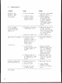
IV. TROUBLESHOOTING
Symptom
Cause
System is nonoperable; power
switch is not
illuminated
a. Loss of AC power
Circuit breaker
trips repeatedly;
short circuit LED
remains lit
a. Shorted or mis-wired
interconnect cable
b. Internal fuse is
blown; could be
caused by power
supply failure.
b. Defective remote unit
Remedy
a. Plug unit into dependable AC source
b. Replace fuse; if it
blows repeatedly,
bridge rectifier
or other component
probably shorted
inside power supply.
Have power supply
fixed.
a. Remove cables, one at
a time, from Main
Station until faulty
line is located. Check
for shorts between
Pins 1 and 2.
b. Check remote unit.
____________________________________________________________________________
Hum or buzz in system
a. Inductive pick-up
caused by close
proximity of Main or
Remote Station to
power lines or
transformers.
a. Relocate offending
unit.
c. 10 ohm chassis
ground resistor (R14)
in power supply is
open*
c. Check resistance
between chassis and
Pin 1 of connector,
make sure it's ten
ohms. If not,open
power supply and
replace resistor.
d. Move mic away from
"hum field" or use
carbon or electret
headset.
structions.
d. inductive pick-up
by headset mic; check
by switching mic on
and off
__________________________________________________________________________
Excessive background
noise pick-up by mic
a. distance from mic to
lips is too far
b. volume too high
c. too many mics "on"
in entire system
(continued)
18
a. Move away from mic
b. Lower headset/
speaker volume
c. Turn off all unused
mics
Symptom
Cause
Remedy
System Feedback
Acoustical
a. Check sidetone levels
b. Check termination
c. Volume too high at
one station
d. Two or more speaker
stations have mics
on simultaneously;
speak one at a time
(per channel)
* Power Supply's 10-ohm resistor is opened when the system ground
comes in contact with something "hot," with respect to the Main
Should this occur, we recommend you
Station Earth Ground.
carefully check the system ground and AC distribution in the
area. NOTE: THIS IS A POTENTIALLY DANGEROUS SITUATION; IF IT
OCCURS, A SHOCK HAZARD MAY OCCUR BETWEEN METAL BOOM OF HEADSET
AND GROUND.
19
V.
CS-210 SPECIFICATIONS
AMPLIFIER DESIGN:
IC amplifiers includi ng solid-state switching and signal ling circuits.
Current-limited and short-circuit protected.
MICROPHONE PRE-AMP:
Low impedance (Ik ohm) for
Input:
200 ohm nominal dynamic elements
-55 dBv nominal,
Input Level:
-10 dBv max. before clipping*
+37 dB
Nominal Gain:
Freq. Response: 250 Hz-12kHz with a
contoured response to
enhance voice intelligibility
Gain Adjust:
+5 dB
Limiter Range:
25 dB
HEADPHONE AMPLIFIER:
Drives any load of at least 150
ohms to full output (+18 dBv)
<0.2% THD at 1kHz
Distortion:
Gain from intercom line: +37 dB max
Frequency Response: 150-18kHz +2 dB
PROGRAM AMPLIFIER:
Gain, input to intercom line, max.:
+49 dB (mic), -1 dB (line)(the gain
to headset output is a max. of
37 dB more than to intercom line)
150-18k Hz
Frequency Response:
3.6k balanced
I nput Impedance:
(mic), 300k ohms balanced (line)
Input Level: -75 dBv nominal (mic),
-15 dBv nominal (line),
max. before clipping;
Volume full on, -52 dBv (mic),
+3 dBv (line)
POWER SUPPLY:
30 VDC, regulated
Output Voltage:
i amp max.
Output Current:
>50 dB
Channel Separation:
>55 dB
Signal-to-Noise:
OPERATING CONDITIONS
Channel Monitoring:
Push-button-selectable A, B, or both
Call Circuitry: Receives a signal from remote stations whether or not channel
is monitored.
The Call button sends a signal only on channel(s) being monitored.
Capacity: Will support up to 60 headset stations or 12 speaker stations.
System Impedance: 200 ohms, internally terminated (jumper-removeable)
System Level: -18 dBv nominal; 0 db before clipping*
Signallingi: Call Light Sensitivity--4 VDC max.; Call Voltage--11 VDC min.
Stage Announce: balanced, line-level (0 dBv) transformer-isolated 600 ohm output from mic pre-amp
CONNECTORS
Headset:
(2) XLR 4-pin male
Channel Outputs: (6) XLR 3-pin male
Stage Announce:
(1) XLR 3-pin male
Program Input: (1) XLR 3-pin female
Ext. Speaker:
1/4" mono phone jack
POWER REQUIREMENTS
105-125 or 210-250 VAC; 50-60 Hz,
DIMENSIONS
3-1/2" H x
switch-selectable from rear panel; 60 watts max.
9-11/16" W x 11-11/16" D (front to back)
(89 mm x 254mm x 305mm)
ENVIRONMENTAL TOLERANCE
0-50 degrees C (32-122 degrees F)
* 0 dBv is referenced to 0.775 volts RMS.
20
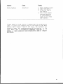
CS-210 MAIN STATION:
PARTS LISTING
Part number
Description
180000
210013
210121
210122
240010
240014
240015
240032
250219
250220
390010
510002
510006
510012
510053
510065
510066
520025
520027
520029
610000
640000
710154
Filter Choke
Headset Connector, 4-pin XLR male
Connector Panel Mount, male
Connector Panel Mount, female
Rubber foot, 1/2" square
Volume knob, 3/4" wide
Volume knob, 1/2"t wide
Carry Strap, 8" brown w/ hardware
CS-210 chassis
CS-210 chassis cover
LED, red, panel-mount
Power Switch, rocker, illumin.
Toggle Switch, mini
Pushbutton, momentary
Slide Switch (line voltage select)
Slide Switch (program assign)
Slide Switch (mic on/off)
Fuse, .5 amp slow-blow
Fuseholder
Circuit breaker, .9 amp
Power cord, 3-conductor
Strain relief for power cord
CS-210 printed circuit board assy.
810009
820020
CS-210 Operation & Service manual
(optional) CS-210 Rack-Mount Kit
qty
I
2
7
1
4
1
1
1
1
1
1
1
1
2
1
I
1
1
1
1
1
1
1
21
--=-i--==X11 - ----Z.Z ;I -
-