1
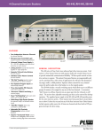
PS-1 0/PS-1 OK
Power Supply
INSTRUCTION
and
SERVICE MANUAL
Cv)Clear-Conm®
Intercom systems
ALSO INCLUDES:
RS-100A Belt-Pack
Operating Instructions
*
11111 7th Street * San Francisco, California 94107 * 415-861-6666
CLEAR-COM 810011
10/10K/9-83 Rev. A
PS-10/PS-10K
Operating Instructions
Table of Content:
The Clear-Com Concept ..................... 1
Introduction to the PS-10 ................ 1
2
Interfacing with Other Systems .-5
III System Interconnection.
6
220 VAC Operation.
8..........8
IV Trouble-Shooting ...............
9
Warranty & Maintenance.
V
9
VI Specifications.
11
.
RS-LOOA BELT-PACK OPERATION MANUAL .
I
II
Illustrations
Front View/Rear View of PS-10
Dual Power Supply Interconnection.
.
.
Daisy Chain System
.
.
Loop-Through System
..
.
PS-10 Schematic
.
.
.
3
7
7
7
i
an
I. The Clear-Com Concept
Clear-Com is a closed-circuit intercom system that provides highly
intelligible, two-way communications
ability in high- and low-noise environments.
A basic system consists of a Power Supply or Main
Station connected to various Remote
Headset or Speaker Stations.
Clear-Com manufactures a wide range
of portable, rackmount, and custommount intercom stations.
All are
compatible and will interface with
a variety of other communications
systems.
Most Clear-Com intercoms interconnect with two-conductor shielded
microphone cable that is input to
the stations with 3-pin, XLR audio
connectors.
One wire in the cable
carries DC power (28-32 volts) from
the Power Supply or Main Station to
the Remote Stations, and the other
wire carries the audio signal. The
shield acts as common ground. Only
one termination is needed throughout the intercom system, and that's
accomplished by one of the Power
Supplies or Main Stations within the system.
Clear-Com is a distributed amplifier system, which means each Main
Station and Remote Station contains
its own mic preamplifier
power
amplifier (for headset or speaker),
and signalling circuitry.
Clear-Com intercoms feature "Automatic
Headset Detection;"
this
shuts off any station's mic preamplifier when the mic or headset is
disconnected- Therefore an unused,
on-line mic never adds background
noise to the line.
Low-impedance
mic input lines (200 ohms) make
Clear-Com channels virtually immune
to RF and dimmer noise.
Remote
Stations bridge the intercom line
at a very high impedance and place
a minimum load on the line.
Audio
level remains constant, and never
fluctuates when stations leave or
join the system.
The 28-32 volts DC provided by
the
Power Supply or Main Station enable
the Remote Stations to operate with
minimal current (headset stations,
10 ma quiescent; speaker stations,
20 ma quiescent) while generating
loud listen levels
(greater than
110 dB SPL).
The higher voltage
and low current keep voltage losses
to an absolute minimum in long
lines. If the voltage drops due to
the addition of extensive cabling
or many more stations, Clear-Com
equipment will continue operating
normally with less than 12 volts
available.
II. INTRODUCTION TO THE PS-10 POWER SUPPLY
The PS-10 is a single-channel power
supply available as a portable (PS10) or a 3-1/2" rack-mount unit
(PS-10K). Designed to operate with
all Clear-Com single-channel Remote
Stations, the PS-10 is especially
suited for use with smaller intercon systems. It supplies the power
(28 volts DC at 0.6 amps) to support a maximum of 15 headset stations or 5 speaker stations.
The PS-10 terminates the audio line
for the entire system;
its rear
panel provides a termination on/off
switch.
The PS-10 features a circuit breaker that protects the power supply
from damage caused by faulty or
shorted cable. If a short occurs
the circuit breaker on the PS-10
front panel will pop out, and the
red LED labelled "short" will glow.
Once the short is removed, pressing
the circuit-breaker button automa-
=I.
Introduction to the PS-10 Power Supply, continued
tically re-sets the system.
The PS-10 front panel provides an
XLR-type,
3-pin male connector for
convenient output to an intercom at
INTERFACING WITH OTHER SYSTEMS
The Clear-Com AC-1O "Adapt-A-Com"
is
a
universal
adapter
that
interfaces the Clear-Com intercom
system with another intercom or
communications link/device.
The
AC-10 guarantees compatibility with
virtually any in-house intercom you
may already have, be it a 2-, 3-,
or 4-wire system.
Because it will simulate a carbon
mic, the AC-1O can be plugged into
2
the power supply's location (e.g.,
stage manager's or director's position).
In addition, the rear panel
provides three connectors for output to the Remote Stations.
the headset jack of a
control unit-
TV
camera
Our AC-10H operates with telephone
systems and provides a holding coil
feature. This facilitates on-line
communication via standard telephones and aids in direct communication between the director and
remote intercom users via 2- or 4wire dedicated TELCO pairs.
FRONT VIEW OF THE PS-10
SHORT LIGHT
v
POWER ON/OFF SWITCH
/
OUT PUT CONNECTOR
SHORT RESET BUTTON
REAR VIEW OF THE PS-10
-OUT PUT CONNECTORS
TERMINATION
ON/OFF
W11
5v
POWER CORD
0
3
7
I
m
SYSTEM INTERCONNECTION
The PS-1OK mounts in a standard 19"
rack, while the portable PS-10 can
go anywhere.
Cable is run from the
3-pin connectors to all headset and
speaker stations.
Allow at least
three inches behind the unit for
cables extending from the
rear
panel, and avoid sharp bends in the
cabling.
The PS-10 provides four XLR-type 3pin connectors for intercom output.
All four are internally connected
in parallel.
CHOOSING INTERCONNECT CABLE
When choosing interconnect cable,
keep the following considerations
in mind:
1) DC resistance affects crosstalkIn permanent installations, do
not use wire smaller than 20
gauge,
stranded (except
runs
shorter than 100 feet).
Keep
the total resistance under 100
ohms.
2) The capacitance of the cable
affects the system's frequency
response and sidetone stability.
Total capacitance should not be
greater
than .25 microfarads
(capacitance between conductor
and shield; equivalent to an
intercom system containing 5000
feet of 50 pF/foot of cable).
3) Clear-Com intercoms operate with
cable that has no more than 35
pF from conductor to conductor,
and no more than 70 pF from
conductor to shield.
PORTABLE SYSTEM CABLE
Typical cable for connecting the
PS-10 to portable Remote Stations
is rubber-Jacketed, two-conductor,
shielded mic cable. We suggest you
use BELDEN 8413 (24 gauge, stranded) for connections totalling 500
feet or less, and BELDEN 8412 (20
gauge, stranded)
for connections
that reach tip to 5000 feet.
If you don't use Belden cable, use
an equivalent type with similar
wire gauge and capacitance.
Cable
(especially in longer runs) should
have low DC resistance (less than
15 ohms per 1000 feet; large diameter
conductors)
and low interconductor capacitance (less than or
equal to 55 pF/foot of cable, capacitance
between
conductor
and
shield).
Most Remote Stations (such as beltpacks) each have a pair of
input
and output connectors; when installing a system with these, you can
"daisy-chain" many stations along
one interconnect path.
Alternately, you can try Clear-Com's Quadropuss Splitter (one line in,
three
lines out). These methods simplify
installation and lessen the overall
length of cable in the system.
PERMANENT INSTALLATION CABLE
We recommend you use vinyl-insulated and jacketed cable for connections to wall-mounted or custommount intercoms;
it costs less and
is easier to pull through conduit
than the rubber-insulated cable.
Use low capacitance cable.
We
suggest BELDEN 8762
(20
gauge,
stranded) for applications up to
500 feet,
and BELDEN 8760
(18
gauge, stranded) for up to 5000
feet.
Again, if you don't use Belden
cable, use an equivalent type with
similar wire gauge and capacitance.
If conduit is available when installing mounted Remote Stations,
run interconnect cable through the
conduit to each installed intercom.
NOTE:
Chassis ground and signal
ground
(Pin 1 on 3-pin intercom
connectors) are NOT the same point.
NEVER connect the chassis and Pin 1
5
III
System Interconnection, continued
together. The chassis is insulated
from the signal ground with a capacitor (.01 microfarad, 1.4 kv).
This eliminates the hum and potential shock hazard that can arise if
intercom stations are at a different ground potential-
If the conduit already has Class II
wiring, you can use that,
it's shielded or not.
whether
If you're NOT using conduit, and
the intercoms don't share a common
it is good engineering
ground,
additional
to run an
practice
ground wire to tie together all the
chassis (this decreases susceptibility to electrical noise fields)-
SYSTEM SET-UP PROCEDURE:
1) Route cable from the rear panel connectors on the PS-10 to the Remote StaThe pin-out
Use any or all of the connectors on the power supply.
tions.
assignment on all Clear-Com intercom connectors is:
Pin 1-- COMMON
Pin 2-- +VDC
Pin 3-- INTERCOM AUDIO
Route cable away from heavy AC power sources,
electric motors.
In permanent installations,
codes.
such as lighting
panels
or
install cable in accordance with local building
2) Set the termination on/off switch on the PS-10 rear panel to the "on"
tion if the unit is the only power source in the system.
posi-
the
power
3) Plug in the PS-10 power cord to a source of 115 VAC.
switch (which lights up when activated).
4) Set the individual
Stations.
Turn
on
volume controls for ideal listen levels at
the
Remote
220 VAC OPERATION
1) To operate from 220 VAC, unscrew the rubber feet (or screws) from the bottom
of the PS-10, remove the two screws that secure the handle to the top of the
unit, then remove the cover.
2) Refer to the system schematic included in this manual, and re-wire the transformer as shown, using the appropriate power cord.
3) Remove the internal fuse and replace it with a 1/8a, slo-blo fuse.
4) Replace cover, handle, and feet/bottom screws.
6
0
System Interconnection, continued
MULTIPLE POWER SOURCES
Power Supplies and Main Stations
can be paralleled together in the
intercom system.
A second power
source doubles the system capacity
and acts as a back-up if the other
source goes down.
The
diagram below illustrates
interconnection
of two power
the
sup-
plies, which may be installed at
the same end of the intercom line
or at opposite ends. Note that the
termination should be "on" in only
ONE power source, and should be
"off" in the other(s)TmmInW]..OFF
\i52_
com
T.nnlnhtloON
PS-10
DAISYCHAIN
This works fine, but if the cable
were cut anywhere along the signal
path, all stations would go down.
An alternative configuration (shown
below) solves this problem. Using
two connectors at the beginning and
end of one cable establishes a
loop-through that prevents system
failure should a cut in the line
occur.
3111
PS-10
LOOP-THROUGH SET-UP
A typical configuration might look
like this:
A.1.
f3
|iS-10
; ~~~~~~~
~~
..
30
corn
DUAL POWER SUPPLY INTERCONNECTION
LOOP-THROUGH
0
7
U.g
TROUBLE-SHOOTING THE PS-IO
SYMPTOM
CAUSE
REMEDY
System is totally dead,
light in power switch
doesn't come on
a. loss of AC power
a. plug the power supply
into a good outlet
b. replace fuse*
b. internal fuse has
blown
Circuit breaker trips
repeatedly, or "short"
LED remains lit
a. shorted or mis-wired
interconnect cable
b. defective remote
station
remove cables from the
power supply, one at a
time, until the faulty
line is isolated. Check
for shorts between Pins I
and 2 on XLR-type 3-pin
intercom connectors.
Hum or buzz in system
a. inductive pick-up
caused by close proximity of power supply
or remote station to
power lines of transformers.
a. re-locate offending
station
b. ground loop caused
by improper grounding
of system (see installation procedure)
b. reverse power cord;
lift ground
c. 10 ohm chassis ground
resistor (RI in schematic) in power supply is
open**
c. measure resistance between chassis and Pin I
of intercom connectors.
It should be 10 ohms. If
not, open up the supply,
check and/or replace the
resistor.
the internal fuse blows repeatedly, there's a good chance that the bridge
*if
Bring the
rectifier or other component has shorted inside the power supply.
Clear-Com
contact
or
repair
for
station to your dealer
**IMPORTANT: This is caused by the system ground coming in contact with someShould this occur,
thing "hot" with respect the the power supply earth ground.
AC distribution
and
ground
system
of
the
check
we recommend you make a careful
OCCURS, A SHOCK
IT
IF
SITUATION;
HAZARDOUS
POTENTIALLY
THIS IS A
in your area.
GROUND.
AND
HEADSETS
OF
BOOMS
METAL
HAZARD COULD OCCUR BETWEEN THE
8
.V
WARRANTY AND MAINTENANCE
Your Clear-Com System contains modular, solid-state equipment that
allows system expansion and field
serviceability. Efficient ventilation is inherent in chassis design;
the PS-dO can withstand an ambient
temperature of 50 degrees C (122
packaging
F).
Rugged
degrees
guards against abuse; the chassis
are 16 gauge aluminum or stainless
with double-sided, glass
steel,
Our conepoxy plug-in PC boards.
circuitry
servatively-engineered
assures the longest component life.
We shield heavily against hum, RF
and solid-state dimmer
pick-up,
noise.
Before shipping,
we test each unit
it
individually to ensure that
meets or exceeds all specifications. All units are guaranteed by
Clear-Com against defects in materials and workmanship for one year
following date of purchase (90 days
for headsets; see the warranty card
enclosed with each unit).
Our Engineering, Service, and Sales
Departments will gladly give you
technical advice and assistance.
If you have any questions regarding
operation, modifications, or applications of your intercom system,
call us between 8:30 and 5 pm
(Pacific Standard Time) at 415-8616666.
VI PS-10/PS-1OK SPECIFICATIONS
Power Supply:
Output Voltage:
Output Current:
28 volts DC, circuit-breaker protected,
unregulated
0.6 amps maximum
Operating Conditions:
Capacity:
will support up to 15 headset stations
or 5 speaker stations
System Impedance:
200 ohms nominal
System Level:
-15 dB nominal; 0 dB before clipping
Connectors:
Output:
3-pin, XLR-type, male
four connectors in parallel
POWER REQUIREMENTS:
115/230 VAC, 50-60 Hz, 40 watts max
DIM4ENSIONS:
PS-10-- 6.75"w x 7.25" x 3.38"h
PS-10K-- 19"w x 7.25 x 3.5" h
weight-- 4 lbs, 8 oz.
ENVIRONMENTAL:
0-50 degrees Celsius
(32-122 degrees Fahrenheit)
t;~~~~~~~~~C
zip
:
l
-are
:~~O)Z
----
Z 3s
ln
-- p
¢ 8-uT~trn
w
.711 CT-r'--o>
-
i
(
SP
ant
r~~~e~~t
~~~~~~~~~~~~~~~~~~~~~~~~~10
m(
c
3
s m>
O