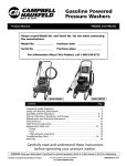
1
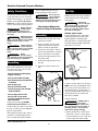
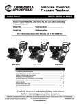
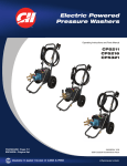
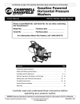
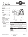
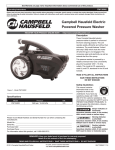
TM
BUILT TO LAST
Gasoline Powered
Pressure Washers
Refer to Product Manual for Detailed Safety Instructions
Assembly Instructions and
Replacement Parts Manual
PW2120, PW2318,
PW2408, and PW2418
Please read and save these instructions. Read carefully before attempting to assemble, install, operate or
maintain the product described. Protect yourself and others by observing all safety information. Failure to
comply with instructions could result in personal injury and/or property damage! Retain instructions for
future reference.
Please record Model No. and Serial No. for use when contacting
the manufacturer:
Model No. ______________
Purchase date ____________________
Serial No. ______________
Purchase place ____________________
For Information About This Product,
call 1-800-330-0712
Contents
Page
Safety Guidelines . . . . . . . . . . . . . . . . . . . . . . . . . . . . . . . . . . . . . . . . . . . . . . . . . . 2
Assembly. . . . . . . . . . . . . . . . . . . . . . . . . . . . . . . . . . . . . . . . . . . . . . . . . . . . . . . . . 2
Start-up . . . . . . . . . . . . . . . . . . . . . . . . . . . . . . . . . . . . . . . . . . . . . . . . . . . . . . . . 2-3
Shutdown . . . . . . . . . . . . . . . . . . . . . . . . . . . . . . . . . . . . . . . . . . . . . . . . . . . . . . . . 3
Replacement Parts Ordering Instructions . . . . . . . . . . . . . . . . . . . . . . . . . . . . . . 4-5
Maintenance . . . . . . . . . . . . . . . . . . . . . . . . . . . . . . . . . . . . . . . . . . . . . . . . . . . . . 6
Service Record . . . . . . . . . . . . . . . . . . . . . . . . . . . . . . . . . . . . . . . . . . . . . . . . . . . . 6
Notes . . . . . . . . . . . . . . . . . . . . . . . . . . . . . . . . . . . . . . . . . . . . . . . . . . . . . . . . . . 7-8
© 2000 Campbell Hausfeld
For parts, product & service information
visit www.campbellhausfeld.com
IN457900AV 4/00
Gasoline Powered Pressure Washers
Safety Guidelines
sure to tighten fittings, bolts, etc.,
before putting unit into service.
Start Up
This manual contains information that
is very important to know and understand. This information is provided for
SAFETY and to PREVENT EQUIPMENT
PROBLEMS. To help recognize this information, observe the following symbols.
Do not operate
unit if damaged
during shipping, handling or use.
Damage could result in bursting and
cause injury or property damage.
ALWAYS use this start up procedure to
ensure that the unit is started safely
and properly.
Danger indicates
!
an imminently
hazardous situation which, if not
avoided, WILL result in death or serious injury.
DANGER
Warning indicates
a potentially hazardous situation which, if not avoided,
COULD result in death or serious
injury.
! WARNING
Caution indicates
!
a potentially hazardous situation which, if not avoided,
MAY result in minor or moderate
injury.
CAUTION
Notice
indicates important information, that if not followed,
may cause damage to equipment.
!
NOTICE
Unpacking
Remove the equipment and all parts
from the carton. The carton should
contain the following:
! WARNING
If water has
frozen in the pressure washer, thaw in a warm room
before starting. DO NOT pour hot
water on or into the pump; internal
parts will be damaged.
!
See Product Manual for
General Safety Information
Assembly
1. Slide handle over legs and secure
with bolts provided.
2. Insert removable spray tips and
rubber grommets into holes provided on frame (if applicable).
CAUTION
TRIGGER SAFETY LATCH
In the engaged position, the trigger
safety latch prevents the gun from
being triggered accidentally. Push
latch fully down to engage (See Figure
2). Always engage trigger safety latch
when unit is not in use.
3. Connect the clear plastic chemical
suction tube with filter to chemical
injector hose barb on the pump.
Engaged
4. Connect the high-pressure hose to
the pump outlet.
5. Connect the high-pressure hose to
the gun.
6. Attach lance with nozzle to the
gun.
Disengaged
Pump outlet
One (1) Pressure washer (pump,
engine, cart base)
One (1) Cart handle Assembly
Figure 2 - Trigger Lock
One (1) Basket (not included with
all models)
1. Check oil levels. Add oil as necessary.
One (1) Spray gun
One (1) Lance with nozzle
Five (5) Spray tips (not included
with all models)
Chemical
injector
hose barb
One (1) High pressure hose
One (1) Pack of nuts, bolts,
manuals and Chemical Suction
Tube with Filter
If any parts are missing, DO NOT
return unit to the retailer. Know
model number (located on serial number tag on frame) and call 1-800-3300712 for replacement.
NOTE: Some units are equipped with a
low-oil sensor that shuts engine off if
oil level falls below a certain level. If
unit stops unexpectedly, check both oil
and fuel levels. Check oil level each
time unit is refueled.
2. Check fuel level.
Pump inlet
Figure 1 - Pump hook up
DO NOT refuel a
hot engine.
Refueling a hot engine could cause a
fire. Use only fresh, clean regular or
unleaded gasoline. Close the fuel
shutoff valve during refueling.
! WARNING
3. Attach garden hose to inlet side of
pump and connect to water supply.
Hose should have an I.D. of 5/8” and
not be longer than 50 ft. (15 M).
After unpacking the product, inspect
carefully for any damage that may
have occurred during transit. Make
www.campbellhausfeld.com
2
PW2120, PW2318, PW2408 and PW2418
Start Up (Continued)
Some local plumbing codes require
backflow prevention when connecting
to a fresh water supply. Install backflow preventer upstream from the
pump if necessary.
!
CAUTION
a. If inlet water pressure is over 100
psi (7 bar) a regulating water
valve must be installed at the garden hose connection.
b. Do not exceed 100¯ F (38¯ C) inlet
water temperature.
NOTE: The inlet water supply must
have a minimum flow rate of 5 gpm
(19 lpm).
4. Turn on the water supply.
Never run the unit
dry. BE SURE water
supply is completely turned on before
operating unit.
!
CAUTION
5. Trigger gun until water sprays from
tip indicating all air is purged from
system. Set trigger safety latch.
6. Open fuel shutoff valve (if unit is
equipped with valve). Be sure spark
plug ignition cable is pushed firmly
onto spark plug. On units equipped
with an ignition shutoff switch, put
switch in the “ON” position and put
throttle in the “RUN” position.
up in the high pressure hose. Go
back to step 7 and repeat until
engine starts.
Shutdown
1. Be sure all detergent is flushed
from system.
2. Turn off engine.
3. Turn off water supply.
4. After engine and water supply are
turned off, trigger the gun to
depressurize the system.
NEVER turn the
water supply off
before turning the engine off. Serious
damage could occur to the pump
and/or engine.
!
CAUTION
NEVER disconnect
the high pressure
discharge hose from the machine
while the system is pressurized. To
depressurize, turn engine off, turn
water supply off and squeeze gun
trigger 2-3 times.
! WARNING
5. After each use, wipe all surfaces of
the pressure washer with a clean,
damp cloth.
PRESSURE RELIEF
PROCEDURE
To reduce the risk of bodily injury
or property damage, always follow this procedure whenever
spraying is stopped, when work is
completed and before checking
or repairing any part of the system.
1. Engage the trigger safety
latch.
2. Turn unit off.
3. Remove ignition cable from
spark plug.
4. Shut off water supply.
5. Disengage trigger safety latch
and trigger gun to relieve
pressure.
6. Re-engage trigger safety latch.
7. Before overnight or long term
storage or transporting unit,
disconnect water supply and
turn off the fuel supply valve.
NOTE: A winterizing kit,
(PW104200AJ) is available for long
term storage.
7. Start engine.
If engine is cold, completely close
engine choke. Grasp starter rope,
brace one foot on chassis then pull
rope rapidly and firmly. Continue
holding rope as it returns. Pull and
return the rope until engine starts.
In cool weather, the choke may have
to be kept closed for 10 to 30 seconds to keep the engine running.
Otherwise, open choke as soon as
engine starts.
If engine is warm, leave choke open
or just partially closed. Start engine
then open choke completely.
Never let starter
rope return by
itself. This could jam the recoil system.
!
NOTICE
8. If engine does not start after 2-3
pulls, squeeze the gun trigger to
release the pressure that has built
www.campbellhausfeld.com
3
PW2120, PW2318, PW2408 and PW2418
Gasoline Powered Pressure Washer
For Replacement Parts, Call 1-800-330-0712
*** 6
7 (2)
8 (2)
9 (2)
1
2 (2)
3 (2)
4 (4)
22
5***
20
23
11 (right side)
12 (left side)
26 (2)
2 (2)
3 (2)
4 (4)
21
15 (2)
16 (2)
17 (2)
10
2 (1)
3 (1)
4 (2)
24
25
18 (2)
19 (2)
13
14 (2)
3 (2)
4 (4)
www.campbellhausfeld.com
4
PW2120, PW2318, PW2408 and PW2418
Replacement Parts List
Please provide following information:
- Model number
- Serial number (if any)
- Part description and number as shown in parts list
Ref.
No. Description
Address parts correspondence to:
The Campbell Group
Attn: Parts Department
100 Production Drive
Harrison, OH 45030 U.S.A.
PW2120
PW2318
PW2408
PW2418
Qty.
PM060020SJ
PM060020SJ
PM060020SJ
PM060020SJ
1
1
Handle/placard assembly
2
1/4-20 x 1.75 Hex head bolt
*
*
*
*
5
3
1/4-20 Nylock nut
*
*
*
*
7
4
Flatwasher, 1/4-20
*
*
*
*
14
5
Hose rack
PM223700AV
PM223700AV
PM223700AV
PM223700AV
1
6
Gun rack
PM033410AV
PM033410AV
PM033410AV
PM033410AV
1
7
10-24 x 1.75 Socket head cap screw
*
*
*
*
2
8
10-24 Nylock nut
*
*
*
*
2
9
Flatwasher, 10-24
*
*
*
*
2
10
Baseplate
PM223200AV
PM223200AV
PM223200AV
PM223200AV
1
11
Leg, right side
PM223610BH
PM223610BH
PM223610BH
PM223610BH
1
12
Leg, left side
PM223620BH
PM223620BH
PM223620BH
PM223620BH
1
13
Axle
PM224501BH
PM224501BH
PM224501BH
PM224501BH
1
14
1/4-20 x 2.0 Hex head bolt
*
*
*
2
15
Wheel
WA005100AV
WA005100AV
WA005100AV
WA005100AV
2
16
Hub cap
PM224400AV
PM224400AV
PM224400AV
PM224400AV
2
17
Push nut
MJ104700AV
MJ104700AV
MJ104700AV
MJ104700AV
2
18
Rubber bumper
AL062300AV
AL062300AV
AL062300AV
AL062300AV
2
19
1/4-20 x .75 Self tapping screw
*
*
*
2
20
Engine
PM004050AV
PM004100AV
PM226600AV
PM223000AV
1
21
Pump assembly**
PM223100SJ
PM223100SJ
PM223100SJ
PM223100SJ
1
22
Gun
PM005133AV
PM005133AV
PM005133AV
PM005133AV
1
23
Lance
PM035170AV
PM035170AV
PM035140AV
PM035140AV
1
24
Hose
PM012904AV
PM012904AV
PM012904AV
PM012904AV
1
25
Detergent tube and filter
PM013800AV
PM013800AV
PM013800AV
PM013800AV
1
26
1/4-20 x 1.50 Hex head bolt
*
*
*
2
*
*
*
*Item available at local hardware store
**See replacement parts list IN458000AV
***Components not included with handle/placard assembly (ref #1)
www.campbellhausfeld.com
5
Gasoline Powered Pressure Washer
Maintenance
Observe regular maintenance intervals to ensure maximum performance
and life from the pressure washer.
Refer to the schedule for recommended maintenance. If unit is operated
in dusty conditions, perform maintenance checks more often.
Maintenance Schedule
Maintenance Schedule
Action needed
Daily
Check water inlet screen and filter
Check engine and pump oil levels. Fill as necessary
Check gasoline level. Fill as necessary
After first 5 hours of
operation
Change engine break-in oil. Drain oil when warm
Use SAE30 or 10W-30 detergent oil
Every 25 hours of
operation
Clean and remove air cleaner filter (if applicable)
Wash with water and mild detergent. Dry thoroughly. Rub with oil and squeeze to distribute oil
Each 100 hours of
operation or every 3
months
Clean or replace paper air cleaner cartridge. Tap
gently to remove dirt
Change engine oil. Use SAE30 detergent oil
Each 500 hours of
operation or every 6
months (horizontal shaft
units only)
Change pump oil. Use SAE30 non-detergent oil
Service Record
Date
Maintenance performed
Replacement components required
www.campbellhausfeld.com
6
PW2120, PW2318, PW2408 and PW2418
Notes
www.campbellhausfeld.com
7
Gasoline Powered Pressure Washer
Notes
www.campbellhausfeld.com