1
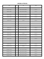
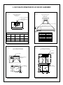
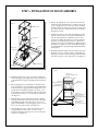
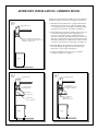
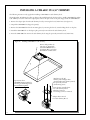
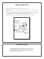
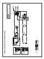
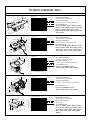
Installation Instructions
Chimney-Style Hoods
Indoor and Outdoor Applications
PLEASE READ ENTIRE INSTRUCTIONS BEFORE PROCEEDING.
INSTALLATION MUST COMPLY WITH ALL LOCAL CODES.
IMPORTANT:
INSTALLER:
OWNER:
SAFETY WARNING:
Save these instructions for the Local Electrical Inspector’s use.
Please leave these instructions with this unit for the owner.
Please retain these instructions for future reference.
Turn off power circuit at the service panel and lock out panel,
before wiring this unit.
IMPORTANT SAFETY INSTRUCTIONS
CAUTION - TO REDUCE THE RISK
OF FIRE, ELECTRIC SHOCK, OR
INJURY TO PERSONS, OBSERVE THE
FOLLOWING:
1. Use this unit only in the manner
intended by the manufacturer. If you
have any questions, contact the
manufacturer - Independent Inc.
(800-7-NEVADA)
2. Before servicing or cleaning the unit,
switch power off at service panel and
lock the service disconnecting means to
prevent power from being switched on
accidentally. When the service
disconnecting means cannot be locked,
attach a tag to the service panel to
indicate power has been switched off
for maintenance.
3. Install this Rangehood Only with
Remote Blower Models Rated
Maximum 12.8A or Integral Blowers
manufactured by Independent Inc.,
Models CFM 600, CFM600C,
CFM1200, CFM1200C.
C AU T I O N : F O R G E N E R A L
VENTILATION USE ONLY. DO NOT
USE TO EXHAUST HAZARDOUS OR
EXPLOSIVE MATERIALS OR VAPOR.
CAUTION - TO REDUCE THE RISK
OF A RANGE TOP GREASE FIRE:
1. Never leave surface units unattended
at high settings.
Boilovers cause smoking and greasy
spillovers that may ignite. Heat oils
slowly on low or medium settings.
2. Always turn hood ON when cooking at
high heat or when flambeing foods
(i.e. Crepes Suzette, Cherries Jubilee,
Peppercorn Beef Flambe.
3. Clean ventilating fans frequently.
Grease should not be allowed to
accumulate on fan or filter.
4. Always use cookware appropriate for the
size of the surface element.
CAUTION - TO REDUCE THE RISK
OF INJURY TO PERSONS, IN THE
EVENT OF A RANGE TOP GREASE
FIRE, OBSERVE THE FOLLOWING:
2. BE CAREFUL TO PREVENT BURNS.
If the flames do not go out immediately.
EVACUATE AND CALL THE FIRE
DEPARTMENT.
3. NEVER PICK UP A FLAMING PAN
- you may be burned.
4. DO NOT USE WATER, including wet
dish-cloths or towels - a violent steam
explosion will result.
5. Use an extinguisher ONLY if:
a.You know you have a class ABC
extinguisher, and you already know
how to operate it.
b. The fire is small and contained in
the area where it started.
c. The fire department is being called.
d.You can fight the fire with your back
to an exit.
1. SMOTHER FLAMES with a closefitting lid, cookie sheet, or other metal
tray, then turn off the gas burner or the
electric element.
1
IMPORTANT SAFETY INSTRUCTIONS FOR INSTALLATION
CAUTION TO REDUCE THE RISK OF FIRE,
ELECTRIC SHOCK, OR INJURY TO
P E R S O N S , O B S E RV E T H E
FOLLOWING:
C AU T I O N : F O R G E N E R A L
VENTILATION USE ONLY. DO NOT
USE TO EXHAUST HAZARDOUS OR
E X P LO S I V E M AT E R I A L S O R
VAPORS.
A. Installation work and electrical wiring
must be done by a qualified person
in accordance with all applicable
codes and standards, including firerated construction.
B. Sufficient air is needed for proper
combustion and exhausting of gases
through the flue (chimney) of fuel
burning equipment to prevent
backdrafting. Follow the heating
equipment manufacturer’s guidelines
and safety standards such as those
published by the National Fire
Protection Association (NFPA), and
the American Society for Heating,
Refrigeration and Air Conditioning
Engineers (ASHRAE), and the local
code authorities.
C. When cutting or drilling into a wall or
ceiling, do not damage electrical
wiring and other hidden utilities.
D. Ducted fans must always be vented to
the outdoors.
F. NEVER place a switch where it can
be reached from a tub or shower.
G. CAUTION - TO REDUCE THE
RISK OF FIRE, USE ONLY
METAL DUCTWORK.
H. Install this hood in accordance with
all requirements specified by the
manufacturer of your cooktop/range.
I. Install this hood using required
clearance from cooking surface to
combustible material specified in
cooktop installation instructions.
E. If this unit is to be installed over a
tub or shower, it must be marked as
appropriate for the application and
be connected to a GFCI (Ground
Fault Circuit Interrupter) - protected
branch circuit.
READ AND SAVE THESE INSTRUCTIONS
INSTALLATION PRECAUTIONS
The high degree of craftsmanship in the construction and finish
of your hood requires careful handling to ensure proper
installation.
• Do not remove your hood from its crate until you are ready
to hang it.
• Do not store your hood anywhere other than within the box.
If it is necessary to remove your hood from the box, arrange
it on a blanket or padded area that will protect your
hood from scratches or indentations.
• Do not lift the hood by its utensil rail. Place your fingers under
the lower reveal of the hood. Grasp firmly and lift.
• Cotton gloves are preferable. They will protect the surface
from fine scratches and eliminate fingerprints.
2
• Remove all rings, watches, belt buckles, and jackets
(snaps-zippers) to prevent scratch marks.
• Do not remove the plastic from your hood until the installation
process is complete. It will be necessary to remove only
a small portion on the back-side of a wall mounted hood
in order to position in place.
• Located within the hood cavity (behind the baffle filter)
are component parts and halogen bulbs.
MODEL OPTIONS
Model
Lights
Fans
Material
CHIMNEY - CHIM 30"
2
CFM600C
Stainless Steel
CHIMNEY - CHIM 36"
2
CFM600C, CFM1200C, CFMR1400
Stainless Steel
CHIMNEY - CHIM 42"
2
CFM600C, CFM1200C, CFMR1400
Stainless Steel
CHIMNEY - CHIM 48"
3
CFM600C, CFM1200C, CFMR1400
Stainless Steel
CHIMNEY - CHIM 54"
3
CFM600C, CFM1200C, CFMR1400
Stainless Steel
CHIMNEY - CHIM 60"
3
CFM600C, CFM1200C, CFMR1400
Stainless Steel
CHIMNEY - CHIM 66"
3
CFM600C, CFM1200C, CFMR1400
Stainless Steel
LARAMIE - LARA 30"
2
CFM600C
Stainless Steel
LARAMIE - LARA 36"
2
CFM600C, CFM1200C, CFMR1400
Stainless Steel
LARAMIE - LARA 42"
2
CFM600C, CFM1200C, CFMR1400
Stainless Steel
LARAMIE - LARA 48"
3
CFM600C, CFM1200C, CFMR1400
Stainless Steel
LARAMIE - LARA 54"
3
CFM600C, CFM1200C, CFMR1400
Stainless Steel
LARAMIE - LARA 60"
3
CFM600C, CFM1200C, CFMR1400
Stainless Steel
LARAMIE - LARA 66"
3
CFM600C, CFM1200C, CFMR1400
Stainless Steel
LAREDO - LARE 30"
2
CFM600C
Stainless Steel
LAREDO - LARE 36"
2
CFM600C, CFM1200C, CFMR1400
Stainless Steel
LAREDO - LARE 42"
2
CFM600C, CFM1200C, CFMR1400
Stainless Steel
LAREDO - LARE 48"
3
CFM600C, CFM1200C, CFMR1400
Stainless Steel
LAREDO - LARE 54"
3
CFM600C, CFM1200C, CFMR1400
Stainless Steel
LAREDO - LARE 60"
3
CFM600C, CFM1200C, CFMR1400
Stainless Steel
LAREDO - LARE 66"
3
CFM600C, CFM1200C, CFMR1400
Stainless Steel
WRANGLER - WRAN 36"
2
CFM600C
Stainless Steel
WRANGLER - WRAN 42"
2
CFM600C, CFM1200C, CFMR1400
Stainless Steel
WRANGLER - WRAN 48"
3
CFM600C, CFM1200C, CFMR1400
Stainless Steel
WRANGLER - WRAN 54"
3
CFM600C, CFM1200C, CFMR1400
Stainless Steel
WRANGLER - WRAN 60"
3
CFM600C, CFM1200C, CFMR1400
Stainless Steel
WRANGLER - WRAN 66"
3
CFM600C, CFM1200C, CFMR1400
Stainless Steel
3
INSTALLATION PLANNING
CHECK THE INSTALLATION LOCATION
•
If your installation has been roughed-in (including ductwork and wiring), be certain
there is nothing in the way of the mounting, pipes, other wiring etc.
•
If the installation has not been roughed in, check what is needed to create the framing
and mounting hardware (allthreads, nuts, etc.). Be sure the location will not interfere
with wiring, other utilities, or structural considerations.
CHOOSE THE INSTALLATION METHOD
•
There are several different methods available to mount the hood: the Unistrut, Angle
Iron, Frame In, Wall Mount, Island Mount and Rough-In Plate Mount, which can
be used for both indoor and outdoor. Please check the model options for the suggested
methods of your installation. Each hood type and site requirements are presented as
follows.
•
Please read the instructions in their entirety prior to installing the hood.
INSTALLATION QUESTIONS? PLEASE DIAL:
1-800-7-NEVADA
THE CHIMNEY HOOD COMES WITH AN INSTALLATION PACKAGE
WHICH INCLUDES THE FOLLOWING ITEMS
1. Ten (10) 10/24 Nuts
2. Ten (10) #10 Self Tapping Screws 2" Length
3. Ten (1) Knob
4. One (1) 10" Transition W/Damper, 36"-66" Hood (Mounted Upside Down Inside Hood) or
one (1) 8" Transition W/Damper, 30" Hood (Mounted Upside Down Inside Hood)
The Chimney Hood includes a standard “DuctCover” at a pre-specified height supplied by the
customer as part of the purchased package (shipped separately). The choice being a 12", 18" or
24" tall unit. Included with the “DuctCover” is the following hardware.
1. Eight (8) 12/24 Self Tapping Screws 7/8" Length
2. Four (4) 5/16" X 1" Bolts
STEP 1. DUCTING CONNECTION
4
1. For in-hood fans, CFM1200C, use 10" round ducting
from the provided transition.
3. For remote fans, use 10" round ducting from the
provided transition to the remote fan.
2. For in-hood CFM600C fans, use 8" round ducting
from the provided transition.
4. Ducting should be as short and straight as possible
for best fan performance. SEAL ALL JOINTS WITH
DUCT TAPE.
2. ROUGH-IN DIMENSIONS OF HOOD ASSEMBLY
Figure 3.
Figure 4.
Electrical and Ductwork
Rough-In location
Top View
Electrical and Ductwork
Rough-In location
Front View
10" Transition with Damper
(36-66" Hood)
8" Transition with Damper
(30" Hood)
CL
6"
C
B
Electrical Knockout Location
(Rear Electrical Rough-In Location)
A
18"
9-1/4"
B
A
Electrical Knockout Location (Rear Supply)
Electrical Rough-in Location (Top supply)
Hood
Size “A”
“B” with
Ductcover
“C” with
Ductcover
“B” without
Ductcover
“C” without
Ductcover
30" Hood
4"
10"
4.5"
10.5"
36"-54"Hood
7"
10"
7.5"
10.5"
60"-66" Hood
10"
10"
10.5"
10.5"
Figure 11.
36"-66" Chimney Hood includes
10"Round Transition with Damper
Knockout Offset
B
8-1/4"
8-1/4"
9-3/4"
11-1/4"
12-3/4"
12-3/4"
14-1/4"
Figure 15.
Hood Length
A
30"
36"
42"
48"
54"
60"
66"
30" Chimney Hood includes
8" Round Transition with Damper
1 1/2" Crimp
Backdraft
Damper
1-1/2" Crimp
1-7/8"
1-7/8"
1-3/4"
Backdraft Damper
Installed
11-1/8"
7-1/2"
1-3/4"
11-3/16"
7-1/2"
3/8"
1/2"
11-1/8"
10" Round
is on Centerline
10"
7-3/4"
1/8"
3/8"
8-3/4"
7-3/4"
1/4"
8" Round
is on Centerline
8"
1/8"
7-3/4"
1/2"
5
STEP 3. INSTALLATION OF HOOD ASSEMBLY
Figure 1.
Duct Cover
Transition
Plate
Drill & Screw
Into Structure
Chimney
Hood
Top Electrical
Knockout
Rear Electrical
Knockout
1. Position the Chimney hood on its back and locate the
transition inside the Chimney hood; remove the (4) #8
x 1/2" self tapping screws at the top of the hood which
hold the transition to the hood (save these screws for later
use), then remove the transition from the hood interior
through the bottom.
2. Install the transition to the duct work making sure the
bottom of the transition is centered and flush with the
bottom of the DuctCover. Check the position of the
transition by sliding the DuctCover over the mounted
transition, and verify that the transition is flush, and
centered to the bottom of the DuctCover. When transition
installation is complete, be sure to check that the damper
is not hindered from opening if using mechanical fasteners.
(See Figure 5.)
3. If the Electrical feed extends from the ceiling, remove the
knockout at the top of the hood prior to installing the
DuctCover, in order to facilitate feeding the Romex down
into the hood cavity to the electrical box. (See Figure 2.)
CFM1200C Blower
Figure 2.
4. Install the DuctCover to the top of the hood using the
12/24 self tapping 7/8" length screws. Also bolt the hood
to the DuctCover using the supplied stainless steel 5/16”
bolts.
5. Before hanging the hood, drill holes in the back of the
hood, if necessary, to line up with the structural members
in the wall. Also, be prepared when hanging the hood to
feed the electrical either through the top down, or use
the knockout provided in the back. You may drill a hole
in the back, if necessary, to accommodate the electrical.
(See Figure 2.)
6. Slide the Hood up the wall with the transition sliding
inside the DuctCover, then secure the hood to the back
wall (drilling through the back of the hood to locate
studs). Use the #10 x 2" long self-tapping screws to secure
the hood to the wall structure. (See Figure 6.)
7. Once the Hood is secure, attach the transition to the
rectangular plate at the junction of the hood and
DuctCover with the screws that were removed from the
transition. (See Figure 6.)
6
Option #1
Electrical Supply From
Ceiling.
Route to Hood J-Box.
Option #1
Remove Knockout &
Install Customer
Supplied Bushing Typ.
Optional
Duct Cover
Option #2
Remove Knockout &
Install Customer
Supplied Bushing Typ.
Option #2
Electrical Supply
From Rear.
Route to Hood J-box.
Figure 5.
Supply Ductwork
Verify that damper opens
unobstructed if using
mechanical fastners that attach
transition to ductwork.
10" Transition; position exhaust
ductwork so bottom of transition is
flush and centered with the bottom
of the duct cover.
8. Electrician may complete electrical connection to Hood
making the connection at the box inside the hood. (120
volt) See Figure (2) If using a remote fan please see
section “Wiring a Remote Fan”. (See Page 11.)
9. If using an internal CFM-1200C or CFM-600C fan
you will slide the fan mount over the studs at the
junction of the hood and DuctCover and use the 10/24
nuts supplied to fasten the fan to the hood.
(See Figure 10.)
IMPORTANT! If the Chimney hood is a 30" model please
see the instructions for mounting a CFM-600C page 10.
10. Plug the electrical “Y” pigtail into each of the fans and the
other single end into the hood Molex connector.
(See Figure 10.)
Range
Figure 7.
Supply Ductwork
Attach DuctCover to back wall
and to ceiling by drilling and
fastening with screws.
Figure 6.
Supply Ductwork
Attach Transistion to
Rectangular Plate.
Install Hood & Duct Cover
as One Unit over Transition.
Attach Hood to Structure
by drilling and fastening with
screws.
Range
Range
7
ALTERNATE INSTALLATION: CHIMNEY HOOD
Under certain circumstances the installer may opt for a different
installation sequence. The alternate sequence is listed below.
Figure 8.
Alternate
Install
Supply Ductwork
Transition; Position Exhaust Ductwork
so Bottom of Transition is Flush & Centered
with Bottom of Duct Cover.
1. Drill holes in back of DuctCover to align with structural
members; fasten DuctCover to wall using supplied #10
x 2" self tapping screws; attach duct cover through ceiling
opening in top of structure, if available. (See Figure 7.)
2. Install Transition to ductwork, assuring transition bottom
is centered and flush with bottom of DuctCover (in
most cases you will not be able to mechanically fasten
transition to ductwork. If mechanical fasteners are used, use
duct tape to hold transition in place until hood is mounted.
This may be followed by a small amount of silicone at the
connection of the transition to ductwork). (See Figure 8.)
3. Install the Hood to the DuctCover. Fasten the Hood to
back wall (drilling through the back of the Hood and
DuctCover to locate studs). (See Figure 9.)
4. Continue installation with sequence #7 of standard
installation instructions, on page 6
Range
Figure 9.
Alternate
Install
Supply Ductwork
Figure 10.
Alternate
Install
Supply Ductwork
Attach Fan to
Rectangular Plate Using
Supplied 10-24 Nuts.
Screw Transition to
Rectangular Plate.
Bolt Hood
to Duct Cover.
Drill & Screw
Hood to Structure.
Range
8
Plug “Y” Pigtail into
Each F an and
Single End into Hood.
Range
USING A CHIMNEY HOOD IN A REAR DISCHARGE APPLICATION
The Independent Chimney Hood can adapt to a rear discharge application with the following limitations:
A rear discharge application only works when using a 24" tall ductcover or taller. The 12" ductcover does not allow enough
room to fit the transition (with damper) and an elbow within the ductcover. The rear discharge cannot be made within the
hood itself, but rather be made in the ductcover.
Remove the screws from the back of the ductcover, followed by removing the rear panel of the ductcover. This will allow the
ducting to exit from the rear of the ductcover. (See Figure 16.)
Figure 16. Chimney Hood with Rear Discharge
24" DuctCover required
to fit Transition and
Elbow.
Supply
Ductwork
Remove
Rear Panel
on
DuctCover
Range
9
INSTALLING A CFM-600C IN A 30" CHIMNEY
The following instructions only apply when installing a CFM-600C in a 30" Chimney hood.
The Independent 30" Chimney hood has an adapter plate installed inside the hood. In order to install a CFM-600C fan within
a 30" Chimney hood, first remove this adapter plate, and use this plate in lieu of the plate shipped with the CFM-600C fan.
1. Remove the adapter plate from the 30" Chimney hood by removing the four (4) 10/24 nuts. (See figure 14.)
2. Unpack the CFM-600C fan (shipped separately).
3. Remove the CFM-600C fan from the mounting plate, by removing the four (4) screws holding the fan to the plate.
4. Attach the CFM-600C fan to the adapter plate previously removed from the 30" Chimney hood.
5. Insert the CFM-600C fan unit into the 30" Chimney hood using the previously removed four (4) 10/24 nuts.
Figure 14. Installing CFM-600C in a 30" Chimney
Remove Adapter Plate by
removing (4) 10/24 Nuts.
Attach the 600CFM fan to
the Adapter Plate (see below).
Reinstall fan assembled unit.
Separate Fan from
CFM600C Mounting Plate by
removing (4) Mounting Screws.
Discard Mounting Plate.
Attach Fan to the 30"
Chimney Hood Adapter Plate
(installed within 30" Chimney Hood).
Use previously removed
(4) Mounting screws.
Insert the Fan assembled unit
into 30" Chimney Hood.
Plug Fan Connector
into mating Connector in Hood.
Adapter Plate removed
from 30" Chimney Hood.
10
WIRING A REMOTE FAN
If using a remote fan with the Chimney hood, follow the instructions listed below.
The Independent Chimney hood is designed for 3 speed fan motors only! It is not designed for use with variable speed
applications.
1. The molex plug mounted within the front portion of the hood supplies power to the remote fan. Connect the male
molex pigtail supplied with the Independent remote fan to the molex plug. Route the wire ends into the hood jbox. Connect these wires to the remote fan wires within the hood j-box. (See figure 13.)
2. If using a Remote fan for a 30" Chimney hood, remove and discard the adapter plate. (See Figure 14.)
Figure 13. Wiring Remote Fans
Molex Pigtail supplied with
Remote Fan:
Plug into mating
Hood Molex Plug.
Route the Hood wires into the
hood J-Box and connect to the
Remote Fan.
Molex Plug
mounted
inside front
of Hood
powers Fans.
From Remote Fan:
connect to Hood Molex Plug
making connection in Hood J-Box.
Hood J-Box
Connect Fan wires
to Pigtail wires that are
plugged into Hood.
(Black to black, red to red,
blue to blue,
white to white.
Wire to Remote Fan
HIGH HEAT SENSOR
A HIGH HEAT SENSOR is integral to the complete line of Independent Hoods.
It is activated when the exhaust temperature reaches 200˚ F (93˚ C) and deactivates
as the temperature decreases to 186˚F (85˚C). If the fan is operating on the low speed,
and the HIGH HEAT SENSOR engages, the fan motor will automatically change to
high speed until the temperature decreases.
11
5
6
4
TO LOW. SETTING
TO MED. SETTING
5
6
W
G
R
BL
BK
W
4
TO HIGH SETTING
REMOTE
FAN
INTERNAL
BLOWER
CFM600 OR
CFM1200
G
R
BL
BK
W
RED
BLUE
BLACK
3
BK
3
2
16
15
14
1
R
1
BL
2
4
5
6
6-PIN
CONNECTOR
1
2
3
1
2
3
17
16
YELLOW
11
WHITE
NOT USED
TO TERMINAL
WHITE
3-LIGHT
UNIT
1
SEE DETAIL
17
WHITE
RED
14
6-PIN
5 CONNECTOR
4
6
NOT USED
HALOGEN
LIGHT
15
14
BLACK
BLUE
5
16
15
L1
HALOGEN
LIGHT
FAN
SWITCH
3
1
2
1
5
11
21
WHITE
YELLOW
BLACK
2-LIGHT
UNIT
LEFT
BLACK
WIRING DIAGRAM FOR CHIMNEY HOODS
NC < 200F
NO < 200F
1
2-LIGHT
UNIT
HALOGEN
RIGHT
LIGHT
HI-HEAT
THERMOSTAT
3
2
WHITE
YELLOW
WHITE
BLACK
11
1
17
9
8
BLACK
BLACK
3
2
1
TERMINAL BLOCK
3-LIGHT UNITS ONLY
5
9
WHITE
BLACK
GREEN
TYPICAL OF BOTH 2-LIGHT UNITS
LIGHT
SWITCH
12
DIODE
18
N
L1
G
IN-HOOD & REMOTE FANS
MODEL
VOLUMETRIC FLOW RATE FOR EQUIVILENT DUCT LENGTHS
CFM600 IN-HOOD FAN
CFM600 Fan
Volumetric Flow Rate, CFM
10"
251/4"
600
Duct Dimensions
550
8" dia.
500
7" dia.
3 1/4" x 10"
450
6" dia.
400
350
300
7 1 /4 "
0
20
40
60
80
Total Equivalent Duct Length, ft.
100
CFM1200 IN-HOOD FAN
CFM1200 FAN
10"
Volumetric Flow Rate, CFM
251/4"
1250
4"
Duct Dimensions
1175
10" dia.
1100
9" dia.
8" dia.
1025
950
875
800
83/4"
0
20
40
60
80
Total Equivalent Duct Length, ft.
100
CFM600C IN-HOOD FAN
CFM600C Fan
Volumetric Flow Rate, CFM
8 3 /8 "
13 7/8"
600
Duct Dimensions
550
8" dia.
500
7" dia.
3 1/4" x 10"
450
6" dia.
400
350
300
0
20
40
60
80
Total Equivalent Duct Length, ft.
CFM1200C FAN
8 5 /8 "
1250
Volumetric Flow Rate, CFM
8 3 /8 "
Duct Dimensions
1175
10" dia.
1100
9" dia.
8" dia.
1025
950
0
20
40
60
80
Total Equivalent Duct Length, ft.
100
CFMR1400 REMOTE FAN
CFMR1400 REMOTE FAN
17"
14"
4"
10"
28"
203/4"
Volumetric Flow Rate, CFM
1500
261/4"
Duct Dimensions
1400
10" dia.
1300
9" dia.
8" dia.
1200
1100
1000
900
0
20
40
60
80
Total Equivalent Duct Length, ft.
Maximum CFM: 1200
Electrical Motor Rating:
8.0 Amps @ 115V AC, 60 Hz
Duct Size at Discharge:
8" X 21-1/4" X 10" Round Transition
Use with hood series:
Option for ARMA, ASPEN, BONZ, CONN,
CONVX, CRES, CSNO, INCL, INHL, LOUV,
MLFS, MLSS, PAGO, POND, PINN, PMLSS,
SAHA, SNFE 24 & 27, SILV, SILH, TAHO.
Maximum CFM: 600
Electrical Motor Rating:
4.0 Amps @ 115V AC, 60 Hz
Duct Size at Discharge:
8-3/4" X 7-3/4" X 8" Round Transition
Use with hood series:
Option for CHIMNEYS ONLY;
CHIM, LARE, LARA, SNFE-I, WRAN.
100
Maximum CFM: 1200
Electrical Motor Rating:
8.0 Amps @ 115V AC, 60 Hz
Duct Size at Discharge:
7-7/8" X 13-5/8" X 10" Round Transition
Use with hood series:
Option for CHIMNEYS ONLY;
CHIM, LARE, LARA, SNFE-I, WRAN.
875
800
Maximum CFM: 600
Electrical Motor Rating:
3.8 Amps @ 115V AC, 60 Hz
Duct Size at Discharge:
3-1/4" X 16-3/4" X 8" Round Transition
Use with hood series:
Option for ARMA, ASPEN, BONZ, CMLSS,
CONN, CONVX, CRES, CSNO, INCL, INHL,
LOUV, LP, LPHL, MLFS, MLSS, PAGO,
POND, PINN, PMLSS, SAHA, SNFE 22, SILV,
SILH, TAHO.
100
CFM1200C IN-HOOD FAN
17 1/4"
APPLICATION
Maximum CFM: 1400
Electrical Motor Rating:
12 Amps @ 115V AC, 60 Hz
Duct Size at Discharge:
10" Round
Use with hood series:
Option for ARMA, ASPEN, BONZ, CONN,
CONVX, CRES, CSNO, INCL, INHL, LOUV,
MLFS, MLSS, PAGO, POND, PINN, PMLSS,
RECT, SAHA, SNFE, SILV, SILH, TAHO,
13
WRAN.
INSTALLATION OF GREASE TROUGHS, FILTERS, LAMPS
1. Grease trough location is on the underside (bottom), rear
area of hood.
2. In the center of the space provided for the filters, insert one
filter on the top ledge and pull back until the bottom of
the filter slips into bottom ledge.
Hood Assembly
3. Slide the filter to one side.
4. Install the next filter by repeating step 2. There will be some
side-to-side and front-to-back tension as the filters line up.
Baffle or Mesh
filter
5. Install halogen bulbs. Use R20 size, 50 watt maximum,
narrow flood light bulbs only (purchased separately).
grease trough
USE AND CARE
OFF
LO
FAN
LIGHTS
LIGHTS
HI
MED
FILTERS
Wash filters frequently either in a detergent solution, or by
placing them in your dishwasher.
Replacement filters may be purchased from your dealer.
CONTROLS
Always turn the hood on before cooking to establish an
air flow in the kitchen. Allow the fan to operate for a
few minutes to clear the air after you turn the range off.
This will help keep the entire kitchen smoke free and
fresher smelling.
FAN
COOKTOP LIGHTING
The halogen lights are controlled individually by the rocker
switches located near the fan control.
CLEANING
The fan is controlled by a multi-speed switch. Printed
speeds on the control panel correspond with fan speed.
Do not allow excessive grease to accumulate. Refer to Cleaning
Recommendations on last page for suggestions on cleaning
metals and finishes.
COOKTOP LIGHTING
DO NOT USE ABRASIVE CLOTH, STEEL WOOL PADS,
OR SCOURING POWDERS.
The halogen lights are controlled with two (ambient and
brilliant) switches. The lights can be turned on individually
or simultaneously. To use the lights on brilliant setting,
push the switch up. For ambient setting, push the switch
down.
USE ONLY R20 SIZE, HALOGEN 50 WATT BULBS
14
Vacuum fan to eliminate collected dust and particles.
Do not immerse fan in water.
REPLACEMENT PARTS
For purchasing replacement parts, contact your dealer.
CLEANING RECOMMENDATIONS
BRUSHED STAINLESS STEEL, HAMMERED STAINLESS, EUROPEAN BLACK STEEL, 1920’s
ANTIQUATED TIN, MILLENNIUM DISK STAINLESS
The Brushed Stainless Steel Hood should be cleaned with pre-washed flannel cloths and our recommended
“Stainless Steel” cleaner. Always wipe in a manner which follows the grain. DO NOT clean with paper towels
as they will scratch the surface. Different cleaning cloths other than cotton flannel may scratch the surface of
the hood.
ANTIQUATED COPPER, ANTIQUATED BRASS
The Antiquated Copper and Antiquated Brass Hoods should be cleaned twice yearly. Use pre-washed flannel
cloths and “S.C. Johnson P-A-S-T-E Wax” available at Lowe’s Home Improvement Centers. Gently apply a small
amount in a circular motion using very light pressure. Rubbing too hard may result in the removal of the finish.
DO NOT clean with paper towels as scratches will occur. Cleaning cloths other than cotton flannel may scratch
the surface of the hood.
MIRRORED STAINLESS STEEL, POWDER COATINGS
The Mirrored Stainless Steel or Powder Coated Hood should be cleaned with pre-washed flannel cloths and any
spray glass cleaner. DO NOT clean with paper towels, as they will scratch the surface of the hood. Different
cleaning cloths other than cotton flannel may scratch the surface of the hood.
MIRRORED COPPER, HAMMERED COPPER, BRUSHED COPPER
The Copper Hood should be cleaned with pre-washed flannel cloths and “Brite Boy” metal polish. Always wipe
in a manner, which follows the grain should a grain pattern exist. DO NOT clean with paper towels, as they
will scratch the surface. Different cleaning cloths other than cotton flannel may scratch the surface of the hood.
PATINA VERDE FINISH
The Patina Verde Finish should be cleaned with pre-washed flannel cloths and a mixture of “Ivory” liquid detergent
and warm water. Gently wipe the surface of the hood in a blotting manner. DO NOT use paper towels, as they
will scratch the surface of the hood. Rinse in the same fashion. DO NOT use ammonia-based cleaning products
or any other cleaning products containing strong chemicals or de-greasers. DO NOT use glass cleaners or any
polishing products.
MIRRORED BRASS, HAMMERED BRASS, BRUSHED BRASS
The Brass Hood should be cleaned with pre-washed flannel cloths and “Brite Boy” metal polish. Always wipe
in the manner, which follows the grain should a grain pattern exist.. DO NOT clean with paper towels, as they
will scratch the surface. Different cleaning cloths other than cotton flannel may scratch the surface of the hood.
INTERIOR OF HOOD
All hoods are fitted with a brushed stainless steel liner. For cleaning, we recommend using pre-washed flannel
cloths and “Stainless Steel” cleaner. Always wipe in a manner, which follows the grain. DO NOT clean with
paper towels, as they will scratch the surface of the hood.
BAFFLE FILTERS AND GREASE CUPS
All Filters and Grease Cups may be cleaned by placing them in your dishwasher. The grease cups should first
be cleaned of excess grease with a paper towel, then placed beside the baffle filters in your dishwasher for a thorough
cleaning.
“Kleen Glass”, “Stainless Steel” and “Brite Boy” cleaner may be purchased directly from Independent, Inc.
15
TROUBLESHOOTING TIPS
PROBLEM OR CONDITION
Fan and Lights do not operate
Fan runs but Lights do not operate
Fan does not function, but Lights operate
Excessive fan speed and/or noise
POSSIBLE SOLUTION
•
A fuse may be blown or the circuit breaker tripped.
Replace the fuse or reset the breaker.
•
Electrical connections at the wiring box may have been
made incorrectly. Contact the installer.
•
The bulb may have burned out.
•
The fuse for the bulb may have blown.
•
Switch operation may be faulty.
•
Connect fan directly to a supply cord, by-passing
hood control.
•
If fan operates, check and replace switch and/or
control board.
•
Check to ensure fan wheel is not hitting the side of the
assembly. Adjust if necessary.
•
Check/tighten fan mounts.
•
Check for obstructions in damper flap or duct work.
•
Check for proper installation; excessive length in duct run,
number of transitions/elbows and duct diameter.
Independent Inc. reserves the right to change specifications or design without notice. Some models are certified for use
in Canada. Independent Inc. is not responsible for products which are transported from the United States for use in
Canada. Check with your local Canadian distributor or dealer.
UL
®
C
UL
FILE # 204107
®
191 Coney Island Drive • Sparks, NV 89431
800-763-8232
REV 10/2005
#80125