1
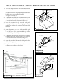
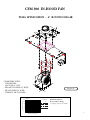
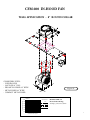
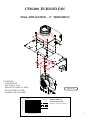
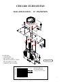
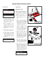
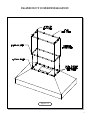
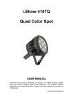
TABLE OF CONTENTS
IMPORTANT SAFETY INSTRUCTIONS
2
SAFETY PROCEDURES
3
PRECAUTIONS FOR RECEIVING AND STORING HOOD
3
WALL HOODS
INSTALLATION - REMOVABLE BACK PANEL
CFM300 - 6" ROUND COLLAR
6
CFM600 - 8" ROUND COLLAR
7
CFM600 - 8" TRANSITION
8
CFM1200 - 10" TRANSITION
9
4,5
ISLAND HOODS
INSTALLATION
10
DUCT COVER INSTALLATION
11
DUCT WORK INSTALLATION
12
CFM600 - 8" TRANSITION
13
CFM1200 - 10" TRANSITION
14
REMOTE FAN - ROOF OR WALL MOUNTED
15
16
VOLUMETRIC FLOW RATE GRAPHS
WIRING DIAGRAM - WALL AND ISLAND HOODS
17
HOOD FEATURES
18
BAFFLE FILTERS - GREASE TROUGHS - HALOGEN LIGHTS
19
CLEANING RECOMMENDATIONS
20
1
PLEASE READ COMPLETE INSTRUCTIONS BEFORE PROCEEDING.
INSTALLATION MUST COMPLY WITH ALL LCOAL CODES.
IMPORTANT:
INSTALLER:
OWNER:
SAFETY
WARNING:
Save these instructions for the Local Electrical Inspector’s use.
Please leave these instructions with this unit for the owner.
Please retain these instructions for future reference.
Turn power circuit OFF at the service panel and lock panel door
before wiring this unit.
IMPORTANT SAFETY INSTRUCTIONS
CAUTION - TO REDUCE THE
RISK OF FIRE, ELECTRIC
SHOCK, OR INJURY TO PEOPLE,
OBSERVE THE FOLLOWING:
1. Use this rangehood only in the
manner intended by the
manufacturer. If you have any
questions,
contact
the
manufacturer - Prizer Hoods.
2. Before servicing or cleaning the
unit, switch power off at service
panel and lock the service
disconnecting means to prevent
power from being switched on
accidentally. When the service
disconnecting means cannot be
locked, attach a tag to the service
panel to indicate power has been
switched off for maintenance.
3. Install this rangehood only with
remote fan models rated
maximum 12.8A or in-hood fans
manufactured by Prizer Hoods,
models CFM300, CFM600,
CFM1200.
CAUTION - TO REDUCE THE
RISK OF A RANGETOP GREASE
FIRE:
1. Never leave cooktop surface
unattended while on high
setting.
2.
3.
4.
Boilovers cause smoke and greasy
spillovers may ignite. Heat oils
slowly on low or medium
settings.
Hood fan should always be ON
when cooking on high heat or
when flambeing foods (i.e.
Crepes Suzette, Cherries Jubilee,
Peppercorn Beef Flambe.)
Clean in-hood fans frequently.
Do not allow grease to
accumulate on fan or baffle
filters.
Always use cookware appropriate
for the size of the surface element.
CAUTION - TO REDUCE THE
RISK OF INJURY TO PEOPLE, IN
THE EVENT OF A RANGETOP
GREASE FIRE, OBSERVE THE
FOLLOWING:
1. SMOTHER FLAMES with a
tight-fitting lid, cookie sheet, or
other metal tray. Immediately
turn the gas burner OFF.
2. PREVENT BURNS. If gas
flames do not extinguish
immediately;
EVACUATE
AND CALL THE FIRE
DEPARTMENT.
3. NEVER PICK UP A FLAMING
PAN as you may sustain burns.
4. NEVER USE WATER, wet
dish-cloths or towels as a violent
steam explosion will occur.
5. Use fire extinguisher ONLY if:
• You know you have a class
ABC extinguisher, and you
already know how to operate it.
• The fire is small and contained
in the area where it started.
CAUTION:
FOR
GENER A L
VENTILATION USE ONLY. DO NOT
USE TO EXHAUST HAZARDOUS OR
EXPLOSIVE MATERIALS OR VAPOR.
• The fire department is being
called.
• You can fight the fire with your
back to an exit.
2
SAFETY PROCEDURES FOR INSTALLING
YOUR NEW PRIZER HOOD (continued)
CAUTION - TO REDUCE THE
RISK OF FIRE, ELECTRIC
SHOCK, OR INJURY TO PEOPLE,
OBSERVE THE FOLLOWING:
CAUTION FOR GENERAL
VENTILATION USE ONLY. DO
NOT
USE
TO
EXHAUST
HAZARDOUS OR EXPLOSIVE
MATERIALS OR VAPORS.
A. Installation work and electrical
wiring must be done by a
qualified installer in accordance
with all applicable codes and
standards, including fire rated
construction.
B. Sufficient air is needed for proper
combustion and gas exhaustion
through the flue (duct cover) of
fuel burning cooktop to prevent
backdrafting.
Follow the
equipment
manufacturer’s
guidelines and safety standards
such as those published by the
National
Fire
Protection
Association (NFPA), and the
American Society for Heating,
Refrigeration
and
Air
Conditioning
Engineers
(ASHRAE), and the local code
authorities.
C. When cutting/drilling into a wall
or ceiling, avoid damage to
electrical wiring and other
hidden utilities.
D. In-hood or in-line fans must be
vented to the outdoors.
E. If a ventilation unit is to be
installed over a tub or shower, it
must be marked as appropriate
for the application and be
connected to a GFCI (Ground
Fault Circuit Interrupter) protected branch circuit.
F. NEVER place a control switch
where it can be reached from a
tub or shower.
G. CAUTION - TO REDUCE THE
RISK OF FIRE WITHIN WALLS
OR ROOFS, USE ONLY METAL
DUCTWORK.
H. Install this hood in accordance
with all requirements specified by
the manufacturer of your
cooktop/range.
I. Install this hood using required
clearance from cooking surface to
combustible material specified in
cooktop installation instructions.
READ AND SAVE
UPON RECEIVING YOUR HOOD...
• The high degree of craftsmanship in the construction
and finish of your hood requires careful handling to
ensure proper installation.
• Wearing cotton gloves are preferred. They will protect
the surface from fine scratches and eliminate
fingerprints.
• Do not remove your hood from its carton until you are
ready to hang it.
• Remove all rings, watches, belt buckles, and jackets
(snaps-zippers) to prevent scratches on the hood.
• Do not store your hood anywhere other than within the
carton. If it is necessary to remove your hood from the
carton, place it on a blanket or padded area that will
protect your hood from scratches or indentations.
• If applicable, do not remove the cotton flannel from your
hood until the installation process is complete. It will be
necessary to remove only a small portion on the
back-side for a wall mounted hood in order to position in
place.
• Do not lift the hood by its utensil rail. Place your fingers
under the lower reveal of the hood. Grasp firmly and
lift.
• Located within the hood cavity (behind the baffle filters)
are component parts and halogen bulbs.
3
WALL HOOD INSTALLATION - REMOVABLE BACK PANEL
1. The hood is shipped with the removable back panel and
the transition.
Shipping Screws
Removable Back Panel
Note: The transition is shipped upside down within the
hood. It must be removed then reinstalled.
(See Figures 1 through 3)
Transition
Hood
Assembly
2. To detach the removable back panel and transition from
the hood, remove four (4) screws from the top and four
(4) screws from the back of the unit. (See Figure 1)
3. Detach the transition from the removable back panel
removing four (4) screws. These shipping screws are
needed for re-attaching the transition to the removable
back panel.
4. Secure the transition to the top of the removable back
panel, using the four (4) screw provided. Use duct tape
to seal the joints of the transition and the top of the
removable back panel. (See Figure 2)
5. To detach the removable back panel/transition from the
hood unit, remove four (4) screws from the top and four
(4) screws from the back of the unit. (See Figure 1)
Figure 1.
10" Transition
6. Secure the back side of the removable back panel to the
wall stud. (See Figure 3)
Shipping Screws
Duct Tape
7. Using the wire harness from the remote fan, connect it
to the molex plug within the hood cavity.
Removable Back Panel
Figure 2.
Power in
Hood wiring harness
Remote
Blower
5-wire in
Molex plug
10" Duct
Remote pigtail
connected to 6-pin plug
In-Hood
J-Box
Soffit
Centerline
of Soffit
Removable Back Panel
* Remote pigtail are supplied with remote fans
Figure 4.
(View from back of hood)
Centerline of
Removable Back Panel
Figure 3.
4
WALL HOOD INSTALLATION - (continued)
1. Attach the hood to the removable back panel by aligning
the welded studs on the removable back panel with the
slotted holes on the back of the hood. (See Figure 5)
Soffit
2. Using the screws provided, secure the hood assembly to
the removable back panel. (See Figure 5)
Connector
3. Add 2”x4” wood framing block to aid in securing the top
and rear of the hood to the wall. (See Figure 6)
4. To mount CFM300, CFM600 and CFM1200 fans
within wall hoods. (See Figures 8, 9, 10, 11) (Page 6-9)
5. Install the fan by aligning the fan holes with the welded
studs on the removable back panel. Tighten the fan to
the panel using the hex nuts provided. (See Figures 8, 9,
10, 11) (Page 6-9)
Mounting
Holes
Figure 5.
6. Connect the “Molex” from the fan to the “Molex” plug
on the hood. (See Figure 4.) (Page 4)
7. Attach three wires: black, white and green (#16 AWG) in
1/2” conduit from the service panel to the hood junction
box. Power supply must be rated for 120v, 60Hz, 15
amps (minimum). (See Page 17)
1/2" Thick
Drywall
Screw
2"x 4"
Framing
8. Remove junction box and selected “knockout”. Then
install the strain relief (conduit) connector in the
removable back panel hole. (See Pages 6, 7, 8, 9)
9. Remove the junction box from the rough-in plate.
Connect black wire to power supply black wire, white
wire to power supply white wire, and green wire to
power supply green wire. (See Pages 6, 7, 8, 9)
Hood
Front
Finished Lag Screws (4 total)
Figure 6.
10. Place all wiring connectors inside junction box and
reinstall removable back panel.
Optional
Duct Cover
OPTIONAL DUCT COVER
1. Install the hood as described in “Hood Rough-In Plate Mount”
Note: Be sure to allow enough room for duct cover width
on the top section of the rough-in plate.
Mounting
Screws
2. Slide Duct Cover into opening.
3. Attach Duct Cover from the inside of the hood through filter
opening using the screws provided. (See figure 7)
Note: Do not completely tighten screws until all components
have been installed. At this point, check the alignment of the
duct to the hood. First tighten the four corners to secure the
duct, then tighten the remaining screws.
Figure 7.
5
CFM 300 IN-HOOD FAN
WALL APPLICATION - 6” ROUND COLLAR
COMPATIBLE WITH:
- LOW PROFILE
- SANTA FE 10” TALL
- PRO METAL LINER 28” WIDE
- METAL LINER 28” WIDE
- COMPACT METAL LINER
Figure 8.
CFM300 Fan
Volumetric Flow Rate, CFM
300
Duct Dimensions
8" dia.
250
7" dia.
200
Maximum CFM: 300
Electrical Motor Rating:
1.79 Amps @ 115V AC, 60 Hz
3 1/4" x 10"
150
6" dia.
100
50
0
0
20
40
60
80
Total Equivalent Duct Length, ft.
100
6
CFM 600 IN-HOOD FAN
WALL APPLICATION - 8” ROUND COLLAR
COMPATIBLE WITH:
- LOW PRO-FILE
- SANTA FE 10” TALL
- PRO METAL LINER 28” WIDE
- METAL LINER 28” WIDE
- COMPACT METAL LINER
Figure 9.
CFM600 Fan
Volumetric Flow Rate, CFM
600
Duct Dimensions
550
8" dia.
500
7" dia.
Maximum CFM: 600
Electrical Motor Rating:
4.0 Amps @ 115V AC, 60 Hz
3 1/4" x 10"
450
6" dia.
400
350
300
0
20
40
60
80
Total Equivalent Duct Length, ft.
100
7
CFM 600 IN-HOOD FAN
WALL APPLICATION - 8” TRANSITION
EXCEPTION:
- LOW PRO-FILE
- SANTA FE 10” TALL
- PRO METAL LINER 28” WIDE
- METAL LINER 28” WIDE
- COMPACT METAL LINER
Figure 10.
CFM600 Fan
Volumetric Flow Rate, CFM
600
Duct Dimensions
550
8" dia.
500
7" dia.
Maximum CFM: 600
Electrical Motor Rating:
4.0 Amps @ 115V AC, 60 Hz
3 1/4" x 10"
450
6" dia.
400
350
300
0
20
40
60
80
Total Equivalent Duct Length, ft.
100
8
CFM 1200 IN-HOOD FAN
WALL APPLICATION - 10” TRANSITION
EXCEPTION:
- LOW PROFILE
- SANTA FE 10” TALL
- PRO METAL LINER 28” WIDE
- METAL LINER 28” WIDE
- COMPACT METAL LINER
Figure 11.
CFM1200 FAN
Volumetric Flow Rate, CFM
1250
Duct Dimensions
1175
10" dia.
1100
9" dia.
Maximum CFM: 1200
Electrical Motor Rating:
8.0 Amps @ 115V AC, 60 Hz
8" dia.
1025
950
875
800
0
20
40
60
80
Total Equivalent Duct Length, ft.
100
9
ISLAND HOOD INSTALLATION
INSTALLATION
!
WARNING
To reduce the risk of fire,
use only metal ductwork.
IMPORTANT NOTE:
All hoods must exhaust to the
outdoors.
1. Decide the placement of the
ductwork between the hood and
the outside of the home. Your
island hood has a top discharge
which will run vertically.
2. When not installing a remote
fan, always install a roof cap or
wall cap. Connect 10” round
metal ductwork to the roof cap
and work back towards the hood
location.
3. Use duct tape to seal the joints
between the ductwork sections.
4. A 10” round transition with
backdraft damper is included
with your island hood. It is
recommended that the enclosed
backdraft damper be used in all
installations.
IMPORTANT NOTE:
Do not use ducting smaller than
10” round.
PREPARATION
IMPORTANT NOTE:
When installing a duct cover, the
duct cover must be installed prior to
the hood installation. See Figure 14
(See Page 11) for duct cover
installation instructions or use
instructions packed with duct cover.
1. Remove baffle filters from hood
shell.
2. Remove center filter bank by
removing the 2 screws from each
side.
DO NO DISCARD
THESE PARTS, as they will be
reinstalled after hood installation
is completd. (See Figure 12)
Figure 12.
3. The hood is shipped with the
transition attached.
The
transition is shipped upside down
in the top of the hood and must
be removed then reinstalled.
4. Detach the transition from the
hood by removing the (4)
shipping screws on the top of the
hood assembly.
DO NOT
DISCARD THESE SCREWS.
These shipping screws will be
needed for the reinstallation of
the transition to hood.
5. Invert the transition (the 10”
round collar points away from
top of hood). Use the shipping
screws removed from step 4.
6. When installing a remote fan,
drill a 7/8” hole through hood
framing for conduit wiring. (See
Figure 13 for overall dimensions
and electrical requirements.) See
installation instructions provided
with your fan for mounting and
installation information.
Figure 13.
IMPORTANT NOTE:
Do not place electrical wiring
within the duct work itself.
10
ISLAND DUCT COVER INSTALLATION
Figure 14.
11
ISLAND HOOD DUCT WORK INSTALLATION
!
WARNING
Framing must be structurally
tied together and attached to
the ceiling joists to provide
enough strength to support the
weight of the hood and the
internal blower, if applicable.
1. Cut a 10” diameter opening in
the ceiling to accommodate the
duct work necessary for proper
ventilation.
2. Transfer the overall dimensions
of the hood top plate onto the
finished
ceiling/unfinished
surface. The top plate width is
13”, but overall width will vary
with the size of the hood. (See
Page 4 - Figure 2)
3. Construct the frame using wood
2x4’s. Due to the weight of the
hood, structural support is
necessary. (See Figure 3)
7. While lifting the hood, align
hood mounting holes with
pre-drilled ceiling holes. Slide
5/8” all-thread rods through the
hood mounting holes and
tighten into wood 2x4 framing.
DO NOT OVER TIGHTEN
SCREWS. (See Figure 3)
11. If installing an in-hood or
in-line
fan,
DO
NOT
RE-INSTALL baffle filters and
center filter-bank until blower
installation is complete. (See
in-hood fan installation on
pages 13 and 14)
8. Connect 10” round duct-work
to the hood transition using
sheet metal screws or duct tape.
all
electrical
9. Complete
connections.
(See
Wiring
Diagram on Page 14)
10. Align hood and tighten all nuts
until hood surface is flush with
ceiling. Install #10 x 2” screws
through
remaining
hood
mounting holes near top edge of
hood surface. This additional
support is necessary. (Screws are
included)
Figure 3.
!
WARNING
When making any electrical
connections, make sure
electrical power is turned off
at the power source (or circuit
breaker) before proceeding.
4. Locate and mark the center of
the hood. Attach two wood
2x4’s across the top of the ceiling
joists. (See Figure 3)
5. Drill four 3/8” holes in the 2x4’s
to match the pattern on the top
of the hood. (See Figure 3)
Remove hood baffle filters and
6. loosen hood filter-bank prior to
installation of hood. See page
10 for direction. (See Figure 12)
!
WARNING
Island hoods are very heavy!
A minimum of three installers
are required to lift the hood to
the ceiling.
Figure 4.
12
CFM 600 IN-HOOD FAN
CHIMNEY AND ISLAND APPLICATION - 8” TRANSITION
EXCEPTION:
- MANHATTAN WALL 36” WIDE
- MANHATTAN WALL 42“ WIDE
- MANHATTAN ISLAND 36” WIDE
- MANHATTAN ISLAND 42” WIDE
THE ABOVE MUST BE USED WITH
AN 8” ROUND COLLAR WITH
BACKDRAFT DAMPER
CFM600 Fan
Volumetric Flow Rate, CFM
600
Duct Dimensions
550
8" dia.
500
7" dia.
Maximum CFM: 600
Electrical Motor Rating:
4.0 Amps @ 115V AC, 60 Hz
3 1/4" x 10"
450
6" dia.
400
350
300
0
20
40
60
80
Total Equivalent Duct Length, ft.
100
13
CFM 1200 IN-HOOD FAN
CHIMNEY AND ISLAND APPLICATION - 10” TRANSITION
EXCEPTION:
- MANHATTAN WALL 36” WIDE
- MANHATTAN WALL 42“ WIDE
- MANHATTAN ISLAND 36” WIDE
- MANHATTAN ISLAND 42” WIDE
THE ABOVE MUST BE USED WITH
AN 8” ROUND COLLAR WITH
BACKDRAFT DAMPER
CFM1200 FAN
Volumetric Flow Rate, CFM
1250
Duct Dimensions
1175
10" dia.
1100
9" dia.
Maximum CFM: 1200
Electrical Motor Rating:
8.0 Amps @ 115V AC, 60 Hz
8" dia.
1025
950
875
800
0
20
40
60
80
Total Equivalent Duct Length, ft.
100
14
REMOTE FAN - ROOF MOUNT OR WALL MOUNT
Remote Fan
Round Ducting
Cabinet/ Soffit
Transition
Remote Fan
Hood Height
10” or 18”
Countertop
To Hood
30” - 36”
Hood Depth
22”, 24”
27”, 30”, 33”
Countertop
To Floor
36”
(standard)
Figure 12.
15
REMOTE FANS
MODEL
VOLUMETRIC FLOW RATE FOR EQUIVILENT DUCT LENGTHS
CFMR600 REMOTE FAN
24"
14 5/8"
5 7/8"
3 1/2"
8"
Volumetric Flow Rate, CFM
CFMR600 REMOTE FAN
600
Duct Dimensions
550
8" dia.
500
7" dia.
6” dia.
400
Maximum CFM: 600
Electrical Motor Rating:
4.3 Amps @ 115V AC, 60 Hz
Duct Size at Discharge:
8" Square-to-round transition
See ventilator & transition pages for use
with hood series.
350
300
28"
3 1/4” x 10”
450
APPLICATION
20 3/4"
0
20
40
60
80
Total Equivalent Duct Length, ft.
100
CFMR1000 REMOTE FAN
CFMR1000 REMOTE FAN
17 5/8"
26 1/4"
5 /8"
7
4"
10"
28"
Volumetric Flow Rate, CFM
1000
900
10" dia.
800
9” dia.
8” dia.
700
7” dia.
600
3 1/4”x10”
500
400
20 3/4"
Duct Dimensions
CFMR1400 REMOTE FAN
6” dia.
0
20
40
60
80
Total Equivalent Duct Length, ft.
100
CFMR1400 REMOTE FAN
14"
4"
10"
28"
20 3/4"
17 5/8"
Volumetric Flow Rate, CFM
1500
26 1/4"
Maximum CFM: 1000
Electrical Motor Rating:
7.8 Amps @ 115V AC, 60 Hz
Duct Size at Discharge:
10" Square-to-round transition
See ventilator & transition pages for use
with hood series.
Duct Dimensions
1400
10" dia.
1300
9" dia.
8" dia.
1200
1100
Maximum CFM: 1400
Electrical Motor Rating:
12 Amps @ 115V AC, 60 Hz
Duct Size at Discharge:
10" Square-to-round transition
See ventilator & transition pages for use
with hood series.
1000
900
0
20
40
60
80
Total Equivalent Duct Length, ft.
100
16
4
5
6
W
G
R
BL
BK
W
4
5
6
TO LOW. SETTING
TO MED. SETTING
TO HIGH SETTING
BLUE
RED
3
3
BK
BLACK
REMOTE
REMOTE
FAN
INTERNAL
BLOWER
CFM600 OR
CFM1000
G
R
BL
BK
W
2
16
15
14
1
R
1
BL
2
4
5
6
6-PIN
CONNECTOR
1
2
3
1
2
3
17
16
YELLOW
11
WHITE
NOT USED
TO TERMINAL
WHITE
3-LIGHT
UNIT
1
SEE DETAIL
17
WHITE
RED
14
6-PIN
5 CONNECTOR
4
6
NOT USED
HALOGEN
LIGHT
15
14
BLACK
BLUE
5
16
15
L1
1
5
11
21
12
1
WHITE
YELLOW
BLACK
2-LIGHT
UNIT
LEFT
WHITE
HEATLAMP
(LEFT)
13
HALOGEN
LIGHT
FAN
SWITCH
3
1
2
BLACK
NC < 200F
NO < 200F
1
WHITE
YELLOW
HEATLAMP
(RIGHT)
2-LIGHT
UNIT
RIGHT HALOGEN
LIGHT
HI-HEAT
THERMOSTAT
3
2
WHITE
YELLOW
WHITE
BLACK
11
1
17
9
2
DIODE
BROWN
7
6
8
BLACK
BLACK
BLACK
BLACK
2
1
2
1
3
2
1
TERMINAL BLOCK
5
9
WHITE
BLACK
GREEN
3-LIGHT UNITS ONLY
18
TYPICAL OF BOTH 2-LIGHT UNITS
LIGHT
SWITCH
HEATLAMP
SWITCH
(LEFT)
HEATLAMP
SWITCH
(RIGHT)
WIRING DIAGRAM FOR WALL AND ISLAND HOODS
N
L1
G
WIRING DIAGRAM FOR WALL
AND ISLAND HOODS
17
HOOD FEATURES
Model
Lighting
Filters
WALL HOODS
Halogen &
Heat
LP 30” - 42”
Halogen 2
THIN BAFFLES
LP 48” - 66”
Halogen 3
THIN BAFFLES
INCL 30” - 42”
Halogen 2
THICK BAFFLES
INCL 48” - 66”
Halogen 3
THICK BAFFLES
INBQ 30“ - 42”
Halogen 2
THICK BAFFLES
INBQ 48” - 66”
Halogen 3
THICK BAFFLES
BONZ 30” - 42”
Halogen 2
THICK BAFFLES
BONZ 48” - 66”
Halogen 3
THICK BAFFLES
CONN 30” - 42”
Halogen 2
THICK BAFFLES
CONN 48” - 66”
Halogen 3
THICK BAFFLES
ASPEN 30” - 42”
Halogen 2
THICK BAFFLES
ASPEN 48” - 66”
Halogen 3
THICK BAFFLES
SNFE-10” TALL 30” - 42”
Halogen 2
THIN BAFFLES
SNFE-10” TALL 48” - 66”
Halogen 3
THIN BAFFLES
SNFE-18” TALL 30” - 42”
Halogen 2
THICK BAFFLES
SNFE-18” TALL 48” - 66”
Halogen 3
THICK BAFFLES
LONDON FLAT 36” - 42”
Halogen 2
MESH FILTERS
LONDON FLAT 48” - 66”
Halogen 3
MESH FILTERS
HAMPTON-I 36” - 42”
Halogen 2
THICK BAFFLES
HAMPTON-I 48” - 66”
Halogen 3
THICK BAFFLES
LARA-I 36” - 42”
Halogen 2
THICK BAFFLES
LARA-I 48” - 66”
Halogen 3
THICK BAFFLES
LARE-I 36” - 42”
Halogen 2
THICK BAFFLES
LARE-I 48” - 66”
Halogen 3
THICK BAFFLES
MANH-I 36” - 42”
Halogen 4
THICK BAFFLES
MANH-I 48” - 66”
Halogen 6
THICK BAFFLES
WRAN-I 36” - 42”
Halogen 2
THICK BAFFLES
WRAN-I 48” - 66”
Halogen 3
THICK BAFFLES
HAMPTON 30” - 42”
Halogen 2
THICK BAFFLES
HAMPTON 48” - 66”
Halogen 3
THICK BAFFLES
LARA 30” - 42”
Halogen 2
THICK BAFFLES
LARA 48” - 66”
Halogen 3
THICK BAFFLES
LARE 30” - 42”
Halogen 2
THICK BAFFLES
LARE 48” - 66”
Halogen 3
THICK BAFFLES
MANH 36” - 42”
Halogen 2
THICK BAFFLES
MANH 48” - 66”
Halogen 3
THICK BAFFLES
WRAN 36” - 42”
Halogen 2
THICK BAFFLES
WRAN 48” - 66”
Halogen 3
THICK BAFFLES
CMLSS (all sizes)
Halogen 2
MESH FILTERS
MLSS 28”
Halogen 2
THICK BAFFLES
MLSS 34” - 46”
Halogen 2
THICK BAFFLES
MLSS 52” - 70”
Halogen 3
THICK BAFFLES
PMLSS 28”
Halogen 2
THICK BAFFLES
PMLSS 34” - 46”
Halogen 2
THIN BAFFLES
PMLSS 52” - 70”
Halogen 3
THIN BAFFLES
MLFS 30” - 42”
Halogen 2
THICK BAFFLES
MLFS 48” - 72”
Halogen 3
THICK BAFFLES
MLSS-I 30” - 42”
Halogen 2
THICK BAFFLES
MLSS-I 48” - 72”
Halogen 3
THICK BAFFLES
Available Widths
Depth
Height
NUMBER OF FILTERS PER WIDTH
30”
2
36”
2
42”
2
48”
3
54”
3
60”
4
66”
4
22”
18”
30”
2
36”
2
42”
3
48”
3
54”
4
60”
4
66”
5
24”
18”
2
30”
2
36”
4
3
42”
6
3
48”
6
4
54”
8
4
60”
8
5
66”
10
30”
2
36”
2
42”
3
48”
3
54”
4
60”
4
66”
5
24”
18”
30”
2
36”
2
42”
3
48”
3
54”
4
60”
4
66”
5
24”
18”
30”
2
36”
2
42”
3
48”
3
54”
4
60”
4
66”
5
24”
18”
30”
2
36”
2
42”
2
48”
3
54”
3
60”
4
66”
4
22”
10”
30”
2
36”
2
42”
3
48”
3
54”
4
60”
4
66”
5
24”
18”
18”
27”
30” 33”
36”
2
42”
3
48”
4
54”
5
60”
6
66”
7
24”
36”
4
42”
6
48”
6
54”
8
60”
8
66”
10
34”
36”
4
42”
6
48”
6
54”
8
60”
8
66”
10
34”
36”
4
42”
6
48”
6
54”
8
60”
8
66”
10
34”
36”
4
42”
6
48”
6
54”
8
60”
8
66”
10
34”
36”
4
42”
6
48”
6
54”
8
60”
8
66”
10
34”
18”
ISLAND
18” NOT
INCLUDING
DUCT COVER
18” NOT
INCLUDING
DUCT COVER
18” NOT
INCLUDING
DUCT COVER
6” NOT
INCLUDING
DUCT COVER
18” NOT
INCLUDING
DUCT COVER
CHIMNEY
30”
2
36”
2
42”
2
48”
3
54”
3
60”
4
66”
4
24”
30”
2
36”
2
42”
2
48”
3
54”
3
60”
4
66”
4
24”
30”
2
36”
2
42”
2
48”
3
54”
3
60”
4
66”
4
24”
36”
2
42”
3
48”
3
54”
4
60”
4
66”
5
24”
36”
2
42”
3
48”
3
54”
4
60”
4
66”
5
24”
18” NOT
INCLUDING
DUCT COVER
18” NOT
INCLUDING
DUCT COVER
18” NOT
INCLUDING
DUCT COVER
18” NOT
INCLUDING
DUCT COVER
20” NOT
INCLUDING
DUCT COVER
LINERS
29”
2
38”
2
47”
3
1513/16”
111/8”
28”
2
34”
2
40”
3
46”
3
52”
4
58”
4
64”
5
70”
5
191/4”
14”
28”
2
34”
2
40”
2
46”
3
52”
3
58”
4
64”
5
70”
5
221/2”
12”
30”
2
36”
2
42”
3
48”
3
54”
4
60”
4
66”
5
72”
5
24”
18”
34”
18”
36”
4
42”
6
48”
6
54”
8
60”
8
66”
10
72”
10
18
BAFFLE FILTERS, GREASE TROUGHS AND LIGHTS
Baffle Filters
Your baffle filters come with “gripper” knobs to aid in filter
placement and removal. Grab the “gripper” knobs with
your thumb and index finger. Simultaneously, slide and
force the first baffle filter in an upward (slightly pitched)
direction towards the ceiling. (Note: spring clips have been
attached within the framework to prevent the baffle filters
from rattling when fan is operating. These spring clips will
make it difficult to insert and remove baffle filters.) As the
baffle filter is forced upward towards the ceiling,
simultaneously swing the lower portion of the filter down
and out of the framework. Remove the remaining baffle
filters in the same fashion. The first baffle filter removed
may be difficult.......... the remaining filters will follow with
ease.
Baffle filters may be washed in your dishwasher. Simply
place on the lower rack of dishwasher using a normal
cleaning cycle.
To re-install your new/clean baffle filters within the hood
cavity, begin the above process but in reverse. First, place
the clean “grease trough(s)” in the cavity framework
followed by the first of the baffle filters keeping in mind the
first of the baffle filters will be easy to re-install............. the
last baffle filter will be difficult due to the tight fit and
limited space.
Grease Troughs
The “grease trough” rests within the lowest portion of the
rectangular open framework. Check for grease build-up
each month. The “grease trough(s)” may be wiped free of
excess grease and placed on top-shelf of your dishwasher for
cleaning.
Halogen Lights
Halogen lights are included with the purchase of your
hood. They are packaged in a cardboard box and taped
within the interior hood cavity behind the baffle filters. To
purchase halogen bulbs through Prizer Hoods, you may
contact our Customer Service Department or visit your
local home improvement store replacing with a PAR 20 Medium Base, 50 watt, 120 volt, Halogen Flood. Be sure
to take your old halogen bulb with you to ensure your new
bulb is similar in length with the same bulb specifications.
Controls
Always “turn-on” the hood fan prior to cooking in order to
establish an airflow in the kitchen. Allow the fan to remain
Hood Assembly
Baffle/Mesh
filter
grease trough
operating after cooking for a few minutes to clear the air.
This measure will ensure the kitchen remains smoke-free
and fresher smelling.
Fan
The hood’s fan is controlled by a three-speed switch.
Speeds: OFF, LOW, MEDIUM, HIGH are printed next to
the fan control knob and correspond to the fan speed.
Hood Lighting
The halogen lights are controlled by a single light switch.
The lighting has a LOW setting (ambient lighting) and a
HIGH setting (brilliant lighting).
Cleaning Your Stainless Steel Hood
Keep your hood free of grease build-up under the hood’s
surface as well as exterior surfaces. Do not use abrasive
cloths, steel wool, scrubbing pads or scouring powders. Do
not use paper towels or any other coarse cloths for cleaning
stainless steel. Have prepared, a supply of pre-washed,
(100% cotton) flannel cleaning cloths or micro-fiber
cleaning cloths. You may purchase 100% cotton flannel by
the yard at your local fabric store. Pre-wash flannel in hot
water using laundry detergent without fabric softeners and
place in dryer without fabric softening sheets.
We recommend using a stainless steel cleaning spray to
maintain the beautiful luster of your stainless steel hood.
Spray the cleaning/polishing solution directly onto a
cleaning cloth as supposed to spraying the surface of the
hood.
“Clean Source” stainless spray may be purchased by
contacting our Customer Service Department.
19
CLEANING RECOMMENDATIONS
BRUSHED STAINLESS STEEL, HAMMERED STAINLESS, EUROPEAN BLACK STEEL and
MILLENNIUM DISK STAINLESS
The Brushed Stainless Steel Hood should be cleaned with pre-washed flannel cloths and our recommended
“Clean Source” cleaner. Always wipe in a manner which follows the grain. DO NOT clean with paper towels
as they will scratch the surface. Cleaning cloths other than cotton flannel may scratch the surface of the hood.
ANTIQUATED COPPER, ANTIQUATED BRASS
The Antiquated Copper and Antiquated Brass Hoods should be cleaned twice yearly. Use pre-washed flannel
cloths and “S.C. Johnson P-A-S-T-E Wax” available at Lowe’s Home Improvement Centers. Gently apply a small
amount in a circular motion using very light pressure. Rubbing too hard may result in the removal of the finish.
DO NOT clean with paper towels as scratches will occur. Cleaning cloths other than cotton flannel may scratch
the surface of the hood.
MIRRORED STAINLESS STEEL, POWDER COATINGS
The Mirrored Stainless Steel or Powder Coated Hood should be cleaned with pre-washed flannel cloths and any
spray glass cleaner. DO NOT clean with paper towels, as they will scratch the surface of the hood. Different
cleaning cloths other than cotton flannel may scratch the surface of the hood.
MIRRORED COPPER, HAMMERED COPPER, BRUSHED COPPER
The Copper Hood should be cleaned with pre-washed flannel cloths and “Brite Boy” metal polish. Always wipe
in a manner, which follows the grain should a grain pattern exist. DO NOT clean with paper towels, as they
will scratch the surface. Different cleaning cloths other than cotton flannel may scratch the surface of the hood.
MIRRORED BRASS, HAMMERED BRASS, BRUSHED BRASS
The Brass Hood should be cleaned with pre-washed flannel cloths and “Brite Boy” metal polish. Always wipe
in the manner, which follows the grain should a grain pattern exist.. DO NOT clean with paper towels, as they
will scratch the surface. Different cleaning cloths other than cotton flannel may scratch the surface of the hood.
INTERIOR OF HOOD
All hoods are fitted with a brushed stainless steel liner. For cleaning, we recommend using pre-washed flannel
cloths and “Clean Source” cleaner. Always wipe in a manner, which follows the grain. DO NOT clean with
paper towels, as they will scratch the surface of the hood.
BAFFLE FILTERS AND GREASE TROUGHS
Baffle Filters and Grease Troughs may be cleaned in your dishwasher. The grease troughs should first be
cleaned of excess grease with a paper towel, then placed beside the baffle filters in your dishwasher for a thorough
cleaning.
“Clean Source” and “Brite Boy” cleaner may be purchased directly from Prizer Hoods.
20
TROUBLE-SHOOTING TIPS
PROBLEM OR CONDITION
POSSIBLE SOLUTION
A fuse may be blown or the circuit breaker tripped.
Replace the fuse or reset the breaker.
Fan and Lights do not operate
made incorrectly. Contact the installer.
The bulb may have burned out.
Fan runs but Lights do not operate
The fuse for the bulb may have blown.
Switch operation may be faulty.
Fan does not function, but Lights operate
Connect fan directly to a supply cord, by-passing
hood control.
If fan operates, check and replace switch and/or
Excessive fan speed and/or noise
assembly. Adjust if necessary.
Check/tighten fan mounts.
Check for obstructions in damper flap or duct work.
number of transitions/elbows and duct diameter.
Prizer Hoods reserves the right to change specifications or design without notice. Some models are certified for use in
Canada. Prizer Hoods is not responsible for products which are transported from the United States for use in Canada.
Check with your local Canadian distributor or dealer.
UL
C UL
®
®
FILE # 204107
4/2012
21