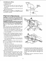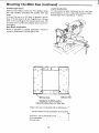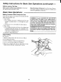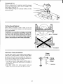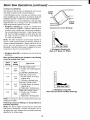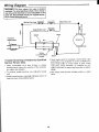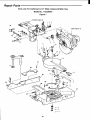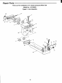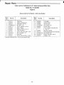
1
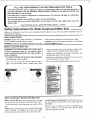
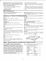
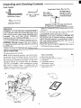
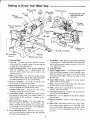
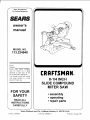
f
Save This Manual
For Future Reference
_'_
S£ARS
owner's
manual
MODEL NO
113.234940
Serial
Number
Model
and
serial
numbers
CRRFTSMRN
may be found
on a plate
attached
to your saw, at the
back of the Miter Saw base.
You should record both model
and serial number
in a safe
place for future
8-1/4 INCH
SLIDE COMPOUND
MITER SAW
use.
FOR YOUR
SAFETY
• assembly
• operating
• repair parts
READ ALL
INSTRUCTIONS
CAREFULLY
J
I/
Sears Roebuck
Pad No. SP6005
and Co,
Hoffman
Estates,
Form No. SP6005-1
IL 60179 US.A.
Printed
in Taiwan
7/97
I
FULL ONE YEAR WARRANTY
ON CRAFTSMAN
BENCHTOP
TOOLS
If this Miter Saw fails due to a defect in material or workmanship, within one year from the date of
purchase, RETURN IT TO THE NEAREST SEARS SERVICE CENTER IN THE UNITED STATES, and
Sears will repair it, free of charge.
If this Miter Saw is used for commercial or rental purposes, this warranty will apply for ninety days
from the date of purchase.
This warranty applies only while this product is in the United States•
This warranty gives you specific legal rights, and you may also have other rights which vary from
state to state.
Sears, Roebuck and Co., D/817 WA Hoffman Estates, IL. 60179
Safety Instructions
For Slide Compound Miter Saw
Safety is a combination of common sense, staying alert and knowing how your miter saw works. Read this manual to
understand this miter saw.
m
Safety Signal Words
DANGER: means if the safety information is not followed
someone will be seriously injured or killed.
WARNING:
means if the safety information
is not fol-
lowed someone could be seriously injured or killed.
CAUTION: means if the safety information is not followed
someone might be injured.
Before Using The Miter Saw
serious, permanent injury, do not plug the miter
saw in until the following steps have been satisfacJ WARNING: To avoid mistakes that could cause
torily completed.
- Completely assemble and align saw. (See "Assembly"
and "Alignment" sections within.)
• Learn the use and function of the ON-OFF switch,
upper and lower blade guards, handle latch, bevel
clamp, cover plate stop screw, and fence clamps. (See
"Getting to Know Your Miter Saw" section within.)
• Review and understand all safety instructions and
operating procedures in this manual.
° Review the maintenance methods for this miter saw.
(See "Maintenance" section within).
• Find and read the following labels on the miter saw:
NN;_" ....
When
Installing
Or Moving
The Miter Saw
Before moving the saw, lock the miter, bevel, carriage
lock and power head positions. Unplug the power cord,
To avoid back injury, get help when you need to lift the
saw.
Never
handle,
shock.
carry
the
Damage
Damage
tool
to
by the
cord
insulation
to wire connections
or power
could
cause
could
head
trigger
an
electric
cause
a tire.
Avoid Dangerous
dry, indoor place
well lighted.
Environment.
protected
from
Use the miter saw in a
rain. Keep work area
Place the saw so neither the user nor
forced to stand in line with the blade.
could injure people in its path.
bystanders
are
Thrown
debris
To avoid injury from unexpected saw movement:
• Place the miter saw on a firm level surface where there
is plenty of room for handling and properly supporting
the workpiece.
• Support the miter saw so the table is level and the saw
does not rock.
• Bolt or clamp the saw to its support.
Never Stand On Tool. Serious injury could occur if the
tool tips or you accidentally hit the cutting tool. Do not
store anything above or near the tool where anyone
might stand on the tool to reach them.
Before
Each
Disconnect The Miter Saw. To avoid injury from accidental starting, unplug the saw, before changing the
setup, changing the blade or adjusting anything.
Compare the direction of rotation arrow on the guard to
the direction arrow on the blade. The blade teeth should
always point downward at the front of the saw
Tighten the arbor screw.
Tighten the cover plate stop screw.
Check For Damaged Parts. Check for:
Proper Alignment of moving parts,
• Make sure your fingers do not touch the plug's metal
prongs when plugging or unplugging the miter saw.
• This TOOL. IS DOUBLE INSULATED to give
added protection. Double insulation does not take
place of normal safety precautions when operating
tool. When servicing this double insulated tool,
only identical parts.
you
the
this
use
Binding of moving parts,
Broken parts,
Stable mounting,
Function of arm return spring and lower guard: Push
the arm all the way down, then let it rise up until it
stops by itself. Check the lower guard to see if it closed
fully. If it did not, follow the instructions in the "Trouble
Shooting" section.
• Smooth, solid movement of sliding assembly
• Other conditions that may affect the way the miter saw
works.
If any part of this miter saw is missing, bent, or broken in
any way, or any electrical parts don't work, turn the saw
off and unplug it. Replace damaged, missing, or failed
parts before using the saw again.
In Place, in working order, and in proper
Maintain Tools With Care. Keep the miter saw clean for
best and safest performance. Follow instructions for lubri-
To Protect Your Eyes, Hands,
caring. DON'T put lubricants on the blade while it's spinning.
Remove Adjusting
before turning it on.
Keys
And
Wrenches
from tool
To avoid injury from jams, slips or thrown pieces:
• Use Only Recommended Accessories. (See "Accessory" section within.) Consult this Owner's manual for
recommended accessories. Follow the instructions that
come with the accessories, The use of improper accessories may cause risk of injury to persons.
• Choose the right 8-1/4 inch diameter blade for the
material and the type of cutting you plan to do.
Damaged electric cords,
Plan Ahead
shock:
Use
Inspect your miter saw.
Keep Guards
adjustment.
To avoid injury or death from electrical
• Make sure the blade is sharp, undamaged and properly aligned. With the saw unplugged, push the powerhead all the way down. Hand spin the blade and check
for clearance. Tilt the power-head to 45 degree bevel
and repeat the check. If the blade hits anything, make
the adjustments shown in the Maintaining Maximum
Cutting Capacity section.
• Make sure the blade and arbor collars are clean.
• Make sure the collars' recessed stdes are facing the
blade.
• Using the 1/4" hex end of combination wrench (supplied) or a 1/2-inch box end wrench, make sure the
arbor screw is firmly hand tightened.
• Make sure all clamps and locks are tight and there ts
no excessive play in any parts.
Keep Work Area Clean. Cluttered areas and benches
invite accidents. Floor must not be slippery
To avoid burns or other fire damage, never use the saw
near flammable liquids, vapors or gases.
Face and Ears
Know Your Miter Saw. Read and understand the
owner's manual and labels affixed to the tool. Learn its
applications and limitations as well as the specific potential hazards peculiar to this tool.
To avoid injury from accidental contact with moving parts,
don't do layout, assembly_ or setup work on the miter saw
while any parts are moving.
Avoid Accidental Starting. Make sure switch is "OFF"
before plugging miter saw into a power outlet.
Plan your work.
Use The Right Tool. Don't force tool or attachment to do
a job it was not designed to do. Use a different tool for
any workpiece that can't be held in a solidly braced, fixed
_ositlon.
CAUTION: Because of the sliding action of this
saw this machine is not designed for cutting metals. Use this miter saw to cut only wood and wood
like products. Other material may shatter, bind on
the blade, start fires or create other dangers.
Safety Instructions
for Miter Saws (continued)
sudden slip could cause fingers or hand to move into
the blade.
Dress for safety.
Any power miter saw can throw foreign objects into the
eyes. This can result in permanent eye damage. Wear
safety goggles (not glasses) that comply with ANSI Z87.1
(shown on package). Everyday eyeglasses have only
impact resistant lenses. They are not safety glasses.
Safety goggles are available at area stores. Glasses or
goggles not in compliance with ANSI Z87.1 could seriously hurt you when they break.
WEAR
• Don't Overreach.
Keep good footing and balance.
• Keep your face and body to one side of sawblade, out
of line with a possible thrown piece.
• Never cut Freehand:
- Brace your workpiece solidly against the fence and
table top so it will not rock or twist during the cut.
- Make sure there's no debris between the workpiece
and its supports.
- Make sure no gaps between the workpiece, fence and
table will let the workpiece shift after it is cut in two.
YOUR
• Cut only one workpiece at a time.
- Do not wear loose clothing, gloves, neckties or jewelry
(rings wrist watches) They can get caught and draw
you into moving parts.
• Wear nonslip footwear.
• "lie back long hair.
• Roll long sleeves above the elbow.
• Noise levels vary widely. To avoid possible hearing
damage, wear ear plugs or muffs when using miter
saw for hours at a time.
• Keep the cut off piece free to move sideways after it's
cut off. Otherwise, it could get wedged against the
blade and thrown violently
• Clear everything except the workpiece and related
support devices off the table before turning the miter
saw on,
• Secure Work, Use clamps or a vise to help hold the
work when it's practical.
Use extra caution with large, very small or awkward
workpieces:
• Use extra supports (tables, saw horses, blocks, etc.)
for any workpieces large enough to tip when not held
down to the table top.
• Never use another person as a substitute for a table
extension, or as additional support for a workpiece that
is longer or wider than the basic miter saw table or to
help feed, support or pull the workpiece.
• For dusty operations, wear a dust mask along with
safety goggles.
Inspect your workpiece.
• Make sure there are no nails or foreign objects in the
part of the workpiece to be cut.
Plan your work to avoid thrown pieces which can
occur when the werkpiece binds on the blade and is torn
from your hands.
Plan how you will make the cut. Always:
• Do not use this saw to cut pieces too small to let you
easily hold the work while you keep the thumb side of
your index (pointer) finger against the outside edge of
the fence.
• Make sure the blade is not spinning.
• Raise the blade.
• Slide the saw out above the front edge of the work
piece before starting saw. and
• Push the sawblade down on top of the wood and back
toward the rear of the saw to make the cut.
I
cut. The blade can suddenly climb up on top of the
I workpiece
DANGER: NEVER
pullitself
the saw
toward
and force
toward
you. you during a I
Plan how you will hold the workpiece from
finish:
start to
• When cutting irregularly shaped workpieces, plan your
work so it will not slip and pinch the blade and be torn
from your hands. A piece of molding, for example,
must lie flat or be held by a fixture or jig that will not let
it twist, rock or slip while being cut.
• Properly support round material such as dowel rods, or
tubing. They have a tendency to roll while being cut,
causing the blade to "bite." To avoid this, always use a
fixture designed to properly hold your workpiece.
• Avoid awkward operations and hand positions where a
Whenever
Saw Is Running
WARNING: Don't allow familiarity (gained from frequent use of your miter saw) to cause a careless
mistake. A careless fraction of a second is enough
to cause a severe injury.
Before starting your cut, watch the miter saw while it
runs. If it makes an unfamiliar noise or vibrates a lot, stop
immediately. Turn the saw off. Unplug the saw. Do not
restart until finding and correcting the problem.
Keep Children Away. Keep all visitors a safe distance
from the miter saw. Make sure bystanders are clear of
the miter saw and workpiece.
Never confine the piece being cut off. Never hold it,
clamp it, touch it, or use length stops against it while the
blade is spinning. It must be free to move sideways on its
own. If confined, it could get wedged against the blade
and be thrown violently.
Let the blade reach full speed before cutting. This will
help avoid thrown workpieces.
!
Don't Force Tool. It will do the job better and safer at its
designed rate. Feed the saw into the workpiece only fast
enough to let the blade cut without bogging down or binding.
Before freeing jammed material:
• Turn miter saw "OFF" by releasing trigger switch.
• Wait for all moving parts to stop.
the power
• Release the switch,
wait for all moving
hands.
head down.
keeping the power head down and
parts to stop before moving your
• If blade doesn't stop within 6 seconds, unplug the saw
and follow the instructions
in the Trouble Shooting section for fixing the blade brake before using the saw
again
• Unplug the miter saw.
After finishing a cut:
Before Leaving
• Keep holding
The Saw
Never Leave Tool Running Unattended,
off. Wait for all moving parts to stop
Turn power
Make Workshop
Child Proof.
Lock the shop. Disconnect master switches.
Store tool away from children and
others not qualified to use the tool,
Glossary of Terms for Woodworking
Miter Cut
Arbor
The shaft on which
Bevel Cut
a cutting
tool is mounted.
An angle cutting operation
made through the face of the
workpiece.
Compound
Cut
A simultaneous
bevel and miter cutting operation.
Crosscut
An angle cutting
workpiece.
Resin
operation
made across
the width
of the
A sticky, sap based substance that has hardened.
Revolutions
Per Minute (RPM)
The number of turns completed
by a spinning
object
one minute
Sawblade
Path
in
A cutting operation
made across the width of the workpiece.
Dado
A non-through
cut which produces
a square sided notch
or trough in the workpiece
Freehand
The area of the workpiece or table top directly in line with
either the travel of the blade or the part of the workpiece
which will be, or has been, cut by the blade
Set
Doing a cut without holding the workpiece
against both
the table and fence. Most workpieces
can be held down
with your hand. Large or wide pieces should be clamped
to the fence or table.
Gum
Workpiece
The item on which the cutting operation
is being performed.
The surfaces
of a workpiece
are commonly
A sticky,
Heel
sap based
to as faces, ends, and edges.
of the blade.
of
material
removed
cut or the slot produced
or partial cut.
Supply
and
Motor
by the
blade
by the blade
in a
in a non-
Specifications
type fuse or circuit
breaker.
To avoid shock
if power
cord is worn or cut, or damaged
immediately.
Requirements
The A-C motor used on this tool is an universal non-reversible type, having the following specifications:
hazprofor
operation
using the voltage
shown.
Connect
tool
to a power line with the appropriate
voltage
and a
1S-amp branch
circuit.
Use a 15-amp time delay
have it replaced
/----Edge
and Electrical
WARNING:
To avoid electrical
hazards,
fire
ards or damage
to the tool, use proper circuit
tection.
Your
tool
is wired
at the factory
way,
tooth is bent (or
from wood products
Motor Specifications
Power
referred
that the tip of the sawblade
from tile face of tile blade
Face
Misalignment
Kerf
The amount
through
through
residue
The distance
set) outward
or fire,
in any
Max Developed
H.F i 2-1/2
Voltage
110-120
Amperes
10
Hertz (Cycles)
6O
Phase
Single
RPM
5000
Rotation
Brake
of Shaft
Clockwise
Automatic
I
Motor Specifications
General
Electrical
and Electrical
Requirements
(continued)
Connections
DANGER: To avoid electrocution:
1. Use only identical replacement parts when servicing. Servicing should be performed by a
qualified service technician.
2. Do not use in rain or where floor is wet.
This tool is intended
only.
110-120
Volt,
for
60 Hz. Tool
indoor
residential
I
minals of plug when installing or removing the
I WARNING Do not permit fingers to touch the ter- [
plug to or from the outlet.
If power cord is worn or cut, or damaged in any way,
have it replaced immediately.
use
Information
Double Insulated
The miter saw is double insulated to provide a double
thickness of insulation between you and the tool's electrical system. All exposed metal parts are isolated from the
internal metal motor components with protecting insulation.
Polarized
Plug
Your unit has a plug that looks like the one shown.
To reduce the risk of electrical shock, this appliance has
a polarized plug (one blade is wider than the other). This
plug will fit in a polarized outlet only one way, if the plug
does not fit fully in the outlet, reverse plug. If it still does
not fit, contact a qualified electdcian to install the proper
outlet. Do not change the plug in any way.
Motor Safety
WARNING: Double insulation
does not take the I
place of normal safety precautions when operating
this tool.
I
Protection
IMPORTANT: To avoid motor damage, this motor should
be blown out or vacuumed frequently to keep sawdust
from interfering with normal motor ventilation.
a Motor Is Overloaded-Overloading
can occur if you
feed too rapidly or make too many start/stops in a
short time.
1. Connect this tool to a 110-120V 15 amp branch circuit
with a 15 amp time delay fuse or circuit breaker. Using
the wrong size fuse can damage the motor.
b Line voltages are more than 10% above or below the
nameplate voltage. For heavy loads, however, the
voltage at motor terminals must equal the voltage
specified on nameplate.
2. If the motor won't start, release the trigger switch
immediately. Unplug The Tool. Check the saw blade
to make sure it turns freely. If the blade is free, try to
start the motor again. If the motor still does not start,
refer to the "Motor Trouble-Shooting Chart".
3. If the motor suddenly stalls while cutting wood, release
the trigger switch, unplug the tool, and free the blade
from the wood. The motor may now be restarted and
the cut finished.
c Improper or dull saw blade are used.
5. Most motor troubles may be traced to loose or incorrect connections, overload, low voltage (such as small
size wire in the supply circuit) or to overly long supply
circuit wire. Always check the connections, the load
and the supply circuit whenever motor doesn't work
well. Check wire sizes and length with the Wire Size
Chart below.
4. Fuses may "bloW' or circuit breakers may l_ip frequently i_
Wire Sizes
NOTE: Make sure the proper extension cord is used and
is in good condition.
The use of any extension cord will cause some loss of
power. To keep this to a minimum and to prevent overheating and motor burn-out, use the table below to determine the minimum wire size (A.W.G.) extension cord.
Extension Cord
Length
Wire Sizes Required
(A.W.G.)
110-120V
0-25 Ft
18
26-50 Ft.
16
Table of Contents
Section
Page
Warranty ........................................................................
2
Safety Instructions For Slide Compound Miter Saw ...... 2
When Installing Or Moving The Miter Saw ................. 2
Glossary of Terms for Woodworking ............................. 5
Motor Specifications and Electrical Requirements ........ 5
Power Supply and Motor Specifications ..................... 5
General Electrical Connections .................................. 6
Table of Contents ..........................................................
7
Unpacking and Checking Contents .............................. 8
Tools Needed .............................................................
8
Unpacking ..................................................................
8
Getting to Know Your Miter Saw ................................... 9
Assembly ....................................................................
10
Removing or Installing the Blade .............................. 10
Assembling Dust Elbow ............................................ 11
Alignment (Adjustments) ............................................. 11
Mounting The Miter Saw ............................................. 14
Safety Instructions for Basic Saw Operations ............. 16
Basic Saw Operations ................................................. 18
Making Common Slide Compound Cuts .................. 18
Slide Cutting .............................................................
19
Body and Hand Position ........................................... 19
Miter Cut ...................................................................
20
Bevel Cut ..................................................................
20
Section
Page
Compound Cut .........................................................
21
Cutting Bowed Material ............................................ 21
Hold Down Clamp Installation .................................. 21
Hold Down Clamp Usage ......................................... 22
Workpiece Support ...................................................
22
Rough Cutting A Dado ............................................. 23
Helpful Hints When Cutting Compound Miters ......... 23
Maintenance and Lubrication ...................................... 25
Maintenance .............................................................
25
Replacing Carbon Brushes ...................................... 25
Lower Blade Guard ..................................................
25
Lubrication .......................................................
25
Sears Recommends the Following Accessories ......... 26
Recommended Accessories ..................................... 26
Prohibited Accessories ............................................. 26
Troubleshooting Guide ................................................
27
Motor .......................................................................
27
General ....................................................................
27
Wiring Diagram ...........................................................
28
Trouble Shooting Of Brake By Qualified Service Person
Only .......................................................................
28
Notes ..........................................................................
29
Repair Parts ................................................................
30
Unpacking and Checking Contents
Tools Needed
Combination
Combination
Square
Draw Light
Line on Board
Along this Edge
1t4" Hex "L" Wrench
(Supplied)
Square Must be True
¢,_,
Straight Edge of
Board 3/4" Thick
This Edge Must be
Perfectly Straight
Adjustable Wrench
Should be no Gap or Overlap when Square
is Flipped Over in Dotted Position
tighten the carriage lock knob to guard against sudden
movement.
Unpacking
WARNING: To avoid injury from unexpected starting or electrical shock, do not plug the power cord
into a power source outlet during unpacking and
assembly. This cord must remain unplugged
whenever you are working on the saw.
Your model of Miter Saw is shipped complete in one box.
To avoid back injury, get help whenever you have
WARNING:
Although compact, this saw is heavy.
to lift the saw.
1. Before removing
List of Loose
the saw from the shipping
2. Remove the miter saw from the carton by lifting with
the handholds located at the base of the saw.
WARNING: if any part is missing or damaged, do
not plug the saw in until the missing or damaged
part is correctly replaced. To avoid electric shock,
use only identical replacement parts when servicing double insulated tools.
3_ Place the saw on a secure, stationary work surface
and look the saw over carefully.
carton
Parts
The following parts are included:
NOTE: Before beginning assembly, check that all paris
are included. If you are missing any part do not assemble the saw, Contact your Sears Service Center to get
the missing part. Sometimes small parts can get lost in
packaging material. Do not throw away any packaging
until saw is put together. Check packaging for missing
parts before contacting Sears, A complete parts list
(Repair Par[s) is at the end of the manual. Use the list to
identify the number of the missing part.
C
A
Carriage
Lock Knob
Hand Hold
Part or Assembly
A.
B.
C.
D,
Qty.
Basic Saw Assembly ................................................
Clamp Assembly (shown on saw) .............................
Dust Elbow ...............................................................
Combination Wrench .................................................
(Assembled on saw)
E, Form Owner's Manual ...............................................
F. Registration Form ......................................................
1
1
1
1
1
1
Getting to Know Your Miter Saw
10
12
Cover Plate
Screw
Lock-off
11 Cover
9 Saw Switch
1 Warning
Labels
3 Depth Adjustment Bolt
with Stop Knob and
Jam Nuts
Handle
Button
14 Upper
13
Blade
Trigger
Switch
7 carriage
/
6 Bevel Adjustment
Stops
Lock Knob
8 Lower Blade
_rd
Table
18
Rear
Foot
Miter Lock Handle
17
Combination
| 5 Base
Wrench
19 Hold Down Clamp
1. Warning
2. Lock
labels.
Pin - The
miter saw can be locked
ered position for compact storage.
carrying and storage applications.
in the low-
Use this only for
3. Depth Adjustment
Bolt - When properly adjusted it
limits the sawblade
travel to approximately
1/4"
below the table. Dados may also be rough cut by
adjusting this bolt.
4. Miter Lock Handle - The miter lock handle securely
locks the miter saw at a desired miter angle. Index points
have been provided at 0, 15, 22.5, 30 and 45 R/L.
5. Bevel
Lock
Handle
- The
the miter saw at a desired
6. Bevel Adjustment
stop the sawblade
bevel
lock handle
locks
bevel angle.
Stops - Bolts that are adiusted
at 0 ° bevel and 45 ° bevel.
7. Carriage
Lock
Knob - Prevents
the
motion by locking the carriage in place.
saws
to
sliding
8. Lower Blade Guard - The blade guard helps protect
your hands from the blade in the raised position. To
avoid binding
on the workpiece,
it retracts as the
blade is lowered.
9. Miter Saw Switch
Handle - The saw handle contains the trigger switch with a lock-off button. The
blade is lowered into the workpiece
by pushing down
on the handle. The saw will return to its upright position when the handle is released.
10. Cover
5 Bevel Lock
Handle
Plate
Stop
Screw
- When
ened. the cover plate is rotated
for blade removal/replacement.
this screw
is loos-
to the rear. allowing
11. Cover Plate - Holds the lower guard and is attached
to upper guard. Prevents the arbor screw from backing out when properly attached with the 10-32 x 1/2"
cover plate stop screw.
12. Lock Off Button
13. OnlOff Trigger Switch - To prevent the trigger from
being accidentally engaged, a lock-off button is provided. To start the tool, press in the lock-off button
and squeeze the trigger. Release the trigger to stop
the miter saw.
14. Upper Blade Guard - Supports the motor handle,
switch, blade and lower guard.
15. Base - Supports table, holds accessories and allows
for work bench or leg set mounting.
16. Table - Sits in base, supports pivot and allows for at
least 45 ° miter left and right.
17. Combination Wrench - Used for 1/4" hex and Phillips head screw adjustments.
18. Rear Foot - Can be adjusted to help better stabilize
the saw base.
19. Hold Down Clamp - Helps to hold workpiece to the
saw.
20. Arbor Lock - (Not shown) Allows user to keep blade
from rotating while tightening or loosening arbor
screw during blade replacement or removal. Make
sure arbor lock is disengaged before the saw is
turned on.
Assembly
WARNING: For your own safety, never connect
plug to power source outlet until all assembly
steps are complete, and you have read and understood the safety and operational instructions.
Removing
or Installing
Cover
Blade G.ua_late
the Blade
Guard
Bearing
WARNING: To avoid injury from a thrown workpiece or thrown pieces of blade, do not use a blade
larger or smaller than 8-1/4" diameter.
WARNING: To avoid injury from unexpected starting, unplug the saw whenever you are removing or
installing the blade.
3over Plate
Stop Screw
/
1. Unplug the saw from the outlet. Cutting head is up.
2. Rotate lower guard out of the way. Loosen the cover
plate stop screw with the phillips end of the combination wrench. (Supplied)
_
Lower
Blade Guard
3. Lift the lower guard up and tilt the lower guard
assembly back so the arbor screw is exposed.
4. Find the arbor lock between the guard and the miter
saw handle. Place the 1/4" Allen end of the combination wrench into the arbor screw.
rLock
5. Press the arbor lock and hold it in firmly while turning
the wrench clockwise. The arbor lock will engage
alter some turning of the wrench.
Arbor Screw
(
NOTE: The arbor lock can be damaged by improper use.
If the arbor lock will not hold, lower the blade down on to
a scrap piece of wood positioned against the fence. This
will serve as an alternate locking means.
6. Unscrew and remove the arbor screw, arbor washer,
outer blade collar, and the blade.
/
Combination
_" Wrench
,iSupplied
NOTE: Pay attention to pieces removed, noting their
position and direction they face (see illustration). Wipe
the blade collars clean of any sawdust before installing
the new blades.
8-1/4"
Blade
Arbor Washer
CAUTION: To avoid cuts from extremely sharp I
teeth: Wear gloves when installing or removing
sawblade.
I
__Inner
Blade
(Do Not
Remove)
7. Install the new 8-1/4" blade (see recommended
accessory list). Make sure the rotation arrow on the
blade matches the clockwise rotation arrow on the
Arbor Screw
Left Hand Thread
upper guard.
8. Install the outer blade collar, blade washer and arbor
screw. Press the arbor lock and turn the arbor screw
counterclockwise to secure the blade. Tighten arbor
screw using moderate force.
t-Outer
Blade Collar
10. Be sure the arbor lock is released so the blade turns
freely.
WARNING: Make sure the collars are clean and
properly arranged. After installing
a new blade,
make sure the blade clears the table slot at the 0 °
and 45 ° bevel positions. Lower the blade into the
table slot and check for any contact with the base
or turn table structure. If blade contacts table, seek
authorized Sears Service.
9. Lower the lower blade guard until the slot in mounting plate rests all the way down on the mounting
screw. Tighten the screw with the Phillips end of
combination wrench.
DANGER: Never use saw without mounting plate
securely in place. It keeps the arbor screw from
falling out if it accidentally loosens, and prevents
the spinning blade from coming off the machine.
If blade contacts turn table, refer to "Alignment" section
for adjustment.
If blade bottoms out on turn table structure, refer to
"Alignment", Depth Stop section for adjustment.
10
Assembling
Dust Elbow
Dust Elbow
1. Locate the dust elbow
2. Unplug power cord.
3. With the miter arm locked in the down position, start
the dust elbow onto the dust nozzle at an angle to
retaining lip.
4. Firmly press the dust elbow the rest of the way onto
the second retaining lip.
NOTE: At first time installation, or if assembled in a cool
or cold climate, the rubber is not as flexible and will be
more difficult to assemble.
D°UzStzle
Alignment (Adjustments)
WARNING: To avoid injury from unexpected starting or electrical shock, do not plug the saw in. The
power cord must remain unplugged whenever you
are working on the saw.
WARNING: Cut material can be thrown. Eyes can be
permanently damaged, Wear your safety goggles.
Step One:
ment)
Blade
Square
to Table
(Bevel
Align-
NOTE: The miter saw was assembled, aligned, and
inspected before shipment. Alignment should be checked
and any adjustments made to insure accurate cuts.
1. Check miter lock knob setting. The miter lock knob
should be at the 0° position. To reset the miter angle,
turn the miter lock knob counterclockwise and move to
0° miter and retighten.
2. Lower the blade and engage the lock pin. Use a combination square to check blade squareness to table. If
the blade does not contact the full length of the square,
(see illustration) follow the alignment procedure.
a Loosen bevel lock knob.
b Grasping upper metal guard, move the cutting head
left or right until blade makes contact with the full
length of the square.
NOTE: If you cannot get to 0 ° bevel, the stop screw may
be in your way. Adjust it down (Ref.: Step d below) so
you may achieve 0 ° bevel.
c Tighten the bevel lock knob
d Loosen the 0 ° bevel stop screw jam nut using adjustable wrench. Adjust 0 ° bevel stop screw up so that
the hex screw head hits the 0 ° stop at the same time
the blade makes contact with the full length of
square. After adjustment is final. Retighten the 0 °
bevel stop screw jam nut.
3. Adjust bevel scale indicator
With the blade square to the table and the 0 ° bevel
stop screw adjusted, if necessary loosen the bevel
indicator screw, using the Phillips end of the combination wrench. Slide the indicator under the Phillips head
screw to line up exactly with the 0 ° bevel mark on the
bevel scale. Retighten the indicator screw.
4. Loosen bevel lock knob and tilt the power head to 45 °
bevel and check the 45 ° bevel stop. The bevel indicator should be on the 45 ° mark, the 45 ° bevel stop
should be in full contact with the 45 ° bevel stop screw,
and the blade should contact the full length of the
square.
5, If adjustment is necessary, repeat steps 2a - 2d for the
45 c bevel stop screw.
11
Alignment
(Adjustments)
(continued)
Step Two:
ment)
Square
Align-
Blade
to Fence
(Miter
WARNING: To avoid injury from unexpected starting or electrical shock, do not plug the saw in. The
power cord must remain unplugged whenever you
are working on the saw.
1. To check blade squareness to fence, lock power head
guard in lower position with the lock pin. Use a combination square. Place the square against the fence and
next to the blade as illustrated. Locate the square
properly so it does not contact the set in the teeth of
sawblacle, giving an inaccurate reading. The sawblade
body should contact the full length of the square.
2. If blade contacts full length of square, no alignment is
necessary, skip a-c below. If blade is not square to the
fence, follow the alignment procedure.
a Loosen the four (4) fence lock bolts.
b Place a combination square against the sawblade
and adjust the fence until it is 90 ° to the blade.
WARNING: Do not start the miter saw without
checking for interference between the blade and
the turn table structure. Damage could result to the
blade if it strikes the turn table structure during
operation of the saw. Broken saw parts could hit
you or others.
c Tighten the four (4) fence lock bolts.
Adjust Miter Scale Indicator
1. Loosen the Phillips screw that holds the indicator in
place.
2. Reposition the indicator to align it with 0° mark, and
retighten screw.
Step Three:
Bevel
Pivot
Adjustment
The slide compound miter saw should bevel by loosening
the bevel lock handle and tilting the power head to the
left. If movement is tight or if there is loosening in the
pivot follow the adjustment procedure,
1. Loosen the bevel lock handle.
Depth Stop
Jam Nuts
2. Turn the hex lock nut with a wrench.
3. Recheck bevel movement of the miter saw. Readjust if
necessary
Step Four:
Cutting
Head Pivot
Adjustment
The slide compound miter saw should rise completely to
the up position by itself. To check this, hold the powerhead down, make sure the lock pin is not engaged and
see if the saw will rise by itself. If the saw will not rise by
itself or if there is play in the pivot joints the following
adjustment is necessary.
1. If the saw does not rise by itself loosen the lock nut on
the pivot bolt.
Pivot Bolt
and Nut
2. If there is play in the joints slightly tighten the lock nut
on the pivot bolt.
3. Recheck the saw travel. Saw should rise freely to its
up travel stop. Check to see that the saw will rise from
all positions and there is no looseness in the pivot. If
saw still won't fully rise, have Sears Service check and
repair it.
Bevel Lock
Handle
Bevel Hex
Lock Nut
WARNING: To keep the nut from working its way
off as you use the saw, at least one thread of the
pivot bolt must always stick out past the nut.
Always keep the nut at least that tight.
12
Step
Five:
The depth
Depth
Stop
stop limits the downward
travel
of the blade
It
allows the blade to go below the work table enough to
maintain
full cutting
capacities,
thereby
cutting
completely through
the workpiece
at the fence
Properly
adjusted the depth stop positions the blade 1/4" below
the table.
WARNING:
to avoid
injury
from
unexpected
start-
ing or electrical
shock, do not plug the saw in. The
power cord must remain unplugged
whenever
you
are work
ng on the saw.
This tool Asfactory set to provide maximum cutting capacity for the 8-1/4" saw blade provided.
When the diameter
of the blade has been reduced due to sharpening,
it may
be necessary
to adjust depth stop to provide maximum
cutting capacity. When a new blade is installed_ it is necessary to check
table structure.
the clearance
of the blade
Adjustment
Screw
to the turn
1. To adjust the depth stop loosen the two (2) jam nuts on
the end of the depth stop bolt.
2. Loosen
the stop knob at the top of the arm
3. The sawblade
is lowered by turning the depth stop bolt
counterclockwise
and raised by turning the bolt clockwise
4. Lower
the blade
into the slot of the turn table.
Check
i
blade clearance
and maximum
cutting distance
(distance from fence where blade enters) to front of work
table slot. Readjust if necessary.
WARNING:
Do
not
start
the
miter
saw
without
checking
for interference
between
the blade and
the turn table structure.
Damage could result to the
blade if it strikes
the
operation
of the saw.
turn
table
structure
during
WARNING:
Failure to tighten the jam nut could let
the depth stop slip and let the blade strike the saw
table. Broken saw parts could hit you or others.
5 Tighten
the large stop knob at the top of arm.
6 Tighten the two (2) nuts on the end of the depth
bolt against the depth stop.
Step
Six:
Rear
Foot
stop
Adjustment
The rear foot can be adjusted to better stabilize the base.
When the saw is placed on a work place surface, the foot
can be adjusted using the following adjustment.
1. Place the saw on a secure,
stationary
work surface.
2. Using the Phillips end of combination
the adjustment
screw
3. Pull foot out until
face
it makes
contact
wrench,
with the work su[-
NOTE: Foot is mounted at a downward
so it will self adjust as it is pulled out
4. Tighten
adjustment
loosen
slanting
angle
screw.
13
Mounting
The Miter Saw
WARNING: To avoid injury from unexpected saw
movement:
a. Before moving the saw, lock the miter lock
knob and lock the power head in the lower
position using the lock pin. Unplug electric
cord.
b. To avoid back injury, get help when you need
to lift the saw more than 10 inches. Hold the
tool close to your body when lifting. Bend your
knees so you can lift with your legs, not you r
back. Lift by using the hand-hold areas at each
side of the bottom of the base.
D
H
J
E
c. Never carry the miter saw by the power cord or
the trigger handle. Carrying the tool by the
power cord could cause damage to the insulation or the wire connections resulting in electric shock or fire.
d. Place the saw so other people cannot stand
behind it. Thrown debris could injure people in
its path.
e. Place the saw on a firm, level surface where
there is plenty of room for handling and properly supporting the workpiece.
G
f. Support the saw so the table is level and the
saw does not rock.
g. Bolt or clamp the saw to its support.
Place the saw in the desired location. The base
saw has nine holes to mount the miter saw labeled
C\
of the
A thru
J. Four smaller holes for "drywall" screws are labeled F,
G, H and J. Five holes for 5/16" bolts are labeled A, B, C,
D and E (see illustration).
If the saw is to be used in one
location, fasten it to the work bench.
NOTE: When mounted on a large flat surface, the miter saw
table is 3-1/2" high. A finished 4 x 4 or a supported 2 x 4 on
edge can be used as work support extension.
14
Mounting
I
The Miter Saw (continued)
Portable Applications
Leg Set Applications
Plywood mount helps protect saw from damage during
the rough handling associated with portable miter saw
usage.
To mount the saw to a 3/4" piece of plywood, use the
three, 5/16 bolt holes A, B and C or` the four 5/16 bolt
holes A, B, D and E or the four drywall screw holes. The
mounting board can then be clamped down to prevent it
from tipping.
Work Bench Applications
To mount saws to below mentioned leg set, use three
holes marked A, B, and C. Attach with hardware shown,
through legset holes indicated by "°" (below).
Mount as specified in portable applications.
workpiece clearances to left and right of saw.
Check for
l
,,_8___
$_o
C Oo
o
oO
O
o
o
o
O
O
©
O
0
o
0
©
oO
o [---) o
'
_k_k Stiffener_Side
Catalog
Legset
No. 9-22246
Mounting
Stiffenei_E_nd
Leg Set
Holes for Miter Saw
Attach miter saw to holes/slots that are blackened in "°"
Recommended
mounting hardware (not included)
Qty
5/16-18 x 1-1/2 hex head bolts (front) .......................... 3
5/16 Iockwashers .........................................................
3
5/16 he× nuts ................................................................
3
15
Safety Instructions
Before
for Basic Saw Operations
Each Use
Inspect
your saw.
caring
ning,
Disconnect
The Miter Saw. To avoid injury from accidental
starting,
unplug the saw, before changing
the
setup, changing the blade or adjusting anything.
Compare
the direction
of rotation arrow on the guard to
the direction
arrow on blade. The blade teeth should
always
point downward
Tighten
the arbor
screw.
the cover
plate stop screw.
Tighten
Check
Damaged
• Proper
Parts.
alignment
• Damaged
of moving
electric
cords,
• Binding
of moving
pads,
• Broken
parts,
• Stable
pads,
of arm return spring and lower guard: Push
all the way down, then let it rise up until it
itself. Check the lower guard to see if it closed
did not. follow the instructions
in the "Trouble
section.
• Smooth,
solid movement
in working
Maintain
Tools With Care.
best and safest performance.
Plan Ahead To Protect
from
To avoid
jams,
slips
or thrown
pieces:
injury
from
accessories
may cause
risk of injury
tool
to per-
missing,
order,
recessed
sides
are facing
the
(supplied)
the arbor
• Make sure all clamps and locks are tight and there
no excessive play in any parts.
or failed
Keep work area clean. Clullered
areas
invite accidents. Floor musl not be slippery
and in proper
is
and benches
To avoid burns or other fire damage, never use the miter
saw near flammable
liquids, vapors or gases.
Keep the miter saw clean for
Follow instructions
for lubri-
Your Eyes, Hands,
the right 8-1/4 inch diameter
blade for the
and the type of cutting you plan to do.
• Using 1/4" hex end of combination
wrench
or !/2-inch
box end wrench,
make sure
screw is firmly hand lightened.
Face and Ears
Know
your
miter
saw.
Read and understand
the
owner's manual and labels affixed to the tool, Learn its
application
and limitations
as well as the specific poten
lial hazards peculiar to this tool.
Dress
for safety.
Any power miter saw can throw foreign objects into the
eyes. This can result in permanent
eye damage.
Wear
safety goggles (not glasses) that comply with ANSI Z87.1
(shown on package),
Everyday
eyeglasses
have only
impact resistant
lenses
They are not safety glasses
Safety
goggles
are available
at Sears
retail stores
Glasses or goggles not in compliance
with ANSI Z87.1
could seriously hurt you when they break.
To avoid injury from accidental contact with moving parts,
don't do layout, assembly, or setup work on the miter saw
while any parts are moving.
Avoid Accidental
Starting.
Make sure switch is "OFF"
before plugging miter saw into a power outlet.
Plan your
Wrenches
• Make sure the collars'
blade,
assmbly.
that may affect the way the miter saw
In Place,
And
• Make sure the blade is sharp, undamaged
and properly aligned. With the saw unplugged,
push lhe powerhead all the way down. Hand spin the blade and check
for clearance.
Tilt the power-head
to 45 degree bevel
and repeal the check. If the blade hits anything,
make
the adjustments
shown in the Maintaining
Maximum
Cutting Capacity section.
• Make sure the blade and arbor collars are clean
If any part of this miter saw if missing, bent, or broken in
any way, or any electrical
parts don't work, turn the saw
Keep Guards
adjustment.
Keys
• Choose
material
mounting
off and unplug it Replace
damaged,
parts before using the saw again.
while its spin-
sons.
• Function
the arm
stops by
fully. If it
Shooting"
• Other conditions
works.
on the blade
Remove
Adjusting
before turning it on
improper
for:
of sliding
put lubricants
• Use Only
Recommended
Accessories.
(See
"Accessory"
section within.) Consult this Owner's manual for recommended
accessories.
Follow the instructions that come with the accessories,
The use of
at the front of the saw.
Check
DON'T
work.
WEAFI
YOUR
Use The Right Tool. Don't force tool or attachment to do
a job it was not designed
to do. Use a different
tool for
any workpiece that can't be held in a solidly braced, fixed
)osition.
CAUTION:
Because
of the sliding
action of this
saw, this machine
is not designed for cutting metals. Use this miter saw to cut only wood, and wood
like products.
Other materials may shatter, bind on
the blade, start fires or create other dangers.
• Do not wear loose clothing, gloves, neckties
(rings, wrist watches) They can get caught
you into moving pads.
* Wear nonslip
footwear.
- Tie back long hair.
16
or jewelry
and draw
I
• Rolllongsleevesabovetheelbow.
and its supports.
• Noise levels vary widely. To avoid possible hearing
damage, wear ear plugs or muffs when using miter
saw for hours at a time.
- Make sure no gaps between the workpiece, fence
and table will let the workpiece shift after it is cut in
• For dusty operations,
safety goggles.
two.
wear a dust mask along with
• Cut only one workpiece at a time.
• Keep the cut off piece free to move sideways after it's
cut off. Otherwise, it could get wedged against the
blade and thrown violently
Inspect your workpiece.
• Make sure there are no nails or foreign objects in the
part of the workpiece to be cut.
• Clear everything except the workpiece and related
support devises off the table before turning the miter
Plan your work to avoid thrown pieces, when the
w0rkpiece binds on the blade and is torn from your
hands.
saw
• Secure Work. Use clamps or a vise to help hold the
work when it's practical.
Plan how you will make the cut. Always:
Use extra caution with large, very small or awkward
workpieces:
• Make sure the blade is not spinning.
• Raise the blade.
° Use extra supports (tables, saw horses, blocks, etc.)
for any workpieces large enough to tip when not held
down to the table top.
• Never use another person as a substitute for a table
extension, or as additional support for a workpiece that
is longer or wider than the basic miter saw table or to
help feed, support or pull the work'piece.
• Slide the saw out above the lronl edge of the workpiece before starting saw, and
• Push the sawblade down on top of the wood and back
toward the rear of the saw to make the cut.
cut. The blade can suddenly climb up on top of the
I DANGER: NEVER pull the saw toward you during a
workpiece and force itself toward you.
Plan how you will hold the workpiece
finish:
• Do not use this saw to cut pieces too small to let you
easily hold the work while you keep the thumb side of
your index (pointer) finger against the outside edge of
the
fence.
from start to
• Avoid awkward operations and hand positions where a
sudden slip could cause fingers or hand to move into
the blade.
• When cutting irregularly shaped workpieces, plan your
work so it will not slip and pinch the blade and be tom
from your hands. A piece of molding, for example,
must lie flat or be he!d by a fixture or jig that will not let
it twist, rock or slip while being cut.
• Don't Overreach. Keep good footing and balance.
• Keep your face and body to one side of sawblade, out
of line wilh a possible throwback.
• Never cut Freehand:
• Properly support round material such as dowel rods, or
tubing. They have a tendency to roll while being cut,
causing the blade to "bite." To avoid this, always use a
fixture designed to properly hold your workpiece.
- Brace your workpiece solidly against the fence and
table top so it will not rock or twist during the cut.
- Make sure there's no debris between the workpiece
Whenever
on.
Saw Is Running
WARNING: Don't allow familiarity (gained from frequent use of your miter saw) cause a careless mistake. A careless fraction of a second is enough to
cause a severe injury.
Don't Force Tool. It will do the job better and safer at its
designed rate. Feed the saw into the workpiece only fast
enough to let the blade cut without bogging down or binding.
Before freeing jammed material:
• Turn miter saw "OFF" by releasing trigger switch.
• Wait for all moving parts to stop.
Before starting your cut, watch the miter saw while it
runs. If it makes an unfamiliar noise or vibrates a lot, stop
immediately. Turn the saw off. Unplug the saw. Do not
restart until finding and correcting the problem.
Keep Children Away, Keep all visitors a safe distance
from the miter saw. Make sure bystanders are clear of
the miter saw and workpiece.
• Unplug the miter saw.
After finishing a cut:
• Keep holding the power head down.
• Release the switch, keeping the powerhead down and
wait for all moving parts to stop before moving your
hands.
Never confine the piece being cut off. Never hold it,
clamp it, touch it, or use length stops against it while the
blade is spinning. It must be free to move sideways on its
own. If confined, it could get wedged against the blade
and be thrown violently.
• If blade doesn't stop within 6 seconds, unplug the saw
and follow the instructions in the Trouble Shooting section for fixing the blade brake before using the saw
again.
Let the blade reach full speed before cutting. This will
help avoid thrown workpieces.
17
I
Safety Instructions
Before Leaving
for Basic Saw Operations (continued)-----
The Saw:
Never Leave Tool Running Unattended. Turn power
off. Wait for all moving parts to stop.
Make Workshop Child-proof,
Lock the shop. Disconnect master switches. Store tool away from children and
others not qualified to use the tool.
Basic Saw Operations
Making
Common
Slide Compound
Cuts
There are two types of cuts that can be made with the
slide compound miter saw;
WARNING: For your convenient use, your saw has
a blade brake. The brake is not a safety device.
Never rely on it to replace proper use of the guard
on your saw. If the blade does not stop within 6
seconds, unplug the saw and follow the instructions in the Trouble Shooting section for fixing the
brake before using saw again.
1. Chop Cutting
a. The carriage lock knob is tightened and the saw
handle is pushed down to cut through the workpiece.
b. This type of cut is used mainly for narrow pieces.
2. Slide Cutting
a. The carriage lock knob is left loose, the cutting head
is pulled towards the operator, the sawblade is lowered into the workpiece and then pushed to the rear
of the saw to complete the cut.
WARNING: Do not try to cut short pieces. You cannot properly support the workpiece and keep your
hold down hand the required distance from the
blade.
b. Used for cutting wide pieces.
Chop Cutting
90 ° Crosscut
1. Slide the cutting head to the rear as far as it will go.
2. Lock carriage lock knob.
3. Position workpiece on table and against fence.
4. Turn on saw and lower blade into workpiece.
5. After cut is complete turn off saw, allow blade to stop
rotating before allowing cutting head to rise up.
18
I
Slide Cutting
Plan your work to avoid the spinning blade and keep
the workpiece from binding on the blade and flying
out of your hands.
Push Down
DANGER: Never pull the saw toward you during a
cut. The blade can suddenly climb up on top of the
workpiece and force itself toward you.
DANGER: Never lower the saw completely in front
of the workpiece and then cut only on the forward
push. The upward moving rear portion of the blade
could twist the workpiece from your grasp.
Workpieces up to 12" wide and 2-1/2" thick can be cut following the directions below:
1. Put wood against fence.
2. Loosen the carriage lock knob.
3. Grasp the saw handle and pull the carriage until the
arbor (center of sawblade) is over the front edge of the
workpiece.
Slide Back
4. Switch on the saw and allow to come to full speed.
5. Push the saw handle all the way down and cut through
the leading edge of the workpiece.
6. Gently push the saw handle towards the fence completing the cut.
7. Push power head to full rear position after each cut.
8. Turn motor off and allow blade to come to a complete
stop before moving hands.
9. Allow culling head to rise up by itself.
/
Body and Hand Position
Proper positioning of your body and hands when operating the miter saw will make cutting easier and safer.
Never place hands near cutting area. Place hand so that
all pads are at least 4 '_from path of blade. Hold workpiece firmly to the fence and table to prevent movement
toward the blade. Keep hands in position until trigger
has been released and the blade has completely
stopped. Before making a cut, make a "dry run" with the
power off so you can see the path of the blade.
19
Basic Saw Operations
(continued)
Miter Cut
When a miter cut is required, move the saw to the
desired angle. Move with the handle to the miter angle to
make the cut.
There are settings
on the miter scale for angles
(degrees), crown molding and rafter slope(s).
NOTE: Remember to loosen the miter lock handle before
changing the miter angle.
/
f
/
/
/
\Y
Move Feet
with
Miter Angle
Bevel Cut
When a bevel cut is required. Loosen bevel lock knob.
Tilt the blade to desired bevel angle. Lock the bevel lock
knob. Stand to the left side of the handle to make the cut.
2O
Compound
Cut
When a compound
cut is required,
select the desired
bevel and miter positions.
Move with the handle to the
miter angle to make the cut.
Crown molding settings are specially
marked on miter
and bevel scales.
Cutting
Bowed Material
Before cutting a workpiece,
check to make sure it is not
bowed. If it is bowed the workpiece
must be positioned
and cut as illustrated.
WARNING: Do not position workpiece incorrectly
or try to cut the workpiece without the support of
the fence. This will cause pinching of the workpiece on, the blade. The workpiece could suddenly
j_Jmp or move and your hand could hit the blade.
Correct
Incorrect
Hold Down Clamp
Installation
Clamp
Casting
The hold down clamp is used to help hold the workpiece
in the correct cutting position.
It may be used on eilher
the left side of the miter saw or the fight side. Before turning the saw on make sure the hold down clamp does not
interfere with the culling action of the saw.
1. Insert grooved end of clamp support shaft into boss
rear of fence. Tighten pan head screw so it bottoms
the shaft groove.
2. Slip clamp casting
over clamp support
tighten wing screw onto shaft at the aesired
Clamp
Support
aft
in
in
Groove
shaft and
location
21
Basic Saw Operations (continued)
Hold Down Clamp
Usage
WARNING:
Avoid thrown workpieces.
ing the work against the blade:
-Always
saw.
hold
or
clamp
your
work
Avoid
down
-Do not hold or clamp the workpiece
sides of the blade. The blade can throw
piece if you confine
of the blade.
- Read and follow
of your saw's
the workpiece
the instructions
owners
bind-
to the
on both
a cut off
Workpiece
be cut off
on both sides
in the remainder
manual.
- This accessory
was designed to make your miter
saw operations
more
convenient.
Read
and
understand
these
instructions
completely
before
use.
-Always
perform
dry runs. Make sure the saw is
unplugged.
Completely
set up your saw. Pull the
blade and power head through the full range of
motion to check for interference.
The clamp can
be used in a left or right configuration.
Make sure
that your blade, saw guard or motor does not
interfere with the clamp. Correct any interference
before use.
2. Perform a dry run with the saw unplugged.:
After you
believe that the saw is completely
set up, pull the
power head down as il you were making an actual cut.
Check for interferences
and for potentially
dangerous
situations.
Adjust the set up so that a safe operation
can be completed.
3. Complete the cut as instructed
miter saw owners manual.
-Always
tighten the clamp so that the workpiece
is secured between the clamp and fence, support
or base.
No visible
gap should
be present
between saw and wood.
NOTE:
The clamp
1. Place material
can be used only in a vertical
power switch. Hold the power head down and keep your
hands in place until the blade stops rolating. Then raise
the power head and remove workpiece from work table.
position.
to be cut on table of miter saw. Secure
Support
Long pieces need extra supports.
The supports
should
be placed along the workpiece so the workpiece does not
sag and your hand holding the workpiece is positioned 4"
or more from the blade path. The support should let the
workpiece
lay flat on the base and work table during the
cutting
of you
IMPORTANT:
To help perform the safest and most precise miter saw cut. make the cut and then release the
workpiece
to the fence and table by turning knob to
tighten clamp. Do not overtighten
the clamp. It should
just lightly hold the wood against the lence and table.
Workpiece
in the remainder
operation.
NOTE: When mounted on a large flat sudace, the miter
saw table is 3 1/2" high. A finished
4x4 or a supported
2x4 on edge can be used as work support extension.
22
Rough Cutting
A Dado
By using the depth adjustment knob it is possible to
rough cut a dado as shown. After the two outside cuts
have been completed the inside material (represented
by slanted lines) is removed with a chisel.
1. Set the depth of cut by loosening the stop knob on the
depth adjustment bolt. Do not change the position of
the two (2) jam nuts on the end of the bolt.
2. Turn the depth adjustment bolt to the correct setting.
3. Tighten the stop knob,
Cut These Grooves
With Saw
Use a Chisel to
Cutout the Middle
Workpiece
4. Cut the two outside grooves.
5. Use a wood chisel to remove the material between the
outside grooves.
NOTE: Because of the sawblades cutting arc material at
the beginning
or end of the cut(s) may have to be
removed with a chisel.
Helpful
Miters
Hints
Tips for Cutting
and Boxes
When
Compound
Cutting
Compound
Miters on Picture Frames
A compound miter is a cut usually requiring .both a miter
setting and bevel setting. A compound miter is used for
making frames or boxes that have sloping sides and are
wide at one end and narrow at the opposite end. Compound miters are "tricky" to make because the miter setling and bevel setting are directly related to each other.
Every time the miter setting is changed the bevel setting
must also be adjusted; likewise every adjustment to
bevel requires a corresponding
adjustment to miter.
Because it may take several tries to obtain the desired
angle, it is advisable to make test cuts on a scrap piece
of material,
Tips for Cutting
Compound Cut Box
Moldings
A compound miter saw is also excellent for cutting molding. Molding is sometimes difficult because in order to fit
correctly it must be precisely cut.
Cutting
Base Moldings
Base moldings and many other moldings can be cut on a
miter saw. The set up of the saw depends on your molding and your application as shown. Always make sure
moldings rest firmly against fence and table.
F
e
n
c
ei
Miter Saw Table ]
i
i
i
i
i
i
i
i
i
i
Miter Saw Table
Cutting Base Molding
(Miter at 45 °, Bevel at 0 °)
23
(Miter at 0 °, Bevel at 45 °)
Basic Saw Operations (continued)
Cutting
Crown Moldings
Plan Ahead so that you are not tempted to reach across
_aw blade to steady newly severed workpiece.
Inside
Corner
Crown Moldings can be cut using two methods, workpiece standing up (as it would be mounted on wall) and
workpiece lying flat on table (see chart and illustration).
Most Standard (U.S.) crown molding has a top rear angle
(angle that fits next to ceiling) of 52 ° and a bottom rear
angle (angle that fits against wall) of 38 ° .
Outside
Corner
1. Workpiece standing up, usually cut inverted from
ceiling mounted orientation. Fixturing: Optional fence
mounted crown molding jigs which locate workpiece.
See recommended accessories. (Table clamp is helpful). Hand is holding workpiece to fence when the cuts
are made. All cuts are made at 0 ° bevel setting and
45 ° miter (see illustration).
NOTE: The slide mechanism and the blade diameter of
the 8-1/4 slide compound miter saw limit the capacity of
cutting a particular application. Always perform a dry run
cut so you can determine
if the operation
being
attempted is possible before power is applied to the saw.
Larger pieces may be cut using method 2.
Compound Cut Crown Moldings
F
e
c
e
Miter Saw Table I
1. Workpiece
Standing
Up
(Saw at 0 ° Bevel, 45 ° Miter)
2. Workpiece lying flat for compound cut (see chart and
illustration).
Miter and Bevel Settings for Standard
Lying Flat on Miter Saw Table.
Bevel
Setting
Miter
Setting
Crown Molding
Type Of Cut
31.6 °
Right
Left Side, Inside Corner
1. Position top molding against
fence.
2. Left side is finished piece.
33.8°
31.6 °
Left
Right Side, Inside Corner
1. Position bottom of molding
against fence.
2. Left side is finished piece.
33.8 °
31.6 °
Left
Left Side, Outside Comer
1. Position bottom of molding
against fence.
2. Right side is finished piece.
31.6 °
Right
Right Side, Outside Comer
1. Position top of molding
against fence.
2. Right side is finished piece.
33.8 °
33.8 °
pl
el
nl
C l
el
2. Workpiece
Lying Flat
(See Chart for Bevel and Miter Settings)
NOTE: On all above cuts lay molding with broad back
surface flat on table.
Pretesting
Extremely
Compound
Important!
Settings
On Scrap Material Is
NOTE: The above angles assume that the constructed
wall corner is exactly 90 °. In typical construction, this is
not always the case. Measure wall and make necessary
adjustments to cutting angles.
24
Maintenance
and Lubrication
Sawdust
Maintenance
Periodically, sawdust will accumulate under the work
table and base. This could cause difficulty in the movement of the work table when setting up a miter cut. Frequently blow out or vacuum up the sawdust.
DANGER: Never put lubricants on the blade while
it is spinning.
WARNING: To avoid injury from unexpected starting or electrical shock, unplug the power cord
before working on the saw.
WARNING: If blowing sawdust, wear proper eye
protection to keep debris from blowing into eyes.
Lubrication
WARNING:
For your safety, this saw is double
insulated. To avoid electrical shock, fire or injury,
use only parts identical to those identified in the
parts list. Reassemble exactly as original assembly to avoid electrical shock.
Replacing
Carbon
All the motor bearings in this tool are lubricated with a
sufficient amount of high grade lubricant for the life of the
unit under normal operating conditions, therefore, no further lubrication is required (see below).
Brushes
Infrequent Lubrication as Required:
Slide tubes: Squirt automotive type oil directly on tubes. It
will be picked up and dispersed by built-in felt wicks.
The carbon brushes furnished will last approximately 50
hours of running time or 10,000 on/off cycles. Replace
both carbon brushes when either has less than 1/4"
length of carbon remaining.
To inspect or replace
brushes, first unplug the saw. Then remove the black
plastic cap on the side of the motor (caution, this cap is
spring loaded by the brush assembly). Then pull out the
brush. Repeat for the other side. To reassemble reverse
the procedure. The ears on the metal end of the brush
assembly go in the same hole the carbon part fits into.
Tighten the cap snugly but do not overtighten.
NOTE: To reinstall the same brushes, first make sure the
brushes go back in the way they came out. This will avoid
a break-in period that reduces motor performance and
increases
wear.
Lower
Blade
Chop pivot: Apply spray lubricant to main torsion
spring. Light machine oil or aerosol will penetrate from
ends and junction points. Qualilied service technician can
remove pivot upstop to relieve spring tension, and 2 metric set screws holding shaft in order to drive shaft about
3/4" right. Exposed surfaces are lubricated with automotive type oil.
Central pivot of plastic guard: Use light household oil
(sewing machine oil) on metal-to-metal or metal-to-plastic guard contact areas as required for smooth, quiet
operation. Avoid excess oil, to which sawdust will cling.
Bevel Lock Handle:
grease the threads.
Guard
Do not use the saw without the lower guard.
blade guard is attached to the saw for your
Should the lower guard become damaged, do
saw until damaged guard has been replaced.
regular check to make sure the lower guard
properly. Clean the lower guard of any dust
with a damp cloth.
Unscrew handle
assembly
and
Link: (Which actuates lower guard movement) may be
oiled at rear pivot, greased at ball-bearing contact, and
oiled where link actuates acetal roller of lower guard
if down chop motion is hard to start.
The lower
protection.
not use the
Develop a
is working
or build up
CAUTION: Do not use solvents onthe guard. They ]
could make the plastic "cloudy" and brittle.
I
WARNING: When cleaning lower guard unplug the I
saw from the outlet to avoid unexpected start-up.
I
25
|
Sears Recommends
Recommended
the Following
Accessories
Prohibited
WARNING:
To avoid injury from unsafe accessories, use only accessories
shown on the recommended accessories
list in this manual.
Leg Set ................................................................
Dust bag ..............................................................
9-22246
9-23467
Clamp Accessory .................................................
Extension Accessory
...........................................
Crown Molding Accessory
...................................
Sawdust Collection Hose .....................................
9-29000
9-29001
9-29002
9-17866
Basic
8-1/4"
Accessories
I
I
Blade Requirements
Diameter
Blades marked !or 5,500 RPM or higher.
5/8" Arbor Hole
Recommended
for Miter Saws
Carbide Tipped Sawblades
WARNING: Read warnings and conditions on your
carbide sawblade.
Do not operate saw without proper sawblade
guard in place. Carbide is a very hard but brittle
material. Care should be taken while mounting,
using and storing carbide blades to prevent accidental damage. Slight shocks, such as striking tip
during handling, can seriously damage the blade.
Foreign objects in the workpiece, such as wire or
nails can also cause tips to crack or break off.
Never use blade on saw that will exceed maximum
recommended blade R.P.M. Always wear proper
eye protection which complies with current ANSI
standard Z87.1 when using any power tool. Before
using, always: visually examine blade and tips for
bent blade, cracks, breakage, missing or loose
tips; or other damage. Do not use if damage is suspected. Mount blade securely in proper rotation
direction. Failure to heed all safety instructions
and warnings regarding use of this product can
result in serious bodily injury.
26
Accessories
WARNING: The use of any cutting tool except 8-1!4"
saw blades which meet the requirement under recommended accessories is prohibited. Do not use
accessories such as shaper cutters or dado sets.
Metal cutting and the use of abrasive wheels is prohibited.
Troubleshooting
Guide
Motor
problem
Probable
Cause
Suggested
Corrective
Action
1. Brushes not seated or
lightly sticking
2. Motor brake winding
overheated from use of
prohibited blade/accessory or rapid on/off
cycling
3. Arbor screw loose
4. Other
- Inspect/clean/replace brushes. See "Maintenance"
section
- Use only recommended blades/accessories
- Let motor cool down
Motor does not start
1. Fuse
2. Brushes worn
3. Other
- 15 amp time delay fuse, or circuit breaker
- See "Maintenance" seclion
- Get authorized Sears service
Brush sparking when
switch released
1. Normal - automatic brake
working properly
- None
Brake does not stop
blade within 6 seconds
- Retighten
- Get authorized Sears service.
of brake" section
See "Troubleshooting
General
Problem
Probable
Blade
hits table
1. Adjustment
Angle
of cut not accurate
Can't
adjust
miter
angles
Cause
of deplh
Suggested
stop
Corrective
- See "Alignment"
section
1. Misalignment
- See "Alignment"
section
1. Center bolt too tight
2. Lubrication dried up
- Adjust
- Clean and relubricate between
"Maintenance"
section
Action
table and base,
see
- Wear Eye Protection
Power
head
wobbles
1. Loose
Power head won't fully
rise or blade guard won't
fully close
Blade binds, jams,
wood
burns
Rough cuts
pivot points
1. Lubrication
2. Part failure
3. Pivot spring or guard
spring not replaced properly after service
4. Sawdust sticking to slops
1. Improper operation
2. Dull blade
3. Improper
4. Warped
Tool
vibrates
or shakes
Power head hard to pull/
push down
needed
blade
blade
1. Sawblade
not round
2. Sawblade
3. Sawblade
4. Other
damaged
loose
1. Lube needed
- See Bevel Pivot Adjustment
in "Alignment"
section
- See "Lubrication"
section
- Get authorized Sears Service
- Get authorized Sears Service
- Inspect/clean stops
- See "Basic Saw Operation" section
- Replace or sharpen blade
- Replace with 8 1/4" diameter blade designed
the material being cut
- Replace blade
-
Replace blade
Replace blade
Tighten arbor screw
Get authorized
Sears
Service
See "Lubrication" section
27
for
|
Wiring Diagram
WARNING: For your safety, this saw is double
insulated. To avoid electrical shock, fire or injury,
use only parts identical to those identified in the
parts list. Reassemble exactly as original assembly to avoid electrical shock.
_41_
fp-
(Red) Field Lead
(White) Field Lead. _L._T__
'i
(Gray) Brake Lead
White
/
Polarized
(iide)
Blade
N.O.
Yellow
Lock Off Button
Locator
Black
1. Check commutation at no load If there is a heavy
sparking which follows the curvature of the commuta
tor: replace the armature.
4. Check brake circuit for continuity: remove brush caps
and brushes. Use ohmmeter to check continuity from
brass brush holder to brush holder. If open, locate
exact place using ohmmeter. As indicated by test,
tighten connection or replace field assembly or replace
switch.
2. To continue trouble shooting,
cord.
5. After repair, check direction of blade rotation vs. guard
arrow.
Trouble
Shooting
Of Brake
By Qualified
Service Person Only.
now unplug the power
3. Install service brushes, especially if delayed come-in of
brake has been noticed before failure.
28
Notes
29
I
Repair Parts
Parts List For Craftsman
8-1/4" Slide Compound
Miter Saw
Model No. 113.234940
Figure 1
Figure 2)
1
2
3
j_
\
\
6
9
4 (See Figure 3)
5
12
10
13
14
/
15
29
22
17
25
3O
Repair Parts
Parts List For Craftsman
8-1/4" Slide Compound
Miter Saw
Model No. 113.234940
Figure 1
Always order by part number- not by key number
Key
No.
Part No.
1
2
3
4
5
6
7
8
9
10
11
12
13
14
819179
805561-4
818656
-820628
820627
820646
813249-156
STD835025
STD840812
STD833030
820647
820623
821389-1
15
16
17
824207
823299
820641
18
19
20
21
22
23
824208
820643
820642
813313
824221
818677
* Standard
I_.
hardware
WARNING:
Key
No.
Description
24
25
26
27
28
29
30
31
32
33
34
35
36
37
38
39
4O
41
42
43
44
Washer, Spring
_lLWasher, .505 x 13/16 x 1/32
Nut, Lock M12 x 1.75
See Figure 3
Spring, Tension
Spacer, Tubular Support
Shall, Bevel
Pin, Roll 6 x 30
* Screw. Hex M8 x 1.25-25
* Nut, M8 x 1.25
* Screw, hex M8 x 125-32
_IL Bolt. Shoulder
Indicator, Bevel
Screw, Pan M5 x 0.8-10
Table
Knob, Muter Lock
Rod
Indicator, Miler
Shoe, Spring
Guide, Rod
Screw, Pan M5 x 0.8-8
Shoe Nylon
Ball, Index
item - may be purchased
These
items
are important
Part No.
820649
824322
823335
823492
820638
817694-1
820624
818470-1
824219
808277-9
820732
!41594-17
820706
820626
STD851010
STD852010
820717
820714
820715
820716
SP6005
Description
Spring, Detent
Base w/Scale
Grommet Wrench
Wrench Hex 1/4
Extension
Screw, Pan Cross M6 x 1-15
Fence (Includes Key #33)
Screw, Flat Hd. M5 x 0.8-10
Guard, Fence Danger
Screw Pan Hd 10-32 x 5/8
Washer, Flat M8.5 x 16 x 1.2
Screw, Soc. Cap 5/16-18 x 1
Clamp Work
Shaft
* Washer, Flat MI0 x 19 x 1.8
* Lockwasher, Split-Ring M10
Bolt, Special M10 x 1.5
Handle, Lock
Spring, Compression
Screw, Socket 3ram
See Figure 2
Owners Manual (Not Illustrated)
locally
to the safety
of this tool. Do not substitute
3t
common
parts.I
I
Ii
Repair Parts
Parts List For Craftsman
8-1/4" Slide Compound
Model No. 113.234940
Figure 2 - Arm Assembly
21
23
22
21
2oj
J
32
Miter Saw
Repair Parts
Parts List For Craftsman
8-1/4" Slide Compound
Miter Saw
Model No. 113,234940
Figure 2
Always order by Part Number - Not by Key Number
Key I
Part No.
Key
No.
Description
No. [
1
2
3
4
5
6
7
8
9
lO
11
12
824213
820989
824212
STD840812
818471-7
820664
820663
820665
813313
820236-8
824214
820655
Plug Brass
Spring, Compression
Knob M8 x 1.25-15
Nut, M8 x 1.25
Screw. Set M8 x 1.25-16
Block, Sliding
Washer, Felt 26 x 40 x 4
Plate, Retaining
Screw, Pan Cross M5 x 0.8-8
Nut, Jam M10 x 1.5
Knob M10
Screw, Soc Hd. MIO x 1.5-65
* Standard hardware item - may be purchased locally.
33
Part No.
13
14
15
16
17
18
820652
820653
820654
813249-82
820629
820651
19
20
21
22
23
820667
824210
813249-158
813313-1
820633
Description
Pin-Latch
Spring Latch
Knob, Latch
Pin. Roll 3 x 20
Screw, Stop
Pivot, Support (Includes Key
No. 21)
Bumper, Rubber
Pivot w/Scale and Linear Bearings
Pin, Roll 6 x 40
Screw. Pan M6 x 0.8-10
Clamp, Cord
4
/
//
2
5
rm,
40
4
"11
0
/
28
35
27
36
33
32
8
7
26
25
37
11
12
lO
38
21
22
23
24
30
o
31
14
\
Q.
i,
17
20
19
13
3
I0
0
€
Repair Parts
Parts List For Craftsman
8-1/4"
Slide
Compound
Figure
Miter Saw Model
No. 113.234940
3
Always order by part number - Not by key number
o
2
3
4
5
6
¢,a
2
1
4
1
6
1
18
t9
20
21
22
23
* Standard
818471-3
820704
816668
816755-2
820698
820699
46-57509-3
82O693
820696
820697
820632-1
508203
818786
820705
STD840407
818671
825615
807759
823351
820724
820732-1
82O725
hardware
:J:CAUTION:
WARNING:
I<'v..e_
No.
Description
Elbow, Dust
_l'k Screw, Set M6x 1.0-16
,_, Cord w/Plug Guard
Cushion
Screw, Pan M5 x 0.8-15
ZIL Brush
Cap, Brush
* Screw, Pan M4 x 0.7-26
Motor & Arm Assembly
Lock. Arbor
Spring, Arbor Lock
Retaining Ring E5
Switch (Includes Key No. 14)
Button, Lock
Handle, LH.
* Nut Hex M4 x 0.7
Blade Collar
_IL
_1,
,_.
_.
Blade, 8-1/4 40 Tooth
Blade. Washer (Includes Key No. 17 & 20)
Screw, Hex L.H. M8 x 1.25-20
Screw, Shoulder M5 x 0.8 (Includes Key No. 37)
Washer 7.5 x 16 x 0.6mm
_, Spacer 7 x 10 x 4 (Includes
item - may be purchased
See Mechanical
Assembly
These items are important
Key No. 37)
24
25
26
27
28
29
30
31
32
33
34
35
36
37
38
39
40
41
42
43
44
45
46
Part No.
820729
821875-2
821063-1
820238-5
817449-1
820732-2
821873
STD551010
820726
820727
816677
821878
821859
STD511105
60012
821875-1
824215
820238-2
817357-1
818670
813315-2
STD852008
820736
Description
Link (Includes Key No. 37)
Screw, Shoulder M6
Washer M8 x 16 x 0.5
Washer 6.5 x 13 x 0.8mm
Nut, Lock M6 x 1.0
Washer 5.5 x 16 x 0.8mm
_'_ Screw, Shoulder
* Washer 13/64 x 1/2 x 1/16
,_ Retainer, Guard
1: Guard. Lower (Includes Key No. 37)
:1:Spring, Guard (Includes Key No. 37)
Screw, Shoulder
Sleeve, Rubber
* Screw, Pan Cross No. 10-32 x 1/2
_. Nut, Lock 10-32
A Screw, Shoulder
Bearing, Iron
,_Washer
M6 x 12x 1.6
Screw, Pan M4 x 12
Clamp Cord
Screw, Pan M8 x 1.25 15
* Lockwasher M8
Guard, Upper
locally
Caution
below.
]
to the safety of this tool. Do not substitute
• WARNING: Uncontrolled spring release or misinstallation
Repair service is available at your nearest Sears store.
common
parts.
I
of these parts may create a Hazard unless repair is done by a qualified
service technician,
CAUTION: Mechanical assembly, to qualified service technician.
1. Wear approved eye protection when working with coil springs including spring, arbor lock 820697.
2. Incorrect reassembly of torsion spring 820628 can cause an unsafe condition because cutting head fails to rise fully to stop, or because spring fails
through overstress.
3. Improper reassembly of mechanisms controlling movement of lower guard 620727 can cause an unsafe condition because guard fails to operate
freely as cutting head is moved up and down or because, with cutting head up, manually rotated guard is not (lightly) restored to the closed position
by guard spring 816677.
To prevent switch damage when removing leads: See wiring diagram (text) on page 28
II
f
SEARS
8-1/4 INCH SLIDE
COMPOUND MITER SAW
owner's
manual
For the repair or replacement parts you need
Call 7 am 7 pm, 7 days a week
1-800-366-PART
(1-800-366-7278)
MODEL NO.
113.234940
For in-home major brand repair service
OWl24 hours a day, 7 days a week
1-800-4-REPAIR
(1-800-473-7247)
The model number of your 8-1/4
inch Slide Compound Miter Saw
will be found on a plate attached
to your saw, at the back of the
Miter Saw base.
When requesting
service or
ordering pads, always provide
the following information:
• Product Type
• Model Number
For the location of a
Sears Repair Service Center in yourarea
(;all 24 hours a day, 7 days a week
1-800-488-1222
For informationon purchasinga Sears
Maintenance Agreementor to inquire
about an existing Agreement
Call g am - 5 pro, Monday-Saturday
1-800-827-6655
• Pad Number
• Part Description
SEARS
J
Sears Roebuck
and Co., Hoffman
Estates,
IL. 60179 U.S.A.