1
!
[Sears I
o wners
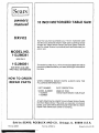
manual
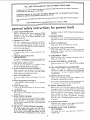
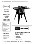
MODEL NO.
113.298341
SAW ONLY
113.298051
SAW WITH LEGS AND
TWO TABLE EXTENSIONS
Serial
Number
Model and serial
number may be found
at the right-hand side
of the base.
CRRFTSMRNo
You should record both
model and serial number
in a safe place for
future use.
10-INCH MOTORIZED
TABLE SAW
CAUTION:
Read GENERAL
and ADDITIONAL
SAFETY
• assembly
INSTRUCTIONS
• operating
carefully
• repair parts
Sold by SEARS,
Part No. 62808
ROEBUCK
AND
CO.,
Chicago,
IL. 60684
U.S.A.
Printed in U,S.A.
FULL ONE YEAR wARRANTY
If within
one year from
the date of purchase,
ON CRAFTSMAN
this Craftsman
TABLE
Table Saw fails due to a defect
workmanship,
Sears will repair it, free of charge.
WARRANTY
OR SERVICE
SERVICE
IS AVAILABLE
CENTER THROUGHOUT
This warranty
gives you specific legal rights, and you may also have other
BY SIMPLY
THE UNITED
SAWS
CONTACTING
STATES.
THE
NEAREST
in material
SEARS
rights which
or
STORE
vary frGm state to
state.
SEARS, ROEBUCK AND CO., Dept. 698/731A SearsTower, Chicago, I L 60684
general
safety instructions for power
1. KNOW YOUR POWER TOOL
Read and understand the owner's manual and labels
affixed
to the tool.
Learn its application
and
limitations
as well as the specific potential hazards
peculiar
to this tool
2. GROUND ALL TOOLS
Th_s tool ss equipped with an approved 3-conductor
co_d and a 3.prong grou_lding type plug to fit the
proper groundir_g type receptacle. The green conductor
m lhe cord is the grounding
wire. Never connect tile
gn!en w.e
to a live terminal.
3. KEEP GUARDS IN PLACE
_n working
order,
and
in
proper
adjustment
and
protectors
operation.
tools
(plugs or muffs) during extended periods of
13. SECURE WORK
Use clamps or a vise to hold work when practical. It's
safer than using your hand. frees both hands to operate
tool.
14. DON'T OVERREACH
Keel) proper footing and balance at all times.
15, MAINTAIN
TOOLS WITH CARE
Keep tools sharl) and clean for best and safest
performance, Follow' instructions for lubricating and
changing accessories,
ahgnmer_t.
4. REMOVE ADJUSTING
AND WRENCHES
16. DISCONNECT
KEYS
Foln_ habit of checking to see Ihat keys and adjusting
wrenches ere removed from tool before turning it o[3.
5. KEEP WORK AREA CLEAN
Clullered
areas and
must not be shppery
benches
,w_te
accidents.
Floor
due Io wax or sawdust.
Don't use power tools in damp or wet IocatLons or
expose them to rain. Keep work area well lighted.
Provide adequate surrounding
work space.
A
VlSltors should
AWAY
_ldr Tel
master
switcnes,
or
uv
Do not store mater=als above or near the tool such that
_ s necessary to stand on the tool to reach them.
at tne rate for which
10. USE RIGHT TOOL
will
to DO alou(
was not
11. WEAR PROPER APPAREL
Do not wear loose clothing, g=oves, necKues or jewelry
Irmqs, wr_st watcnes] to get caught n moving Darts
Nonslio
footwear
is recommenaeo
Wear _rotecttve
nmr covering
to
above the elbow.
Before
furdle_
_s oamageu
was designee
Don't fo_ce tool or atlaahf3ent
oes_gne_ for
conlam
plugging
18. USE RECOMMENDED
ACCESSORIES
Consult
the owner's
manual for recommended
accessories. Follow the instructions that accompany
the accesso_n_s,The use of improper accessories may
cause Itazards,
20 CHECK DAMAGED
and'safer
before
remowng
Keys
DO better
position
in,
STAND
ON TOOL
Serious njury could occur if the tool is tipped or if the
cutting toot Jsaccidentally contacted.
9. DON'T FORCE TOOL
[ Will do the
STARTING
is in "OFF"
from WOrK
8. MAKE WORKSHOP KID-PROOF
_adlocks.
accessories such as
19. NEVER
3e Kep! a safe dlstance
dre;]
w_th
17. AVOID ACCIDENTAL
Make sure switch
6. AVOID DANGEROUS ENVIRONMENT
7. KEEP CHILDREN
TOOLS
before servicing; when changing
blades, bits, cutters, etc,
long ha=r
Roll long
sleeves
a guard
be carefully
properly
for ahgnment
or other
checked
and perform
of moving
its intended
parts,
part that
to ensure that it
binding
function.
of moving
earls,
breakage
con(bt_ons
that
of parts,
mounting,
and any other
may ,affect
its operation.
A guard or
omer 3art
or radiated
is damaged
that
21. DIRECTION
a blade
power
complete
be properly
or cutter
o[ the blade or cutter
22. NEVER LEAVE
UNATTENDED
Turn
should
repaired
OF FEED
Feed WOrK into
of rotation
12. USE SAFETY GOGGLES (Head Protection)
Wear Safety goggles(must comply wJth ANSi Z87.'_
at al t_mes. Everyday eyeglasses omy have mpact
resistant lenses, mev are NOT safety glasses.Also. use
face or dust mask if cutting ooeration is dusty, and ear
use of the tool,
should
c 3erale
Cbeck
PARTS
off.
stop,
TOOL
Don't
against
the direction
only.
RUNNING
leave
tool
until
it comes
to a
ADDITIONAL
SAFETY
INSTRUCTIONS
WARNING:
FOB YOUR OWN SAFETY,
DO NOT
OPERATE YOUR SAW UNTIL IT IS COMPLETELY
ASSEMBLED AND INSTALLED
ACCORDING TO THE
INSTRUCTIONS...AND
UNTIL YOU HAVE
READ
AND UNDERSTAND THE FOLLOWING,
1. GENERAL SAFETY INSTRUCTIONS FOR POWER
TOOLS.,.
SEE PAGE 2
2. GETTING TO KNOW YOUR SAW.,. SEE PAGE 15
3. BASIC SAW OPERATION..,
SEE PAGE 17
4. ADJUSTMENTS...
SEE PAGE 24
5. MAINTENANCE...SEE
PAGE 27
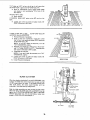
6. STABILITY OF SAW
If there is any tendency for the saw to tip over or move
during certain cutting
operations such as cutting
extremely large heavy panels or long heavy boards, the
saw should be bolted down.
If you attach any kind of table extensions over 24"
wide to either end of the saw, make sure you either bolt
the saw to the bench or floor as appropriate, or support
the outer end of the extension from the bench or floor,
asappropriate.
7. LOCATION
The saw should be positioned so neither the operator
nor a casual observer is forced to stand in line with the
saw blade.
8. KICKBACKS
A "KICKBACK"
occurs during a rip-type operation
when a part or all of the workpiece is thrown back
violently toward the operator.
Keep your face and body to one side of the sawblade,
out of line with a possible "Kickback.'"
Kickbacks - and possible injury from them -- can
usually be avoided by:
A. Maintaining the rip fence parallel to the sawblade.
B. Keeping the sawblade sharp. Replacing antikickback
pawls when points become dull.
C. Keeping sawblade guard, spreader, and antikickback
pawls in place and operating properly. The spreader
must be in alignment with the sawblade and the
pawls must stop a kickback once it has started.
Check their action before ripping.
D. NOT ripping work that is twisted or warped or does
not have a straight edge to guide along the rip fence.
E. NOT releasing work until you have pushed it all the
way past the sawblade.
F. Using a "PUSH STICK" {See Page 18) for ripping
widths of 2 to 6 in., and an auxiliary fence and push
block for ripping widths narrower than 2 in. (See
"Basic Saw Operation
Using The Rip Fence"
section.)
G. NOT confining the cut-off piece when ripping or
crosscutting.
H. When ripping apply the feed force to the section of
the workpiece between the saw blade and the rip
fence.
9, PROTECTION:
EYES, HANDS, FADE, EARS, BODY
A. If any part of your saw is malfunctioning, has been
damaged or broken..,
such as the motor switch, or
other operating control, a safety device or the
power cord.,,
cease operating immediately
until
the particular part is properly repaired or replaced.
B. WRar safety goggles that comply with ANSI Z87.1,
and a face shield if operation is dusty. Wear ear
plugs
or muffs
during extended
periods of
operation.
C. Small loose pieces of wood or other objects that
contact the rear of the revolving blade can be
thrown back at the operator at excessive speed. This
can usually be avoided by keeping the guard and
D,
E,
F_
FOR TABLE
SAWS
spreader
in place for all "THRU-SAWING"
operations (sawing entirely thru the work) AND by
removing all loose pieces from the table with a long
stick of wood IMMEDIATELY
after they are cut
off.
Use extra caution when the guard assembly is
removed
for resawing, dadoing, rabbeting,
or
molding - replace the guard as soon as that
operation is completed.
For rip or rip-type cuts, the following
end of a
workp[ece to which a push stick or push board is
applied must be square (perpendicular to the fence)
in order that feed pressure applied to the workpieee
by the push stick or block does not cause the
workpiece to come away from the fence, and
possibly cause a kickback.
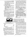
During rip and rip type cuts, the workpiece must be
beld down on the table and against the fence with a
pusb
stick,
push block, or featherboards.
A
featherboard is made of solid lumber per sketch.
I-*
24"-
APART
KERFS
ABOUT
÷1
5/_6 "
I
G. NEVER turn the saw "ON" before clearing the
table of all tools, wood scraps, etc., except the
workpiece and related feed or support devices for
the operation planned.
H. NEVER place your face or body in line with the
cutting tool.
I. NEVER place your fingers or hands in the path of
the sawblade or other cutting tool.
J. NEVER reach in back of the cutting tool with
either hand to hold down or support the workpiece,
remove wood scraps, or for any other reason. Avoid
awkward operations and hand positions where a
sudden slip could cause fingers or hand to move
into a sawblade or other cutting tool.
K. DO NOT perform layout, assembly, or setup work
on the table while the cutting tool is rotating.
L. DO NOT perform any operation "FREEHAND"
always use either the rip fence or the miter gauge to
position and guide the work.
M. NEVER use the rip fence when crosscutting or the
miter gauge when ripping. DO NOT use the rip
fence as a length stop.
Never hold onto or touch the "free end" of the
workpiece or a "free piece" that ls cut off, while
power is "ON" and/or the sawblade is rotating.
N. Shut "OFF" the saw and disconnect the power cord
when removing the table insert, changing the
cutting tool, removing or replacing the blade guard,
or making adjustments.
O. Provide adequate support to the rear and sides of
the saw table for wider or long workpieces.
P, Plastic and composition (like hardboard) materials
may be cut on your saw. However, since these are
usually quite hard and slippery, the antikickbaek
pawls may not stop a kickback.
Q. If you stall or jam the sawblade in the workpiece,
turn saw "OFF", remove the workpiece from the
sawblade, and check to see if the sawblade is
parallel to the miter gauge grooves and if the
spreader is in proper alignment with the sawblade.
If ripping at the time, check to see if the rip fence is
parallel with the sawblade. Readjust as indicated.
R. DONOTremove
smallpieces
of cut-offmaterial
thatmaybecome
trapped
insidetheblade"
guard
whilethesawisrunning.
Thiscouldendanger your
hands or cause a kickback. Turn saw "OFF" and
wait until blade stops.
S. Useextra care when ripping wood that has a twisted
grain or is twisted or bowed - it may rock on the
table and/or pinch the sawblade.
10. KNOW YOUR CUTTING TOOLS
A. Dull, gummy, or improperly sharpened or set
cutting tools can cause materia_ to stick, jam, stall
the saw, or kickback at the operator.
Minimize potential injury by proper cutting tool
and machine maintenance.
NEVER
ATTEMPT
TO FREE A STALLED
SAWBLADE WITHOUT FIRST TURNING THE
SAW OFF.
B, Never use grinding wheels, abrasive cut-off wheels,
friction wheels (metal slitting blades) wire wheels or
buffing wheels.
11. USE ONLY ACCESSORIES DESIGNED FOR THIS
SAW,
12. Crosscuttingoperations are more conveniently worked
and with greater safety if an auxiliary wood facing is
attached to the miter gauge using the holes provided.
However, the facing must not interfere with the proper
functioning of the sawblade guard.
13. Make sure the top of the arbor or cutting tool rotates
toward
you when standing in normal operating
position. Also make sure the cutting tool, arbor collars
and arbor nut are installed properly. Keep the cutting
tool as low as possible for the operation being
performed. Keep all guards in place whenever possible.
WEAR
YOUR
14. Do not use any blade or other cutting tool marked for
an operating speed less than 3450 RPM. Never use a
cutting tool larger in diameter than the diameter for
which the saw was designed. For greatest safety and
efficiency when ripping, use the maximum diameter
blade for which the saw is designed, since under these
conditions the spreader is nearest the blade.
15. Adjust table inserts flush with the table top. NEVER
Operate the saw unless the proper insert is installed.
16. Never feed material into the cutting tool from the rear
of the saw. An accident and serious injury could result.
I7. THINK SAFETY.
Safety is a combination of operator common sense and
alertness at all times when the saw is being used.
18. NOTE AND FOLLOW
SAFETY
INSTRUCTIONS
THAT APPEAR ON THE FRONT OF YOUR SAW.
1.
2.
3.
4.
5.
6.
7.
DANGER
FOR YOUR OWN SAFETY
READ AND UNDERSTAND
OWNER'S MANUAL
BEFORE OPERATING
MACHINE:
WEAR SAFETY GOGGLES PER ANSI Z87.1 ATALl
TIMES
USE SAW-BLADE
GUARD FOR "THRU-SAWlNG"
KEEP HANDS OUT OF PATH OF SAWBLADE
USE A "PUSH-STICK"
WHEN REQUIRED
KNOW HOW TO AVOID "KICKBACKS"
DO NOT PERFORM OPERATIONS
"FREEHAND"
NEVER REACH AROUND OR OVER SAW BLADE
19. WARNING:
DO NOT
ALLOW
FAMILIARITY
(GAINED FROM FREQUENT USE OF YOUR SAW)
TO BECOME
COMMONPLACE
-- ALWAYS
REMEMBER THAT A CARELESS FRACTION OF A
SECOND IS SUFFICIENT
TO INFLICT
SEVERE
INJURY.
20, NOTE; Do not overtighten arbor nut. Use the arbor
wrench to just "snug" it.
The operation of any power tool can result in foreign
objects being thrown into the eyes, which can result in
severe eye damage. Always wear safety gogglescomplying
with ANSI Z87.1 (shown on Package) before commencing
power tool operation. Safety Goggles are available at Sears
retail or catalog stores.
MOTOR SPECIFICATIONS
The AC motor
non-reversible
MOTORSPECIFICATIONS
used in this saw is a capacitor
type. with
the following
MOTOR
from
...............
SAFETY
120
12
60
Single
3450
Counterclockwise
PROTECTION
The saw motor
is equipped with a manual-reset
thermal
overload protector,
designed to open the power line circuit
when the motor temperature exceeds a safe value.
NOTE'. The starting
relay is a GRAVITY
SENSITIVE
TYPE. NEVER TURN THE POWER ON WHILE THE SAW
IS UPSIDE
DOWN
AS THIS
WiLL
DAMAGE
THE
MOTOR
1.
2.
REQUIREMENTS
3.
start,
specifications:
Voltage .................................
Amperes .................................
Hertz
...................................
Phase ................................
RFM ..................................
Rotation {viewe_
Sawblade end)
AND ELECTRICAL
If the protector coons the line and stops the saw motor,
move the saw switch
_ever [o me "OFF"
oosition
immediate y and allow the motor to cool
After cooling
to ] safe operating temperature,
the
overload protector can De closed manually
oy pusniog
_n the red RESET button on the front of the saw. If the
red 3utto_
wdl not snap into place _mmedlately.
the
motor _s stil too hot and must be allowed to cool for a
while longer.
/ks soon as the red button will snap into running
position, the saw may be started and operated normally
by moving the saw switch lever to the "ON" position,
4. Frequent opening of fuses or circuit breakers may result
if motor is overloaded, or if the motor circuit is fused
with a fuse other than those recommended, Do not use
a fuse of greater capacity without consulting the power
company,
5. Although the motor is designed for operation on the
voltage and frequency specified on motor nameplate,
normal loads will be handled safely on voltages not
more than 10% above or below the maneplate voltage.
Heavy loads, however, require that voltage at motor
terminals by not less than the voltage specified on
nameplate.
6, Most motor
troubles may be traced to loose or
incorrect
connections,
overloading, reduced input
voltage (which results when small size wires are used in
the supply circuit) or when the supply circuit is
extremely long. Always check connection,
load and
supply circuit
when the motor fails to perform
satisfactorily. Check wire sizes and lengths with table at
end of this section.
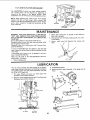
CONNECTING
TO POWER SOURCE OUTLET
This saw must be grounded while
operator from electrical shock.
in use to protect the
If power cord is worn or cut, or damaged in any way, have
it replaced immediately.
This plug requires a mating 3.conductor
outlet as shown.
If your saw is for use on lessthan 150 volts it has a plug
that looks like below.
If the outlet you are planning to use for this saw is of the
two prong type DO NOT REMOVE OR ALTER THE
GROUNDING PRONG IN ANY MANNER. Use an adapter
as shown and always connect the grounding lug to a known
ground.
It is recommended that you have a qualified electrician
replace the TWO prong outlet with a properly grounded
THREE prong outlet.
3-P_ONG
PLUG
e
GROUNDING
type
PRONG
GROUNDED
3-FRONG
grounded
OUTLET
Plug power cord into 110-120V properly grounded type
outlet protected by a 15-amp. time delay or Circuit*Saver
fuse or circuit breaker.
IF YOU ARE NOT SURE THAT YOUR OUTLET
IS
PROPERLY GROUNDED,
HAVE IT CHECKED BY A
QUALIFIED ELECTRICIAN.
WARNING:
DO NOT PERMIT FINGERS TO TOUCH
THE TERMINALS
OF PLUG WHEN INSTALLING
OR
REMOVING THE PLUG TO OR FROM THE OUTLET.
WARNING:
IF NOT PROPERLY GROUNDED
THIS
POWER TOOL CAN INCUR THE POTENTIAL HAZARD
OF ELECTRICAL
SHOCK, PARTICULARLY
WHEN
USED IN DAMP LOCATIONS;
IN PROXIMITY
TO
PLUMBING, OR OUT OF DOORS. IF AN ELECTRICAL
SHOCK OCCURS THERE IS THE POTENTIAL
OF A
SECONDARY
HAZARD
SUCH AS YOUR HANDS
CONTACTING THE SAWBLADE.
This saw is equipped with a 3-conductor cord and
grounding type plug which hasa grounding prong, approved
by Underwriters' Laboratories and the Canadian Standards
Association. The ground conductor has a green lug and is
attached tothe tool housing at one end and to the ground
prong in the attachment plug at the other end,
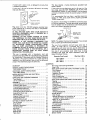
WARRANTY .......................................
GENERAL SAFETY INSTRUCTIONS
FOR POWER TOOLS ..............................
ADDITIONAL SAFETY INSTRUCTIONS
FOR TABLE SAWS ................................
MOTOR SPECIFICATIONS AND ELECTRICAL
REQUIREMENTS ..................................
UNPACKING AND CHECKING CONTENTS ...........
Tools Needed .....................................
List of Loose Parts ................................
ASSEMBLY
.......................................
Installing Elevation and Tilt Handwheels ............
Checking Table Insert .............................
Checking Blade Squareness to Table ...............
Checking Blade Elevation ..........................
Attaching Table Extensions ........................
Instarling Rip Fence Guide Bars ....................
Assembling Steel Legs ..........................
Mounting Saw .................................
Aligning Table Extensions .......................
Aligning Rip Fence ..............................
Installing Blade Guard ..........................
GETTING TO KNOW YOUR SAW ..................
On-Off Switch ..................................
Reset Button ...........
, .......................
Elevation Handwheel ............................
Tilt Hendwheel
.................................
Rip Fence ......................................
Miter Gauge ....................................
Blade Guard ....................................
Table Insert ....................................
An adapter asshown below is available for connecting plugs
to 2.prong receptacles. The green grounding lug extending
from the adapter must be connected to a permanent ground
such as to a properly grounded outlet box.
GRIDUNblN C LUG
NOTE: The adapter illustrated is for use only if you already
have a properly grounded 2-prong receptacle,
The use of any extension cord will cause some loss of
power. To keep this to a minimum and to prevent
over-heating and motor burn-out, use the table below to
determine the minimum wire size (A.W.G.) extension cord.
Use only 3 wire extension cords which have 3 prong
grounding type plugs and 3-pole receptacles which will
accept the plug o_ the saw.
Extension Cord Length
Upto 10OFt ......................
100-200 Ft .......................
200-400
Ft ........................
Wire Size A.W.G.
12
10
8
CONTENTS
2
Removing and Instalfing Sawblade ...............
Exact-l-Cut ......
, .........................
BASIC SAW OPERATION USING THE MITER GUAGE
2
Work Helpers ...................................
Crosscutting ....................................
3
Repetitive Cutting ...............................
Miter Cutting ...................................
4
Bevel Crosscutting ..............................
6
Compound Miter Cutting ........................
6
BASIC SAW OPERATION USING THE RIP FENCE ..
6
Ripping ........................................
7
Bevel Ripping
..................................
7
Resawing ......................................
7
Cutting Panels ..................................
8
Ploughing and Molding ........................
8
Rabbeting ......................................
8
Dadoing ........................................
9
Using Featherboards ..........................
10
ADJUSTMENTS'.
.................................
10
Miter Gauge ....................................
11
Heeling Adjustment or Parallelism of
11
Sawblede to Miter Gauge Groove ...............
13
Blade Tilt, or Squareness of
15
Blade to Table .................................
15
Blade Elevation .................................
16
Tilt and Elevation Mechanism
..................
16
MAINTENANCE ..................................
16
LUBRICATION ...................................
16
TROUBLESHOOTING ..........................
16
RECOMMENDED ACCESSORIES ................
16
16
REPAIR PARTS ..................................
16
17
17
18
18
19
20
20
20
20
21
21
22
22
23
23
23
24
24
24
24
25
26
27
27
27
28
29
30
UNPACKING
AND
CHECKING
WARNING:
FOR
YOUR
OWN SAFETY,
NEVER
CONNECT PLUG TO POWER SOURCE OUTLET UNTIL
ALL ASSEMBLY STEPS ARE COMPLETE, AND YOU
HAVE READ AND UNDERSTAND
THE SAFETY AND
OPERATIONAL INSTRUCTIONS.
NEED_
Hamrnel
CONTENTS
Medium Screwdriver
Small Screwdriver
LIST
#2
i;ili_
Philip Screwdriver
....• ,-
i
I
318in. 7116in.
1/2 in.
COMBINATION
StrAIGHT
LIGHt
LIN[
ALONG
in.
SQUARE MUST BE TRUE.
3/4
D_AW
9ftfi
314in.
CombinationSquare
BOA_D
A
B
C
D
E
F
G
H
J
K
Wrenches
liers
EDGE
THICK.
ON
8OARO
THIS EDGE _UST
BE _ERFECIL¥
THIS EDGE.
OF
ST_AfGHT*
"_\
\
SHOULD
BE NO
GAP
_[R[
,",HEN
_QUAR£
OVER
IN
DOTTED
L
M
N
P
P
Q
S
T
X
_R OVERLAP
IS FLIPPED
POSI$1ON,
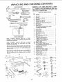
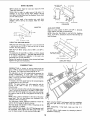
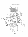
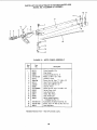
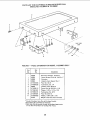
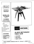
Model
113,298051 Motorized Table Saw is shipped
complete in one carton but INCLUDES TWO Table
Extensionsand Steel Legs.
Separate all parts from packing materials and check each
one with the illustration and the list of Loose Parts to make
certain all items are accounted for, before discarding any
packing material.
If any parts are missing, do not a_tempt to assemble the
table saw. plug in the power card or torn the switch on
until the missing parts are obtained and ere installed
correctly.
B
/
I;'/
J
.... ___
1
C
D
F
j
H
PARTS
G
6
Oty.
Miter Gauge ..............................
Rip Fence ...............................
BladeGuardandSpreader ...................
Haedwheel ...............................
Rip FenceGuide Bar, Rear ..................
Rip FenceGuide BarRod ...................
Rip FenceGuide Barwith Rip Scale(Front) .....
Arbor Wrench ............................
Arbor Nut Wrench .........................
OwnersManual ...........................
Bagof MisceJlaneous
SmallParts No. 62807
Consistingof the following:
SpreaderSupport ..........................
SpreaderClamp ...........................
SpreaderBracket ..........................
SetscrewWrench,1/8 in....................
SetscrewWrench,3/16 in....................
Switch Key ..............................
See.Hd. Set Screw 1/4-20 x 7/8 ..............
SquareNut, 1/4-20 ........................
Loekwasher #'10 ExternalType
(approx.dia. of hole3/1B in.) ...............
X Leckwasher,1/4 in. ExternalType
(approx,dia. of hole1/4 in.) ................
Y WingNut 1/4-20 ..........................
AA Screw, PanHd. 10-32 x 3/4 ..................
BB Truss HeadScrew, 1/4-20 x 5/8 long ...........
Pkg.of Miscellaneous
SmallPartsNo. 62768
Consisting
of the Following:
R GuideBarSpacer ..........................
U Self ThreadingNut .........................
V Flatwasher,(dia.of hole17/64in.) ............
V Flatwasher,(dia. of hole 21/64 in.) ............
V Flatwasher,17/64 x 5/8 x 1/16 ...............
W Hex Nut, 1/4-20
(Approx. die. of hole 1/4 in.) ...............
W Hex Nut, 5/16-18
(approx. dia. of hole5/16 in.) ...............
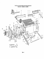
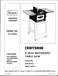
Model 113.298341
Motorized Table Saw is shipped
complete in one carton but DOES NOT INCLUDE Table
Extensions and Steel Legs.
_
OF LOOSE
Key
No. PartName
1
1
1
2
1
1
1
1
1
1
..
1
1
1
1
1
1
2
2
2
2
2
2
2
2
2
4
4
8
6
4
X
X
Z
Z
BB
LookwaEher,
1/4 in. ExternalType
(approx. dia. of hole 1/4 in.) ................
Lookwasher,5/16 in. ExternalType
(approx. dia. of hole 5/16 in.) ...............
Hex Hd. Screw,5/16-18 x 1-1/2 in. long ........
HaxHd. Screw,5/16.18xlin,
long ...........
Truss HeadScrew, 1/4-20 x 5/8 ...............
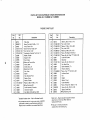
The following
8
4
2
2
4
parts are included with Model 113.298051
Key
No. PartName
A
B
C
D
F
G
G
J
K
E
F
C
0.ty.
Leg .....................................
4
Side Stiffener ..............................
2
End Stiffener .............................
' 2
Table Extension ...........................
2
Pkg.of Miscellaneous
Small Parts,No. 62767for Legs
Consisting
of the Following:
Lnckwasher,1/4 in. ExternalType
(approx.dia. of hole 1/4 in.) ................
24
Hex Nut, 1/4-20
(approx.dia. of hole 1/4 in.) ................
24
Hex Nut, 1/2-13
(approx.dia. of hole 1/2 in.) ................
8
TrussHeadScrew, 1/4-20 x 5/8 in.long
(top of screwis rounded) ..................
24
Leveling Foot .............................
4
Pkg. of Miscellaneous
Small PartsNo. 62745 for
Table ExtenEions,Two Each:
Consistingof the Following'.
Hex Head Screw5f16-18 x 1-1/4 ..............
8
LockwaEher,5/1B in. ExternalType
(approx.dia. of hole 5/16 in.) ...............
8
F
Lockwaeher,1/4 in, External Type
(approx.dia. of hole 1/4 in.) ................
Hex Nut, 5/16-18
(approx.dia. of hole5/16 in.) ...............
Hex Nut, 1/4-20
(approx.dia. of hole1/4 in.) ................
FlatWasher(dia. of hole 11/32) ..............
FlatWasher(dia. of hole 17/64) ..............
TrussHeadScrew, 1/4-20 x 1in. long
(top of screwis rounded) ..................
CornerStiffener Bracket ....................
CornerSupport Bracket .....................
G
G
H
H
J
L
M
1B
8
1B
8
4
1B
4
4
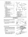
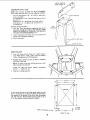
ASSEMBLY
Before mounting the saw on legs,a stand or a bench, the
Table Insert and Blade Squareness and Blade Elevation
must be checked at this time.
LOCKWASHER
INSTALLING
1.
ELEVATION
AND TILT
LOCKWASHER
HANDWHEELS
Line up FLAT SPOTS on shaft and handwheel, push
handwheel onto shaft. Install screw and Iockwasher to
lock hendwheel on shaft,
SCREW
EILT
SCREW
HANDWHEEL
EL[VATION
HAKIDWHEEL
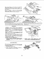
CHECKING TABLE INSERT
1. With the insert in place, and sawblade all the way down,
use a small scale or straight edge to check near each of
the eight leveling tab positions, in order to determine if
the insert is flush with saw table surface at aPIeight tab
locations.
2.
If the insert is above the table surface, the leveling tabs
must be adjusted.
A.
B.
Loosen Screw.
Lift
insert
from
front
end, and pull toward
front
of
saw.
C.
Remove the insert, place it upside down on your
workbench
and GENTLY
TAP each of the tabs
downward
only a slight amount.
Replace insert...
check it and readjust tabs, if necessary.
__;
LEVELING
TAB
3.
If the
insert is BELOW
the table surface,
insert and bend the tabs (with pliers)
the insert ABOVE the table surface.
4.
To replace
remove
enough
the
to make
insert.
Place insert into
insert opening in table
toward
rear of saw to engage spring clip
keyslot in insert will drop over screw. Tighten
and push
and until
screw.
DO NOT TIGHTEN SCREW TO THE POINT WHERE IT
DEFLECTS THE INSERT.
CHECKING BLADE SQUARENESS TO TABLE
IMPORTANT:
BLADE must be SQUARE (90° ) to
TABLE, in order to proceed with assembly.
To check for blade squareness, refer to "BLADE TELT, OR
SQUARENESS OF BLADE TO TABLE" adjustments on
page 25.
NOTE: The Combination Square must be "TRUE" - See
start of "Unpacking and Checking Contents section on page
6 for checking method.
CHECKING BLADE FOR HEEL
IMPORTANT: Saw blade MUST be parallel to miter gauge
groove.
To check
for
parallelism,
refer
to "HEELING
ADJUSTMENT OR PARALLELISM OF BAWBLADE TO
MITER GAUGE GROOVE" adjustment on page24.
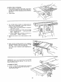
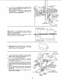
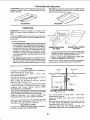
CHECKING BLADE ELEVATION
Maximum depth of cut MUST NOT EXCEED TWO AND
ONE HALF (2-1/2 INCHES. This adiustment is set at the
factory and should be checked to make sure that it has not
changed due to rough handling during shipment.
ATTACHING
\
With the blade up as high as it will go, measure the distance
from the top of the table to top of the highest saw tooth. If
it is more than two and one half (2-1/2) inches, adjust it at
this time. Refer to "BLADE ELEVATION"
adjustments on
page 26.
saw
and
1. Position saw upside down on floor.
NOTE'. To protect the finished surfaces of the saw and
extensions, lay e piece of heavy paper on the floor.
2, From among the loose parts find the two loose parts
bagsfor table extensions.
B Hex Head Screws 5/16-18 x 1¼ in. long
8 Lockwashers, 5/16 in. External Type
(approx. dia. of hole 5/16 in.)
8 Flat Washers (dia. of hole 11/32 in.)
8 Hex Nuts, 5116-18 (approx. dia. of hole 5/16 in.)
16 truss head screws 1/4-20 x 1
4 corner support brackets
4 corner stiffener brackets
16 Hex nut 1/4-20
16 !ockwashers, 1/4" External Type
4 Flat Washers (Dia. of hole 17/64)
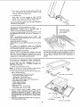
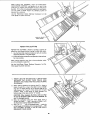
4.
\
AND ASSEMBLING TABLE EXTENSIONS
If you received two Table Extensions with your
(furnished with Model No. 113.296051)assemble
attach them at this time.
3.
MAKE SURE SQUARE
IS NOT TOUCHING
TIP OF TOOTH
Install
support
corner brackets, stiffener corner
brackets, screws, Ioekwashers, washers, and nuts for
assembling extensions as shown...tighten
screws
attaching extensions to tabre SNUGLY. BE SURE END
OF EXTENSIONS ARE EVEN WITH FRONT EDGE
OF SAW.
Leave saw in upside down position until you attach the
rip fence guide bars and legs,
/_e_
/
17/64 DIA. FLAT WASHER
f
FLAT WASHER
LOCKWASHER
5/16-18 x 1-1/4
SCREW
EXT. LOCI<WASHER
5/16 IN,
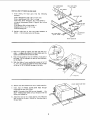
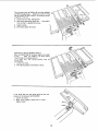
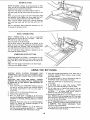
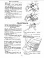
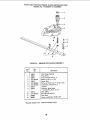
INSTALLING
1,
_
RIP FENCE GUIDE BARS
From
among
hardware:
the
loose
parts
find
the
following
HEX, HEAD SCREW
I IN, LONG
FLAT WASHER
HEX NUT
5/16 IN.
REAR GUIDE BAR
2 Hex. Head Screws, 5/16 - 18 x 1-1/2 in. long
2 Hex. Head Screws, 5/16 - 18 x 1 in. long
4 Hex. Nuts, 5/16 - 18 (approx. dia. of hole 5/16 in.)
4 External Lockwashers, 5/16 in. (approx. dia. of hole
5/16 in.)
4 Flat Washers (Dia. of hole 21/64 in.)
2 Spacers, 3/4 in. dia. x 1/2 in. long
2 Self-threading nuts
2.
Position guide bars on floor and install hardware
shown..,
do not screw nuts on all the way.
as
FRONT GUIDE aAR
3.
Place front guide bar against saw table and drop it in
place ... engaging the screws in the slots. Make sure the
spacersare between the rail and the table.
4.
End of front guide bar must be 7-5/16 in. from side of
saw table. This is important so that rip fence Indicator
can be aligned.
5.
With the blade of your combination square set to 1/4
in., use it as a gauge and attach the rail so that the edge
of the rail is 1/4 in. ABOVE the edge of the table.
/_
7-5/16
IN,
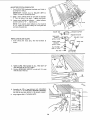
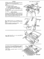
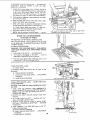
FENCE GUIDE BAP,ROD
6.
Remove
7.
Insert
round
the three
screws from
ends of FENCE
GUIDE
holes at outer end ef bars.
rear of table
BAR
ROD
extension,
through
NOTE: The ends of the ROD are not threaded
... the
SELF THREADING
NUTS will cut threads on the rod
as they are'screwed
8.
on.
Attach the rear bar in a similar manner, but make sure
that the end of the bar is 10-9/16 in. from the side of
the saw table.
SCREWS THROUGH
HOLESMARKED"X"
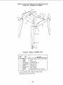
ASSEMBLING STEEL LEGS
NOTE'. Steel Legs are furnished with Model 113.298050.
From among the loose parts, find the following Hardware'.
24 Truss Head Screws, 1/4 -- 2Q x 5/8 in. long (top of
screw is rounded)
24 Lockwashers, 1/4 in. External Type (approx. dia. of
hole 1/4 in.)
24 Hex Nuts, 1/4 - 20 (approx. dia. of hole 1/4 in.)
8 Hex Nuts. 1/2 - 13 (approx. dia. of hole 1/2 in.)
4 Leveling feet.
Assemble the legs as shown ...
1. Insert the Truss Head Screws through the holes in the
legs, then through the holes in the stiffeners. MAKE
SURE THE SCREWS GO THROUGH THE HOLES IN
THE SIDE STIFFENERS MARKED "X".
2.
3.
Install
Iockwashers
tighten
until
Install
and screw on the nuts
completely
SIDE STIFFENER
END
STIFFENER "_
but do not
assembled.
leveling feet.
HEX
_,_.-----_-
NUTS
LEVELING FOOT
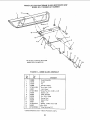
MOUNTI NG SAW
1. From the loose parts find the four 1/4-20 x 5/8 in.
Truss Head Screws, 17/64 x 5/8 x 1/16 Flat Washers,
1t4 in. Lockwashers and 1/4-20 Hex Nuts.
2.
FRONT
Positior_ legs as shown and line up holes in stiffeners
with holes _n saw base,
NOTE: At front of saw you will see four holes, insert
bolts through holes as shown.
3.
Attach
legs using
and nuts..,
tighten
the screws,
the nuts.
Place saw it] upright
position.
washers,
Iockwashers
REAR
I
•
If you mount the saw on anv other bench, make sure that
there is an opening in the top of the bench the same size as
the opening in the bottom of the saw so that the sawdust
can drop through. Recommended working height is 33 to
37 in. from the top of the saw table to the floor.
4 HOLES
7/16 [_IA.
FRONTOF SAW
ALIGNING
TABLE EXTENSIONS
1. "Tap" extensions upwards or downwards, using a block
of wood and a hammer until they are even with top of
saw table. Be sure end of extensions are even with front
edge of saw.
2.
Tighten screws.
3.
Lay a straight piece of wood or a framing square on
table tp act as a straightedge. If outer edge of extension
is higher or lower than table surface:
A. Slightly loosen nuts holding bracket to extension
using 7/16 in. wrench.
B. Move end of extension up or down until outer edge
is even with table surface . . . check with GUIDE
BAR ... tighten nuts.
C. Recheck INNER edge of extension to make sure it
has not moved.., readjust, if necessary.
4.
Replace three screws in rear of table extension on right
side.
5_
BLOCK OF WOOC
Hold rod with one hand and with a 1/2 in. wrench or
pliers start screwing on ONE of the nuts only A TURN
OR TWO...
screw on other nut the same way.
Using TWO 1/2 in. wrenches or pliers tighten both of
the nuts.
F
IMPORTANT:
Apply a coat of paste wax to the top surface
and front edge of the front guide bar. This will allow the
fence to slide more easily.
ALIGNING
6.
RIP FENCE
Position rip fence over miter gauge groove, holding up
the rear end while engaging front end with bar . . .
lower fence onto table.
t!
HEX SCREWS_
The rip fence must be PARALLEL
with the sawblade
and Miter Gauge grooves. ,. Move fence until it is along
side of groove. Do NOT LOCK IT. It should be parallel
to groove. If it is not;
A.
Loosen
B.
Hold fence head tightly against bar..,
fence so that it is parallel with groove.
the two
"Hex.
Head Screws."
C.
Tighten
D.
A_ternately
move end of
handle.
tighten
the screws.
Place fence on saw but DO NOT
LOCK
IT.
Move the REAR END of the fence slightly to the right
or left . . . when you release it, the fence should
"spring"
beck to its original position.
If
it
does
INCREASED,
1.
Loosen
2.
Move Spring
not,
the
spring
pressure
must
be
the screws.
slightly toward
front
of fence.
If the fence does not slide easily along
pressure of the spring can be REDUCED,
1.
Loosen the screws.
2.
Move spring slightly
tighten screws.
toward
rear
the
of
bars, the
fence
. , .
SPRING
12
ADJUSTING
RIP SCALE INDICATOR
1. Turn ELEVATION
handwheel clockwise until blade is
up as high as it will go.
IMPORTANT'.
BLADE must be SQUARE
TABLE, in order to ALIGN rip fence.
(90 o) to
2.
Using a ruler, position fence on right side of sawblade
2" from the sides of the teeth..,
tighten lock knob.
3.
Loosen screw holding the indlcator.., adjust indicator
so that it points to "2"...
tighten screw.
LOCK
KNOB
NOTE: If you cannot adjust indicator so that it points
to "2", loosen the screws holding the front guide bar
and move the guide bar.
SPREADER BRACKET
TRUSSHEAD
_'-',
SCREW -----,,-_
INSTALLING
1.
_'_,_"'_,_"
From among the loose parts, find the hardware as
shown.
SOCKETHEAD
_1
SETSCREW
7/8iN. LONG
<m
FLATIN.
WASHER__
17/64
HOLE
HEX NUT"-"_ _
2.
3.
SPREADER CLAMP
BLADE GUARD
MAKE SURE THE BLADE IS ALL THE WAY UP
AND SQUARE WITH THE TABLE.
Position SPREADER SUPPORT on rod until it is even
with the end of the rod.
4.
Assemble the 7/8 in. long setscrews, nuts, Iockwashers
and washers to the SPREADER SUPPORT BRACKET
and slip the nuts into the slot in the spreader support,
5.
Finger tighten ONLY THE HEX NUTS.
BLADE SQUARE
WITH TABLE
13
_lf
I
WING NUT
/
/
@-.
_
LOCKWASHER
EXT. I/4 IN.
6.
Lay a piece of flat straight wood and a square on saw
table and rotate the SPREADER SUPPORT until the
bracket is aligned with square.
7. MAKE SURE END OF SUPPORT, BRACKET AND
ROD ARE EVEN . .. usingan I18 in. setscrewwrench,
TIGHTEN THE SET SCREWS ONLY.
ENDS OF SUPPORT
AND BRACKET TO
RE EVEN WITH
END OF ROD
TIGHTEN
SETSCREWONLY
SPACE
EQUAL
3 THICKNESSES
IMPORTANT:
PARALLEL
(KERF)
The
SPREADER
must
to the sawblade and in the MIDDLE
TO
APPROX,
OF
PAPER
WOOD
BLADE
always be
of the cut
made by the sawblade.
NOTE: The spreader is thinner than the width
by approximately
six thicknesses of paper.
of the KERF
SPACE EQUAL TO APPROX.
3 THICKNESSES OF PAPER
8.
KERF
LOOKING
DOWN
ON
SAW
Make two folds in a small piece (6 x 6 in.) of ordinary
NEWSPAPER making three thicknesses. The folded
paper will be used as a "spacing gauge".
ANTIKICKBACK
PAWLS
g. Install the SPREADER CLAMP. Place spreader between
spreader clamp and bracket. Move forward until all
three are in line, TIGHTEN WING NUTS.
PIECE OF
STRAIGHT WOOD
IGHTLY AGAINST
HOLD
WOOD
BLADE
10. Lift up both ANTIKICKBACK
PAWLS...
insert one
of the setscrew wrenches or a pencil in the notches to
hold the pawls out of the way.
1
THREE
THICKNESSES
OF PAPER
11. Lay a piece of straight flat wood against the sawblade.
Insert folded paper between spreader and strip of wood.
12. MAKE SURE THE HEX NUTS UNDERNEATH ARE
LOOSE.
13. Hold the spreader tightly against the wood and make
sure the wood is against the saw blade. TIGHTEN THE
HEX NUTS.
This will align the spreader in the middle of the cut
(KERF) made by sawblade.
WING NUT
HOLD SPREADER
TIGHTLY AGAINST WOOD
SPREADER
SPREADER BRACKET
CLAMP
14
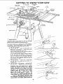
GETTING
MITER GAUGR
LOCK KNOB
7
TO KNOW
BLADE GUARD
MfIER GAUGE
6
MITER GAUGE
YOUR SAW
ANTIK[CKBACK
PAWLS
9 SAW
aLADE
SPREADER
HEAD
\
I TABLE INSERT
4
HOLES FOR
ATTACHING
FAGLNG
TILT HANDWHEEL
3 ELEVATION HANDW}
I
ON-OFF
SWITCH !
_L
] ON-OFF SWITCH
11
CAUTION: Before turning switch on, make sure the blade
guard is correctly installed and operating properly.
@
The On-Off Switch has a locking feature. THIS SHOULD
PREVENT
UNAUTHORIZED
AND
POSSIBLY
HAZARDOUS USE BY CHILDREN AND OTHERS.
A. Insert key into switch.
B. TO turn saw ON .,. stand to either side of the
blade never in line with it ... insert finger under
switch lever and pull END of lever out.
After turning switch ON, always allow the blade to
come up to full speed before cutting.
Do not cycle the motor switch on and off rapidly,
as this may cause the sawblade to loosen, in the
event this should ever occur, allow the sawblade to
come to a complete stop end retighten the arbor
nut normally,
not excessively. Never leave the saw
while the power is "ON".
C. TO turn saw OFF ... PUSH bver in. Never leave
the saw until the cutting tool has come to a
complete stop.
D. TO lock switch in OFF position..,
hold switch IN
with one hand...
REMOVE key with other hand.
KEY
ON-OFF
WARNING:
FOR YOUR OWN SAFETY, LOWER
BLADE OR OTHER CUTTING TOOL BELOW
TABLE
SURFACE.
(IF BLADE IS TILTED,
RETURN IT TO VERTICAL (90° ) POSITION).
ALWAYS LOCK THE SWITCH "OFF".
WHEN
SAW IS NOT IN USE .., REMOVE KEY AND
KEEP IT IN A SAFE PLACE ... ALSO ... IN
THE EVENT OF A POWER FAILURE (ALL OF
YOUR LIGHTS GO OUT) TURN SWITCH OFF
... LOCK IT AND REMOVE THE KEY. THIS
WILL PREVENT THE SAW FROM STARTING UP
AGAIN WHEN THE POWER COMES BACK ON.
15
SWSTCH
KEY
(YELLOW PLASTIC)
'_
3
NOTE: When bevel crosscutting, attach facing so that it
extends to the right of the miter gauge and use the miter
gaugein the groove to the right of the blade.
RESET BUTTON ... See "Motor Specifications and
Electrical
Requirements" section, "Motor
Safety
Protection."
ELEVATION HANDWHEEL...
elevatesor lowers the
blade. Turn clockwise to elevate ... counterclockwise
to lower.
NOTE: WHEN THE BLADE IS TILTED TO 45 ° , IT
CANNOT BE LOWERED ALL THE WAY BELOW
THE TABLE. IT WILL PROJECT APPROX. 1/2 IN.
4
RY FACING
TILT HANDWHEEL
...
tilts the blade for bevel
cutting.
Turn clockwise to tilt toward left ...
counterclockwise to tilt toward right.
7
BLAOEGUARD must always be in place and working
properly for all thru-sawing cuts. That is, all cuts
whereby the blade cuts completely through the
workplace.
To remove the guard for special operations, loosen the
wingscrewsand move spreader away from saw and lift
upwards. DO NOT DISTURB THE SETTING OF THE
HEX NUTS.
When replacing the guard, make sure the spreader is
moved toward front of saw so that wingscrews are at
end of slots.
TIGHTEN
THE
WlNGSCREWS
SECURELY.
8
TABLE INSERT is removable for removing or installing
bladesor other cutting tools..
When the blade is tilted to the LEFT as far as it will go,
it should be at 45 ° to the table and the bevel pointer
should point 45 °,
NOTE: Tbe_e are LIMIT STOPS inside the saw which
prevent the blade from tilting beyond45 ° to the LEFT
and 90° to the RIGHT. (._ee "Adjustments"
section
"Blade Tilt, or Squarenessof Blade to Table").
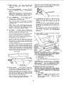
5
RIP FENCE ... is locked in place by tfghtening the
lock knob. To move the fence, loosen the lock knob
and grasp the fence with one hand at the front.
Holes are provided in the rip fence for attaching a wood
facing when usingthe dido head, or molding head.
Select a piece of smooth straight wood approx. 3/4 in.
thick and the same size as the rip fence.
PAWLS
ANTIKICKBACK
/
Attach it to the fence with three Round Head # 10
Wood Screws 2 in. long. To remove the facing, loosen
the screws, slide the facing forward and pull the screws
through the round holes.
If you are making a rip type cut in material thinner
than 3/16 in. while the fence is positioned over the
depressed area of table extension, the facing should be
attached to the fence so that the bottom edge touches
the top surface of the extension. In this case, the facing
must be shorter than the fence. This will prevent thin
material from sliding under the rip fence.
WOOD
SCREW
FACING
\
WARNING: FOR YOUR OWN SAFETY, TURN SWITCH
"OFF" AND REMOVE PLUG FROM POWER SOURCE
OUTLET BEFORE REMOVING INSERT.
A. Lower the blade below the table surface.
B. Loosenscrew.
C. Lift antikickback pawls.
D. Lift insert from front end, and pull toward front of
saw,
_________-----_--
NEVER OPERATE THE SAW WITHOUT THE PROPER
INSERT IN PLACE. USE THE SAW BLADE INSERT
WHEN SAWING ... USE THE COMBINATION
DADO
MOLDING INSERT WHEN DADOING OR MOLDING.
ROUND HEAD J
_'1o WOOD SCREWS
6
9
MITER GAUGE . . . head is locked in position for
crosscutting or mitering by tightening the lock knob.
ALWAYS LOCK IT SECURELY WHEN IN USE.
SAWBLADE
WARNING: FOR YOUR OWN SAFETY, TURN SWITCH
"OFF" AND REMOVE PLUG FROM POWER SOURCE
OUTLET
BEFORE
REMOVING
OR INSTALLING
SAWBLADE:
Notches are provided in the miter gauge for attaching
an AUXILIARY
FACING to make it easier to cut ]ong
pieces. Be positive facing does not interfere with the
proper operation of the sawblada guard.
Select a suitable piece of smooth straight wood..,
two holes through it and attach it with screws,
REMOVING AND INSTALLING
A. Remove insert.
B, Place ARBOR wrench on flat surfaces of saw
ARBOR ; . , ARBOR NUT wrench on nut . ..
position wrenches as shown . . . hold your hands
well above blade.
drill
16
C. With ARBOR wrench against table, PULL ARBOR
NUT wrench FOREWARD to LOOSEN nut.
D. To TIGHTEN nut . . . HOLD ARBOR wrench
against rear of table . . . PUSH ARBOR NUT
wrench toward rear.
Do not tighten screw to the point where it will
deflect the insert.
10 EXACT-I-CUT
The "yellow" plastic disc _mbedded in the tabte in front
of the sawblade, is provided for marking the location of
the "sawcut" on the workpiece.
A. Check disc, o. if it is above table surface, place a
piece of hardwood on top of it and tap it down.
B, With blade 90 ° (square to table} cut off a piece of
wood.
NOTE: When installlng the blade . . . make sure the
teeth are pointing toward the fiont of the saw ... and
that the blade and collars are clean, and free from any
burrs.
The HOLLOW
blade,
side of the collars must be against the
C. Pull miter gauge back until wood isover disc, Using
very sharp pencil, mark a line on disc.
D. With miter gauge in right hand groove, followsame
procedure and mark another line on disc.
E. These lines indicate the "path" of the cut (kerr)
made by the sawblade.
F. When cutting the workpiece, line up mark on
workplace with line on disc.
Always tighten the arbor nut securely.
NOTE: Do not overtighten
wrench to just "snug" it.
E. To replace insert.
arbor nut. Use the arbor
Place insert into insert opening in table and push
toward rear of saw until keyslot in insert will drop
over screw. Tighten screw.
PULL
ro LOOSE_
__ARBOR
PUSH TO_TIGHIr EN
BLADE GUARD NOT
SHOWN FOR PICTURE CLARITY
HEX NUT
TEETH POnqTING
FRONT OF SAW
TO_
\
1
_.
_._
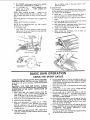
BASIC SAW OPERATION
USING THE MITER
CROSSCUTTING, MITER CUTTING, BEVEL CUTTING,
COMPOUND MITER CUTTING and when RABBETING
across the end of narrow workpiece, THE MITER GAUGE
IS USED.
WARNING:
FOR YOUR OWN SAFETY,
ALWAYS
OBSERVE THE FOLLOWING SAFETY PRECAUTIONS
IN ADDITION
TO THE SAFETY INSTRUCTIONS ON
PAGES 2,3, and 4.
1. Never make, these cuts freehand (without using the
miter gauge or other auxiliary devices) bebause the
blade could bind in the cut and causea KICKBACK or
causeyour fingers or hand to slip into the blade.
2. Always lock the miter gaugesecurely when in use.
3. Remove rip fence from table.
4. Make sure blade guard is installed for all "THRUSAWING" operations
(when sawblade cuts entirely
thru the thickness of the workpiece.) Replace guard
IMMEDIATELY
after completion of dadoing, molding
or rabbeting cuts.
5. Have blade extend approximately 1/8 in. above top of
workpiece. Additional
blade exposure would increase
the hazard potential.
GAUGE
6.
Do not stand direcUy in front of the blade in case of a
THROWBACK (Small cut-off piece caught by the back
of the blade and thrown toward the operator). Stand to
either side of the blade,
7.
Keep your hands clear of the blade and out of the path
of the blade.
If blade stalls or stops while cutting', TURN SWITCH
OFF before attempting to free the blade.
Oo not reach over or behind the blade to pull the
workpiece through the cut..,
to support long or heavy
workpieces . , . to remove cut-off pieces of material or
FOR ANY OTHER REASON,
8.
9.
10. DO not pick up small pieces of cut-off material from the
table. REMOVE them by pushing them OFF the table
with a long stick. Otherwise they could be thrown back
at you by the rear of the blade.
11, Do not remove small pieces of cut-off material that may
become TRAPPED insid_ the blade guard while the saw
is RUNNING,
THIS COULO ENDANGER
YOUR
HANDS or cause a KICKBACK.
17
Turn the saw OFF, After the blade has stopped turning,
llft the guard and remove the piece.
rHESE EDGES MUS] r
BE P/_ALLEL
WORK HELPERS
'4 PLYWOOD
Before cutting any wood on your saw, study all of the
"Basic Saw Operations"•
Notice that in order to make some of the cuts, it is
necessary to use certain devices "Work Helpers" like the
Push Stick, the Push Block and the Auxiliary Fence which
you can make yourself.
After
you have made a few practice
"helpers"
before starting
any projects.
Stick" first.
cuts, make these
Make the "Push
NOTE r All dimenllons in inches
PUSH
PUSH STICK
AUXILIARY
3/8
PLYWOOD
BLOCK
FENCE
Make one using a piece of 3/8 in. and 3/4 in. plywood•
Fasten together with glue and woodserews.
NOTE', Since the Push Block is used with the Auxiliary
Fence, the 4-3/4 in. dimensions must be held identicaJ on
both the pieces,
PUSH STICK AND PUSH BLOCK
Make the Push Stick using a piece of 1 x 2, or rip one from
a wide board, say 11-1/2 in. wide, and set the rip fence
9-7/8 in. from the sawblade.
Make the
plywood•
Push
Block
using
1-I14
a piece of 3/8 in. and 3/4 in.
THI5 FACE AND THIS
The small piece of wood 3/8 in. x 3/8 in. x 2-1/2 in. should
be GLUED
to the plywood ... DO NOT USE NAILS, This
is to prevent dulling
the sawblade
mistakingly
cut into the push block.
Position
together
in
the
event
EDGE MUST BE PARALLEL
you
3/8
PL'fVVOOD
I s-*/z
NOIEt
the handle in the center of the plywood and fasten
with glue and wcodserews.
All dimensions in inches
_t"
i
AUXI
CROSSCUTTING
LIARY
FENCE
\
CROSSCUTTING
is known
as cutting wood across the
grain, at 90 °. or square with both the edge and the flat side
of the wood. This is clone with miter gauge set at "O".
PLYWOOD
CLAMPED
TO SAWHORSE
The graduations
on the miter gauge provide accuracy for
average
woodworking.
In some cases where extreme
accuracy is required, when making angle cuts, for example,
make a trial cut and then recheck it with an accurate
square, or protractor,
If necessary, the miter gauge head can be swiveled slightJy
to compensate for any inacurracy.
NOTE:
The space between the
groove
in the
table
is held
manufacturing.
miter gauge bar and the
to a minimum
during
For maximum
accuracy when using the miter gauge, always
"favor"
one side of the groove in the table, In other words,
don't move the miter gauge from side to side while cutting,
but keep one side of the bar riding against one side of the
groove.
NOTE:
GJue a piece of sandpaper
gauge head. This will help.preyent
"creeping"
while it is being cut.
The Hold-Down
used on the miter
to the face of the miter
the workplace
Clamp
(Optional
Accessory)
gauge for greater accuracy.
from
should
be
When using the RIGHT hand groove, hold the workpmce
with your right hand and the lock knob with your left
hand.
The miter gauge may be used in either of the grooves in the
table. Make sure it is locked,
When using the miter
gauge in the LEFT
When crosscutting a long board, make sum that
supported•
hand groove, hold
the workpiece
firmly
against the miter gauge head with
your left hand, end grip the lock knob with your right•
You can make a simole support
plywood to a sawhorse
1$
it is
by clamping a piece of
When cutting long workpieces, invert the AUXILIARY
FENCE/WORK SUPPORT, and position it on top of the
guide bars to support the workpiece as near to the end as
possible. If this does not adequatPly support the workpiece.
you can make a simple support by clamping a piece of
plywood to a sawhorse.
Use the Hold-Down Clamp {Optional Accessory) on the
miter gauge for greater accuracy.
AUXILIARY FENCI
WORK SUPPORT
REPETITIVE
CUTTING
REPETITIVE CUTTING is known as cutting a quantity of
pieces the same length without having to mark each piece.
1. Use the Stop Rods (optional accessory) only for cutting
duplicate pieces 6 in. long and longer.
2. Follow all safety precautions and operation instructions
for cross cutting.
When making repetitive cuts from a long workpiece,
sure it is adequately supported.
make
Use the Hold-Down Clamp (Optional Accessory) on the
miter gaugefor greater accuracy,
1.
2.
NEVER USE THE RIP FENCE ASA LENGTH STOP
BECAUSE
THE CUTOFF PIECE COULD
BIND
BETWEEN THE FENCE AND THE BLADE CAUSING
A KICKBACK.
BLOCK
When making repetitive cuts shorter than 6 in., clamp a
block of wood 2 in. long to the table to act as a length
stop. Do not clamp directly to the bottom edge of the
table because the "swivel" of the clamps will not grip
properly. Place e small block of wood between the
bottom edge of the table and the "C" clamps.
CAUTION; When clamping the block, make sure that
the end of the block is well in front of the sawblade. Be
sure it is clamped securely.
3. Slide the workpiece along the mRer gauge until it
touches the block . . . hold it securely or clamp it with
the Hold-Down Clamp (Optional Accessory).
4. Make the cut . . . pull the workpiece back ... push the
cut off piece off the table with a long push stick...
DO
NOT ATTEMPT TO PICK IT UP AS THIS COULD
ENDANGER YOUR HANDS.
CUT
OFF
PIECE
19
MITERCUTTING
MITER CUTTING is known as cutting wood at an angle
other than 90 ° with the edge of the wood. Follow the same
procedure as you would for crosscutting.
Adjust the miter gauge to the desiredangle, and lock it.
The miter gauge may be used in either of the groovesin the
table.
When using the miter gauge in the LEFT hand groove, hold
the workpiece firmly against the miter gauge head with
your left hand, and grip the lock knob with your right.
When using the RIGHT hand groove, hold the workpiece
with your right hand and the lock knob with your left
hand.
Use the Hold-Down Clamp (Optional Accessory) on the
miter gaugefor greater accuracy.
BEVEL CROSSCUTING
BEVEL CROSSCUTTING
is the same as crosscutting
except that the wood is also cut at an angle...other
than
90 ° with the flat side of the wood.
Adjust the blade to the desired angle.
Use the Miter Gauge in the groove to the RIGHT of the
blade, It cannot be used in the groove to the left because
the blade guard will interfere. Hold the workpiece with
your right hand and the lock knob with your left hand.
Use the Hold-Down Clamp (Optional
miter gauge for greater accuracy.
COMPOUND
Accessory) on the
MITER CUTTING
COMPOUND
MITER
CUTTING
is a combination of miter
cutting and bevel crosscutting, The cut is made at an angle
other than 90 ° to both the edge and the flat side of the
wood.
Adjust the miter gauge and the blade to the desired angle .,
• Make sure miter gauge is locked,
USING
THE
RIP FENCE
RIPPING,
BEVEL
RIPPING,
RESAWlNG
AND
RABBETING are performed using the RIP FENCE together
with the AUXILIARY
FENCE, PUSH STICK OR PUSH
BLOCK.
5.
6.
WARNING:
FOR YOUR OWN SAFETY, ALWAYS
OBSERVE THE FOLLOWING SAFETY PRECAUTIONS
IN ADDITION
TO THE SAFETY INSTRUCTIONS ON
PAGES 2, 3, and 4.
7.
Always lock the rip fence securely when in use.
Remove miter gauge from table.
4.
Make sure blade guard is installed for all thru-sawing
type cuts. Replace the guard IMMEDIATELY following
completion of resawing, rabbeting, dadoing, or molding
operations.
Frequently check the action of the ANTIKICKBACK
PAWLS by passing the workpiece alongside of the
spreader while saw is OFF.
Pull the workpiece TOWARD you, If the PAWLS do
not DIG into the workpiece and HOLD it...
the pawls
must be SHARPENED. See "Maintenance" section.
Keep your hands clear of the blade and out of the path
of the blade.
8.
If the blade stalls or stops while cutting,
TURN
SWITCH OFF before attempting to free the blade.
9. Do not reach over or behind the blade to pull the
workpieee through the cut.., to support long or heavy
workpieces . . . to remove small cut-off pieces of
material or FOR ANY OTHER REASON.
10. Do not pick up small pieces of cut-off material from the
table. REMOVE them by pushing them OFF the table
with a long stick. Otherwise they could be thrown back
at you by the rear of the blade.
11. Do not remove small pieces of cut-off material that may
become TRAPPED inside the blade guard while the saw
is RUNNING, THIS COULD ENDANGER
YOUR
HANDS or cause a KICKBACK.
1. Never make these cuts FREEHAND (without using the
rip fence or auxiliary devices when required) because
the blade
could bind in the cut and cause a
KICKBACK.
2.
3.
Have blade extend approximately 1/8 in. above top of
workpiece. Additional blade exposure would increase
the hazard potential.
Do not stand directly in front of the blade in case of a
KICKBACK. Stand to either side of the blade.
Turn the saw OFF, After the blade has stopped turning,
lift the guard and remove the piece.
20
RIPPING
ALWAYS SUPPORT LONG
WORKPIECES
RIPPING
is know as cutting a piece of wood with the grain,
or lengthwise. This is clone using the rip fence.
Position the fence to the desired WIDTH OF RIP and lock
in place,
Before starting to rip, be sure
A. Rip Fence is parallel to sawblacle.
B.
C.
Spreader is properly aHgnecl with sawblade.
Antikickback
pawls are functioning
properly.
When ripping LONG
use a work support.
BOARDSor
A simple one can be made
to a sawhorse.
BEVEL
LARGE
PANELS,
always
by clamping a piece of plywood
RIPPING
When bevel ripping material 6 in. or narrower,
the right side of the blade ONLY. This will
space between the fence and the sawblade for
stick. If the fence is mounted
to the left,
guard may interfere with proper use of a push
use fence on
provide more
use of a push
the sawblade
stick.
When "WIDTH OF RIP" is 6 in. end WIDER use your
RIGHT hand to feed the workpiece until it is clear of the
table.
Use LEFT hand ONLY to guide the workpiece ...
FEED the workpiece with the left hand.
do not
When "WIDTH OF RIP" is 2 in. to 6 in. wide USE THE
PUSH STICK to feed the work.
When WIDTH OF RIP is NARROWER than 2 in., the push
stick CANNOT be used because the guard will interfere...
USE the AUXILIARY
FENCE/WORK SUPPORT and
PUSH BLOCK.
Attach Auxiliary
two "C" clamps.
Fence/Work Support to rip fence with
AUXILIARY
WORK
21
FENCE.,/
SUPPORT
Feed the workpiece
by
FENCE/WORK
SUPPORT
past the front
PUSH BLOCK.
hand
until
along the AUXLIARY
the end is approx.
1 in.
edge of the table. Continue
to feed using the
Hold the workpiece
in position
and instal_ the PUSH
BLOCK
by
sliding
it on top of the AUXILIARY
FENCE/WORK
SUPPORT (this may raise guard).
BAFFLE
Narrow strips thicker than the Auxiliary Fence/Work Support
may enter the guard and strike the baffle. CAR EFULLY raise
guard only enough to clear the workpiece. Use PUSH BLOCK
to complete cut.
RESAWING
RESAWING is known as ripplng a piece of wood through
its thickness. Do not attempt to resaw BOWED or
WARPED materiel. NOTE: to RESAW a piece of wood
wider than 2-1/2 in ....
it will be necessary to remove the
blade guard . . . and use the AUXILIARY
FENCE/WORK
SUPPORT (See Page 19 )
Clamp it to the table so that the workpiece will SLIDE
EASILY (but not TILT or MOVE SIDEWAYS) without
BINDING between the two fences.
Do not clamp directly to the bottom edge of the table
because the "swivel" of the clamps will not grip properly.
Place a small block of wood between the bottom edge of
the table and the "C +' clamps.
WARNING: FOR YOUR OWN SAFETY...
1. DO NOT "BACK UP" (REVERSE FEEDING) WHILE
RESAWING
BECAUSE THIS COULD CAUSE A
KICKBACK.
CUTTING
Position AUXILIARY
FENCE/WORK SUPPORT
shown and attach it with two "C" clamps.
INSTALL
BLADE GUARD IMMEDIATELY
UPON
COMPLETION OF THE RESAWING OPERATION.
AUXILIARY FENCE/
WORK SUPPORT
PANELS
When cutting panels (whenever fence is positioned outside
of table surface),
ALWAYS
use the AUXILIARY
F ENCE/WOR K SUPPORT,
1. Unlock fence and raise rear end,
2.
2.
as
22
PLOUGHING
AND
PLOUGHING is grooving with the grain the long way of the
workpiece, using the fence. Use faatherboards and push
sticks as required,
MOLDING
MOLDING is shaping theworkpiecawith the grain the long
way of the workplace, using the fence. Use featherboards
and push sticks as required.
PLOUGHING
MOLDING
RABBETING
RABBETING
is known as cutting out e section of the
corner of-a piece of material, across an end or along an
edge.
To make a RABBET requires cuts which do not go all the
way through the material. Therefore the blade guard must
be removed.
.
Remove blade guard.
2. For rabbeting along an edge (long way of workp|ecel as
shown, add facing to rip fence approximately as high as
the workpiece is wide. Adjust rip fence and blade to
required dimensions; then make first cutwith board flat
on table as any rip (type) cut; make second cut with
workpiece on edge. Follow all precautions, safety
instructions, and operation instructions as for ripping,
or rip type operations, including featherboards end
push stick, etc.
3.
RABBETING ALONG
THE EDGE
cutting making successive cuts across the width of the
workpiece to obtain the desired width of cut. DO NOT
use the rip fence for rabbeting across the end.
4. INSTALL BLADE GUARD IMMEDIATELY UPON COMPLETION OF RABBETING OPERATION,
For rabbeting across an end, for workpiece 10.1/2"
and narrower make the rabbet cut with the board flat on
the table. Using the miter gauge fitted with a facing
follow the same procedures and instructions for cross
Rabbet cuts can also be made in one pass of the workplace
over the cutter using the dado head or molding head.
DADOING
Instructions for operating the Dado Head are contained in
booklet furnished with the Dado Head.
The recommended
Dado
recommended Accessories.
Head
is
listed,
RABBETING ACROSS
THE END
SAW TABLE
DAOO
\
/
under
HEAD
The arbor on the saw, is only long enough so that the
widest cut that can be made is 13/16" wide.
When installing the dado hesd on the arbor, ALWAYS
install the inside "loose collar" first.
It is not necessary to install the outside loose collar before
screwing on the arbor nut. Make sure the arbor nut is tight.
ALWAYS
USE DADO
INSERT
LISTED UNDER
RECOMMENDED ACCESSORIES.
IIIIHI
When using the dadoing head it will be necessaryto remove
the Blade Guard and Spreader, Use miter gauge and follow
same procedures and instructions for cross cutting.
ALWAYS
REPLACE
THE
BLADE GUARD AND
SPREADER WHEN YOU ARE FINISHED DADOING.
The recommended
molding
head is listed under
recommended Accessories.
Always use Molding Insert listed under recommended
Accessories,
When using the molding head it will be necessary t_ remove
the Blade Guard and Spreader, USE CAUTION.
Usa
featherboards and pushsticks as required.
ALWAYS
REPLACE
THE
BLADE
GUARD
AND
SPREADER WHEN YOU ARE FINISHED MOLDING.
When using the moJding head it will be necessary to remove
the Blade Guard and Spreader. USE CAUTION.
Use
featherboards and push sticks, etc, as required.
MOLDING
INSERT
CUTTING
Instructions for operating the Molding Head are contained
in a booklet _urnished with the Molding Head.
23
,,C,, CLAMPS
FEATHERBOARO
USING FEATHERBOARDS
Add 8 inch high flat facing board to the fence, the full
[ength of the fence.
Use featherboards for all non "thru-sawfng" operations
{when sawblade guard must be removed). Featherboards are
used to keep the work in contact with the fence end table
as shown, and to stop kickbacks.
Mount featherboards to fence and table as shown, so that
leading edges of featherboards will support workpiece until
cut is complete, and the workpiece has been pushed
completely past the cutter (sawblede, dado head, molding
head, etc.) with a pushstick, as in ripping,
Before starting the operation Iswitch '*OFF" and cutter
below table surface) :
(a) Install featherboards so they exert pressure on the
workpiece; be positive they are secure, and
(b) Make sure by trial that the featherboards wig stop a
kickback if one should occur.
Featherboards are not employed during non thru-sawing
operations when using the miter gage.
Replace the sawblade guard as soon as the non thru-saw[ng
operation is complete.
.C"
CLAMPS
"C" CLAMPS
',_tORK SUPPORT
ADJUSTMENTS
LOCK
KNOB
WARNING: FOR YOUR OWN SAFETY, TURN SWITCH
"OFF" AND REMOVE PLUG FROM POWER SOURCE
OUTLET BEFORE MAKING ANY ADJUSTMENTS.
MITER
GAUGE
NOTE: The graduations on the miter gauge provide
accuracy for average woodworking. In some cases where
extreme accuracy is required, when making angle cuts, for
example, make a trial cut and then recheck it with an
accurate squareor protractor.
If necessary,the miter gauge head can be swiveled slightly
to compensate for any inaccuracy,
The HEAD should be SQUARE (90 ° ) with the bar when
the pointer points to "0".
To check for squareness, place an accurate square on the
miter gauge. If the head is NOT SQUARE with the bar:
I. Loosen the lock knob.
BAR
2.
Position the head square with
lock knob.
the bar..,
tighten the
3.
Loosen the screw and adjust the pointer, so it points to
zero.
The swiveling movement of the head can be adjusted by
tightening or loosening the set screw located in side of the
head usingthe 1/8 in. setscrewwrench.
HEELING ADJUSTMENT
or PARALLELISM
OF SAWBLADE TO MITER GAUGE GROOVE
While cuttlng, the material must move in a straight line
PARALLEL
to the SAWBLAOE . . . therefore both the
miter gauge GROOVE and the RIP FENCE must be
PARALLEL to the SAW_3LADE.
If the sawblade IS NOT parallel to the miter gauge groove,
the blade will bind at one end of the cut. (This is known as
"HEELING").
To check for parallelism:
WARNING - FOR YOUR OWN SAFETY, TURN SWITCH
"OFF" AND REMOVE PLUG FROM POWER SOURCE
OUTLET.
1. Raise blade all the way up.., raise blade guard.
2. Mark an "X" on one of the teeth which is SET (bent)
to the LEFT.
4.
Move square to REAR, rotate blade to see if MARKED
tooth again touches blade of square.
5. If tooth touches square the same amount at FRONT
and REAR . , . sawblade is PARALLEL
to MITER
GAUGE GROOVE.
3, Place the head of a combination
square in the
GROOVE . , . adjust blade of square so that it iust
touches the tip of the MARKED tooth;
24
If toothdoesnottouchfrontandrear... themechanism
underneathmust be adjusted
to make the blade
PARALLEL
1.
2.
3/16
IN.
Loosen the 4 screws (about 1/4 to 1/2 turn) using 3/16
in. setscrew wrench furnished with saw. Also loosen the
2 pan head 10-32 screws (about f/4 to 1/2' turn_
located at rear of the table top as shown. This will allow
the mechanism below the labia to be shifted sideways.
Fold a piece of cardboard or heavy paper over the blade
to protect your hands.
3.
Grasp the blade and move it to the right or left a small
amount and tighten one of the screws.
4.
Check with square to determine if MARKED TOOTH
touches square the same amount at front and rear.
If it does, tighten other three screws. If it does not,
loosen screw and move blade the required amount.
Alternately tighten the SCrewsslowly,
NOTE: Use the setscrew wrench as shown . . . do not
5.
_
to GROOVE.
IWO
10-32
SCREWS
use
pair of pliers or any other tool to gain more
leverage on the setscrewwrench.
BLADE TILT, OR SQUARENESS
OF BLADE TO TABLE
90 ° (SQUARE) and 45 ° (BEVEL) STOP COLLARS.
When the bevel pointer is pointing directly to the "'0" mark
on the bevel scale, the sawblade should make a SQUARE
cut 90 ° to the table.
To cheek for SQUARENESS:
WARNING:
FOR YOUR OWN SAFETY, TURN SWITCH
"OFF" AND REMOVE PLUG FROM POWER SOURCE
OUTLET.
1,
2.
Raiseblade all the way UP... raiseblade guard.
TILT blade a few degrees to the LEFT . , . now tilt
blade back to the RIGHT as far as it witt go.
3.
Place the square against blade. Make sure square is not
touching the TIP of one of the saw TEETH.
POINT[_
ADJUSTING
SCREW
If blade IS SQUARE to table;
A. Check pointer
If POINTER DOES NO=I" point to the "0"
bevel scale;
B. Remove Elevation Handwheel
C,
Loosen screw and adjust pointer,,,
screwdriver.
D. Install Elevation Handwheel
mark on the
using medium
POINTER
BEVEL
If blade is NOT SQUARE to table..,
must be ADJUSTED.
SCALE
ADJUSTING
BEVEL
S_EW
SCALE
AOJUSlaNG
SCREW
the 90 ° LIMIT STOP
CAUTION: Cover blade with pieceof cardboard to protect
your hand.
1. Using a small size screwdriver, reach UNDERNEATH
saw and loosen BOTH setscrews in 90° STOP COLLAR.
NOTE: If you can't reach the setscrews, turn the TILT
HANDWHEEL slightly.
2. ROTATE the STOP COLLAR moving it away from
pivot nut.
3. TILT blade RIGHT or LEFT ... checking with your
square until blade is square to table.
4, ROTATE STOP COLLAR moving it toward PIVOT
NUT until it TOUCHES the PIVOT NUT... TIGHTEN
the setscrews,
5. Check POINTER, If it DOES NOT point to the "0"
mark on the bevel scaler
A. Remove Elevation Handwheel
B. Loosen screw and adjust pointer . .. using medium
screwdriver.
C. Install Elevation Handwheel
25
SETSCREWS(2 t
P_VOT
NUT
_"
sroP
COLLA_
TILT bPade to LEFT as far as it will go. It will stop when
the PIVOT NUT is against the 45 ° STOP COLLAR.
A. Place an ACCURATE square against blade. Make
sore square is not touching the TIP of one of the
saw TEETH.
If blade is 45 ° to table;
A. Check pointer.
If POINTER DOES NOT point to the 45 ° mark on the
scale;
A.
Loosen two screws on scale and adjust scale until
POINTER points to 45 ° mark.
If blade is NOT 45 ° to table..,
the 45 ° STOP COLLAR
and SCALE must be ADJUSTED
1. Remove Elevation Handwheel.
2.
3.
4.
45*
STOP COLLA_
Using a small size screwdriver, reach thru curved
slot in front trim panel and loosen BOTH setscrews
in 45 ° STOP COLLAR.
NOTE: If you can't reach the setscrews, turn the
TILT HANDWHEEL slightly.
ROTATE th_ STOP COLLAR moving it IN or OUT
and TILT blade RIGHT or LEFT... +checking with
your square until blade is 45 ° to table.
TIGHTEN the setscrews.
NOTE: If you can't reach the setscrews, turn TILT
HANDWHEEL slightly.
5. Loosen two screws on scale and adjust scale until
POINTER points to 45 o mark.
6. Install Elevation Handwheel.
BACK OF SAW
STOP COLLAR
BLADE
ELEVATION
SPACEa
When the elevation handwheel is turned CLOCKWISE, until
it stops, the blade must not be more than two and one half
(2+1/2) inches above the table, tf the blade extends more
than 2-1/2 inches, the motor could interfere with the
underside of the table causing misaIignment.
ELEVATION SCREW
PIVOT NUT
With the blade extending two and one half (2-1/2) inches
above the table, the STOP COLLAR and SPACER must be
against the ELEVATION SCREW PIVOT NUT. If the blade
extends more than two and one half inches, ooser two
screws in STOP COLLAR, and readjust it.
/
STOP CO LI_AR
TILT SCREW
26
TILT SCREW
PIVOT NUT
TILT AND
ELEVATION
MECHANISM
ELEVATION
HANDWHEEL
The HANDWHEELS should turn freely without binding.
The turning action can be adjusted by tightening or
loosening
the screws in the bearing retainer. Both
handwbeels must be removed to reachthe adjusting screws.
'*9
NOTE; When adjusting the screws on the TILT bearing
retainer, hold the nut inside using a 3/8 in. wrench. The
screws for the ELEVATION bearing retainer can be reached
with a small screwdriver through the curved slot on the
front of the saw.
ADJUST THESE
I_NO SCREWS
TILT
HANDWHEEL
ADJUST THESE
TWO S_EW$
MAINTENANCE
WARNING'. FOR YOUR OWN SAFETY, TURN SWITCH
"OFF"
AND REMOVE PLUG FROM POWER SOURCE
OUTLET BEFORE MAINTAINING
OR LUBRICATING
YOUR SAW.
Do not allow sawdust to accumulate inside the saw.
Frequently blow out any dust that may accumulate inside
the saw cabinet and the motor,
Frequently clean your cutting tools with Craftsman Gum
and Pitch Remover.
2.
Rotate pawl toward rear of spreader
above top of spreader,
3.
Hold spreader with left hand and place pawl over corner
of workbench,
4.
Using
teeth.
a small
round
file
(Smooth
so that
Cut)
teeth
sharpen
are
the
A coat of automobile-type wax applied to the table will
help to keep the surface ctean and allow workpieces to slide
more freely.
If the power cord is worn or cut, or damaged in any way,
have it replaced immediately.
Make sure the teeth of the ANTIKICKBACK
pawls are
always sharp. To sharpen :
1, Remove blade guard,
LUBRICATION
3.
4.
The saw motor bearings have been packed at the factory
with proper lubricant end require no additional lubrication.
The following parts should be oiled occasionally with SAE
No. 20 or No. 30 engine oil.
1. Tilt screw threads and pivot nut, (First Clean with
Craftsman Gum & Pitch Remover.)
2,
Cradle bearing points.
Bearing points in guard assembly, miter gauge and rip
fence.
Elevation screw threads and pivot nut. (First Clean with
Craftsman Gum & Pitch Remover.)
.
l_
TILT
SCREW
ELEVAnON
TiLT
SCREW
SCR_
PIVO1 NUT
27
TROUBLE
SHOOTING
WARNING: FOR YOUR OWN SAFETY, TURN SWITCH "OFF"
OUTLET BEFORE TROUBLESHOOTING.
TROUBLE
AND ALWAYS REMOVE PLUG FROM POWER SOURCE
SHOOTING
-- GENERAL
REMEDY
PROBABLE CAUSE
TROUBLE
Excessive vibration.
1. Blade out of balance.
1. Discard Blade and use a different blade.
Cannot make square
1. Miter gauge not adjusted
1. See "Adjustments"
Cut when crosscutting.
properly.
1. Dull blade with
Cut binds, burns or
section "Miter Gauge,"
1. Sharpen or replace blade.
improper
tooth set.
stalls motor when
2. See "Adjustments" section, "Heeling Adjustment..."
3. Make sure concave or hollow side is facing
2. Blade is Heeling.
ripping.
3. Warped board.
"down,"
Cut not true at 90 °
or 45 ° positions.
4. Rip fence not parallel
to blade.
section, "Aligning
5. Spreader out of
5. See "Assembly"
Blade Guard."
section, "Installing
alignment
1. Stop collars not properly
1. See Adjustments
handwheelsturn hard.
screw or elevating screw.
2. See"Maintenance"
TROUBLE
section
"Tilt and Elevation Mechanism."
to tight.
SHOOTING
NOTE: Motors used on wood-working tools are particularly
susceptible to the accumulation of sawdust and wood chips
and should be blown out or "vacuumed" frequently to
prevent interference with normal motor ventilation.
-- MOTOR
NOTE: The starting relay is a GRAVITY
SENSITIVE
TYPE. NEVER TURN THE POWER ON WHILE THE SAW
iS UPSIDE DOWN AS THIS WiLL DAMAGE
THE
MOTOR.
PROBABLE CAUSE
Excessivenoise.
section, "Blade Tilt, or
1. See "Main*,enance and Lubrication" section.
2. Bearing retainers
TROUBLE
Rip Fence"
"Squareness of Blade to Table."
adjusted.
1. Sawdust on threads of tilt
Tilt and elevating
feed slowly.
4. See "Assembly"
REMEDY
1. Motor.
1. Have motor checked by qualified service
technician. Repair service is available at
your nearest Searsstore.
Motor fails to develop
fu!l power. (Power
output
of motor
rapidly
with decrease in
voltage at motor
For example,
decreases
terminals.
a reduction
1. Circuit overloaded with
1. Do not use other appliancesor motors on
lights, appliances and
other motors.
samecircuit when usingthe saw.
2, Undersize wires or circuit
2. Increasewire sizes, or reduce length of wiring.
See "Motor Specification and Electrical
too long.
Requirements" section.
of 10% in voltage causes
a reduction
of 19% in
3. General overloading of
capable, while a reduction
power company
facilities. (In some
sectionsof the
of 20% in voltage causes
country, demand for
a reduction
electrical power may
exceed the capacity
maximum
power
output
of which the motor
maximum
is
of 36% in
power output.)
3. Requesta voltage check from the power company.
of existing generating
and distribution systems.)
4, Incorrect fuses or circuit
4. Install correct fuses or circuit breakers.
breakersin power line.
28
TROUBLE
TROUBLE
SHOOTING
.- MOTOR
(Continued)
PROBABLECAUSE
REMEDY
Motor starts slowly
1, Low voltage will not
1. Requestvoltage check from the power company.
or fails to come up
to full speed,
trip relay.
2. Windings burned out
2, Have motor repaired or replaced.
or open,
3. Starting relay not
Motor
overheats.
3. Have relay replaced,
operating.
1. Motor evertoeded.
1. Feed work slower into blade.
2. Improper cooling. (Air
circulation restricted
2, Clean out sawdust to provide normal air
circulation through motor.
See "Maintenance and Lubrication" section.
through motor due to
sawdust, aCcumulating
inside of saw).
Starting relay
will not operate.
1. Burned relay contacts
(due to extended
1, Have relay replaced and request a voltage check
from the power company.
hold-in periods caused
by low line voltage, etc.)
2. Saw not in upright
position.
3. Loose or broken
2. Place saw in upright position.
3. Have wiring checked and repaired,
connections.
Motor stalls
(resuJting in blown
1, Starting relay not
1, Have relay replaced,
operating.
fuses or tripped
2. Voltage too low to permit
2. Request voltage check from the power company•
circuit
motor to reach operating
• speed.
3, Fusesor circuit breakers
3. Install proper size fuses or circuit breakers.
breakers).
do not havesufficient
Frequent opening of
fuses or circuit
breakers.
capacity,
1. Motor overloaded.
1. Feed work slower into blade.
2, Fusesor circuit breakers
2. Install proper size fuses or circuit breakers,
do not havesufficient
capaeiW.
3. Starting relay not
3. Have relay replaced,
operating (motor does
not reach normal speed),
ACCESSORIES
RECOMMENDED
ITEM
CAT.NO,
ITEM
CAT.NO.
Work Light ...............................
9,2481
7 in. Die. Adjustable Dado Head ,9.3261, 9.3262 & 9-3263
7 in, Die, Oado Head .......................
9-3257
Sanding Wheel ............................
9-2274
Miter-Gauge Stop Rods .....................
9-29924
Miter-Gauge Hold-Down Clamp ..............
9.29928
Taper Jig .................................
9.3233
Universal Jig .............................
.9-3231
"Power Tool Know How Handbook" Table Saw .. 9.2918
Steel Legs ...............................
9-22235
Steel Stand ..............................
9-22214
Caster Sets ....................
9-22222 or 9-22221
Solid Table Extension ......................
9-29957
*7 in. Molding Head Set ...............
9-3217 9-3218
*7 in. Molding Head ........................
9-3214
Molding/Dado Insert for 7 in
Dia. Molding or dado Head ..................
9-29933
Work Light ...............................
9-2480
Sawdust Collection System ............
, ....
9-29967
The above recommended
*Smaller Die. Molding Heads cannot be used because they
do not provide adequate depth of cut.
accessories are current
available at the time this manual
29
was printed,
and were
PARTSLISTFORCRAFTSMAN10
MODEL NO. 113.298341
46
SAW
41
!
44
INCH MOTORIZED
& 113.298051
l
54
55
45
O
42
\
\
\
41
17
31 •
38,
24
38
39
23
38
34
37
3332
_-28
30
_36
29
52
Figure 1
26
25
18
PARTS LIST FOR CRAFTSMAN
10 INCH MOTORIZED
MODEL NO. 113.298341 & 113.298051
SAW
Always order by Part Number -- not by Key Number
FIGURE
Key
No.
S,}
1
2
3
4
5
6
7
8
9
10
11
12
13
14
15
16
17
18
19
20
21
22
23
24
25
26
27
28
29
3O
Part
No.
1 PARTS LIST
Description
62694
62773
447441
62514
62545
62805
62643
STD 541625
STD 551225
62642
62636
62809
139331
STD 551012
STD 541025
STD 523110
62806
60388
62748
STD 551031
STD 551231
STD 541231
STD 600603
62441
37818
62652
62539
62710
62709
STD 523115
Gauge Assembly, Miter (See Figure 4)
Fence Assembly, Rip {See Figure 3)
Screw, Flat Hd. Type "'T" 1032 x 7/8
Insert Assembly (includes Key No. 5)
Clip, Retaining
Guard Assembly (See Figure 5)
Clamp, Spreader
Nut, Wing 1/4-20
*Lockwasher, External Tooth 1/4
Support, Spreader
*Nut, Square 1/4-20
Bracket
Screw, Set Hex Cup 1/4-20 x 7/8
*Washer, 17/64 x 9/16x 1/16
*Nut, Hex 1/4-20
Screw, Hax Hd. 5/16-18 x I
Bar, Fence Rear
Nut, Self Threading
Rod, Separation (Includes Key No. 18)
Washer, 21/64 x 5/8x 1/16
* Lockwasher, External Tooth 5/16
*Nut, Hex, 5/16-18
Screw, Type "'T" Pan Hd. 6-32 x 3/8
Cord with Plug
Relief, Strain
Plate, Cover
Spacer, Fence Guide Bar
Tape, Fence
Bar Assembly, Fence Guide
(Includes Key No. 28)
*Screw, Hex 5/16-18 x 1-1/2
*Standard
Hardware
Item -
May be Purchased Locally.
Key
No.
31
32
33
34
35
36
37
38
39
40
41
42
43
44
45
46
47
46
49
50
51
52
53
54
55
56
57
-
Part
No.
Description
62505
62267
62442
60256
STD 551025
60314
STD 551208
STD 610805
STD 600602
62688
62689
STD 511107
STD 551210
62713
60354
62712
62204
STD 610802
62452
3540
63062
30505
37911
62801
62800
62803
62804
62768
62807
62808
• Any attempt
unless repair
Repair
_Vlotor and Control Box
Clip, Capacitor
Switch, Locking
Key, Switch
*Washer, 17/64 x .734 x .062
Screw, Truss 1/4-20 x 5/8
*Lockwasher, External Tooth No. 8
Screw, Pan Hd., Type "AB" No. 8 x 1/2
*Screw, Type 23, Pan Hd., 6-32 x 1/4
Scale, Adjustable Bevel
Handwheel Assembly
*Screw, Pan Hd. 10-32 x 3/4
*Lockwas_ter, External Tooth No. 10
Panet, Trim
Nut, Speed No. 6
Panel, Front
Clip, Cord
*Screw, Pan Hd., Type B, No. 8 x 5/16
Clamp, Relay
Wrench, Arbor
Wrench, Shaft
Wrench, Hex "'L" 1/8
Wrench, Hex "'L" 3/16
Clip, Grounding
Lead w/Terminals
Tape, Foam
Tape, Foam
Bag of Loose Parts (Not Illustrated)
Bag of Loose Parts (Not Illustrated)
Owners Manual (Not Illuatrated)
to repair this motor may create a HAZARD
is done by a quallfled
service technician.
serV{ee is available
at your
nearest
Sears Store.
PARTS LIST FOR CRAFTSMAN
10 INCH MOTORIZED
MODEL NO. 113.298341 & 113.298051
SAW
4
5
6
7
l
42
1
9
8
12
/
16
13
15
19
7
\
18 17
11
*If
this part is removed,
discard and replace with
a new retaining ring.
Figure 2
14
PARTS LIST FOR CRAFTSMAN
10 INCH MOTORIZED
MODEL NO. 113.298341 & 113.298051
FIGURE
Key
No.
€*J
1
2
3
4
5
6
7
8
9
10
11
12
13
14
15
16
17
16
19
20
21
22
23
Part
No.
62791
805297-1
62493
STD 511107
STD 541110
STD 551210
62648
62629
62795
62505
62496
62683
60175
6362
60303
62681
60328
62647
STD 551037
60301
62682
62649
62796
Table,
Saw
Screw,
Flat Hd. 5/16-18
x 1-1/4
Insert, Exact-I-Cut
*Screw,
*Nut,
Pan Hd. 10-32
x 3/4
Hex No. 10-32
*Lockwasher,
External
Washer,
Rubber
Support,
Rod
Tooth
No. 10
Rod, Cradle
oMotor
and Control
Collar,
Blade
Collar,
Stop
+Blade,
Nut,
Box
L.H.
Saw 10 inch
Arbor
Spacer
Nut,
Elevation
Washer,
Nylon
Washer,
Rubber
*Washer,
YrRing,
Pivot
.380 x 47/46
Retaining
Screw Assembly,
x 1/t6
3/8
Elevation
Grommet,
Rubber
Rod, Motor (includes
2 PARTS LIST
Key
No.
Description
Key #t46)
*Standard Hardware Item - May be Purchased Locally.
oAny attempt to repair this motor may create a HAZARD
unless repair is done by a qualified service techinclan.
Repair service is available at your nearest Sears Store.
SAW
24
25
26
27
28
29
30
31
32
33
34
35
36
37
38
39
40
41
42
43
44
45
46
Part
No.
60076
STD 541425
STD 551O25
STD 541411
STD 551031
STD 523110
STD 601103
62487
62633
STD 511105
62685
62684
62437
STD 600803
62686
62436
62625
62435
62623
60052
9404392
62792
6O436
Description
Washer,
*Nut,
.505 x 1-1/8
Lock
*Washer,
x 1/16
1/4-20
17/64
x .734 x .062
*Nut, Lock 10-32
*Washer, 21/64 x 3/4 x 1/16
*Screw,
Hex Washer 5/16-18
*Screw,
Pan Hd. Type
Lead with
"T"
x 1
10-32
Eyelets
Base, Saw
Screw,
Nut,
Pan Hd.
10-32
x 1/2
Bevel Pivot
Screw
Assembly,
Retainer,
*Screw,
Type
Indicator,
Tilt
Bearing
"'T'"
Pan 8-32 x 3/8
Bevel
Nut
Hanger
Washer, Thrust
Cradle Assembly
*Screw,
Screw,
Fillister
Hd. 10-32
Pan No. 10-32
Spacer, Cradle
Rod
_kRing, Retaining
7/16
x 1-1/2
x 1-3/8
+Stock Item -- May be secured through the hardware
departments
of most Sears Retail Stores or
Catalog Order Houses.
"klf this part is removed, discard and
replace with a new retaining ring.
x 3/8
PARTS LIST FOR CRAFTSMAN
10 INCH MOTORIZED
MODEL NO. 113.298341 & 113.298051
SAW
10
8
4
3
I
5
/
FIGURE 3 -
Key
No.
-
62773 FENCE ASSEMBLY
Part
No.
1
2
3
4
5
6
7
8
9
10
11
12
13
14
62773
62693
62692
STD 551031
62775
9404336
62774
423350
62582
ST_ 600805
62528
62529
62531
62583
62533
15
16
17
STD 551210
STD 611005
62532
Deseription
Fence Assembly, Rip
Plug, Button
Knob (includes Key No. 1)
'Washer, 21/64 x 1/2 x 1/32
Indicator. Fence
*Screw, Pan Hd. Type "T" 4-40 x 1/4
Head, Fence Includes Key #4
Screw, Sems 3/8-16 x 1/2
Channel, Fence
Screw, Pan Hd. Type "T" 8.32 x 1/2
Spring, Fence Lock
Lock, Rear Fence
Roller. Rear Fence
Rod, Fence Lock
Spring, Head Alignment
(Includes Key No. 17)
• Lockwesher, External Tooth No. 10
*Screw, Type "A" Hex Hd. No, 10 x 1/2
Pad, Alignment
*Standard Hardware Item - May be Purchased Locally.
34
11
PARTS LIST FOR CRAFTSMAN
10 INCH MOTORIZED
MODEL NO. 113.298341 & 113.298051
12
\ 11
FIGURE 4 - 62694 MITER
Key
No.
1
2
3
4
5
6
7
8
9
10
11
12
Part
No.
62694
62693
62692
STD 551031
37893
STD 600803
STD 551208
62042
62252
62225
STD541231
62383
60288
9
10
I
8
GAUGE ASSEMBLY
Description
Miter Gauge Assembly
Plug, Button
Knob (includes Key No. 1)
*Washer, 21/64 x 1 x 1/16
Gauge, Miter
*Screw, Pan Head Type "T" 8-32 x 5/16
* Lockwasher, External No. 8
Indicator
Rod Asm., Miter Gauge
{_ncludesKey No. 9, 10, 11)
Stud, Clamp
*Nut, Hex Jam 5/16-18
Stud, Pivot
Screw, Locking Set, 1/4-20 x 3/8
*Standard Hardware Item - May be Purchased Locally.
35
SAW
PARTS LIST FOR CRAFTSMAN 10 INCH MOTORIZED
MODEL NO. 113.298341 & 113.298051
SAW
15
15
"14
\
13
\
12
* If this part is removed, discard and
replace with a new push nut.
FIGURE 5 - 62805 GUARD ASSEMBLY
Key
No.
1
2
3
4
5
6
7
8
9
10
11
12
13
t4
15
* Standard
Part
No.
Description
62805
62415
62516
62650
STD 641425
62517
STD 512515
62522
62810
62410
62519
62520
62521
STD 551O12
60297
STD 581025
Hardware
item
Guard Assembly
Guard
Pin
Bumper,
*Nut,
Snap In
Lock 1/4-20
Link, Guard
*Screw,
Pan Hd., 1/4-20
x 1-1/2
Spacer, Link
Blade, Spreader
Pin, 1/4 x 1-3/64
Spring,
Pawl
Spacer_ Pawl
Pawl
*Washer,
17/64
x 1/2 x 1/32
_,Nut, Push
*Ring,
-
Retaining
1/4
May be Purchased
36
Locally.
\
PARTS LIST FOR CRAFTSMAN
10 INCH MOTORIZED
MODEL NO. 113.298341 & 113.29805I
3
4
5
5
FIGURE 6 -
Kay
No.
1
2
3
4
5
6
7
8
MODEL 113.298051
Part
No.
60314
62552
62554
STD 551225
STD 541025
62553
STO 541250
803835
62767
SAW
4
ONLY
Description
Screw, Serrated Truss Hd. 1/4-20 x 5/8
Leg
Stiffener, Slde
* Lockwasher, Ext. 1/4
*Nut, Hex 1/4-20
Stiffener, End
*Nut, Hex 1/2-13
Foot, Leveling
tBag of Loose Parts (not illustrated)
* Standard Hardware [terns - May be Purchased Locally.
t Bagcontains all Loose Parts for Legs.
37
2
1
PARTS LIST FOR CRAFTSMAN 10 INCH MOTORIZED
MODEL NO. 113.298341 & 113.298051
SAW
3
/
/
SAW TABLE
I
I
I
FIGURE 7Key
No,
TABLE
EXTENSION
Pert
No.
1
2
3
4
5
6
7
8
9
10
62589
60323
62590
62549
STD541025
STD551225
62550
STD523112
STD551031
STD551131
STD541031
11
STD551025
62745
FOR MODEL 113.298051
Description
tExtension Assembly, Complete
Screw, Serrated Truss Hd. 1/4-20 x 1"
Extension
Bracket, Corner Support No. 2
"Nut, Hex 1/4-20
*Lockwasher, Ext. 1/4
Bracket, Corner Stiffener
*Scre.w, Hex Hd. 5/16-18 x 1-1/4
*Washer, 11/32 x 11/16 x 1/16
* Lockwasher, Ext. 5/16
*Nut, Hex 5/16-18
*Washer, 17/64 x 3/4 x 1/16
fBag of Loose Parts (not illustrated)
*Standard Hardware Item--May be Purchased Locally.
+Bag contaios all Loose Parts for Extension.
tStock Itern--May be secured through the hardware departments
of most Sears Retail Stores or Catalog Order House.
38
ONLY
NOTES
39
]Sears]
0 wners
manual
10 INCH MOTORIZED
TABLE SAW
SERVICE
Now that you have purchased your 10 inch motorized table
saw should a need ever exist for repair parts or service, simply
contact any Sears Service Center and most Sears, Roebuck
and Co. stores. Be sure to provide all pertinent facts when you
call or visit.
MODEL NO.
113.298341
SAW ONLY
113.298051
SAW WITH LEGS AND
13NO TABLE EXTENSIONS
HOW TO ORDER
REPAIR PARTS
The model number of your 10 inch motorized table saw will be
found on a plate attached to your saw, at the right-hand side of
the base.
WHEN ORDERING
REPAIR
FOLLOWING
INFORMATION:
PARTS,
ALWAYS
PART NUMBER
PART DESCRIPTION
MODEL NUMBER
113.298341
113.298051
NAME OF ITEM
10-INCH MOTORIZED
GIVE
THE
TABLE SAW
All parts listed may be ordered from any Sears Service Center
and most Sears stores. If the parts you need are not stocked
locally, your order will be electronically
transmitted to a Sears
Repair Parts Distribution
Center for handling.
Sold by SEARS,
Part No. 62808
I'll
ROEBUCK
AND CO., Chicago,
Form No. SP4651-3
IL. 60684
U.S.A.
Printed in U.S.A, 5/8;