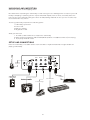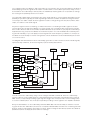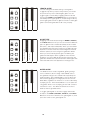
1
SUB PHATT Y
3
IMPORTANT SAFETY INSTRUCTIONS
WARNING - WHEN USING ELECTRIC PRODUCTS, THESE BASIC PRECAUTIONS SHOULD
ALWAYS BE FOLLOWED.
1. Read all the instructions before using the product.
2. Do not use this product near water - for example, near a bathtub, washbowl, kitchen sink, in a wet
basement, or near a swimming pool or the like.
3. This product, in combination with an amplifier and headphones or speakers, may be capable of
producing sound levels that could cause permanent hearing loss. Do not operate for a long period of
time at a high volume level or at a level that is uncomfortable.
4. The product should be located so that its location does not interfere with its proper ventilation.
5. The product should be located away from heat sources such as radiators, heat registers, or other
products that produce heat.
6. The product should be connected to a power supply only of the type described in the operating
instructions or as marked on the product.
7. The power-supply cord of the product should be unplugged from the outlet when left unused for a
long period of time.
8. Care should be taken so that objects do not fall and liquids are not spilled into the enclosure through
openings.
9. The product should be serviced by qualified personnel when:
a. The power supply cord or the plug has been damaged.
b. Objects have fallen, or liquid has been spilled onto the product.
c. The product has been exposed to rain.
d. The product does not appear to operate normally or exhibits a marked change in performance.
e. The product has been dropped or the enclosure damaged.
INSTRUCTIONS PERTAINING TO RISK OF FIRE, ELECTRIC SHOCK, OR INJURY TO PERSONS.
Do not open the chassis. There are no user serviceable parts inside. Refer all servicing to qualified
personnel only.
GROUNDING INSTRUCTIONS: This product must be grounded. If it should malfunction or breakdown,
grounding provides a path of least resistance for electrical current to reduce the risk of electric shock.
This product is equipped with a cord having an equipment grounding connector and a grounding
plug. The plug must be plugged into an appropriate outlet that is properly installed and grounded in
accordance with all local codes and ordinances.
DANGER: Improper connection of the equipment-grounding connector can result in a risk of electric
shock. Check with a qualified electrician or serviceman if you are in doubt as to whether the product
is properly grounded. Do not modify the plug provided with this product – if it will not fit in the outlet,
have a proper outlet installed by a qualified electrician.
TABLE OF CONTENTS
7
7
8
9
UNPACKING & INSPECTION
SETUP & CONNECTIONS
POWER
EXTERNAL AUDIO IN
USB
MIDI
CONTROL VOLTAGE IN
OVERVIEW & FEATURES
9
PRESET PANEL
10
BANK & PATCH BUTTONS
SAVING PRESETS
ACTIVATE PANEL
10
12
13
BASICS OF SOUND
SIGNAL FLOW
OSCILLATORS
15
OVERVIEW
CONTROLS
OCTAVE
WAVE
FREQUENCY
HARD SYNC OSC 2
TRY THIS
PATCH INITIALIZATION
EXPLORE THE OSCILLATORS
OSCILLATOR SYNC
15
MIXER
14
OVERVIEW
CONTROLS
OSC 1
OSC 2
SUB OSC
NOISE
16
FILTER
17
OVERVIEW
CONTROLS
CUTOFF
RESONANCE
MULTIDRIVE
EG AMOUNT
KEYBOARD AMOUNT
17
18
19
ENVELOPES
OVERVIEW
CONTROLS
FILTER ATTACK
FILTER DECAY
FILTER SUSTAIN
FILTER RELEASE
AMPLIFIER ATTACK
AMPLIFIER DECAY
AMPLIFIER SUSTAIN
AMPLIFIER RELEASE
TRY THIS
NOTE ARTICULATION
CLASSIC ELECTRONIC KICK DRUM
20
MODULATION
21
OVERVIEW
CONTROLS
LFO RATE
SOURCE
PITCH AMT
PITCH AMT OSC 2 ONLY
FILTER AMT
WAVE AMT
TRY THIS
LFO WAVEFORMS
PULSE WAVE MODULATION
22
GLOBAL PITCH CONTROLS
MIDI INDICATOR
FINE TUNE
GLIDE RATE
OCTAVE BUTTONS
KEYBOARD
WHEELS
23
SHIFT MODE
26
KNOB AND BUTTON REASSIGNMENTS
ADDITIONAL HIDDEN PARAMETERS
38
MIDI OPERATIONS & CHARTS
42
SERVICE & SUPPORT
43
SPECIFICATIONS
UNPACKING AND INSPECTION
Check the contents of the shipping carton
Be careful when unpacking the Sub Phatty so that nothing is lost or damaged. Do not expose your Sub
Phatty to dripping or splashing and no objects filled with liquids, such as vases, should be placed on
top of it. Moog recommends saving the carton and all packing materials in case you ever need to ship
the instrument for any reason.
The Moog Sub Phatty ships with the following items:
1. Sub Phatty synthesizer
2. Power cord
3. Owner’s manual
4. Registration card
What you will need:
1. A stand or table sufficient to support the Sub Phatty
2. Either a 1/4 inch instrument cable and amplified speakers or headphones with a 1/4” inch plug
3. A properly wired AC outlet
SETUP AND CONNECTIONS
Place the Sub Phatty on a stable surface such as a table or keyboard stand at a height suitable for
playing comfortably.
OUT
EXT IN
PITCH CV
VOL CV
MIDI
IN
External
Audio in
I
O
USB
OUT
AUDIO
FILTER CV
KB GATE
INPUT
USB MIDI
5 Pin DIN MIDI
Control Voltage
7
POWER
Plug one end of the supplied AC cord into the standard IEC power connector on the Sub Phatty’s leftside panel. Plug the other end into an AC outlet. Warning: An apparatus with CLASS I construction
(such as this device) shall be connected to a MAINS socket outlet with a protective earthing connection.
The Sub Phatty’s universal power supply will operate with 50/60Hz AC power sources ranging from
100 to 240 Volts AC using 8-12W. Flip on the power switch located next to the power connector.
NOTE: It may take as long as 60 seconds for the Sub Phatty to warm up before oscillator tuning has
stabilized if you’ve left it outside on a cold night. (Although its oscillators are surprisingly stable, the Sub
Phatty is an analog synthesizer, after all.)
AUDIO OUT
With the MASTER VOLUME turned all the way down, plug one end of a 1/4 inch instrument cable into
the Sub Phatty’s unbalanced AUDIO OUT jack and the other end into an amplified speaker or mixing
console input. Adjust the level by slowly turning the MASTER VOLUME knob clockwise while playing
the keyboard.
If you’ll be using headphones, plug them into the headphones jack (on the front panel’s bottom-right
corner) with HEADPHONE VOLUME turned all the way down. Adjust the level by slowly turning the
HEADPHONE VOLUME knob clockwise while playing the keyboard. Note that MASTER VOLUME must
be turned up as well.
EXTERNAL AUDIO IN
Located just above the AUDIO OUT jack, the jack labeled EXT IN allows the Sub Phatty to shape and
filter external sounds. This is an unbalanced input that accepts a line-level signal. You can adjust the
audio level using Shift mode (see page. 25) or the plug-in editor.
NOTE: You must press a key to pass external audio through the Sub Phatty. You also can use a Moog
FS-1 footswitch, or any 1/4” cable to open the gate. Simply connect to the 1/4” Gate jack.
USB
To use the Sub Phatty with a computer, connect one end of a USB cable to the Sub Phatty’s USB port
and the other end to an available USB port on your computer. The Sub Phatty supports MIDI I/O over
USB, but not audio data.
MIDI
Using the Sub Phatty with an external MIDI device requires one or two MIDI cables. To use the Sub
Phatty as a MIDI controller, connect one end of a MIDI cable to the Sub Phatty’s MIDI OUT jack and the
other end to another device’s MIDI IN jack.
To control the Sub Phatty from an external MIDI controller, connect one end of a MIDI cable to the Sub
Phatty’s MIDI IN jack and the other end to an external controller’s MIDI OUT jack. By default, the Sub
Phatty is set to transmit and receive MIDI data on MIDI Channel 1.
CONTROL VOLTAGE IN
The PITCH CV, FILTER CV, and VOL CV inputs each accepts an expression pedal (such as the Moog EP2) or a control voltage signal from 0 to +5 volts. If you connect an expression pedal to VOL CV, you can
use your foot to control the Sub Phatty’s output level. If you connect an expression pedal to FILTER CV,
you can sweep the filter cutoff in the same manner. The PITCH CV and FILTER CV inputs are calibrated
so that a one-volt change in the control voltage will result in a one-octave change in frequency.
The KB GATE input accepts a +5 volt signal, which causes the Sub Phatty’s envelopes to trigger.
8
OVERVIEW AND FEATURES
The Sub Phatty is a monophonic analog synthesizer, very much in the tradition of other classic Moog
synthesizers. It is housed in a sturdy case containing a 25-note, velocity-sensitive keyboard, with a
front panel that delivers plenty of hands-on controls for designing, saving, and retrieving your own
sounds. Like many instruments, the Sub Phatty is monophonic, meaning that it plays one note at
a time. It offers a 100% analog audio signal path with two exceptionally stable voltage-controlled
oscillators, a square-wave suboscillator, a noise generator, two ADSR envelope generators, and a
voltage-controlled, ladder-type lowpass filter capable of self-oscillation. One feature that makes
the Sub Phatty unique is MultiDrive, a variable multistage drive circuit that delivers overdrive and
distortion. Virtually every function on the Sub Phatty has its own knob, and every knob sends MIDI
Control Change (CC) data.
Although the Sub Phatty’s straightforward signal path and traditional one-knob-per-function user
interface make it ideal for beginning synthesists, it is an excellent addition to any electronic musician’s
studio setup or live performer’s stage rig. Thanks to its MIDI capabilities, you can easily layer the Sub
Phatty with other sound sources or integrate it into a multitrack DAW-based studio. The external audio
input lets you use it to process sounds from other instruments or microphones.
The Sub Phatty’s internal patch memory stores 16 user-rewritable presets. The free editor/librarian/
controller plug-in allows your computer to store as many presets as you like and provides a graphical
user interface for programming your own sounds.
Like other synths in the Voyager and Little Phatty families, the Sub Phatty has syncable audio oscillators
with continuously variable waveforms, as well as a low-frequency oscillator (LFO) that syncs to MIDI
clock and offers a choice of modulation waveforms. In addition to a mono audio output with a dedicated
volume knob, the Sub Phatty has a front-panel headphone output with a separate volume knob.
PRESETS PANEL
BANK AND PATCH BUTTONS
The Sub Phatty ships with 16 presets, and you can replace any of
them with your own patches. (The word patch is a holdover from
modular synthesis, which requires patch cords to connect the
various modules.)
Patches are arranged in four banks, each containing four presets.
On the front panel’s left side, you’ll see two rows of buttons in the
PRESETS section. Use the row on the left to select banks and the
row on the right to select presets within those banks. For example,
to select preset 1 in bank 2, first press the second button on the
left and then press the first button on the right. You can tell at a
glance which preset is active because the corresponding BANK and
PATCH buttons will be illuminated. If you select a new bank, the
new BANK button will pulsate slowly until a new patch is selected.
Take your time, listen to all the presets, and turn some knobs to get
a feel for how you can use them to alter the sounds. Whenever you
want to go back to the original stored preset, just select it again
using the same BANK and PATCH buttons.
NOTE: The PRESETS section’s buttons also provide access to Shift
mode, which allows you to activate “under the hood” features from
the Sub Phatty’s front panel. (To learn more, see page 23.)
9
SAVING PRESETS
Saving presets is a two-finger maneuver. Just remember that whenever you save a preset to a
particular location, the preset previously stored in that location will be deleted.
To save your changes, press and hold the BANK button corresponding to the bank in which you want to
store your new preset. While holding the BANK button, press the PATCH button corresponding to the
location in which you want to store it, hold both buttons for at least one second, and then release them.
NOTE: Both buttons will flash and then go solid again to indicate that your new preset has been stored.
If you release both buttons before one second has elapsed, both buttons will continue flashing. By
pressing and holding the ACTIVATE PANEL button as they’re flashing, you can listen to the preset
currently stored in the selected location to make sure it’s the one you want to replace. Releasing
ACTIVATE PANEL returns to your unsaved patch. At this point, you can either finish saving your preset
by repeating the save procedure or cancel saving by pressing any of the BANK buttons.
ACTIVATE PANEL
Pressing the ACTIVATE PANEL button puts the Sub Phatty in Panel mode. Pressing it again returns the
Sub Phatty to Preset mode. In Panel mode, the front-panel settings determine the sound rather than a
stored preset. The current position of each knob and the status of four buttons determine the sound
coming out of the Sub Phatty. Dialing up sounds in Panel mode is exactly like dialing up sounds in a
classic synth without patch memory, but when you’re finished sculpting your sound, you can save your
work. Saving a preset stores all the settings that define your new sound.
To learn how to create your own patches in Panel mode, continue reading this manual.
BASICS OF SOUND
If you’re new to the world of music synthesis, it helps to have at least a rudimentary understanding of
music and acoustics. Even if you know this stuff like the back of your hand, it never hurts to approach it
from a fresh perspective.
Several qualities distinguish one musical sound from another, including pitch, loudness, duration, and
timbre. Being able to manipulate those qualities allows you to turn raw sound into music.
Simply put, sound occurs when a vibrating object causes the air around it to vibrate. That object could
be a guitar string, a loudspeaker, or anything capable of rapid movement. An individual vibration is
called a wave or cycle, and the rate of vibration is called frequency. Frequency determines the sound’s
pitch, and pitch determines how high or how low you perceive the sound on a musical scale. Frequency
is measured in Hertz (abbreviated Hz), which describes the actual number of times that something
vibrates every second. One thousand cycles per second is called a kilohertz (kHz).
w ave l e n g t h
amplitude
l ow f r e q u e n c y
high frequency
10
BASICS OF SOUND CONT.
Amplitude—the intensity of vibration—determines a sound’s loudness. A high-amplitude sound is
loud, and a low-amplitude sound is soft. A vibrating source’s loudness depends on the amount of air it
displaces, and that depends on how hard it vibrates.
It’s difficult for anyone to identify a musical instrument simply by the pitch or loudness of the sounds
it makes. Every musical sound also has a characteristic tone color or timbre (pronounced tam’–br, as
in tamborine, not tim’–br, as in a tree falling). Differences in timbre make it possible to distinguish one
instrument from another.
If you analyze a single cycle of a musical sound, you can perceive it as a complex combination of
simple sine waves, each wave different in frequency and amplitude. When their frequencies are wholenumber multiples of each other (and in musical sounds, they usually are), those simple waves are called
harmonics. A sound’s timbre depends on its harmonic content. The first harmonic—the one with the
lowest frequency and usually the greatest amplitude—determines its pitch. Higher harmonics are often
called overtones. Normally, the higher the overtone’s frequency, then the weaker its amplitude.
When those harmonics are combined in a musical sound, a single cycle of that sound has a specific
shape, which synthesists call a waveform. Just as the frequencies and relative amplitudes of the
sound’s harmonics determine its waveform, the waveform determines the sound’s timbre.
Instead of producing sounds acoustically the way vibrating objects do, synthesizers generate electrical
signals that are amplified and converted to sound. Just as sound has frequency and amplitude, so
does the kind of alternating current produced by a synthesizer. An analog synthesizer’s primary sound
source is called an oscillator.
The oscillator’s waveform, of course, determines the sound’s harmonic content. Some waveforms
are rich in harmonics, while others have relatively few. Depending on the waveform, some overtones
may be absent altogether. Waveforms with lots of overtones, such as sawtooth and square waves, are
harmonically the most complex. Waveforms with fewer overtones, such as triangle and narrow pulse
waves, are harmonically less complex.
Rather than building up waveforms one harmonic at a time, the way a Hammond organ does, analog
synthesizers like the Sub Phatty provide the means to shape and filter complex, harmonically rich
waveforms to selectively remove, reduce, or emphasize specific harmonics—a technique called
subtractive synthesis.
KB: Keyboard (Pitch Voltage)
VCO: Voltage Controlled Oscillator
VCF: Voltage Controlled Filter
EG: Envelope Generator
LFO: Low Frequency Oscillator
VCA: Voltage Controlled Amplifier
T h e
11
S u b r a c t i v e
S y n t h e s i s
M o d e l
The oscillators, filter, modulators, and other parts are connected in the most useful ways for producing
and modifying electronic signals that result in sounds. Unlike on a modular synthesizer, many connections between the Sub Phatty’s various parts are hardwired, meaning that it is not possible to change
the routing of the pathways that connect them.
The electrical signals within a synthesizer are either audio signals or control signals, depending on the
pathway they follow. Typically, an audio signal begins with an oscillator and passes through the filter
on its way to the audio output. Control signals are used to change things, like the pitch, timbre, waveshape, or loudness of an audio signal.
Any time a signal controls something, no matter whether it’s controlling an audio signal or another
control signal, we say that it modulates it. In synth-speak, you could say that a steering wheel modulates a car’s direction and the accelerator pedal modulates its speed. When you play the Sub Phatty’s
keyboard, the key you press modulates the instrument’s pitch. You can modulate filter cutoff by turning a knob manually, or you can apply a control signal from a low-frequency oscillator or envelope to
modulate it electronically. It’s worth noting that a control destination can be modulated by more than
one control source.
The diagram below illustrates how the Sub Phatty generates sound. It shows the flow of audio signals,
represented by solid lines, and control signals, represented by dotted lines.
VCO 1
SUB LVL
FILT POLE
SELECT
VCO 1
LVL
MULTIDRIVE
VCO 1 MOD
& CNTRL
PITCH 1 CV
& MOD
NOTE
SYNC
PITCH 2 CV
& MOD
OSC 1-2
SYNC
VCO 1
SUB
SUB 1
VCO 1
WAVE
VCO 1
VCO 1
CORE
H. PHONE
AUDIO
MIXER
VCO 2
CORE
VCO 2
WAVE
VCO 2
NOISE
CORE
NOISE
LADDER
FILTER
MULTIDRIVE
VCA
AUDIO
OUT
VCO 2 MOD
& CNTRL
VCO 2
LVL
NOISE
LVL
EXT AUDIO
LVL
EXT. AUDIO
EXT
AUD
FILTER EG
CV & MOD
RESONANCE
VCA EG
& CV
You can control the Sub Phatty using control voltages and MIDI commands. When the Sub Phatty
receives either a control signal from the onboard keyboard or a Note On command from an external
MIDI source, it responds by sending a gate signal to trigger the envelopes and a control voltage (CV)
to control oscillator pitch. The envelopes respond by sending control signals to the amplifier and filter.
Every knob and button on the Sub Phatty transmits MIDI data. This functionality is useful for recording your knob turns and button presses into a computer-based DAW, as well as for controlling external
devices using the Sub Phatty’s front-panel controls. All the settings that make up a patch are called its
parameters, which is simply another name for settings.
12
OSCILLATORS
OVERVIEW
Oscillator 1 and oscillator 2 are the Sub Phatty’s primary
sound sources. They generate four basic waveforms:
triangle, sawtooth, square, and pulse.
The triangle wave consists of odd-numbered harmonics
only. Its fundamental is very strong, and its overtones are
very weak, making it less harmonically complex than other
waveforms. By mixing a triangle from one oscillator with
a more complex wave from the other, you can emphasize
one particular harmonic without mucking things up with
unwanted overtones.
An unfiltered sawtooth wave is much brighter, because
it contains all the natural harmonics. As the harmonics
ascend in frequency, they grow weaker in amplitude.
Sawtooth waves are useful for synthesizing bass,
simulating brass instruments, and more.
Although a pulse wave contains only odd-numbered
harmonics, it offers the most flexibility because you can
change the balance of those odd-numbered harmonics by
changing its shape. Think of a pulse-wave oscillator as a
switch you can turn off and on hundreds or thousands of
times per second. In a single pulse wave, the “switch” is
either on or off. Its pulse width is the proportion of the wave that’s on, usually expressed as a
percentage. A square wave is simply a pulse wave with 50% pulse width, meaning that in a single cycle,
it is on half the time and off half the time. If its frequency is 440Hz, that means it goes on and off 440
times every second, and the result you hear is the pitch A above middle C. Every pulse width has its
own characteristic sound, because each has a unique harmonic structure, making a variety of basic
timbres possible.
Unlike most synths, which simply switch between basic waveforms, the Sub Phatty allows you
to gradually change the oscillator’s output from one waveform to another, so it can generate
something partway between a sawtooth and a square wave, for example. We refer to such controls as
continuously variable because there are no discrete steps between settings.
In normal operation, either the keyboard or external MIDI data controls oscillator pitch. You can also
apply the LFO or the filter envelope to modulate oscillator pitch and waveform.
OSCILLATOR CONTROLS
OCTAVE: Use this knob to control either oscillator’s pitch range. Pitch range is expressed in feet, a
throwback to the age of pipe organs, when a pipe’s physical length determined its pitch. The Sub
Phatty’s OCTAVE knobs cover four pitch ranges corresponding to four octaves. The lowest setting is
16’, and the highest setting is 2’.
WAVE: Use this knob to vary either oscillator’s waveform from triangle to sawtooth to square to narrow
pulse wave. Turning the knob clockwise from the triangle to sawtooth position increases the oscillator’s
harmonic content. Continuing to turn it to the square-wave position weakens and then eliminates evennumbered harmonics while strengthening odd-numbered harmonics. Turning it from the square to
narrow-pulse position changes its harmonic content further by weakening the overtones relative to the
fundamental frequency.
13
OSCILLATOR CONTROLS CONT.
FREQUENCY: This knob is used to fine-tune oscillator 2’s pitch within its selected range. The knob’s
range is seven semitones higher or lower than its center position. At its center position, oscillator 2 is
tuned to oscillator 1. Turning it just slightly out of tune with oscillator 1 can yield interesting detuned
or phasing effects.
HARD SYNC OSC 2: This button locks oscillator 2’s phase to oscillator 1, eliminating any phase
differences between them. The HARD SYNC OSC 2 button illuminates when it’s engaged.
When both oscillators are in sync, every time that oscillator 1 begins a new cycle, it forces oscillator
2 to begin its cycle at the same instant, regardless of whether its previous cycle is complete. As a
result, hard sync forces oscillator 2’s waveform to take on a different shape—typically one with greater
harmonic complexity. Because oscillator 2 is in sync with oscillator 1, their combined harmonic content
depends on their pitch relationship, so that changing oscillator 2’s frequency will have an immediate
effect on timbre. For that reason, modulating oscillator 2’s frequency opens up some outstanding
waveshaping opportunities when HARD SYNC OSC 2 is engaged.
NOTE: If oscillator 1’s frequency is higher than oscillator 2’s, oscillator 2 will be unable to complete its
cycle, resulting in little or no output from oscillator 2.
TRY THIS
PATCH INITIALIZATION
1. Press the ACTIVATE PANEL button.
2. In the FILTER section, turn the CUTOFF knob all the way up, the EG AMOUNT knob to
center position, and the remaining knobs all the way down.
3. In the ENVELOPES section, turn the SUSTAIN knobs all the way up and the remaining
knobs all the way down.
4. Set the OCTAVE knobs for both oscillators to 16’ and center the OSCILLATOR section’s
remaining knobs. The HARD SYNC OSC 2 and PITCH AMT OSC 2 ONLY buttons should be
turned off.
5. In the MODULATION section, turn the LFO RATE to 8 and the remaining knobs all the way
down. Make sure the MOD wheel is turned all the way down, too.
6. Next to the PRESETS section, FINE TUNE and OCTAVE should be centered and GLIDE
RATE should be all the way down.
7. Finally, turn all the MIXER knobs fully counterclockwise.
When you play the keyboard with these settings, you shouldn’t hear anything. This procedure
initializes the front panel and gives you a starting place for creating your own patches and
exploring the Sub Phatty’s capabilities.
EXPLORE THE OSCILLATORS
After patch initialization, turn up the OSC 1 knob in the MIXER section. Listen carefully as you play
the keys while slowly turning oscillator 1’s WAVE knob to the triangle, sawtooth, square, and pulse
positions. Listen to what happens when you turn the WAVE knob quickly while playing.
Now turn up oscillator 2 in the mixer. While holding a key, turn oscillator 2’s FREQUENCY
knob to adjust its tuning relative to oscillator 1. Notice the varied effects of adjusting them
slightly out of tune, ranging from obvious beating between the pitches to mild phasing
between the slightly detuned oscillators.
If you turn the FREQUENCY knob all the way up, you’ll hear oscillator 2 tuned seven
semitones (an interval of a perfect 5th) higher than oscillator 1. If you turn it all the way down,
it will be seven semitones lower than oscillator 1. (For extra credit, try to tune them a major 3rd
and a perfect 4th apart, too.) Now tune the oscillators as close to unison as you can by turning
the knob to its center position again.
14
TRY THIS
OSCILLATOR SYNC
With the HARD SYNC OSC 2 button engaged, you can step through the harmonic series by
turning oscillator 2’s FREQUENCY knob. To begin, make sure both oscillators are turned up
in the mixer. Turn both OCTAVE knobs to their lowest settings, and then press the HARD
SYNC OSC 2 button so that it’s illuminated. Begin with the FREQUENCY knob turned fully
counterclockwise and slowly turn it while listening for how the overtones change. Using your
ears, try to step through each harmonic one at a time. Now turn oscillator 2’s OCTAVE knob
to its 8’, 4’, and 2’ settings and slowly turn the FREQUENCY knob again to hear the harmonic
series in successively higher octaves.
MIXER
OVERVIEW
The mixer lets you combine audio signals from each of the Sub
Phatty’s four internal inputs. Each has a dedicated knob for controlling
its relative level. In addition to level knobs for each oscillator, the
mixer has level knobs for the sub oscillator and noise generator. When
a level knob is turned fully counterclockwise, its input is effectively
turned off. Turning it clockwise from 0 increases the level until it
reaches its maximum at 12. Settings higher than 6 overdrive the filter,
meaning that you can specify which sources are distorted and which
simply pass through the filter.
MIXER CONTROLS
OSC 1: Use this knob to control oscillator 1’s level. Settings higher than
6 push the level beyond unity, imparting gentle filter distortion. A
setting of 6 or below delivers a clean signal to the filter.
OSC 2: Use this knob to control oscillator 2’s level. Settings higher
than 6 push the level beyond unity, imparting gentle filter distortion.
A setting of 6 or below delivers a clean signal to the filter.
SUB OSC: Use this knob to control the sub oscillator’s level. Settings
higher than 6 push the level beyond unity, imparting gentle filter
distortion. A setting of 6 or below delivers a clean signal to the filter.
The Sub Phatty’s sub oscillator is always tuned exactly one octave below oscillator 1’s pitch, and its
waveform is always a square wave. Typically, the sub oscillator adds a solid foundation to the Sub
Phatty’s sound. It is especially useful for crafting monstrous Moog bass patches.
NOISE: Use this knob to control the Sub Phatty’s noise generator level. Settings higher than 6 push the
level beyond unity, imparting gentle filter distortion. Noise is useful for programming punchy percussion and other unpitched sounds.
Whereas an oscillator generates a pitched waveform, noise is an unpitched sound source. Just as white
light contains all colors of the visual spectrum in equal proportion, white noise contains a random
distribution of all audible frequencies. Every frequency has equal amplitude. We hear white noise as
a constant ssshh sound, like an FM radio between stations. Because of the way our brains respond to
white noise, the higher frequencies sound more prominent than the lower ones.
The Sub Phatty’s noise generator produces a signal called pink noise. Pink noise has equal amplitude in
every octave, making it sound deeper than white noise—more like the sound of a waterfall. Most synthesists consider pink noise more useful than white noise.
15
FILTER
OVERVIEW
The number and relative strengths of a sound’s harmonic
frequencies determine its tone color or timbre. The Sub
Phatty contains a filter for removing certain frequencies
from audio signals. Because filtering gives you control
over an audio signal’s harmonic content, it physically
alters the waveform being filtered.
The Sub Phatty has a classic Moog lowpass ladder filter
with four selectable slopes (see Hidden Parameters on
pg.26). Lowpass filters pass all frequencies up to a point
called the cutoff frequency and gradually roll off, or
attenuate, frequencies above that point. You can change
the cutoff manually using a knob, or you can change it
by applying a signal from a control source such as an
envelope or LFO.
Turning the cutoff all the way down closes the filter so
that nothing passes through it. Raising the cutoff opens
the filter. As you turn the CUTOFF knob clockwise from
its lowest position, first you’ll hear only the audio signal’s
lowest frequencies, and then the timbre will grow gradually
brighter. The filter envelope, in combination with the
CUTOFF knob’s setting, is the filter’s primary control source.
Another characteristic of the Sub Phatty’s filter is resonance. Resonance increases the level of audio
frequencies closest to the cutoff frequency by making the filter roll off frequencies less gradually. It
regenerates those frequencies by feeding them back to the filter. Turning up the resonance emphasizes
harmonics closest to the cutoff frequency and exaggerates any changes to the cutoff frequency.
FILTER CONTROLS
CUTOFF: Use this knob to change the filter’s cutoff frequency. Its lowest setting is 20Hz, which
effectively closes the filter and doesn’t allow any audio to pass through. Its highest setting is 20kHz,
which opens the filter completely and allows all audio to pass through.
RESONANCE: Use this knob to control how much signal is routed from the filter’s output back to
its input. Turning it clockwise increases the resonance, causing a peak in amplitude at the cutoff
frequency. Settings above 7 cause the filter to self-oscillate.
MULTIDRIVE: MultiDrive is the Sub Phatty’s distortion processor, offering effects ranging from
asymmetrical, tube-like warmth to aggressive hard clipping, with a smooth continuous transition in
between. The MULTIDRIVE knob controls how hard you drive the OTA and FET stages, which are located
between the filter and the amplifier in the signal path. The higher the setting, then the more aggressive
the clipping effect. Varying amounts of MultiDrive can give your sounds a distinct tonal edge, as well as
make them more responsive to changes in filter resonance, waveform, and oscillator level.
EG AMOUNT: Use this knob to control how much the filter envelope modulates the filter’s cutoff
frequency. In other words, EG AMOUNT controls the depth of the envelope generator’s effect on the filter.
Notice that the EG AMOUNT knob is bipolar, meaning that its control value is positive when it’s turned
up and negative when it’s turned down. Turning it clockwise from center causes the envelope to raise
the cutoff frequency from the CUTOFF knob’s setting. Turning it counterclockwise from center causes
the envelope to lower the cutoff frequency from the CUTOFF knob’s setting.
16
FILTER CONTROLS CONT.
The depth of the envelope’s effect on the cutoff frequency also depends a lot on the CUTOFF setting.
If the setting is very high and you adjust the EG AMOUNT to raise it further, then the envelope will have
little effect. The lower the cutoff frequency, then the more the envelope will be able to modulate it. On
the other hand, if the setting is very low and you adjust the EG AMOUNT to lower it further by turning
the knob counterclockwise, again, the envelope will have little effect.
KB AMOUNT: Use this knob to specify how much the filter cutoff tracks the keyboard; that is, how
much the keyboard pitch affects the filter’s lowpass frequency. With KB AMOUNT turned up halfway,
the filter cutoff will follow the keyboard pitch at a 1:1 ratio centered around middle C (MIDI note 60).
KB AMOUNT at maximum sets a 2:1 ratio for filter keyboard tracking.
ENVELOPES
OVERVIEW
When you make any sound, it may take
a moment for that sound to reach its
maximum amplitude and brightness.
This initial moment is called the sound’s
attack. An attack may be gradual (like
a cymbal roll), abrupt (like a cymbal
crash), or anything in between. The
attack often tells us more about how
an instrument is played than any other
characteristic. Likewise, when the
sound ends, it may take a moment to
die away completely, or it may stop
suddenly. This final drop in amplitude
and brightness is called its release. The
attack and release, along with variations
in amplitude and timbre that occur
between the attack and release, make
up the sound’s envelope.
The Sub Phatty shapes electronic sounds using two envelope generators (abbreviated EG). One
envelope affects the Sub Phatty’s filter, which controls timbre, and the other affects its amplifier, which
controls amplitude. When you press a key on the keyboard, it sends a signal that tells the envelope
generator to begin the attack. In voltage-controlled synthesizers like the Sub Phatty, this signal is called a
gate. The gate ends when you release the key, telling the envelope generator to begin the release.
Each of the Sub Phatty’s envelope generators has four stages: attack, decay, sustain, and release
(abbreviated ADSR). Just as attack is the time it takes a level to peak, the decay is the time it takes
to fall to a steady level, called the sustain. The sustain level is held until the note ends. At that point,
the signal returns to zero at a rate determined by the release setting. Whereas the attack, decay, and
release stages are specified as lengths of time, sustain is a control-signal level.
17
ADSR
amplitude
release
sustain
d e c ay
attack
time
When you play the Sub Phatty, your keyboard technique determines how the envelope generators
respond, which impacts your musical expression and articulation. If you release the key before the
envelope reaches either its maximum or sustain level, the release stage immediately takes effect. When
you play staccato (very short notes), the envelope may never reach its decay stage, depending on its
attack setting. Playing legato—holding down each key for the note’s full duration without lifting your
fingers between notes—prevents the envelope from retriggering its attack stage on subsequent notes.
In that case, the envelope maintains its sustain level until you trigger the release stage by lifting your finger.
ENVELOPE CONTROLS
FILTER ATTACK: Use this knob to specify the time it takes the filter frequency to ascend from the
CUTOFF knob’s manual setting to its maximum level, which is determined by the filter’s EG AMOUNT
setting. Its value ranges from 1 millisecond to 10 seconds.
When you use the filter envelope to modulate pitch or wave amount, the ATTACK knob specifies the
time it takes the control level to ascend to its maximum value.
FILTER DECAY: Use this knob to specify the time it takes the filter frequency to descend from its
maximum level to its sustain level. Its value ranges from 1 millisecond to 10 seconds.
When you use the filter envelope to modulate pitch or wave amount, the DECAY knob specifies the
time it takes the control level to descend from its maximum value to its sustain level.
FILTER SUSTAIN: Use this knob to specify the filter cutoff frequency once the decay stage is complete.
The sustain stage is held until the envelope receives a Note Off command or the gate ends. Its value
ranges from zero to 100 percent, calibrated 1 to 10. Note that the filter’s EG AMOUNT determines the
depth of its effect.
When you use the filter envelope to modulate pitch or wave amount, the SUSTAIN knob specifies the
control value that is held once the decay stage is complete.
18
ENVELOPE CONTROLS CONT.
FILTER RELEASE: Use this knob to specify the time it takes the filter cutoff to descend from its sustain
value to the CUTOFF knob’s manual setting. Its value ranges from 1 millisecond to 10 seconds.
When you use the filter envelope to modulate pitch or wave amount, the RELEASE knob specifies the
time it takes the control level to descend from the sustain value to zero.
AMPLIFIER ATTACK: Use this knob to specify the time it takes the mixer output’s amplitude to ascend
from zero to its maximum value. Its value ranges from 1 millisecond to 10 seconds.
AMPLIFIER DECAY: Use this knob to specify the time it takes the mixer output’s amplitude to descend
from its maximum level to its sustain level. Its value ranges from 1 millisecond to 10 seconds.
AMPLIFIER SUSTAIN: Use this knob to specify the mixer output’s amplitude once the decay stage is
complete. The sustain stage is held until the envelope receives a Note Off command or the gate ends.
Its value ranges from zero to 100 percent, calibrated 1 to 10.
AMPLIFIER RELEASE: Use this knob to specify the time it takes the mixer output’s amplitude to
descend from its sustain value to zero. Its value ranges from 1 millisecond to 10 seconds.
TRY THIS
NOTE ARTICULATION
Load your favorite melodic preset. For both envelopes, turn the attack to just under one
second and the release to just over one second. Play the keys staccato, making sure to lift
your fingers between each note. Notice that you can hear the release stage after every note,
especially when you pause long enough for the envelope to return to zero. Now play legato,
making sure you don’t lift you fingers between notes. Hear the difference? After the first
note, the envelopes bypass their attack, decay, and release stages when you play legato and
maintain their sustain levels until you lift your fingers. Playing with a combination of staccato
and legato articulations adds to the expressivity of your performance.
CLASSIC ELECTRONIC KICK DRUM
One of the simplest sounds you can synthesize is a kick drum, also called a bass drum.
Perhaps the best example of an electronic kick drum comes from a classic analog drum
machine, the 808. It uses a sine wave and a 2-stage envelope generator to create the sound.
The Sub Phatty lets you re-create this vintage sound with just a bit more thump.
Although synthesizing most percussion begins with the noise generator, the kick drum is an
exception. After initializing the patch, turn up the mixer level on oscillator 1. Turn oscillator
1’s OCTAVE knob to 16’ and the WAVE knob to triangle. On the amplifier envelope, turn
the ATTACK and SUSTAIN knobs all the way down. Now adjust the DECAY and RELEASE
knobs to exactly 1 second. Because triangle waves have a few weak overtones, you’ll need to
filter those out to approximate a sine wave. Turn the filter CUTOFF knob to 320Hz and the
MULTIDRIVE knob to 9 O’clock. On the front panel’s left side, press the left OCTAVE button
to lower the pitch an octave, and strike the low C key. If necessary, slightly adjust the CUTOFF
and DECAY to taste. And there you have it: a sound that’s propelled millions of people out on
the dance floor.
19
MODULATION
OVERVIEW
Controlling modulation (abbreviated as mod) is an important
aspect of programming and playing synthesizers. When you
modulate a synth’s audio signal, you’re changing something
about the way it sounds. When you modulate a control signal,
you’re changing something about its effect on whatever
it’s controlling. Synthesizers route their control signals from
modulation sources to modulation destinations. On the Sub
Phatty, a changing control signal can modulate pitch, filter
cutoff, and waveform shape. You control the modulation
signal’s depth using the MOD wheel immediately to the left of
the keyboard.
All LFOs generate repeating waveforms in the sub-audio
range. The Sub Phatty’s LFO has an extended range capable
of generating audio frequencies as well. At sub-audio rates,
the LFO is useful for generating repeating effects. At audio
rates, the LFO adds harmonic complexity to its destination.
When an LFO modulates oscillator frequency, the oscillator’s
pitch follows the shape of the modulating waveform. If the
LFO’s output is a triangle wave, the pitch rises and falls at
a regular rate. At the proper rate and depth, this type of
modulation is called vibrato. Many performers rely on
vibrato to add expression to their performances. A violinist or guitarist employs vibrato with a
shaking motion of the hand as it applies pressure to the string. A singer subtly fluctuates vocal pitch.
A synthesist uses an LFO to modulate oscillator frequency. The LFO RATE knob controls the rate of
modulation, and the mod wheel controls its depth.
MODULATION CONTROLS
LFO RATE: By default, this knob varies the low-frequency oscillator’s modulation rate from 0.1Hz (one
cycle every 10 seconds) to 100Hz (100 cycles per second). You can change this range in Shift mode
(see Hidden Parameters on pg. 28).
SOURCE: Use this knob to specify whether the mod source is the LFO or the filter envelope, as well
as the LFO waveform. At its counterclockwise position, the LFO generates a triangle wave, which is
particularly useful for vibrato. Turning the knob clockwise, the next position generates a square wave,
which is useful for performing trills and tremolo effects. The next two positions generate sawtooth and
ramp (reverse sawtooth) waves. Applied to pitch, sawtooth-wave modulation is useful for simulating
alarms, ray guns, and other ascending and descending effects.
The fifth position uses sample-and-hold as a mod source. Without going into a lot of technical
explanation, think of sample-and-hold as a source of random control signals.
The SOURCE knob’s most clockwise position, labeled FILTER EG, bypasses the LFO and routes the
filter’s envelope to the modulation destinations, which are determined by the settings of the PITCH
AMT, FILTER AMT, and WAVE AMT knobs below.
PITCH AMT: Use this knob to specify the depth of pitch variation applied to the oscillators when the
MOD wheel is engaged. If the mod source is the filter envelope, you can control changes in pitch using
the envelope’s attack, decay, sustain, and release settings.
20
MODULATION CONTROLS CONT.
PITCH AMT OSC 2 ONLY: Pressing this button applies pitch modulation to oscillator 2 only, with no
effect on oscillator 1. The button illuminates when it’s engaged.
If you engage the HARD SYNC OSC 2 button (which phase-locks the oscillators), then modulating
oscillator 2’s frequency with an LFO or envelope will change the oscillator’s harmonic content but not
its pitch.
FILTER AMT: Use this knob to specify the depth of variation applied to the filter’s cutoff frequency
when the MOD wheel is engaged. Applying LFO modulation to the filter is useful for generating slow
filter sweeps, wobbles, and repeating effects.
WAVE AMT: Use this knob to specify the depth of variation applied to the waveform of both
audio oscillators when the MOD wheel is engaged. As the waveform is modulated, the amplitudes,
frequencies, and phase of the harmonics change dynamically. Waveform modulation has no effect on
the sub oscillator, which always generates a square wave.
NOTE: Using Shift mode or the plug-in editor, you can also assign Wave Amount to affect oscillator 1 or 2
independently (see Hidden Parameters on pg. 28).
TRY THIS
LFO WAVEFORMS
It’s likely that much of the time when you’re playing melodic sounds, you’ll use the MOD wheel
to control note vibrato to make your playing more expressive. To try this, begin by selecting
your favorite lead or solo preset. In the MODULATION section, turn the SOURCE knob
counterclockwise to its triangle-wave position. Turn PITCH AMT up to 2 and turn LFO RATE
to 6. Play a note and nudge the MOD wheel up slightly to produce vibrato. Play a few more
notes, adding vibrato during sustained notes when it feels appropriate. Adjust the LFO RATE
to taste.
Learn your way around the LFO by trying the other waveforms and destinations, and by
varying the LFO RATE and depth. Begin by turning up the PITCH AMT knob slightly, raising
the MOD wheel, and then switching the SOURCE knob to the square wave setting. Square
wave LFO modulation produces a trill that alternates between two pitches. Varying the LFO
RATE changes the speed of the trill, and varying the PITCH AMT or the MOD wheel depth
changes its interval.
Now vary the LFO RATE, PITCH AMT, and MOD wheel depth using the SOURCE knob’s
sawtooth, ramp, and sample-and-hold settings. Notice that sawtooth and ramp-wave
modulation work best at slow rates, and sample-and-hold modulation works really well when
it’s applied to modulate the filter with RESONANCE turned up at least halfway. When you’re
exploring filter modulation, try turning down the oscillator signal and turning up the noise.
PULSE WAVE MODULATION
By routing LFO or envelope modulation to an oscillator’s wave amount, you give the
waveform motion by changing its harmonic content dynamically. As the control signal
changes, so does the waveform. Although the Sub Phatty’s continuously variable oscillators
let you apply modulation to any waveform, it’s most traditional to modulate a pulse wave.
Beginning with an initialized patch, turn up oscillator 1 in the MIXER section and turn the
WAVE knob halfway between square and pulse. Set the LFO RATE at approximately 3Hz and
the LFO waveform to triangle.
21
PULSE WAVE MODULATION CONT.
When you press a key and push up the MOD wheel, you’ll hear the LFO’s effect on pulse
width. Push it up only slightly, and you’ll hear a dramatic sweeping of the harmonics that
sounds a bit like a chorusing effect. Turn it up more, and you’ll hear the entire waveform being
canceled in rhythm with the LFO. That’s because you’re pushing the pulse wave beyond its
maximum width, so that the waveform doesn’t have a chance to cycle back to its starting
point. Applying LFO modulation to pulse width is most useful at rates normally used for
vibrato—usually between 6 and 9Hz.
In the MODULATION section, turn the SOURCE knob to the FILTER EG position and push the
MOD wheel up all the way. If you play the keyboard and the filter envelope is at its initialized
setting, you won’t hear anything until you release the keys. Again, that’s because the pulse
width is pushed beyond its maximum. Lower the MOD wheel to about halfway and play
around with the filter envelope settings to get a feel for the envelope’s effect on pulse width.
GLOBAL PITCH CONTROLS
MIDI INDICATOR: This LED illuminates whenever the Sub Phatty receives MIDI
data through either its MIDI IN or USB PORT.
FINE TUNE: Use this knob to adjust the frequency of both oscillators as much
as one semitone up or down from its center position. Fine-tuning is useful for
putting the Sub Phatty in tune with any other instruments that deviate slightly
from standard pitch.
GLIDE RATE: Glide, also called portamento or glissando, causes smooth pitch
changes between notes. Use this knob to specify how much time it takes to
transition from one pitch to the next when you play the keyboard. Although
glide is normally applied to every note you play when it’s engaged, you can
turn on legato glide using Shift mode (see Hidden Parameters on pg.26).
OCTAVE BUTTONS: Use these buttons to extend the Sub Phatty’s keyboard
beyond its normal two-octave range. Pressing the left button once transposes
the Sub Phatty’s pitch down an octave, and pressing it again transposes it
down another octave. Likewise, pressing the right button transposes the
pitch up an octave, and pressing it again transposes it up another octave. The
illuminated LED indicates the current transposition. The buttons also transpose
the MIDI Note Numbers that the Sub Phatty transmits by corresponding amounts.
Over time, you’ll discover that you can overcome the limitations of a 25-note keyboard once you
become proficient at pressing the OCTAVE buttons at the right moment. In fact, using the OCTAVE
buttons gives the Sub Phatty’s keyboard a seven-octave range.
KEYBOARD: The Sub Phatty’s 25-note keyboard is velocity-sensitive, so that it transmits MIDI Velocity
data in response to how fast you press the keys.
WHEELS: The PITCH and MOD wheels located to the left of the keyboard can contribute greatly to
the expressivity of your playing. Use the PITCH wheel to smoothly bend pitch during performance.
By default, it transposes pitch up two semitones and down two semitones. However, you can change
either interval in Shift mode (see Hidden Parameters on pg. 26). The PITCH wheel is spring-loaded to
automatically return to the center position.
The MOD wheel controls the depth of modulation. At its minimum setting, modulation is turned off. At
its maximum setting, modulation is at full throttle. The depth of the MOD wheel’s effect depends on
the settings of the PITCH AMT, FILTER AMT, and WAVE AMT knobs.
22
SHIFT MODE
Although you can control all of the Sub Phatty’s functions directly
from the front panel, you’ll need to dig a little deeper to reach some
of them. Shift mode reassigns several front-panel controls so you can
use them to edit hidden parameters. Like all parameters, changes you
make in Shift mode are memorized when you save your preset.
Engage Shift mode by holding down the BANK 4 button and then
pressing the ACTIVATE PANEL button. When you do, all the BANK
and PATCH buttons will go dark and the ACTIVATE PANEL button will
blink. Pressing ACTIVATE PANEL again will cancel Shift mode and
return all the controls to their normal functions.
KNOB & BUTTON REASSIGNMENTS IN SHIFT MODE
PARAMETER: FILTER ENVELOPE DELAY
KNOB: FILTER ENVELOPE ATTACK
Adding a delay stage to the filter envelope lets you specify a timed pause
before the onset of the attack, effectively turning an ADSR envelope into a
DADSR envelope. By engaging Shift mode and turning the amplifier envelope’s
ATTACK knob, you can vary the envelope’s delay time from a minimum of 0 to
a maximum of 10 seconds.
PARAMETER: FILTER ENVELOPE HOLD
KNOB: FILTER ENVELOPE DECAY
Adding a hold stage to the filter envelope lets you specify a fixed delay
between the attack and sustain stages, effectively turning an ADSR envelope
into an AHDSR envelope. During this stage, the filter’s cutoff frequency is held
at its maximum level, which is determined by the filter’s EG AMOUNT setting.
By engaging Shift mode and turning the filter envelope’s DECAY knob, you can
vary the envelope’s hold time from a minimum of 0 to a maximum of 10 seconds.
PARAMETER: VELOCITY TO FILTER ENVELOPE AMOUNT
KNOB: FILTER ENVELOPE SUSTAIN
To make your sounds get brighter as you press the keys faster on the keyboard,
engage Shift mode and turn up the filter envelope’s SUSTAIN knob. The knob’s
range varies from 0 to 100%.
23
KNOB & BUTTON REASSIGNMENTS CONT.
PARAMETER: VELOCITY TO FILTER ENVELOPE DECAY/RELEASE
KNOB: FILTER ENVELOPE RELEASE
Changing this setting lets you specify how much velocity affects the filter
envelope’s decay and release times. To lengthen the decay and release in
response to how hard you play on the keyboard, engage Shift mode and turn
up the filter envelope’s RELEASE knob. The knob’s range is from 0 to 100%.
PARAMETER: AMPLIFIER ENVELOPE DELAY
KNOB: AMPLIFIER ENVELOPE ATTACK
Adding a delay stage to the amplifier envelope lets you specify a timed pause
before the onset of the attack, effectively turning an ADSR envelope into a
DADSR envelope. By engaging Shift mode and turning the amplifier envelope’s
ATTACK knob, you can vary the envelope’s delay time from a minimum of 0 to a
maximum of 10 seconds. The Amplifier Envelope Delay stage only occurs when
the envelope generator is in Looping mode (see Hidden Functions on pg.26).
PARAMETER: AMPLIFIER ENVELOPE HOLD
KNOB: AMPLIFIER ENVELOPE DECAY
Adding a hold stage to the amplifier envelope lets you specify a fixed delay
between the attack and sustain stages, effectively turning an ADSR envelope
into an AHDSR envelope. During this stage, the mixer output’s amplitude is
held at its maximum value. By engaging Shift mode and turning the amplifier
envelope’s DECAY knob, you can vary the envelope’s hold time from a minimum
of 0 to a maximum of 10 seconds.
PARAMETER: VELOCITY TO AMPLIFIER ENVELOPE AMOUNT
KNOB: AMPLIFIER ENVELOPE SUSTAIN
Your patches will be much more dynamic if you make a habit of programming
their velocity sensitivity. To make your sounds get louder as you press the keys
faster on the keyboard, engage Shift mode and turn up the amplifier envelope’s
SUSTAIN knob. The knob’s range varies from 0 to 100%.
PARAMETER: VELOCITY TO AMPLIFIER ENVELOPE DECAY/RELEASE
KNOB: AMPLIFIER ENVELOPE RELEASE
Changing this setting lets you specify how much velocity affects the amplifier
envelope’s decay and release times. To lengthen the decay and release in
response to how fast you press the keys on the keyboard, engage Shift mode
and turn up the amplifier envelope’s RELEASE knob. The knob’s range is from 0
to 100%.
24
KNOB & BUTTON REASSIGNMENTS CONT.
PARAMETER: EXTERNAL INPUT LEVEL
KNOB: NOISE
To manually control the level of signals coming from the Sub Phatty’s EXT IN
jack, engage Shift mode and turn the NOISE knob.
PARAMETER: OSCILLATOR 2 BEAT FREQUENCY
KNOB: OSCILLATOR 2 FREQUENCY
Engage Shift mode and turn oscillator 2’s FREQUENCY knob to set the “beat
frequency” of oscillator 2 against oscillator 1. The range is plus or minus 3.5 Hz,
with no detuning (0Hz) in the middle. This parameter creates a linear constant
detuning of oscillator 2 relative to oscillator 1, so that oscillator 2 is always
detuned by the same number of cycles per second (Hz) regardless of the
musical pitch. The result is a musical detuning effect which phases or “beats”
at a consistent rate on every note.
By contrast, the OSCILLATOR 2 FREQUENCY knob detunes oscillator 2 by
musical cents, where the rate of beating between oscillators is halved or
doubled as you play an octave lower or higher in pitch. NOTE: for this reason,
if you want a constant beat frequency at all pitches, make sure that the regular
OSCILLATOR 2 FREQUENCY control is centered. If you want absolute unison
between oscillator 2 and oscillator 1, make sure this BEAT FREQUENCY control
is centered.
PARAMETER: OSCILLATOR GATE RESET
BUTTON: HARD SYNC OSC 2
Engage Shift mode and press the HARD SYNC OSC 2 button to turn on
oscillator reset. This function forces the audio oscillators to simultaneously
begin their cycles whenever you play a new note. When turned on, the result is
a more well defined leading edge to sounds with a hard attack.
PARAMETER: LFO GATE RESET
BUTTON: PITCH AMT OSC 2 ONLY
Engage Shift mode and press the PITCH AMT OSC 2 ONLY button to turn on
the LFO gate reset. This function forces the LFO to begin a new cycle each time
you play a new note.
When LFO reset is turned off, the LFO runs freely, without regard to the notes
you’re playing. When it’s turned on, however, its instantaneous amplitude
always ascends from its zero-crossing point whenever an envelope is triggered.
This can be especially important for creating realistic vibrato when you’re
emulating acoustic instruments, or for programming filter sweeps.
25
ADDITIONAL HIDDEN PARAMETERS IN SHIFT MODE
You can access the Sub Phatty’s additional hidden parameters using a combination of buttons and the
keyboard. First engage Shift mode by holding down the BANK 4 button and pressing the ACTIVATE
PANEL button. Then enter a code from the hidden parameter chart using the BANK and PATCH
buttons to select the parameter. Finally, press a key on the keyboard to select the parameter’s value.
All parameters have at least two possible values (ON and OFF), and some parameters have 24
possible values. Lower keys specify lower values, and higher keys specify higher values. Because
most parameters have a limited range of values, they respond to only the leftmost keys. The low C key
always selects the lowest value. For parameters with two values, the low C always selects OFF and
the low C# always selects ON. For parameters that use less than the entire keyboard to select values,
unused keys play normally, allowing you to audition sounds while you make parameter changes.
KEYBOARD TRANSPOSE
Middle C
To transpose the entire keyboard to any pitch you choose, engage Shift mode,
press the BANK 1 and PATCH 1 buttons, and then press any key. Pressing a key
above middle C transposes up by the interval you select. Likewise, pressing a key
below middle C transposes down by the interval you select. For example, if you
press A below middle C, you will transpose the keyboard down 3 semitones, and if
you press C above middle C, you will transpose the keyboard up a full octave. The
maximum range is up or down 12 semitones.
NOTE: Middle C refers to the C key at the center of the Sub Phatty’s keyboard, not
to the pitch usually referred to as middle C, which is actually one octave higher.
PITCH BEND RANGE UP
The Sub Phatty’s pitch bend defaults to two semitones up or down, but you can
change either direction to any interval you want. To specify the PITCH wheel’s
range when you push it up, engage Shift mode and press the BANK 1 and PATCH
2 buttons. Pressing any key selects the bend interval, with each key increasing the
interval by a semitone as you go from left to right. If you want to bend up an octave,
for example, press the middle C key. The maximum range is 24 semitones up.
PITCH BEND RANGE DOWN
To specify the PITCH wheel’s range when you push it down, engage Shift mode
and press the BANK 1 and PATCH 3 buttons. Pressing any key selects the bend
interval, with each key increasing the interval by a semitone as you go from left
to right. If you want to bend down a perfect 5th, for example, press the low G key.
The maximum range is 24 semitones down.
26
Legato Glide ON
You can change the default setting so that glide is
engaged only when you press a key before you release
the previous key. This is called legato glide. You can
toggle legato on and off by engaging Shift mode and
pressing the BANK 1 and PATCH 4 buttons. Pressing the
low C# key turns legato glide on, and pressing the C key
turns legato glide off. When glide is turned on and legato
glide is turned off, glide affects all notes you play.
GLIDE TYPE
Exponential
Linear Constatnt Time
Linear Constant Rate
Legaton Glide OFF
LEGATO GLIDE
Engaging Shift mode and pressing the BANK 1, PATCH 2,
and PATCH 4 buttons lets you choose from three different
types of glide: linear constant rate (LCR), linear constant
time (LCT), and exponential (EXP). When you select LCR
(the default) by pressing the low C key, the glide rate will
depend on the size of the interval; the larger the interval
between pitches, then the longer the glide time will be.
When you select LCT by pressing the low C# key, the
glide time will stay the same regardless of the interval.
And when you select EXP by pressing the low D key, the
glide rate will follow an exponential curve that begins with
a fast rate and slows as it approaches the target note.
Gated Glide OFF
Gated Glide ON
GATED GLIDE
The Glide function creates a gradual, gliding change
in the oscillators’ pitch voltage. Gated Glide causes
this gradual change to be started and stopped by the
keyboard gate. When Gated Glide is off, the pitch CV
will continue gliding to the target pitch at the current
Glide Rate, regardless of whether or not the Sub Phatty
is playing a note. When Gated Glide is on, the pitch CV
only glides while a note is playing, and is held constant
in between notes. The different behaviors are more
distinct with longer Glide times.
To toggle gated glide on and off, engage Shift mode
and press the BANK 1, PATCH 2, PATCH 3, and PATCH
4 buttons. Press the low C# to turn gated glide on, and
press the low C to turn gated glide off.
27
4 Pole • 24dB Per Octave
3 Pole • 18dB Per Octave
2 Pole • 12dB Per Octave
1 Pole • 6dB Per Octave
FILTER SLOPE
By default, the Sub Phatty’s filter rolloff is set to the
classic Moog 24dB-per-octave slope. You can change
this setting in real time as you play, making the change
in slope part of your performance.
To change the filter slope, engage Shift mode and
press the BANK 2 and PATCH 1 buttons. Use the four
lowest notes on the keyboard to select the slope.
Pressing the C key selects a 1-pole, 6dB-per-octave
slope. C# selects a 2-pole, 12dB-per-octave slope. The
D key selects a 3-pole, 18dB-per-octave slope, and D#
selects the default 4-pole, 24dB-per-octave slope. After
you’ve made your selection, press ACTIVATE PANEL to
disengage Shift mode.
MODULATION PARAMETERS
Shift mode also lets you determine several modulation parameters, including the waveform modulation
destination, LFO Range, LFO pitch tracking, and whether the LFO syncs to tempo.
Oscillator 1
Oscillators 1 & 2
Oscillator 2
WAVEFORM MODULATION DESTINATION
To change how waveform modulation is routed, enter
Shift mode and press the BANK 2 and PATCH 2 buttons.
Then use the three lowest keys to specify whether
waveform modulation will be applied to oscillator 1
(press the C key), oscillator 2 (press the C# key), or both
oscillators (press the D key). Note that the WAVE AMT
knob must be turned up for waveform modulation to
have an effect.
LFO RANGE SELECTION
1Hz to 1,000Hz
0.01Hz to 10Hz
0.1Hz to 100Hz
The Sub Phatty’s LFO has three selectable ranges:
0.01 to 10Hz, 0.1 to 100Hz, and 1 to 1000 Hz. Although
the mixer has no audio input for the LFO, an audiofrequency oscillator can be very useful as a modulation
source, allowing the Sub Phatty to produce classic,
clangerous FM (frequency modulation) tones.
In Shift mode, press the BANK 2 and PATCH 3 buttons
to change the LFO’s range. Press the low C key to
assign the LFO to its lowest frequency range, from 0.01
to 10Hz. Press C# to assign the LFO to its middle range,
from 0.1 to 100Hz. Press the D key to assign the LFO to
its upper range, from 1 to 1,000Hz.
NOTE: No matter which range you choose, modulation
at normal vibrato rates (between 5 and 10 Hz) is possible.
28
+
LFO Tracks Pitch
Consistent LFO Rate
LFO KEYBOARD TRACKING AMOUNT
To specify how much the LFO rate tracks the keyboard
pitch, enter Shift mode and press the BANK 2 and
PATCH 4 buttons. Pressing the low C key sets keyboard
tracking to zero, meaning key pitch will have no effect
on LFO rate. Pressing higher keys sets a proportionally
greater amount of keyboard tracking; the middle C on
the keyboard sets 1:1 LFO pitch tracking, meaning the
LFO rate will double when the key pitch doubles. The
high C key sets 2:1 LFO pitch tracking, meaning that the
LFO rate will change by four times for every octave of
pitch change.
LFO MIDI Sync ON
LFO MIDI Sync OFF
LFO MIDI SYNC
This function lets you synchronize the Sub Phatty’s LFO
with an external MIDI clock signal, typically from another
synth, a sequencer, or a digital audio workstation. When
synced, the LFO rate locks to tempo, oscillating in
rhythm with its clock source. The LFO RATE knob lets
you select the note division—whether the LFO cycles
once every eighth note, half note, or whatever. LFO MIDI
sync is turned on by default.
Engage Shift mode and press the BANK 2, PATCH 3,
and PATCH 4 buttons. Press the low C# key to turn on
LFO MIDI sync, and press the C key to turn it off. At
the LFO RATE knob’s fully counterclockwise position,
a single LFO cycle is 4 whole notes long (384 MIDI
clocks). At its fully clockwise position, one cycle equals
a 1/64th-note triplet (1 MIDI clock). Please refer to the
chart on page 38 for a list of clock divisions available
for LFO sync.
NOTE: When no clock is present, the LFO will run freely
at a rate determined by its RATE setting.
Single Trigger
Multi Trigger
FILTER ENVELOPE TRIGGER MODE
As mentioned in the Envelopes Overview, by default,
playing legato on the Sub Phatty prevents envelopes
from retriggering on subsequent notes; this is called
single triggering. You can change this behavior by
turning off single triggering in Shift mode. With single
triggering turned off, a new gate occurs each time you
play a note on the keyboard, regardless of whether
you’ve released the previous key; this is called multiple
triggering. You can select single or multiple triggering
separately for the amplifier and filter envelopes..
To specify single or multiple triggering for the filter
envelope, engage Shift mode and press the BANK 3
and PATCH 1 buttons. Press the low C key to turn select
single triggering, and press the low C# key to select
multiple triggering.
29
Envelope Reset ON
When Filter Envelope Reset is turned on, each new note
triggers the filter envelope to reset from zero, so its
output sweeps fully from zero to maximum with each
attack. By default, with envelope reset turned off, an
envelope Attack sweeps the envelope output only from its
current level to maximum. The effect of Envelope Reset is
more prominent with longer attack and release times.
To change this function, engage Shift mode and press
the BANK 3 and PATCH 2 buttons. Pressing the low C
key turns Filter Envelope Reset off, and pressing C#
turns it on.
FILTER ENVELOPE REPEAT
Envelope Repeat ON
Envelope Repeat OFF
Envelope Reset OFF
FILTER ENVELOPE RESET
Normally, an envelope occurs just once when you play a
note. It’s possible, however, to use the filter’s envelope
generator as a multistage LFO for controlling cutoff,
pitch, or waveform. When filter envelope repeat is
enabled, then the delay, attack, hold, decay, and release
stages will loop continuously for as long as the note is
held. The shorter the envelope times, the faster the loop
will repeat.
To turn on filter envelope repeat, enable Shift mode, press
the BANK 3 and PATCH 3 buttons, and press the C# key.
Pressing the C key turns off filter envelope repeat.
FILTER ENVELOPE KEYBOARD AMOUNT
KB, MIDI, or Gate CV
Gate CV
KB or MIDI
Gate Open (Always On)
Keyboard Tracking OFF
When filter envelope keyboard tracking is enabled,
the filter’s envelope times will respond to how high or
how low you play on the keyboard. Engage Shift mode,
press the BANK 3 and PATCH 4 buttons, and press any
key besides low C to make the filter envelope track the
keyboard. The higher the key you press, then the more
keyboard tracking will affect envelope times. Engage
Shift mode, press the BANK 3 and PATCH 4 buttons,
and press low C to turn off keyboard tracking.
FILTER ENVELOPE GATE
You can control whether the filter envelope is triggered
by the keyboard, by an external control-voltage source,
by both, or whether the envelope is always on. Engage
Shift mode and press the BANK 3, PATCH 1, and PATCH
2 buttons. Pressing the low C key leaves the gate open
and bypasses the envelope generator. When you press
C#, only the keyboard or a MIDI signal will trigger the
envelope. When you press D, only a gate signal routed
from an external source to the GATE CV jack will trigger
the envelope. When you press D#, the keyboard, a
MIDI signal, or an external gate signal will trigger the
envelope (default).
30
Single Trigger
Multi Trigger
AMPLIFIER ENVELOPE TRIGGER MODE
As mentioned in the Envelopes Overview, by default,
playing legato on the Sub Phatty prevents envelopes
from retriggering on subsequent notes. With single
triggering, the Sub Phatty prevents envelopes from
retriggering on subsequent notes unless you’ve released
the previous key. With multiple triggering, a new gate
occurs each time you play a note on the keyboard,
regardless of whether you’ve released the previous key.
You can select single or multiple triggering separately for
the amplifier and filter envelopes.
To specify single or multiple triggering for the amplifier
envelope, engage Shift mode and press the BANK 4
and PATCH 1 buttons. Press the low C key to turn select
single triggering (default), or press the low C# key to
select multiple triggering.
Amp. Env. Reset ON
When Amplifier Envelope Reset is turned on, each new
note triggers the amplifier envelope to reset from zero,
so its output sweeps fully from zero to maximum with
each attack. By default, with envelope reset turned
off, an envelope Attack sweeps the envelope output
only from its current level to maximum. The effect of
Envelope Reset is more prominent with longer attack
and release times.
To change this function, engage Shift mode and press
the BANK 4 and PATCH 2 buttons. Pressing the low C
key turns Amplifier Envelope Reset off, and pressing C#
turns it on.
Amp. Env. Repeat ON
Amp. Env. Repeat OFF
Amp. Env. Reset OFF
AMPLIFIER ENVELOPE RESET
AMPLIFIER ENVELOPE REPEAT
Just as with filter envelope repeat, it’s possible to use
the amplifier’s envelope generator as a multistage LFO
for controlling amplitude. When amplifier envelope
repeat is enabled, then the delay, attack, hold, decay,
and release stages will loop continuously for as long
as the note is held. The shorter the envelope times, the
faster the loop will repeat.
To turn on amplifier envelope repeat, enable Shift
mode, press the BANK 4 and PATCH 3 buttons, and
press the C# key. Pressing the C key turns off amplifier
envelope repeat.
31
AMPLIFIER ENVELOPE KEYBOARD AMOUNT
When amplifier envelope keyboard tracking is enabled,
the amplifier’s envelope times will respond to how
high or how low you play on the keyboard. Engage
Shift mode, press the BANK 4 and PATCH 4 buttons,
and press any key besides low C to make the amplifier
envelope track the keyboard. The higher the key you
press, then the more keyboard tracking will affect
envelope times. Engage Shift mode, press the BANK
4 and PATCH 4 buttons, and press low C to turn off
keyboard tracking.
KB, MIDI, or Gate CV
You can control whether the amplifier envelope is
triggered by the keyboard, by an external controlvoltage source, by both, or whether the envelope is
always on. Engage Shift mode and press the BANK
4, PATCH 1, and PATCH 2 buttons. Pressing the low C
key leaves the gate open and bypasses the envelope
generator. When you press C#, only the keyboard or a
MIDI signal will trigger the envelope. When you press D,
only a gate (CV) signal routed from an external source
to the GATE CV jack will trigger the envelope. When
you press D#, the keyboard, a MIDI signal, or an external
gate signal will trigger the envelope (default).
Gate CV
KB or MIDI
Gate Open (Always On)
AMPLIFIER ENVELOPE GATE
MIDI PARAMETERS
Shift mode lets you modify the Sub Phatty’s default MIDI settings. You can change the MIDI transmit
and receive channels, turn local control on and off, filter MIDI data, enable and disable fine-resolution
data recognition, and enable and disable the DIN or USB ports to send, receive, and merge MIDI data.
Changing some MIDI settings requires that you press two BANK buttons and one PATCH button in
Shift mode.
MIDI IN CHANNEL
etc....
Channel 4
Channel 3
Channel 1
Channel 2
By default, the Sub Phatty sends and receives data on
MIDI Channel 1, but you can set it to send or receive on
any MIDI Channel from 1 to 16.
To change the input channel, engage Shift mode and
press the BANK 1, BANK 4, and PATCH 1 buttons. The
next key you press will determine the input channel.
Pressing the low C selects Channel 1, C# selects
Channel 2, and so on, all the way up to D# above middle
C, which selects Channel 16.
32
etc....
Channel 3
Channel 1
To change the output channel, engage Shift mode and
press the BANK 1, BANK 4, and PATCH 2 buttons. The
next key you press will determine the output channel.
Pressing the low C selects Channel 1, C# selects
Channel 2, and so on, all the way up to D# above middle
C, which selects Channel 16.
Channel 4
Channel 2
MIDI OUT CHANNEL
MIDI IN & USB Port
USB Port Only
MIDI IN Jack Only
MIDI Reception OFF
MIDI INPUT SELECT
The Sub Phatty can send and receive MIDI data through
the DIN jacks labeled MIDI IN and MIDI OUT or through
its USB port, depending on your preferences.
To specify the MIDI In path, engage Shift mode and
press the BANK 1, BANK 4, and PATCH 3 buttons.
Pressing the low C key will turn MIDI reception off.
Pressing C# will cause the Sub Phatty to receive data
through the MIDI IN jack only. Pressing D will cause it to
receive data through the USB port only. Pressing D# will
cause it to receive data through both the MIDI IN jack
and the USB port (default).
MIDI OUT & USB Port
USB Port Only
MIDI OUT Jack Only
MIDI Transmission OFF
MIDI OUTPUT SELECT
To specify the MIDI Out path, engage Shift mode and
press the BANK 1, BANK 4, and PATCH 4 buttons.
Pressing the low C key will turn MIDI transmission off.
Pressing C# will cause the Sub Phatty to send data
through the MIDI OUT jack only. Pressing D will cause
it to send data through the USB port only. Pressing D#
will cause it to send data through both the MIDI OUT
jack and the USB port, which is the default setting.
USB Port In To DIN
MIDI Out & USB Port
USB Port To USB Port Only
USB Port In To
DIN MIDI Out Only
MIDI Merging OFF
MIDI MERGE USB
To set the MIDI Merge parameters for the USB port,
engage Shift mode and press BANK 1, BANK 4, PATCH
3, and PATCH 4. Pressing the low C key will turn off
MIDI merging. Pressing C# will cause data received by
the USB port to pass through to the MIDI OUT jack only.
Pressing D will cause data received by the USB port
jack to pass through to the USB port only. Pressing D#
will cause data received by the USB port jack to pass
through to both the MIDI OUT jack and the USB port.
33
DIN MIDI In To DIN
MIDI Out & USB Port
DIN MIDI In To USB Port Only
DIN MIDI In To
DIN MIDI Out Only
7-bit Coarse Resolution
14-bit Fine Resolution
MIDI Merging OFF
MIDI MERGE DIN
The Sub Phatty can merge MIDI data it receives with the
MIDI data it transmits. You can specify the path of the
merged data so that data received at either the MIDI IN
jack or the USB port is passed through to the MIDI OUT
jack or the USB port.
To set the MIDI Merge parameters for the MIDI IN jack,
engage Shift mode and press BANK 1, BANK 4, PATCH
1, and PATCH 2. Pressing the low C key will turn off MIDI
merging. Pressing C# will cause data received by the
MIDI IN jack to pass through to the MIDI OUT jack only.
Pressing D will cause data received by the MIDI IN jack
to pass through to the USB port only. Pressing D# will
cause data received by the MIDI IN jack to pass through
to both the MIDI OUT jack and the USB port.
MIDI CC RESOLUTION
Most MIDI commands allow a range of values from 0
to 127, a number limited by the 7-bit words that make
up standard MIDI messages. For Control Change (CC)
commands that require greater resolution, it’s possible
to use 14-bit words that allow a much finer-resolution
range of values, from 0 to 16,384.
To enable the Sub Phatty to send MIDI CCs with 14-bit
fine resolution, engage Shift mode, press BANK 4 and
PATCH 4, and press the low C key. To return to standard
7-bit coarse resolution, engage Shift mode, press BANK
4 and PATCH 4, and press the low C# key.
Local Control ON
Local Control OFF
LOCAL CONTROL
Sometimes it’s useful to disable the keyboard when
you’re using it as a MIDI controller for other instruments
or when you’re recording tracks into a DAW. With
Local Control turned on, you can use the keyboard and
the front-panel controls to play and program the Sub
Phatty. With Local Control turned off, any keys you
press or control settings you change send data directly
to the instrument’s MIDI Out or USB, without affecting
the Sub Phatty.
To turn Local Control off, engage Shift mode, press
BANK 2, BANK 4, and PATCH 1, and then press the
low C key. To turn Local Control back on, engage Shift
mode, press BANK 2, BANK 4, and PATCH 1, and then
press the low C# key.
34
Send Note Data Only
Send Data From KB, MOD & PITCH Only
Send All Data Except
Volume Data
Filter OFF (Sends All Data)
MIDI OUTPUT FILTER
It is possible to filter the MIDI data that the Sub Phatty
sends so that certain data isn’t received by external
MIDI devices. To turn on the MIDI output filter, engage
Shift mode and press the BANK 2, BANK 4, and PATCH
2 buttons. Press the C# key to send everything except
volume data. Press the D key to send data from the
keyboard, MOD wheel, and PITCH wheel only, filtering
out everything else. Press the D# key to send only note
data when you play the keyboard. Pressing the C key
turns off the filter, ensuring that the Sub Phatty sends
all MIDI data (default).
Use Preset Volume Level
Ignore Preset Volume Level
GLOBAL PARAMETERS
USE PRESET VOLUME
When you load a preset, you can specify whether
its loudness is controlled by the MASTER VOLUME’s
current setting or by the volume level that was saved
as part of the preset. Engage Shift mode and press the
BANK 2, BANK 4, and PATCH 3 buttons. Then, press
C if you want the current patch to ignore its preset
volume level, or press C# if you want it to use its preset
volume level (default).
Use Preset MOD
Wheel Position
Use Current MOD Wheel Position
USE PRESET MOD WHEEL
When you load a preset, you can specify whether its
modulation depth is controlled by the MOD wheel
setting that was current when you saved the patch.
Engage Shift mode and press the BANK 2, BANK 4,
and PATCH 4 buttons. Press C# to use the preset MOD
wheel setting (default), and press C to use the current
MOD wheel position.
35
Last-Note Priortiy
High-Note Priority
Low-Note Priority
GLOBAL NOTE PRIORITY
Because the Sub Phatty is monophonic, it will play
only one note at a time. What happens when you
press two keys at the same time? By default, it plays a
note in response to the most recent key you pressed,
regardless of its position. This is called last-note priority.
You can change that behavior, however, so that it will
play either the lowest or the highest note when you
press more than one key.
Engage Shift mode and press the BANK 2, BANK 4,
PATCH 1, and PATCH 2 buttons. Pressing the low C key
engages low-note priority, so that only the lowest note
plays when you hold down more than one key. Pressing
C# engages high-note priority, so that only the highest
note plays when you hold down more than one key.
Pressing D engages the default, last-note priority.
KNOB MODE
Relative Mode
Snap Mode
Pass-Through Mode
When you change presets, it’s unlikely that the
positions of the knobs will match the values of the
preset’s parameters. When you turn a knob to make
changes, how it responds will depend on its mode.
To enter Knob mode, engage Shift mode and press
BANK 2, BANK 4, PATCH 3, and PATCH 4. Press the
low C to engage Snap mode, in which the value jumps
to the knob’s current position as soon as you begin
turning it. Press C# to engage Pass-Through mode, in
which turning the knob has no effect until it reaches its
preset value and then takes effect. Press D to engage
Relative mode (the default), in which turning the knob
up or down slightly causes a minor change in value, and
turning it further causes a increasingly greater change
in value. This allows the value to “catch up” with the
knob’s position and prevents any sudden jumps.
SYSTEM COMMANDS
Whenever you invoke a system command, you cause some kind of irreversible change. For this reason,
each command requires that you press a key twice to confirm your choice. Once you’ve selected a
command, press the C# key twice to invoke it, or press the C key to cancel it.
INITIALIZE PRESET
Engage Shift mode and press BANK 3, BANK 4, and PATCH 1. Press C# twice to
reset all the Shift-mode parameters to their default settings.
36
INITIALIZE GLOBAL PARAMETERS
Engage Shift mode and press BANK 3, BANK 4, and PATCH 2. Press C# twice to
reset the global parameters (Local Control, MIDI Output Filter, Use Preset Volume,
Use Preset MOD Wheel, Note Priority, Knob Wheel) to their default setting.
RESTORE FACTORY PRESETS
Engage Shift mode and press BANK 3, BANK 4, and PATCH 3. Press C# twice to
reload the Sub Phatty’s 16 factory presets.
NOTE: Invoking this command will delete any user presets.
NOTE CALIBRATION
Engage Shift mode and press BANK 3, BANK 4, and PATCH 4. Press C# twice to
run a full-range note calibration routine for the two oscillators. This will ensure that
the oscillators remain in tune in every octave throughout their entire pitch range.
SEND CURRENT PRESET
Engage Shift mode and press the BANK 3, BANK 4, PATCH 1, and PATCH 2
buttons. Press C# twice to send all the settings for the current preset to your
computer as MIDI system exclusive data. If you record this data on your computer
and then send it back to the Sub Phatty, it will replace the patch that’s currently
loaded into the panel buffer. Once it’s in the buffer, you must manually save the
data to a preset location if you don’t want to lose it.
37
SEND ALL PRESETS
Engage Shift mode and press the BANK 3, BANK 4, PATCH 3, and PATCH 4
buttons. Press C# twice to send all 16 presets to your computer as a single Preset
Bank file. If you record this MIDI system exclusive data on your computer and
then send it back to the Sub Phatty, it will replace all 16 presets stored in the Sub
Phatty’s memory.
For additional hidden parameters and updates visit www.moogmusic.com/subphatty.
MIDI OPERATIONS
MIDI CHANNEL
By default, the Sub Phatty is set to receive and send MIDI on Channel 1, but it can be configured to
send and receive to MIDI Channel (1-16).
MIDI CONTROL CHANGE (CC) MESSAGES
The tables on the following pages list all MIDI CC messages for the Sub Phatty.
MIDI CC VALUES FOR THE LFO CLOCK DIVIDER (CC #3)
TIME VALUE
DIVISION
VALUE
1/64 Note Triplet
1/64 T
122-127
1/32 Note Triplet
1/32 T
116-121
1/32 Note
1/32
110-115
1/16 Note Triplet
1/16 T
104-109
1/16 Note
1/16
98-103
1/8 Note Triplet
1/8 T
92-97
Dotted 1/16 Note
1/16 DOT
86-91
1/8 Note
1/8
80-85
1/4 Note Triplet
1/4 T
74-79
Dotted 1/8 Note
1/8 DOT
68-73
1/4 Note
1/4
61-67
1/2 Note Triplet
1/2 T
55-60
Dotted 1/4 Note Triplet
1/4 DOT
49-54
1/2 Note
1/2
43-48
Whole Note Triplet
WH T
37-42
Dotted 1/2 Note
1/2 DOT
31-36
Whole Note
WH
25-30
Whole Note + Half Note
WH + 1/2
19-24
2 Whole Notes
2 Whole
13-18
3 Whole Notes
3 Whole
7-12
4 Whole Notes
4 Whole
0-6
38
SERVICE AND SUPPORT INFORMATION
MOOG LIMITED WARRANTY
Moog Music warrants its products to be free of defects in materials and workmanship for a period
of one year from the date of purchase. During the warranty period, any defective products will be
repaired or replaced, at Moog Music’s option, on a return-to-factory basis. This warranty covers
defects that Moog Music determines are no fault of the user. In countries outside of the USA, contact a
Moog authorized distributor listed on our web site (www.moogmusic.com) for service.
RETURNING YOUR PRODUCT TO MOOG MUSIC
You must obtain prior approval in the form of an RMA (Return Material Authorization) number from
Moog Music before returning any product. To request an RMA number call us at (828) 251-0090 or
email [email protected]. The Sub Phatty must be returned in its original packing. The
warranty will not be honored if the product is not properly packed. Send the product to Moog Music
Inc. with transportation and insurance charges paid.
MOOG MUSIC
160 Broadway St.
Asheville NC, 28801
WHAT WE WILL DO
Once received, we will examine the product for any obvious signs of user abuse or damage as a result
of transport. If the product has been abused, damaged in transit, or is out of warranty, we will contact
you with an estimate of the repair cost.
HOW TO INITIATE YOUR WARRANTY
Please initiate your warranty online at www.moogmusic.com/register. If you do not have web access
please call (828) 251-0090 to register your instrument. Registering your instrument initiates your
warranty, ensures you receive the latest software updates, gets you the free editor/librarian, and gets
you a nifty sticker!
CARING FOR THE SUB PHATTY
Clean the Sub Phatty with a soft, slightly moist cloth only – do not use solvents or abrasive detergents.
Heed the safety warnings at the beginning of the manual. Don’t drop the unit. If you are shipping your
Sub Phatty to the factory for servicing, we recommend using the original shipping carton, or an ATA
approved Road Case.
AN IMPORTANT NOTE ABOUT SAFETY: Do not open the chassis. There are no user serviceable parts
in the Sub Phatty. Maintenance of the Sub Phatty synthesizer should be referred to qualified service
personnel only.
42
SPECIFICATIONS
TYPE: Programmable Monophonic Analog Synthesizer
SOUND ENGINE: Analog
NUMBER OF KEYS: 25
TYPE OF KEYS: Semi-Weighted
OTHER CONTROLLERS: Pitch Bend, Mod Wheel
POLYPHONY: Monophonic
SOUND SOURCES: 2 Variable Waveshape Oscillators, 1 Square Wave Sub Oscillator, 1 Noise Generator
OSCILLATOR CALIBRATION RANGE: 22Hz-6.8KHz.Guaranteed note range at 8’ of Note 18 to 116
MOD SOURCES: Triangle, Square, Saw, Ramp, SH, Filter Envelope
MOD DESTINATIONS: Pitch, Osc 2 Pitch Only, Filter, Waveshape
FILTER: Moog Ladder Filter 20Hz-20Khz
AUDIO INPUT: 1xTS
AUDIO OUTPUT: 1xTS, 1xTRS Headphone
PRESETS: 4 Banks, 4 Patches Per Bank
MIDI I/O: DIN In, Out, and MIDI over USB
CV/GATE INPUTS: Filter CV, Pitch CV, Volume CV, KB Gate
TRANSPOSITION: +/- 2 Octaves
LFO: 0.01Hz - 1000Hz
WEIGHT: 16.5 lbs
DIMENSIONS: W = 20.25” / D = 14.5” / H = 6.25”
Specifications Subject To Change Without Notice
©2013 MOOG MUSIC Inc. 160 Broadway St. Asheville, NC 28801
Phone: 828.251.0090 Email: [email protected]
Website: www.moogmusic.com
43
44