1
TruVision SVR System User Guide
P/N 1072652A • REV 01.00
Copyright, Trademarks, and Certifications
Interlogix® TruVision SVR™ Software User Guide, product version 1.0. This
guide is item number 1072652A, dated September 19, 2013.
Copyright
© 2013 United Technologies Corporation
Interlogix is part of UTC Climate, Controls & Security, a unit of United
Technologies Corporation. All rights reserved.
Trademarks and patents
Interlogix, TruVision, and logos are trademarks of United Technologies.
Microsoft, Internet Explorer, and Windows are registered trademarks of Microsoft
Corporation in the United States and/or other countries. Apple, iPad, iPhone, and
iTunes are registered trademarks of Apple Inc. Android is a trademark of Google,
Inc. Other trade names used in this document may be trademarks or registered
trademarks of the manufacturers or vendors of the respective products.
Manufacturer
Interlogix
3211 Progress Drive, Lincolnton, NC 28092 USA
Authorized EU manufacturing representative:
UTC Climate, Controls & Security B.V.
Kelvinstraat 7, 6003 DH Weert, Netherlands
Version
Certification
This document applies to TruVision SVR version 1.0.
N0000
Contact information
For contact information, see www.interlogix.com or
www.utcfsecurityproducts.eu.
Customer support
www.interlogix.com/support
Table of Contents
Introduction . . . . . . . . . . . . . . . . . . . . . . . . . . . . . . . . . . . . . . . . . . . . . . . . . . . . . . 7
CHAPTER 1
TruVision SVR Overview . . . . . . . . . . . . . . . . . . . . . . . . . . . . . . . . . . . 9
TruVision SVR System User Guide Overview . . . . . . . . . . . . . . . . . . . . . . . . . . . . . . . . . . . . . . . . .9
TruVision SVR Overview . . . . . . . . . . . . . . . . . . . . . . . . . . . . . . . . . . . . . . . . . . . . . . . . . . . . . . . . .9
Storage Space Reservation . . . . . . . . . . . . . . . . . . . . . . . . . . . . . . . . . . . . . . . . . . . . . . . . . . . . . . .10
Digital Video Prerequisites . . . . . . . . . . . . . . . . . . . . . . . . . . . . . . . . . . . . . . . . . . . . . . . . . . . . . . .11
Time Synchronization . . . . . . . . . . . . . . . . . . . . . . . . . . . . . . . . . . . . . . . . . . . . . . . . . . . . . . . . . . . . . . . . 11
Anti-Virus Software . . . . . . . . . . . . . . . . . . . . . . . . . . . . . . . . . . . . . . . . . . . . . . . . . . . . . . . . . . . . . . . . . 11
Windows Updates . . . . . . . . . . . . . . . . . . . . . . . . . . . . . . . . . . . . . . . . . . . . . . . . . . . . . . . . . . . . . . . . . . . 11
Storage File Purging . . . . . . . . . . . . . . . . . . . . . . . . . . . . . . . . . . . . . . . . . . . . . . . . . . . . . . . . . . . .11
CHAPTER 2
TruVision SVR Network Configurations . . . . . . . . . . . . . . . . . . . . . . 13
Network Configuration . . . . . . . . . . . . . . . . . . . . . . . . . . . . . . . . . . . . . . . . . . . . . . . . . . . . . . . . . .13
Windows Firewall . . . . . . . . . . . . . . . . . . . . . . . . . . . . . . . . . . . . . . . . . . . . . . . . . . . . . . . . . . . . . . . . . . 13
Windows Authentication Model . . . . . . . . . . . . . . . . . . . . . . . . . . . . . . . . . . . . . . . . . . . . . . . . . . . . . . . . 14
Local vs. Remote Permissions . . . . . . . . . . . . . . . . . . . . . . . . . . . . . . . . . . . . . . . . . . . . . . . . . . . . . . . . . 14
DCOM Configuration . . . . . . . . . . . . . . . . . . . . . . . . . . . . . . . . . . . . . . . . . . . . . . . . . . . . . . . . . . .15
CHAPTER 3
TruVision SVR Installation . . . . . . . . . . . . . . . . . . . . . . . . . . . . . . . . 17
TruVision Software Video Recorder . . . . . . . . . . . . . . . . . . . . . . . . . . . . . . . . . . . . . . . . . . . . . . . .17
TruVision SVR Firmware . . . . . . . . . . . . . . . . . . . . . . . . . . . . . . . . . . . . . . . . . . . . . . . . . . . . . . . . . . . . . 17
Adding TruVision SVR to TruVision Navigator . . . . . . . . . . . . . . . . . . . . . . . . . . . . . . . . . . . . . . .20
Licenses . . . . . . . . . . . . . . . . . . . . . . . . . . . . . . . . . . . . . . . . . . . . . . . . . . . . . . . . . . . . . . . . . . . . . . . . . . 20
TruVision SVR Unattended Upgrade . . . . . . . . . . . . . . . . . . . . . . . . . . . . . . . . . . . . . . . . . . . . . . . . . . . . 22
TruVision SVR System User Guide
3
Table of Contents
PTZ Control . . . . . . . . . . . . . . . . . . . . . . . . . . . . . . . . . . . . . . . . . . . . . . . . . . . . . . . . . . . . . . . . . . 24
PTZ Connections . . . . . . . . . . . . . . . . . . . . . . . . . . . . . . . . . . . . . . . . . . . . . . . . . . . . . . . . . . . . . . . . . . . 24
PTZ Device Configuration . . . . . . . . . . . . . . . . . . . . . . . . . . . . . . . . . . . . . . . . . . . . . . . . . . . . . . . . . . . . 24
TruVision Software Video Recorder . . . . . . . . . . . . . . . . . . . . . . . . . . . . . . . . . 25
CHAPTER 4
TruVision SVR Capabilities . . . . . . . . . . . . . . . . . . . . . . . . . . . . . . . 27
TruVision Navigator support . . . . . . . . . . . . . . . . . . . . . . . . . . . . . . . . . . . . . . . . . . . . . . . . . . . . . 27
Configurations Menu and Capabilities . . . . . . . . . . . . . . . . . . . . . . . . . . . . . . . . . . . . . . . . . . . . . . 27
Health Diagnostics . . . . . . . . . . . . . . . . . . . . . . . . . . . . . . . . . . . . . . . . . . . . . . . . . . . . . . . . . . . . . . . . . . 27
Camera Configuration . . . . . . . . . . . . . . . . . . . . . . . . . . . . . . . . . . . . . . . . . . . . . . . . . . . . . . . . . . . . . . . 27
Recording Configuration . . . . . . . . . . . . . . . . . . . . . . . . . . . . . . . . . . . . . . . . . . . . . . . . . . . . . . . . . . . . . 29
Notifications . . . . . . . . . . . . . . . . . . . . . . . . . . . . . . . . . . . . . . . . . . . . . . . . . . . . . . . . . . . . . . . . . . . . . . . 29
Network storage . . . . . . . . . . . . . . . . . . . . . . . . . . . . . . . . . . . . . . . . . . . . . . . . . . . . . . . . . . . . . . . 30
CHAPTER 5
Cameras . . . . . . . . . . . . . . . . . . . . . . . . . . . . . . . . . . . . . . . . . . . . . . 31
Supported Camera Functionality . . . . . . . . . . . . . . . . . . . . . . . . . . . . . . . . . . . . . . . . . . . . . . . . . . 31
Audio . . . . . . . . . . . . . . . . . . . . . . . . . . . . . . . . . . . . . . . . . . . . . . . . . . . . . . . . . . . . . . . . . . . . . . . . . . . . 31
Audio Source Types . . . . . . . . . . . . . . . . . . . . . . . . . . . . . . . . . . . . . . . . . . . . . . . . . . . . . . . . . . . . . . . . . 31
Audio Volume . . . . . . . . . . . . . . . . . . . . . . . . . . . . . . . . . . . . . . . . . . . . . . . . . . . . . . . . . . . . . . . . . . . . . . 31
Backlight Compensation . . . . . . . . . . . . . . . . . . . . . . . . . . . . . . . . . . . . . . . . . . . . . . . . . . . . . . . . . . . . . 31
Brightness . . . . . . . . . . . . . . . . . . . . . . . . . . . . . . . . . . . . . . . . . . . . . . . . . . . . . . . . . . . . . . . . . . . . . . . . 31
Camera Motion Detection . . . . . . . . . . . . . . . . . . . . . . . . . . . . . . . . . . . . . . . . . . . . . . . . . . . . . . . . . . . . 32
Change Password Capability . . . . . . . . . . . . . . . . . . . . . . . . . . . . . . . . . . . . . . . . . . . . . . . . . . . . . . . . . . 32
Contrast . . . . . . . . . . . . . . . . . . . . . . . . . . . . . . . . . . . . . . . . . . . . . . . . . . . . . . . . . . . . . . . . . . . . . . . . . . 32
Exposure . . . . . . . . . . . . . . . . . . . . . . . . . . . . . . . . . . . . . . . . . . . . . . . . . . . . . . . . . . . . . . . . . . . . . . . . . . 32
Firmware . . . . . . . . . . . . . . . . . . . . . . . . . . . . . . . . . . . . . . . . . . . . . . . . . . . . . . . . . . . . . . . . . . . . . . . . . 32
Frame Rates . . . . . . . . . . . . . . . . . . . . . . . . . . . . . . . . . . . . . . . . . . . . . . . . . . . . . . . . . . . . . . . . . . . . . . . 32
Gamma . . . . . . . . . . . . . . . . . . . . . . . . . . . . . . . . . . . . . . . . . . . . . . . . . . . . . . . . . . . . . . . . . . . . . . . . . . . 32
H.264 . . . . . . . . . . . . . . . . . . . . . . . . . . . . . . . . . . . . . . . . . . . . . . . . . . . . . . . . . . . . . . . . . . . . . . . . . . . . 32
Hue . . . . . . . . . . . . . . . . . . . . . . . . . . . . . . . . . . . . . . . . . . . . . . . . . . . . . . . . . . . . . . . . . . . . . . . . . . . . . . 32
IO Inputs . . . . . . . . . . . . . . . . . . . . . . . . . . . . . . . . . . . . . . . . . . . . . . . . . . . . . . . . . . . . . . . . . . . . . . . . . 32
IO Outputs . . . . . . . . . . . . . . . . . . . . . . . . . . . . . . . . . . . . . . . . . . . . . . . . . . . . . . . . . . . . . . . . . . . . . . . . 32
MPEG4 . . . . . . . . . . . . . . . . . . . . . . . . . . . . . . . . . . . . . . . . . . . . . . . . . . . . . . . . . . . . . . . . . . . . . . . . . . 32
Multiple Video Inputs . . . . . . . . . . . . . . . . . . . . . . . . . . . . . . . . . . . . . . . . . . . . . . . . . . . . . . . . . . . . . . . . 33
Name . . . . . . . . . . . . . . . . . . . . . . . . . . . . . . . . . . . . . . . . . . . . . . . . . . . . . . . . . . . . . . . . . . . . . . . . . . . . 33
PTZ . . . . . . . . . . . . . . . . . . . . . . . . . . . . . . . . . . . . . . . . . . . . . . . . . . . . . . . . . . . . . . . . . . . . . . . . . . . . . . 33
Quality . . . . . . . . . . . . . . . . . . . . . . . . . . . . . . . . . . . . . . . . . . . . . . . . . . . . . . . . . . . . . . . . . . . . . . . . . . . 33
Recording on Camera . . . . . . . . . . . . . . . . . . . . . . . . . . . . . . . . . . . . . . . . . . . . . . . . . . . . . . . . . . . . . . . 33
Resolutions . . . . . . . . . . . . . . . . . . . . . . . . . . . . . . . . . . . . . . . . . . . . . . . . . . . . . . . . . . . . . . . . . . . . . . . . 33
Rotation . . . . . . . . . . . . . . . . . . . . . . . . . . . . . . . . . . . . . . . . . . . . . . . . . . . . . . . . . . . . . . . . . . . . . . . . . . 33
Saturation . . . . . . . . . . . . . . . . . . . . . . . . . . . . . . . . . . . . . . . . . . . . . . . . . . . . . . . . . . . . . . . . . . . . . . . . . 33
Sharpness . . . . . . . . . . . . . . . . . . . . . . . . . . . . . . . . . . . . . . . . . . . . . . . . . . . . . . . . . . . . . . . . . . . . . . . . . 33
Supports Digest Authentication . . . . . . . . . . . . . . . . . . . . . . . . . . . . . . . . . . . . . . . . . . . . . . . . . . . . . . . . 33
Two-Way Audio . . . . . . . . . . . . . . . . . . . . . . . . . . . . . . . . . . . . . . . . . . . . . . . . . . . . . . . . . . . . . . . . . . . . 33
Video Standards . . . . . . . . . . . . . . . . . . . . . . . . . . . . . . . . . . . . . . . . . . . . . . . . . . . . . . . . . . . . . . . . . . . . 33
White Balance . . . . . . . . . . . . . . . . . . . . . . . . . . . . . . . . . . . . . . . . . . . . . . . . . . . . . . . . . . . . . . . . . . . . . 34
4
TruVision SVR System User Guide
Table of Contents
Adding Cameras to SVR . . . . . . . . . . . . . . . . . . . . . . . . . . . . . . . . . . . . . . . . . . . . . . . . . . . . . . . . .34
CHAPTER 6
Secure TruVision SVR Installation Checklist . . . . . . . . . . . . . . . . . . . 35
Limit Access to the Users Group . . . . . . . . . . . . . . . . . . . . . . . . . . . . . . . . . . . . . . . . . . . . . . . . . .35
Review Machine-Wide DCOM Security Settings . . . . . . . . . . . . . . . . . . . . . . . . . . . . . . . . . . . . .35
CHAPTER 7
Device Discovery and Management . . . . . . . . . . . . . . . . . . . . . . . . . 37
Device Discovery . . . . . . . . . . . . . . . . . . . . . . . . . . . . . . . . . . . . . . . . . . . . . . . . . . . . . . . . . . . . . .37
Device Management . . . . . . . . . . . . . . . . . . . . . . . . . . . . . . . . . . . . . . . . . . . . . . . . . . . . . . . . . . . .37
Device List . . . . . . . . . . . . . . . . . . . . . . . . . . . . . . . . . . . . . . . . . . . . . . . . . . . . . . . . . . . . . . . . . . . . . . . . 38
Assign IP Address . . . . . . . . . . . . . . . . . . . . . . . . . . . . . . . . . . . . . . . . . . . . . . . . . . . . . . . . . . . . . . . . . . 38
Ping . . . . . . . . . . . . . . . . . . . . . . . . . . . . . . . . . . . . . . . . . . . . . . . . . . . . . . . . . . . . . . . . . . . . . . . . . . . . . 38
Reboot . . . . . . . . . . . . . . . . . . . . . . . . . . . . . . . . . . . . . . . . . . . . . . . . . . . . . . . . . . . . . . . . . . . . . . . . . . . 38
Opening Webpage of a Device . . . . . . . . . . . . . . . . . . . . . . . . . . . . . . . . . . . . . . . . . . . . . . . . . . . . . . . . . 38
Checking Default Credentials of a Device . . . . . . . . . . . . . . . . . . . . . . . . . . . . . . . . . . . . . . . . . . . . . . . . 38
Discovery Tool Feature Capability Matrix by Camera Model . . . . . . . . . . . . . . . . . . . . . . . . . . . .39
CHAPTER 8
Recovery Tool . . . . . . . . . . . . . . . . . . . . . . . . . . . . . . . . . . . . . . . . . . 41
Recover Video Files . . . . . . . . . . . . . . . . . . . . . . . . . . . . . . . . . . . . . . . . . . . . . . . . . . . . . . . . . . . .41
TruVision SVR System User Guide
5
Table of Contents
6
TruVision SVR System User Guide
Introduction
CHAPTER 1
TruVision SVR Overview
TruVision SVR System User Guide Overview
The TruVision Software Video Recorder (SVR) System User Guide discusses the general capabilities
and technical specifications of the TruVision SVR system. This document also discusses the related
configuration requirements for the TruVision Navigator software.
TruVision SVR Overview
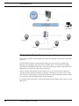
TruVision SVR is the software-based recorder platform for the TruVision product family, giving the
flexibility of commercial-off-the-shelf server support for scalable video recording needs.
TruVision Navigator is the interface used to view and manage the data recorded in the TruVision SVR
system. TruVision Navigator v5.0 or a later version is required to manage TruVision SVR. Data can
be accessed and viewed over a LAN or the Internet. Through remote viewing and management of
third-party cameras, TruVision SVR expands the flexibility of corporate security systems.
TruVision SVR, utilizing the technology of IP-addressable cameras, allows system operators to
access and program their cameras from anywhere in the world. These network digital video cameras
are designed specifically for remote monitoring and management applications such as security and esurveillance.
All IP cameras must have their IP addresses configured according to their respective user guide(s).
The IP addresses may also be entered when configuring the camera in the TruVision Navigator
management software.
Once SVR is installed on a system and the system is in production, it is recommended that security on
these servers should be locked down by the system administrator so that only users with valid
Windows domain accounts have access to video. With the introduction of the browser-based
applications, the ability to access video servers is made much easier using Microsoft domain
authentication. It is highly recommended to deny access to these servers for a secure deployment.
TruVision SVR System User Guide
9
TruVision SVR Overview
TruVision SVR Configuration
Storage Space Reservation
TruVision SVR content is stored in separate tracks that contain information on the index, video status,
and events.
TruVision SVR always keeps a certain amount of disk space reserved to be in accordance with
Microsoft’s drive guidelines. Ten percent of the overall disk space is reserved for these guideline
requirements and an additional ten percent is reserved for event storage. In total, twenty percent of the
hard disk space is already in use and cannot be used freely.
Because TruVision SVR content is stored in separate files if even one of those files is deleted or
corrupted video may become inaccessible. For instance, if the index track no longer exists you may
not be able to use video tracking. It is advisable to follow basic backup and security measures to make
sure your data is protected against hardware and network failures.
If your video becomes inaccessible, contact the Interlogix Technical Support Group to assist you with
data recovery.
10
TruVision SVR System User Guide
Digital Video Prerequisites
Digital Video Prerequisites
Time Synchronization
For digital video system to work properly, time must be synchronized on all computers. Third-party
tools are available to synchronize times across multiple time zones. If no NTP source is available,
TruVision Navigator server can be used as the NTP server.
Anti-Virus Software
If this type of software is required (due to corporate policy, for instance), then you must adhere to the
following guidelines:
•
For Real-Time protection, you must exclude all files with the extensions .SPFS, .INFO, .LVI,
.LEI, and .LNR.
•
For Real-Time protection and virus scan, you must exclude the data drives.
Windows Updates
When running Windows updates, be aware that they require a full shut down of your computer. Make
sure that these updates are scheduled to run when either recording will not be necessary or when
backup or fail over systems are properly configured and running.
Storage File Purging
If the system runs out of hard disk space while the system’s cameras are configured for storage
capacity, the oldest video files are deleted regardless of what camera they are on. In addition to video
files, TruVision SVR content is stored in separate tracks that contain information on the index, video
status, and events.
This can lead to potentially problems if not accounted for. For example, consider a case where the
retention policy is set to five days for all channels, except for one channel which is configured for a
30-day retention policy. The reclamation logic will reclaim files for the channel with 30 day retention
that are 6-30 days old before reclaiming files from any other channel. This would significantly affect
the amount of video that would be stored for the 30 day retention channel.
TruVision SVR System User Guide
11
TruVision SVR Overview
12
TruVision SVR System User Guide
CHAPTER 2
TruVision SVR Network
Configurations
It is very important that all computers on the TruVision SVR Network are on the same domain or
trusted domain. If they are not, the TruVision SVR will not function properly.
Network Configuration
The following firewall and permission information needs to be configured correctly for the TruVision
SVR to work correctly.
Windows Firewall
By default, the Windows firewall is enabled. The system administrator must determine whether
firewall services are used on their system. If the firewall is enabled, it will prevent the security
management system software from functioning properly until certain things are added to the
exception list, which defines which components and ports should not be blocked by the firewall. If
the firewall is enabled during installation of the security management system software, the exception
list will be automatically populated.
IMPORTANT:
Since certain elements are added to the exception list, it is mandatory that the
Don’t Allow Exceptions check box on the General tab of the Windows
Firewall dialog is not selected.
Windows Firewall Settings
Exception List:
• TruVision SVR services:
• LnrCapSvcu
• LnrRetrSvcu
• LnrRTPServer
• LpsSearchSvc
• RPC Port (TCP/IP 135)
• RTP Port (TCP/IP 554)
TruVision SVR System User Guide
13
TruVision SVR Network Configurations
• UDP Port (5000)
ICMP Settings:
• Allow incoming echo requests
Windows Authentication Model
The process used by Windows to verify a client’s identity is called authentication. In order to properly
set up a system or troubleshoot an existing installation, the first step is to determine the identity of the
client attempting to connect to the server.
Here are some general guidelines:
• Interactive processes always run with the identity of the user that launched them, or they can be
launched with credentials of a different user through the “runas” command.
• Services typically run under the SYSTEM account (or another account specified through
Windows Services).
When a client connects to a remote server, the client’s identity is sent to that machine, and that system
authenticates the client. This process can have several outcomes depending on which user account is
used by the client:
• If both machines are in a domain and the domain user is used, then the server will use the domain
controller to authenticate the incoming client connection.
• If the client used the local machine account and the same local account with the same password
exists on the server, then that account will be used.
Note:
If the same local account exists on the server, but the password is different, the client’s
connection attempt will immediately return failure. It will not default to the method
described next.
• If the client used the local machine account and an account with that name is unknown to the
server, an incoming connection will be assigned the ANONYMOUS user on the remote machine.
Note:
There is a security policy which allows ANONYMOUS users to be part of the
EVERYONE group, but by default the EVERYONE group only includes users whose
identity was established in some way (i.e., not anonymous).
Local vs. Remote Permissions
Extended Windows security model, introduced in Windows XP SP2 and Windows 2003 Server SP1,
split permissions listed in the previous section into two separate parts: local and remote. This allows
system administrators more granular control over object security.
As the client-server connection is analyzed, the location of the components will determine which
permissions (launch, activation, and access) will be used. If both components are running on the same
machine, local permissions will be used. Otherwise, Windows will use remote permissions.
14
TruVision SVR System User Guide
DCOM Configuration
DCOM Configuration
The DCOM settings must be the same on all computers connected to the TruVision SVR. Be sure to
close all security management system applications that may be connected to the recorder.
1.
2.
3.
4.
5.
6.
7.
8.
9.
In Windows, from the Start menu select Run
Type dcomcnfg and click [OK].
Access the Distributed COM Configuration Properties by navigating to Component Services >
Computers > My Computer.
Right-click on My Computer and select Properties.
On the Default Properties tab, make sure it is configured as follows:
• Select the Enable Distributed COM on this computer check box.
• Clear the Enable COM Internet Services on this computer check box.
• Default Impersonation Level should be set to “Impersonate.”
• Clear the Provide additional security for reference tracking check box.
On the Default Protocols tab, use the buttons to order the list in the exact order shown below:
• Connection-oriented TCP/IP
• Datagram UDP/IP
• Tunneling TCP/IP
• Connection-oriented SPX
Click [OK].
If changes were made, restart the recorder.
Verify that the object exporter error does not appear. If the error still occurs, repeat this
procedure, but in step 6, remove the Tunneling TCP/IP protocol from the list of default protocols.
TruVision SVR System User Guide
15
TruVision SVR Network Configurations
16
TruVision SVR System User Guide
CHAPTER 3
TruVision SVR Installation
TruVision Software Video Recorder
The TruVision SVR is a network recorder designed to store video obtained from IP cameras. When
configuring the IP cameras, be sure to configure the correct IP address in the client software.
Two network cards may be installed on the TruVision SVR system. When using a second network
card to connect to a network independent from that of the host system, the second network must have
a different subnet.
TruVision SVR Firmware
In order for the recorder to work, the correct version of firmware must be installed on the machine.
Before installing the TruVision SVR firmware, DirectX should already be installed. If not, the
TruVision SVR setup will stop so that you can install DirectX.
TruVision SVR System User Guide
17
TruVision SVR Installation
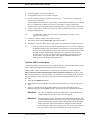
System Hardware Requirements
Component
Minimum
Recommended
High
Notes
Below configuration is
tested to support 32 IP
cameras recording at 4CIF
resolution with 30fps, 50%
compression, and motion
detection enabled. (82%
CPUUtilization)
Below configuration is
tested to support 32 IP
cameras recording at
4CIF resolution with
30fps, 50%
compression, and
motion detection
enabled. (56% CPU
Utilization)
Below configuration is
tested to support 64 IP
cameras recording at
4CIF resolution with
30fps, 50%
compression, and
motion detection
enabled. (68% CPU
Utilization)
Processor
Intel Core I5-2400
Xeon X3450 2.66GHz
Dual Xeon E5620
3.10GHZ 6MB L3
8MB Cache 2.5 GT/s
2.26GHz 5.86 GT/s
Cache Quad Core
Quad Core Processor
Quad Core
Processors
4GB DDR31333MHz
4GB DDR3 1333MHz
6GB DDR31333MHz
NECC UDIMMs
NECC SDRAM
NECC SDRAM
250GB - 7200RPM,
500GB5 - 7200RPM,
500GB5 - 7200RPM,
SATA 3.0Gb/s, 16MB
SATA 3.0Gb/s, 16MB
SATA 3.0Gb/s, 16MB
Cache
Cache
Cache
Integrated PCIE
Integrated PCIE
Integrated PCIE
10/100/1000
10/100/1000
10/100/1000
Processor
Memory
Hard Drive (OS)
Network
Supported Operating Systems
•
•
•
•
•
•
•
Windows Server 2003 SP2 Standard and Enterprise
Windows Server 2003 R2 with SP2 Standard and Enterprise
Windows Server 2008 SP2 32-bit
Windows Server 2008 SP2 64-bit
Windows Server 2008 R2 with SP1 Standard and Enterprise
Windows 7 SP1 32-bit
Windows 7 SP1 64-bit
TruVision SVR Configuration
1.
Download the TruVision SVR installation package and run the setup.exe program on the system
SVR is intended to work on.
Note:
2.
3.
4.
18
It is strongly recommended that TruVision SVR and TruVision Navigator are installed
on separate machines.
Click [Install] to install the prerequisites and once it is completed, click [Next].
Read the license agreement. If you agree, select the appropriate radio button. Click [Next].
Select the destination folders and click [Install].
• TruVision Software Video Recorder log files are stored at the following location for
Windows 7: C:\ProgramData\UTC Fire & Security\TruVision SVR\logs
TruVision SVR System User Guide
TruVision Software Video Recorder
5.
Click [Next].
After the installation is complete, the SVR Management Console is displayed. This dialog is used
to configure the location of data for the network recorder.
a. Under Available locations, all local harddrives and mapped network drives are listed. Select
a drive and click the arrow key to move the selection to the other column (Selected
Locations).
• If you are using network drives, it is recommended that a user account be created to
access those network drives.
• Mapped drives appear in the Available locations list, but will not function properly and
should not be used.
• To specify a universal naming convention path name, click <Other Location>. You
will then be presented with the option to type in the path or browse for the location.
• The following are supported:
iSCSI: Internet SCSI (Small Computer System Interface), an IP-based storage
networking standard for linking data storage facilities. Because of the ubiquity of IP
networks, iSCSI can be used to transmit data over LAN, WAN, or the Internet and can
enable location-independent data storage and retrieval.
SAN: (Storage Area Network). A high-speed special-purpose network (or subnetwork)
that interconnects different kinds of data storage devices with associated data servers on
behalf of a larger network of users.
NAS: (Network-Attached Storage). A hard disk storage that is set up with its own
network address rather than being attached to the department computer that is serving
applications to a network’s workstation users.
IMPORTANT:
b.
c.
Note:
6.
7.
8.
When recording to NAS, keep in mind that failures may occur due to lack of
bandwidth, or poor harddrive performance (for example, if several TruVision
SVRs are writing to the same drive location or same shared folder).
Each recorder requires its own dedicated space for storage.
Specify the name of the folder where the data is to be stored. If the name of the folder
specified does not already exist, it will be created.
Enter the amount of free space (in MB) to be maintained on each drive. If this field is left
blank, no free space will be maintained. The network recorder will always continue to record
by deleting the oldest video files if drive space becomes depleted.
It is recommended to leave 10% of each storage drive free. Lower values may
negatively affect the performance of the recorder.
d. Click [Next].
The Security tab is used to display the current security settings applied, as well as the required
actions that need to be applied on the machine in order for SVR to operate successfully. Click
[Apply] to apply required Storage and Security settings.
The Results tab will display the status of the actions applied in previous steps.
Once you are finished installing the network video recorder, click [Finish]. If you wish to make
changes to these settings, you may do so at a later time from directory C:\Program Files\UTC
Fire & Security\TruVision SVR\SVR Management Console for a 32 bit system, or,
C:\Program Files(x86)\UTC Fire & Security\TruVision SVR\SVR Management Console for
a 64 bit system.
TruVision SVR System User Guide
19
TruVision SVR Installation
Adding TruVision SVR to TruVision Navigator
After the installation is completed, TruVision SVR needs to be added to the TruVision Navigator
device tree. To add an SVR to the Navigator, follow these steps:
1.
Click [Add Device] button and Select [Add Manually].
Note:
2.
3.
4.
5.
6.
7.
Embedded discovery tool in Navigator does not support discovery of SVR.
Select [SVR] from the drop down menu for the Device Type.
Enter desired name for the [Device Title].
Enter [IP Address] of the TruVision SVR server.
Enter 554, or any other port, for [Device Port]. (Ports other than 554 need to be set on the SVR
system as well.)
Click [Ok].
Click [Yes] and follow the instructions to install SVR Client Components.
Note:
To connect to the SVR for the first time, each TruVision client needs to install the SVR
Client Components.
Note:
With each TruVision Navigator client upgrade, SVR Client components must also be
updated. Before removing existing SVR Client components from the client machine,
make sure all the SVRs are deleted from the device tree. It is recommended to export
the address book so it becomes easier to import the devices back to the Navigator after
installing the new SVR client components.
Note:
TruVision SVR must be activated via TruVision Navigator with the appropriate licenses
within the first 30 days trial period. The SVR and the cameras recording to it will not be
accessible after the trial period until the TruVision Navigator server is updated with the
appropriate type and amount of licenses.
Licenses
TruVision Navigator has a licensing interface embedded in the help screen. The licensing link will
display the Licensed Features window for managing the TruVision SVR recorder base and camera
licenses. The Update license button will provide the license management screen where a user can
change the required licenses and add more licenses via a new license key purchased from Interlogix.
TruVision SVR Licenses are obtained from Interlogix customer service. There are three types of
TruVision SVR licenses available:
• TruVision SVR Base License (TVS-BASE): Required for each TruVision SVR recorder
• TruVision SVR 3rd party Camera License (TVS-CAM): Required for each individual 3rd party
camera
• TruVision SVR Interlogix Camera License (TVS-CAM-ILX): Required for each individual
ILX camera
Obtain Licenses
To obtain licenses, follow these steps:
1.
20
Click [Help] on the tasks toolbar of TruVision Navigator.
TruVision SVR System User Guide
Adding TruVision SVR to TruVision Navigator
2.
3.
4.
5.
Click [Licensing] to see the licensed features.
Click [Update License]. A new window will appear.
Enter the number of licenses needed for each SVR server, 3rd party cameras, and Interlogix
cameras to the related fields.
As these quantities are entered, the “Customer Key” will be updated automatically. A “Customer
Key” is a combination of Unique TruVision Server ID, number of SVRs installed to the
TruVision Server, and number of Interlogix and third part party cameras installed to the system.
Use the “Customer Key” on the screen to place the order for purchasing a license key from the
Interlogix channel partner.
Note:
“Customer Key” will be used as a reference when Interlogix customer service
generates your license key.
7.
A license key will be e-mailed to the address provided.
Enter the key received in the License Key field, and click [OK].
8.
All SVR servers and IP cameras in the system will be activated after following previous steps.
6.
Note:
Interlogix cameras, third party cameras, and SVR physical servers can be swapped by a
comparable product as long as the number of licensed devices in TruVision Navigator
Server is not exceeded. Applied licenses create a pool of device groups (SVR recorders,
Interlogix cameras, and third party cameras) that are supported by that TruVision
Navigator Server. Licenses can only be entered and applied on TruVision Navigator
Server machine. TruVision Navigator Clients pull the available licensed device
information from the TruVision Navigator Server.
TruVision SVR Live Video Setup
The TruVision SVR Live Video Setup is a tool installed with the TruVision SVR Installer. It can be
used to enable and configure multicast protocol and limit port ranges.
On the recorder, run the TruVision SVR Live Video Setup tool (LnrNI.exe) from c:\Program
Files\Common Files\Lenel Shared\LNVSuite Client Components\7.0\LnrNI.exe. If there is more
than one network interface, select the interface you would like to use for sending multicast. Run the
TruVision SVR Live Video Setup tool on each client workstation using monitoring software to see
live video.
1.
2.
3.
Select the Use Multicast checkbox.
If more than one network interface is detected, select the interface to be used for receiving live
video.
If there is a firewall between the recorders and the client, certain ports must be open for
Multicast/UDP. Select the Use ports checkbox. Type in the ports to be opened on the firewall.
IMPORTANT:
On routers, IP Multicast must also be enabled. Refer to the manufacturer to
enable IP Multicast. This may require a firmware upgrade.
IMPORTANT:
Firewalls between the TruVision SVR and its clients usually block both UDP/
IP and IP Multicast traffic. This traffic is one-directional communication, so if
there are firewalls, they must have traffic enabled going from the TruVision
SVR to the clients. If the firewall cannot be configured to enable UDP/IP
traffic on all ports, then specify a range of ports to be opened. The number of
live video streams on the client is limited by the number of open ports.
TruVision SVR System User Guide
21
TruVision SVR Installation
Note:
Some network devices such as routers and switches may broadcast it to all devices
instead of delivering data only to subscribed clients. Slow (10 Mbps) devices cannot
handle the traffic. It may be possible to resolve these issues by using 100 Mbps or
higher devices.
The following tabs allow you to limit the port range that are used for the sections specified:
•
Client Network Settings
•
Recorder Network settings
•
IVS Network Settings
•
Remote Monitor Network Settings
•
RTP Client settings
Uninstall TruVision SVR Firmware
1.
2.
Remove the TruVision Software Video Recorder from the computer.
Delete the following folders from the computer:
• C:\Program Files\TruVision SVR
• C:\Program Files (x86)\UTC Fire & Security\TruVision SVR (for 64 bit OS)
• C:\ProgramData\UTC Fire & Security\TruVision SVR for Windows Vista or later
IMPORTANT:
3.
Open the Registry Editor and delete the following entries:
• hkey_local_machine\software\Lenel
• hkey_local_machine\software\microsoft\MSSQLService
• hkey_current_user\software\Lenel
Note:
4.
Modifying the registry could cause irreversible damage to your Windows
operating system; be sure to back up the registry before making any changes.
Follow the instructions located at: http://support.microsoft.com/kb/322756.
Some keys may not be installed, depending on the version of TruVision SVR firmware.
Restart the computer.
TruVision SVR Unattended Upgrade
TruVision SVR is a Windows Installer-based setup package capable of running upgrade installations
in reduced user interface modes to support various industry standard deployment technologies, such
as SMS or Active Directory. This section provides specific requirements for deploying the TruVision
SVR via unattended or silent methods.
Deploying Prerequisites
There are several third-party prerequisites that are required prior to the TruVision SVR upgrade.
These applications are installed during the standard user-driven installation; however when running
the installation in reduced user interface modes these prerequisite requirements must be met prior to
22
TruVision SVR System User Guide
Adding TruVision SVR to TruVision Navigator
the TruVision SVR installation. These applications can be found on the TruVision SVR disc and
deployed individually using your preferred unattended technology.
Third-party Prerequisites
Application
TruVision SVR Disc Location
Recommended
Commands
Microsoft .NET
4.0 Runtime
.\ISSetupPrerequisites\{074EE22F-2485-4FED-83D1AAC36C3D9ED0}\dotnetfx35.exe
/v /q /norestart
Microsoft XML
Parser 6.0
.\ISSetupPrerequisites\{726F97A8-63B9-4A58-ACFBB8A56B383740}\msxml6_x86.msi
/qn
Microsoft C++ 8.0
Runtime
.\Temp\VCPP9Runtime\vcredist_x86.exe
/q
Microsoft C++ 9.0
Runtime
.\Temp\VCPP8Runtime\vcredist_x86.exe
/q
Intel Performance
Primitives 5.2
.\Temp\INTEL\w_ipp_rti_ia32_p_5.2.msi
/q
Deploying the TruVision SVR
The TruVision SVR is a standard Windows Installer-based package capable of low user interface
mode switches for unattended deployment, such as /qr. The installer package requires some user input
from a configuration file and a command flag.
Configuration settings used in an unattended upgrade are stored in the lnrsetup.ini file located in the
Unattended Installation folder on the TruVision SVR disc. This file contains instructions for the
various available configuration settings. The file must be modified for your specific system needs
prior to deploying the TruVision SVR via unattended mode. Once the file has been updated, it can be
stored on a disc or network location so that it can be passed to the setup during the unattended
installation.
It is recommended to use the /qr parameter to run the installation package in quiet reduced mode via
your chosen deployment technology. The UNATTEND flag must also be used to specify the fully
qualified path of the lnrsetup.ini file.
The following is an example call to the Windows Installer engine (msiexec) which runs the install
command (/i) on the TruVision SVR setup package. In this example, the package will be run in
reduced quiet reduced mode (/qr) and the UNATTEND parameter specifies the full path to the
location of the lnrsetup.ini file. The package and settings are hosted on an accessible Web server so
that they always have the same relative access path when they are deployed.
"C:\Windows\system32\msiexec.exe /i "\\MyNetworkServer\Lenel
Network Video Suite.msi" /qr
UNATTEND=""\\MyNetworkServer\MyLNVRSettingsFile\lnrsetup.ini"
After the upgrade is complete, reboot the TruVision SVR and verify that it has returned online in
monitoring software.
TruVision SVR System User Guide
23
TruVision SVR Installation
PTZ Control
Refer to your specific camera user guide to see its specific PTZ Control capabilities. To see specific
camera capabilities, please refer to www.interlogix.com.
PTZ Connections
PTZ devices without a built-in IP device require a serial connection to an IP camera or video server
(via RS-232, RS-485, or RS-422 standard). For more information, refer to the manufacturer’s
documentation.
PTZ Device Configuration
PTZ devices with built-in IP cameras do not require special configuration. For all other cases, use the
IP device’s web interface to configure the appropriate settings for the driver and COM port (baud rate,
data bits, stop bits, parity bits).
24
TruVision SVR System User Guide
TruVision Software Video
Recorder
CHAPTER 4
TruVision SVR Capabilities
The following chapter discusses features and capabilities of a TruVision SVR system.
TruVision Navigator support
TruVision SVR is supported by TruVision Navigator 5.0 and later releases. Refer to the TruVision
Navigator User Manual for more information on specific functions described.
Configurations Menu and Capabilities
Health Diagnostics
TruVision SVR is able to provide health diagnostics information via TruVision Navigator. To obtain
this information, right-click on the SVR in the TruVision Navigator device tree, and select “Health
Diagnostics.” This information is also summarized in export enabled device report. The following
information can be obtained with this report:
• Network information: IP address.
• System Information: SVR firmware version, recorder date & time, live connection limits,
playback connection limits.
• System Health: Device status.
• Recording: Recording disk location, recording capacity left, recording capacity protected,
recording retention period.
Camera Configuration
TruVision SVR is able to configure cameras via the device configuration window in TruVision
Navigator interface. To do this: right-click on SVR and select [Configure Device].
TruVision SVR System User Guide
27
TruVision SVR Capabilities
Various settings can be applied to the camera including picture settings, camera settings, event
management, and audio input settings.
Camera status can be checked and updated with [Get Camera Status] button in this menu.
Motion Detection (AI)
TruVision SVR is able to detect moving objects or people within the camera’s field of view. Motion
detection can be customized to:
• Detect motion in only certain regions of the camera’s view.
• Configure the movement threshold that must be met in order to generate an alarm.
Note:
Since the Motion Detection Grid of the SVR in the configuration window is a function
of the SVR itself, a grid set in the SVR configuration will not be reflected in the
camera’s own motion detection settings.
Configure Motion Detection
To setup motion detection in the Navigator interface, please follow these steps:
1.
2.
3.
4.
5.
6.
7.
8.
9.
10.
In the Services menu, click [Start] to begin the notification processor.
Right-click on the IP camera and select “Configure Camera.”
On the Video sub-tab, enable the Motion Detection check box.
Click [Grid button]. The Motion Grid Setup window opens.
Right-click on the image and select “Select All.” Or click and hold the left mouse to select the
specific area(s).
Select a schedule.
Select “Normal” for recording.
Select “On” for Alarm.
Select a sensitivity level between 0-100.
Click [OK] to save. Once these steps are completed, the bell icon should turn to red with motion
events.
Note:
It may take a couple minutes for changes to take effect. Refresh the alarm list until the
first alarms are populated.
Camera Tampering
TruVision SVR is able to detect when the camera cannot view an area due to a tampering activity. An
alarm is generated if the camera cannot focus on the scenery within the camera’s field of view but
does detect a solid color image. This is used primarily to alert monitoring stations that a camera has
been compromised by being covered.
Brightness Change
TruVision SVR is able to detect lighting changes within the camera’s field of view. If the lighting
changes from bright to dark or vice-versa an alarm is generated.
28
TruVision SVR System User Guide
Configurations Menu and Capabilities
Recording Configuration
TruVision SVR also configures the recording settings of the cameras via the device configuration
window in TruVision Navigator interface.
Right-click on SVR and select [Configure Device] and select [Recording] tab.
Various settings including recording mode, event recording mode, and compression settings can be
applied to the camera with this interface. For more information, refer to Chapter 5: Cameras on
page 31.
Event recording
Event recording allows a camera to be configured for a higher frame rate when an event is generated.
The camera can also be configured for pre-roll or post roll on an event so that video is recorded at the
higher frame rate a few seconds before and after the event occurs. After the event restores and any
amount of post roll recording has passed, the camera returns to the normal recording mode that was
set prior to the event.
Event recording is fully supported for MJPEG and MPEG4, but with H.264 the event recording frame
rate has to be set to the normal recording frame rate. MPEG-4 can also record I-frames on non-event
and then record at the normal frame rate when an event occurs.
Notifications
TruVision SVR configures notifications for specific events such as Network usage, CPU usage, and
Disk Busy status with appropriate thresholds. To do this: right-click on SVR and select [Configure
Device] and select the [Notifications] tab.
Various storage notifications can be set up in this menu.
To set up a retention period, select “Automatically delete video older than date” and enter the desired
number in the Days field.
System Settings
TruVision SVR provides and configures key system settings such as basic system information,
recording capacity parameters, and storage statistics. Right-click on SVR and select [Configure
Device] and select [System] tab.
Limits can be set for live clients and recorder clients from this interface.
Schedules
TruVision SVR can record based on schedules. To set the schedules, right-click on SVR and select
[Configure Device]. Schedule options are on the System tab. Default schedules in TruVision SVR
are:
• Never - disables scheduled recording.
• Always - enables 24/7 continuous or event based recording based on the recording mode selected.
TruVision SVR System User Guide
29
TruVision SVR Capabilities
Network storage
A TruVision SVR can be set to record video to a network storage location which the TruVision SVR
will treat as another local storage drive. To select a network attached storage (NAS) for recording,
launch the SVR Management Console from the Windows Start menu. In the SVR Management
Console, select the storage tab to make the changes.
A full list of features is provided in the Device Feature Matrix chart located on the TruVision
Navigator webpage at www.interlogix.com.
30
TruVision SVR System User Guide
CHAPTER 5
Cameras
For a list of currently supported cameras, visit: www.interlogix.com/video.
Supported Camera Functionality
The following list of settings can generally be configured on the cameras currently supported by
TruVision SVR. However, not all cameras listed support all listed functionality.
Audio
Specifies whether Audio is implemented on this camera (Audio incoming from the camera to the
recorder). Selecting “Yes” denotes that Audio is supported and is recorded on the TruVision SVR.
Audio Source Types
Allows the user to select the audio source type. The audio source type is based on the individual
camera. Refer to the camera manufacturer’s user guide for information about available audio source
types. Source types can typically be “line” or “microphone”.
Audio Volume
Allows for volume control of the camera’s incoming audio.
Backlight Compensation
Allows the user to adjust the camera’s backlight compensation.
Brightness
Allows the user to adjust the camera’s image Brightness.
TruVision SVR System User Guide
31
Cameras
Camera Motion Detection
Specifies whether the camera supports Camera Motion Detection and if it’s used as part of the
schedule.
Change Password Capability
Specifies whether the user can change the password on the camera via the software.
Contrast
Allows the user to adjust the camera’s image contrast.
Exposure
Allows the user to adjust the camera’s image exposure or the amount of time light is allowed to pass
through the camera lens.
Firmware
Indicates the firmware of the camera that this version of TruVision SVR is tested and supported with.
Frame Rates
Indicates the available frame rates (frames per second) allowed to be specified in the software for that
camera.
Gamma
Allows the user to adjust the gamma of the camera output.
H.264
Specifies whether this camera supports the H.264 standard.
Hue
Allows the user to adjust the camera’s image Hue.
IO Inputs
Shows the number of inputs, if any, that can be configured for that camera type.
IO Outputs
Shows the number of outputs, if any, that can be configured for that camera type.
MPEG4
Allows the user to put the camera in MPEG4 mode, which records video using MPEG4 standards.
32
TruVision SVR System User Guide
Supported Camera Functionality
Multiple Video Inputs
Specifies whether the camera is a multiple video input camera (typical a 4 channel encoder).
Name
Specifies the name of the camera as given by the user.
PTZ
Allows the camera to be controlled via pan, tilt zoom functionality of the video viewing software.
Quality
Allows the user to adjust the camera’s image quality.
Recording on Camera
Allows the user to configure recording to the internal storage of a camera if supported by the camera.
Resolutions
Specifies the available resolutions supported for this particular camera type. The resolution may
change based on the standard used and the codec.
Rotation
Allows the user to rotate the camera at 90 degree intervals.
Saturation
Allows the user to adjust the camera’s image color saturation or color level.
Sharpness
Allows the user to adjust the camera’s image sharpness.
Supports Digest Authentication
Specifies whether the camera supports Digest Authentication along with Basic Authentication.
Two-Way Audio
Specifies whether the camera can be used for bidirectional audio communications.
Video Standards
Specifies the standards (i.e. NTSC, PAL) supported by the camera.
Note:
If cameras are added via the discovery tool in TruVision Navigator, the default for video
standard setting is NTSC.
TruVision SVR System User Guide
33
Cameras
White Balance
Allows the user to adjust the camera’s image white balance.
Adding Cameras to SVR
There are two ways to add IP Cameras to a TruVision SVR server:
• Adding manually
• Adding from the list of discovered devices
Add Cameras to an SVR Recorder with the Discovery Tool
Adding IP cameras from the device discovery list is a convenient way to assign single or multiple
cameras to an SVR recorder.
1.
2.
3.
Right-click on the SVR in TruVision Navigator device tree
Select [Add IP Cameras], and click [Add via Device Discovery]. The Device discovery window
will appear.
Select the IP camera(s) to be added to the TruVision SVR and click [Add].
Note:
Only cameras supported by that recorder will be discovered. Also, cameras assigned to
a recorder will not be shown in this list.
Note:
The Discovery Tool will attempt to add devices by using their default credentials. If the
credentials of a device were previously changed from default values, the device is still
going to be added to the device tree and SVR, but will be shown as offline. In this case,
updated credentials need to be applied manually by the user from the device properties
or configuration menu with a right-click on the device.
Add Cameras to an SVR Recorder Manually
Adding IP cameras with the “Add Manually” option gives user the ability to assign cameras to SVRs
in a traditional way.
Note:
3.
Right-click on the SVR in TruVision Navigator device tree
Select [Add IP Cameras], and Click [Add Manually]. A new window will appear.
Fill the fields with the related IP camera information
4.
Click [OK].
1.
2.
34
Cameras with a “+” sign refer to the alternate stream of the camera. For low bandwidth
environments, these cameras may be added to the SVR instead of adding the primary
stream.
TruVision SVR System User Guide
CHAPTER 6
Secure TruVision SVR Installation
Checklist
This chapter describes the steps for making the TruVision SVR installation more secure. The
intention of this chapter is not to cover general Windows security practices and guidelines, but to
assist IT professionals in applying these practices and guidelines to Interlogix video products.
Limit Access to the Users Group
By default, TruVision SVR is installed with access granted to all clients. Access includes retrieval of
video and the ability to modify the recorder configuration. Access can be limited by running LnrSetup
and opening the Security tab.
Review Machine-Wide DCOM Security Settings
Default machine-wide limits should be adjusted to provide adequate security for the Windows
installation. Each product in the Video Suite has different DCOM configurations based on the
included components.
If access to TruVision SVR is limited to the LNRUsers group, then anonymous user and everyone
entries do not have to be given access. Removing these entries from access permission limits and
launch/activation limits will improve security. The LNRUsers group must be allowed to access and
activate DCOM objects, but not launch them.
If access to the TruVision SVR is not limited to the LNRUsers group, anonymous user access can still
be disabled. With this setting, only users that the system knows about will be able to authenticate.
This could be problematic for installations that do not have a domain server. Therefore the
recommendation is that if the TruVision SVR is secured with this method, then the TruVision SVR
and all client machines should be part of a domain.
TruVision SVR System User Guide
35
Secure TruVision SVR Installation Checklist
36
TruVision SVR System User Guide
CHAPTER 7
Device Discovery and
Management
For a list of currently supported cameras, visit: www.interlogix.com.
Device Discovery
The Device Discovery tool provides an easy way to discover the devices and make them ready for
recording in the system. Device discovery tool is available via various paths in TruVision Navigator,
and is used for discovering recorders, cameras, and encoders in the network.
Following is the path to discover and add cameras to SVR:
Adding Cameras to SVR
Note:
The SVR does not have a discovery protocol embedded. Therefore, SVR won’t be
discovered when the network is searched.
• Select one or multiple cameras from the discovered devices list, and click [add].
• Right-click on an SVR in the device tree, click [Add IP Cameras], and select [Add via Device
Discovery].
Device Management
Device Management tool provides various information and functions to ensure the ease of system
setup and maintenance. To access to the device management interface, right-click [Devices] and
select [Device Management].
The discovery tool window includes following areas and device management functions
• Device List
• Assigning IP Address to a device
• Pinging device(s)
TruVision SVR System User Guide
37
Device Discovery and Management
•
•
•
•
Rebooting device(s)
Getting Firmware Version of device(s)
Opening Web Page of a device
Checking default credentials of device(s)
Device List
Provides a list of devices in the network. For convenience, devices can be grouped together by their
type or brand. The list can also be sorted by one of the columns by keeping the selected groupings.
‘Connected To’ column provides the information on the recorder each camera is recording to.An
empty field indicates that the camera is discovered in the network, but is not assigned to a recorder
yet.
Device list also provides the following device information: Model Name, IP Address and Port,
Subnet Mask, Firmware Version, MAC ID, and Serial Number.
In addition, the Status column provides the results of the Ping, Assigning IP Address, Get Firmware
Version, and Reboot commands.
Assign IP Address
Allows the users to assign an IP address to a camera.
1.
2.
3.
Select a camera from the device discovery list.
Click [Change IP Address].
Enter the [New IP Address] to the related field, and click [Ok].
Ping
Allows the users to ping device(s) to check the link activity. Status of the ping command is given in
the Status field.
Reboot
Allows the user to remotely reboot device(s) with one click. Status of the reboot command is given in
the “Status” field.
Opening Webpage of a Device
Allows the user to open the web browser menu of a device.
Checking Default Credentials of a Device
Allows the user to check if device credentials are changed from the default values.
38
TruVision SVR System User Guide
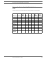
Discovery Tool Feature Capability Matrix by Camera Model
Discovery Tool Feature Capability Matrix by Camera
Model
The Device Discovery Tool currently supports the following functions for each manufacturer.
Device List
Discovery
Launch
Device
Website
Interlogix
y
y
Axis
y
y
y
y
Sony
y
y
y
y
Panasonic
y
y
y
y
Arecont
y
y
y
y
IQ in Vision
y
y
y
y
Bosch
y
y
y
y
Mobotix
y
y
y
y
TruVision
Encoders
y
y
y
y
TruVision
Recorders
y
y
y
y
TruVision SVR System User Guide
Ping
Check
Default
Password
Change
Device
Password
y
y
y
y
y
y
Assign
IP
Reboot
y
39
Device Discovery and Management
40
TruVision SVR System User Guide
CHAPTER 8
Recovery Tool
The TruVision SVR Recovery Tool is used to restore system information that may have been lost as a
result of upgrading from an earlier version of TruVision SVR to TruVision SVR 7.0.825 or from
removing storage locations containing SVR files. Without this system information the video will not
be viewable on a TruVision Navigator client until the recovery tool is run.
The recovery tool can be run while the TruVision SVR is either recording or not recording. If the
TruVision SVR is still recording while the recovery tool is run, older video will not be accessible to
TruVision Navigator and the recovery tool will take longer to finish then if the TruVision SVR is not
recording.
Recover Video Files
1.
2.
3.
4.
IMPORTANT:
Running the TruVision SVR Recovery Tool will cause services to stop and
restart, which will cause video monitoring to stop for several minutes.
IMPORTANT:
The TruVision SVR Recovery Tool must be run on each TruVision SVR where
video will be viewed on TruVision Navigator.
IMPORTANT:
If the TruVision SVR is heavily utilized the recovery tool may take a long time
to execute.
Navigate to C:/Program Files(x86)/Interlogix/TruVision SVR/ and run the
LnrRecoveryConsole.
The tool will automatically detect the recorder on the TruVision SVR. Click [Start].
The tool will process the recorded videos in the TruVision SVR. If the TruVision SVR services
are running the tool asks if it is okay to automatically stop and start the services as needed. Click
[Yes] to continue the recovery process. The more video that needs to be recovered the longer the
tool will take to run.
Optionally, you can schedule the specific day and time during the week that the tool will run.
TruVision SVR System User Guide
41
Recovery Tool
42
TruVision SVR System User Guide
Index
A
Anti-virus software ......................................... 11
C
TruVision
SVR Capabilities .................................... 27
SVR Installation ...................................... 17
SVR Network Configurations .............. 13
Cameras ............................................................ 31
D
DCOM configuration ..................................... 15
DCOM Settings
TruVision SVR ........................................ 35
Digital video ............................................. 13, 41
prerequisites ............................................. 10
E
Event recording ............................................... 29
F
Firmware .......................................................... 17
uninstall .................................................... 22
L
Licenses ............................................................ 20
N
Network
configuration ............................................ 13
P
PTZ
control ....................................................... 24
T
Time synchronization ..................................... 11
TruVision SVR System User Guide
43
Index
44
TruVision SVR System User Guide