1
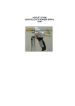
Ford C6 Cable Operated Shifter Installation Instructions
Building American Quality… With A Lifetime Warranty! ®
TOLL FREE 1-877-469-7440 • [email protected] • www.lokar.com
5/16"-24 x 1/2"
Button Head Bolts
Ford C6 Cable Operated Shifter
Installation Instructions
Aluminum
Adjuster Plug
5/16" Lock Washers
Floor
Mount
Tabs
General Installation Notes:
Please read these instructions completely before beginning the installation.
If you have any questions please call.
5/16"-24 Nylock Jam Nuts
5/16"-24 x 1" Button Head Bolt
Before beginning the installation, disconnect the negative battery cable and
use wheel chocks to block the vehicle's wheels.
Cable Clamp
Make sure the engine, transmission, body and frame are properly grounded.
5/16"-24 Nylock Nut
Refer to Figs. 1, 2 and 3 for the component names.
Upper Cable
Mount Bracket
Tools and Materials Required:
• Standard Allen wrenches: 1/8", 5/32", 3/16"
•W
rench or Socket Sizes: 3/8", 7/16", 1/2", 9/16", 7/8", 15/16"
• Tape Measure
• Metal cutting tool, such as a hacksaw or a die grinder with a cut-off wheel
• Drill and 5/16" drill bit
• Ohmmeter
• Wire cutters/strippers
• Wire crimping or soldering tools
• Blue thread locking compound
Lokar Shifters are designed to fit specific transmissions. Before installing
the shifter, verify that you have the proper model for your transmission. If
your shifter does not seem to connect to the transmission properly, do not
make modifications during installation as this may void your warranty. Call
for assistance.
Verify that the shifter length you have purchased is what you actually
want. When installed, the bottom of the shifter lever will be approximately
3-1/2" - 4" above the bottom of the floor mount mounting bracket. From
that point up to the top of the knob is how the shifter length is determined.
The shifter must be installed into the vehicle before attempting to make
any adjustments.
The shifter is designed to lock in Park and in Neutral. You must depress
the release button in the top of the shifter knob in order to shift out of
Park or Neutral.
To shift from Park directly to Drive, depress the release button and hold it
down while moving the shifter lever, and the shifter will automatically stop
in Drive. Once you release the button, the shifter will allow you to move
the lever into the next lower gear. You must depress the button to shift
down again.
© 2009 Lokar, Inc.
1/4"-28 x 1" Button Head Bolt,
Flat Washer, and Nylock Nut
1/4"-28 x 5/8"
Button Head Bolts
and Nylock Nuts
Rod End
Straight Quad Arm
Fig. 1
1-1/4" Offset
Quad Arm
Fig. 2
2-1/2" Offset
Quad Arm
1/4"-28 Jam Nut
Release
Button
3/8" Spacers
1/4"-28
Nylock Nut
Rod End
Spacer
Cable
Lower Cable
Mounting Bracket
Trans
Arm
5/16"-18 x 1-1/4"
Bolts, Lock Washers,
and Flat Washers
Shifter Lever
1/4"-28 Jam Nut
Rod End
1/4"-28 x 1" Button Head
Bolt with Flat Washer
5/8"-18 Jam Nuts
with Internal Tooth
Lock Washers
Cable
Floor Mount
Mounting
Bracket
Fig. 3
Page 1
Quad Lever
INS0107 Rev. 02/23/2015
Above Floor Installation
Below Floor Installation
Floor
Mount
Tab
Floor
Mount
Tabs
Fig. 5
5/16"-24 x 3/8" Button Head Bolts and
Lock Washers in curved, slotted holes
Step 1: If your vehicle already has a shifter of any type installed, disconnect all shifter linkage
and remove the shifter and its related hardware (neutral safety switch, back-up light
switch, etc.).
Step 2: D
etermine exactly where you want the shifter to be located. The shifter may be
mounted either on top of the floor or underneath the floor.
Floor
Mount
Tabs
5/16"-24 x 1/2" Button Head
Bolts with Lock Washers
5/16"-24 x 1/2" Button Head
Bolts with Lock Washers
OTE: For vehicles that had a floor shifter previously, determine if the existing hole
N
in the floor will be adequate for mounting and operation of the Lokar shifter. If not, the
floor will need to be modified.
If you are mounting the shifter on top of the floor, you will need a slot in the floor for the
quad arm to pass through. If you are mounting the shifter underneath the floor, you will
also need an opening for the floor mount mounting bracket.
Step 3: T
here are two pairs of floor mount tabs in the shifter kit. How they are arranged when
installed on the shifter depends on whether you are mounting the shifter above or
below the floor, and on the size of the shifter boot ring if you are installing a shifter
boot and ring directly on the floor. If you are using the Lokar rectangular shifter boot
and ring, at least two of the floor mount tabs (both front or both rear) must be installed
pointing inward.
See Fig. 4 to determine how the floor mount tabs need to be positioned for your
particular application.
ttach the floor mount tabs to the floor mount mounting bracket as shown in Fig. 4 with
A
the 5/16"-24 x 1/2" button head bolts and lock washers. Leave the bolts loose enough
so that adjustments can be made later during the installation.
Step 4: M
ake sure the two 5/16"-24 x 3/8" socket head bolts that are in the curved, slotted
holes in the left side of the floor mount mounting bracket are tight. Place the shifter
in the desired location. Make sure the shifter will not interfere with the dash when in
Park, or with the seat when in low gear. The shifter assembly may be tilted forward
or backward if needed by loosening the two socket head bolts that are in the curved,
slotted holes in the left side of the floor mount mounting bracket. Retighten the socket
head bolts in the curved, slotted holes once you have the shifter assembly at the angle
you want. Fig. 5
Floor Mount Tabs turned inward
for Shifter Boot Ring clearance
ote: If you ever disassemble the shifter assembly, be sure that the 5/16"-24 x 3/8”
N
button head bolts and lock washers are put back into the curved, slotted holes in
the floor mount mounting bracket. Installing longer bolts will prevent the shifter from
operating.
ush the floor mount tabs flush against the floor, and mark the center of the bolt holes
P
in the floor mount tabs onto the floor. Center punch the marks, and drill four 5/16"
diameter holes.
Step 5: A
ttach the shifter to the floor using four 5/16"-24 x 1/2" button head bolts and nylock
jam nuts. Once the shifter is mounted to the floor, tighten the bolts that attach the floor
mount tabs to the floor mount mounting bracket.
Fig. 4
© 2009 Lokar, Inc.
Page 2
Floor
Set
Screw
9
Pinch Bolt with
Flat Washers and
Nylock Nut
1/4"-28 x 5/8"
Button Head
Bolts and Nylock
Jam Nuts
12
3
6
Fig. 6
Selector
Shaft
Band
Adjustment
Nut
Quad Arm
Fig. 7
Fig. 8
Trans
Arm
Step 6: M
ake sure the shifter is in Park. Check the position of the quad
lever. It should be pointing to about the 5:00 position. If it is not,
loosen the set screw in the top of the quad lever with a 1/8" Allen
wrench and slide the quad lever off of the shaft. Reposition it on
the shaft at approximately the 5:00 position, and retighten the set
screw. Fig. 6
etermine which one of the quad arms included in the kit should be
D
used to mount to the quad lever. There are three different options
to choose from: straight, 1-1/4" offset and 2-1/2" offset.
NOTE: For the best results, use the quad arm with the least
amount of offset that will still clear the transmission and work for
your application.
Install the quad arm onto the quad lever using the two 1/4"-28 x
5/8" button head bolts and nylock jam nuts. Fig. 7
3/8"
Spacers
Step 7: M
ake sure the transmission is in Park by rotating the original trans
arm clockwise as far as it will go. Remove the rod end from the
new trans arm. Remove the tape from the pinch bolt, and position
the trans arm with the pinch bolt, flat washers, and nylock nut onto
the transmission gear selector shaft.
If your original trans arm interferes with the new trans arm, the
original trans arm must be cut off of the selector shaft. It is much
easier to cut the trans arm off of the selector shaft if you remove
the selector shaft from the transmission first. If you remove the
selector shaft, we recommend that you install a new selector shaft
seal (not included) when reassembling.
The new trans arm should be pointed down and towards the
front. The 1/4" hole in the end of the trans arm needs to be
aligned directly below the band adjustment nut on the side of the
transmission. Tighten the nylock nut on the pinch bolt to hold the
trans arm in position on the selector shaft. Fig. 8
Step 8: Install the lower cable mounting bracket on the left side of the
transmission pan, using the provided 5/16"-18 x 1-1/4" bolts with
lock washers, flat washers, and 3/8" spacers. The C6 uses the two
pan bolts directly behind the selector shaft. Fig. 9
Step 9: R
emove the first 5/8"-18 jam nut (15/16" wrench size) and one of
the internal tooth lock washers from the cable. Install the cable
into the lower cable mounting bracket, and then reinstall the lock
washer and jam nut onto the cable.
© 2009 Lokar, Inc.
Lower Cable
Mounting
Bracket
5/16"-18 x 1-1/4" Bolts with Lock
Washers and Flat Washers
Fig. 9
Step 10: M
ake sure that the 1/4"-28 jam nuts are installed on each end of the
cable. Then, install the rod ends onto the cable, threading them on
approximately halfway. Do not tighten the jam nuts against the rod
ends yet.
Step 11: M
ake sure that the shifter and the transmission are both in Park.
Attach the rod end at the transmission to the trans arm using a 1/4”28 x 1" button head bolt, flat washer, rod end spacer, and nylock nut.
The rod end will be positioned on the outside of the trans arm, away
from the transmission. The rod end spacer goes in between the rod
end and the trans arm. The button head bolt can be installed from
either direction, but make sure the rod end is sandwiched between
the flat washer and the rod end spacer. Fig. 10 & 11
Page 3
Step 12: Route the cable up to the shifter and attach the other rod end to the quad
arm using a 1/4"-28 x 1" button head bolt, flat washer, and nylock nut.
Fig. 12 The button head bolt can be installed from either direction, but
make sure the rod end is sandwiched between the quad arm and the
flat washer. When routing the cable, make sure that it is not touching the
exhaust or any moving parts. The cable should be routed as smoothly as
possible without any sharp bends.
Step 13: Position the upper cable mounting bracket up against the bottom of the
floor and next to the cable, aligned with the retaining groove on the cable.
Align the upper cable mounting bracket with the quad arm, where the
cable can push and pull in a smooth motion. The location of the upper
cable mounting bracket is an important factor in how smoothly the
shifter operates, so make sure it is aligned correctly.
Step 13: (continued) Determine how the cable
clamp should be oriented on the upper cable
mounting bracket and which bolt hole should
be used for the best alignment with the quad
arm. The cable clamp can be installed with
the bolt above or below the cable. Insert the
5/16"-24 x 1" button head bolt into the cable
clamp, and position the cable clamp on the
cable, making sure that the bolt is seated in
the retaining groove. Fig. 13
Install the cable clamp and 5/16"-24 x 1"
button head bolt onto the upper cable
mounting bracket and secure with a nylock
nut. Fig. 14
Step 14: M
ake sure that the location chosen for the
cable clamp on the upper cable mounting
bracket will allow the cable to go straight to
the hole in the quad arm without binding at
any point in the shifter travel. Before drilling
the bolt holes in the floor, be sure everything
is mocked up correctly and if possible, clamp
the upper cable mounting bracket in place
and check operation of the shifter. Mark the
center of the holes, center punch the marks,
and drill both holes using a 5/16” drill bit.
Lower Cable
Mounting
Bracket
Make sure the
Rod End is
between the
Flat Washer and
the Rod End
Spacer
1/4"-28 x 1"
Button
Head Bolt
1/4"-28
Nylock
Nut
Rod End
1/4"-28 Jam Nut
5/8"-18 Jam Nuts with
Internal Tooth Lock Washers
Fig. 10
1/4" Flat
Washer
Trans Arm
Rod End
Spacer
Fig. 11
Rod End
Step 15: M
ount the upper cable mounting bracket
to the floor using the 5/16"-24 x 1/2" button
head bolts and nylock jam nuts. Fig. 15
Step 16: C
heck the adjustment of the shifter by
placing the shifter lever all the way forward
into Park. Make sure that the release button
still moves up and down freely. The release
button should be flush with the knob in Park
and Neutral. In Reverse, you cannot pull the
lever back into Neutral without depressing
the release button.
Make sure the Rod End is
between the Flat Washer
and the Quad Arm
W
hile the shifter is in Park, make sure the
transmission is firmly in the Park detent, with
no tension on the cable. You can verify that
there is no tension on the cable by removing
the 1/4"-28 x 1" bolt with nylock nut that
attaches the rod end to the quad lever or
trans gear lever at either end of the cable.
Make sure the hole in the rod end exactly
aligns with the hole in the quad lever or
trans gear lever. The bolt should pass freely
through both holes at the same time without
binding. Do not force the holes to line up.
1/4"-28
Nylock Nut
Quad Arm
1/4" Flat
Washer
Fig. 12
If the holes are not aligned, use the 5/8"-18
jam nuts at the lower cable mounting bracket
to get the adjustment close. Then, you can
fine-tune it by adjusting the rod ends until
you can slide the bolt in and out without
putting tension on the cable. Make sure that
the quad lever and trans gear lever do not
move during the adjustment procedure. Use
this adjustment routine until the bolts will
pass freely in and out of both of the rod ends
and the quad lever and trans gear lever.
Reinstall the 1/4"-28 nylock nuts and the flat
washers onto the bolts and tighten.
Make sure the Bolt is seated in the Retaining Groove
Retaining Groove
O
nce you have the shifter adjusted correctly,
tighten the 1/4"-28 jam nuts on the ends of
the cable, and the 5/8"-18 jam nuts at the
lower cable mounting bracket.
Upper Cable
Mounting Bracket
5/16"-24 x 1" Button
Head Bolt
5/16"-24 x 1" Button
Head Bolt, with
Nylock Nut hidden
from view
Cable Clamp
Fig. 13
© 2009 Lokar, Inc.
Rod End
1/4"-28 x 1"
Button
Head Bolt
Fig. 14
Page 4
INS0107 Rev. 02/23/2015
Neutral Safety Switch Adjustment and Wiring
Step 17: F
or the neutral safety switch to function properly, the shifter linkage must be
adjusted correctly. Do not attempt to adjust the neutral safety switch unless
you have completed Step 16.
T
he Lokar neutral safety switch is a simple on/off, non-directional
switch. The switch passes current (turns on) when the ball is pushed
in. It does not pass current (turns off) when the ball is out at its at-rest
position.
ouble check to make sure that the bolts in the curved, slotted holes in the
D
left side of the floor mount mounting bracket are tight.
Step 18: R
emove the neutral safety switch and washer (Fig. 16) from the right side of
the shifter using a 7/8" wrench or socket.
Step 19: L
oosen, but do not remove, the two 5/16"-24 x 3/8" button head bolts that
connect the right side of the floor mount monting bracket to the switch plate
(the bolts in the curved, slotted holes). Fig. 17
ARNING: Before taking the shifter out of Park, be sure that the vehicle’s
W
tires are blocked and the parking brake is set to avoid movement of the
vehicle.
Step 20: P
ut the shifter into Reverse. Reposition the switch plate so that the hole in the
switch plate lines up with the center groove in the shifter body. Fig. 17 Screw
the provided aluminum adjuster plug into the neutral safety switch opening.
Wiggling the switch plate slightly forward and back while you are screwing
the aluminum adjuster plug in will help get the shifter body centered on the
adjuster plug. Fig. 18
Fig. 15
Step 21: R
etighten the two 5/16"-24 x 3/8" button head bolts that attach the right side
of the floor mount mounting bracket to the switch plate.
Step 22: R
emove the aluminum adjuster plug, and reinstall the neutral safety switch
and washer onto the shifter. Test for continuity by connecting an ohmmeter
lead to each stud on the neutral safety switch. When adjusted correctly, you
will only have continuity between the two switch studs when the shifter is in
Park or Neutral. Continuity in any other gear requires readjustment of the
neutral safety switch or the shifter.
Step 23: C
onnect the neutral safety switch between your ignition switch and starter
circuits. Check your wiring harness:
• If your fuse panel has (2) connections for a neutral safety switch, run a
#12 (or heavier) stranded wire from these terminals in your fuse panel to the
(2) terminals on the neutral safety switch. That completes the Neutral Safety
Switch wiring.
• If your fuse panel does not have neutral safety switch connections,
locate the wire going from the ignition switch to the starter. If GM color
codes are used, this wire will usually be purple. After locating the wire, disconnect it from the starter. It must be cut and routed from the ignition switch
to one of the neutral safety switch terminals, and from the other neutral
safety switch terminal to the same stud on the starter where the original
wire was removed. If the wire must be lengthened, be sure to use wire that
is at least the same size or larger than the original.
Switch Plate
Neutral Safety Switch
and Washer
Step 24: R
econnect the negative battery cable and check operation. Make sure that
the engine will not start in Reverse or a drive gear. If it does, follow the neutral safety switch adjustment procedure again. If your car should ever start in
any gear other than Park or Neutral, please readjust the neutral safety switch
accordingly. Tighten all brackets and bolts correctly and securely and there
should be no movement or maladjustment. If you have any questions after
following this procedure, please call Lokar Technical Support.
Step 25: O
nce the installation is completely finished and the neutral safety switch is
adjusted, remove each of the 5/16"-24 x 3/8" button head bolts from the
curved, slotted holes in the floor mount mounting bracket one at a time, apply
blue thread locking compound to the threads, and reinstall.
© 2009 Lokar, Inc.
Fig. 19 shows a completed installation.
5/16"-24 x 3/8" Button
Head Bolts
Fig. 16
Page 5
INS0107 Rev. 02/23/2015
Fig. 17
Shifter in
Reverse
Fig. 18
Shifter in
Reverse
Switch Plate
Aluminum
Adjuster Plug
Center Groove
in Shifter Body
Release
Button
Shifter
Knob
Jam Nut
5/16"-24 x 3/8"
Button Head Bolts
DO NOT
REMOVE
Set Screw
Fig. 19
Shifter
Lever
Fig. 20
Lokar Shifter Knob Removal
Instructions
(For Shifters Manufactured 1995 and Later)
For shifters manufactured 1994 and earlier, please contact Lokar for
assistance.
To Remove Shifter Knob:
Step 1: Make sure the shifter is all the way forward in Park.
Step 2: L
oosen the jam nut below the shifter knob. DO NOT loosen or
remove the set screw that is in the knob. Fig. 20
Step 3: Turn the shifter knob counter-clockwise to remove.
To Install Shifter Knob:
Step 1: Make sure the jam nut is still in place on the shifter lever.
Step 2: S
crew the shifter knob onto the shifter lever until the release button
comes up flush with the top of the shifter knob.
Step 3: Tighten the jam nut up against the bottom of the shifter knob.
Step 4: C
heck to make sure that depressing the release button allows the
shifter lever to be moved, and make sure the shifter lever still locks
in Park and Neutral. If the shifter will not come out of “Park” with the
release button fully depressed, tighten the knob one turn and check it
again. If the shifter does not lock in “Park”, loosen the knob one turn
and check it again.
© 2009 Lokar, Inc.
Page 6
INS0107 Rev. 02/23/2015