1
Version 1.1
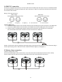
REDMix 3•192 Table of contents 1. Safety instructions ...................................................................................................................................................... 3 2. Fixture exterior view ................................................................................................................................................... 5 3. Installation .................................................................................................................................................................. 5 3.1 Mounting the fixture ............................................................................................................................................ 5 3.2 Changing the lens‐array ........................................................................................................................................ 6 3.3 Connection to the mains ...................................................................................................................................... 7 3.4 DMX 512 connection ............................................................................................................................................ 8 3.5 Master/slave connection ...................................................................................................................................... 8 3.6 Stand‐alone operation .......................................................................................................................................... 9 4. REDMix 3•192 ‐ DMX protocol ................................................................................................................................. 10 5. Control menu map .................................................................................................................................................... 13 6. Fixture menu ............................................................................................................................................................. 15 6.1 Fixture Address ................................................................................................................................................... 16 6.2 Fixture information ............................................................................................................................................. 16 6.3 Personality .......................................................................................................................................................... 17 6.4 Manual mode ...................................................................................................................................................... 18 6. 5 Test sequences ................................................................................................................................................... 19 6.6 Stand‐alone setting ............................................................................................................................................. 19 6.7 Special functions ................................................................................................................................................. 20 7. RDM .......................................................................................................................................................................... 21 8. Error and information messages .............................................................................................................................. 22 9. Technical specifications ............................................................................................................................................ 23 10. Cleaning and maintenance ..................................................................................................................................... 25 10.1 Replacing the main fuse ................................................................................................................................... 25 10.2 Replacing the air filters ..................................................................................................................................... 25 2 REDMix 3•192 FOR YOUR OWN SAFETY, PLEASE READ THIS USER MANUAL CAREFULLY BEFORE POWERING OR INSTALLING YOUR REDMix 3‐192 ! Save it for future reference. This device has left our premises in absolutely perfect condition. In order to maintain this condition and to ensure a safe operation, it is absolutely necessary for the user to follow the safety instructions and warning notes written in this manual. The manufacturer will not accept liability for any resulting damages caused by the non‐observance of this manual or any unauthorized modification to the device. Please consider that damages caused by manual modifications to the device are not subject to warranty. The REDMix 3‐192 was designed for indoor use and it is intended for professional application only. It is not for household use. 1. Safety instructions DANGEROUS VOLTAGE CONSTITUTING A RISK OF ELECTRIC SHOCK IS PRESENT WITHIN THIS UNIT! Make sure that the available voltage is not higher than stated on the rear panel of the fixture. This fixture should be operated only from the type of power source indicated on the marking label. If you are not sure of the type of power supplied, consult your authorized distributor or local power company. Always disconnect the fixture from AC power before cleaning, removing or installing the fuses, or any part. Make sure that the power switch is set to off‐position before you connect the fixture to the mains. The power plug has to be accessible after installing the fixture. Do not overload wall outlets and extension cords as this can result in fire or electric shock. Do not allow anything to rest on the power cord. Do not locate this fixture where the cord may be damaged by persons walking on it. Make sure that the power cord is never crimped or damaged by sharp edges. Check the fixture and the power cord from time to time. Refer servicing to qualified service personnel. This fixture falls under protection class I. Therefore this fixture has to be connected to a mains socket outlet with a protective earthing connection. Do not connect this fixture to a dimmer pack. Do not look straight at the fixture front LEDs during operation. The intense light beam may damage your eyes. If the fixture has been exposed to drastic temperature fluctuation (e.g. after transportation), do not switch it on immediately. The arising condensation water might damage your device. Leave the device switched off until it has reached room temperature. Do not shake the fixture. Avoid brute force when installing or operating the fixture. 3 REDMix 3•192 This fixture was designed for indoor use only, do not expose this unit to rain or use near water. When choosing the installation spot, please make sure that the fixture is not exposed to extreme heat, moisture or dust. Air vents and slots in the fixture´s head and base are provided for ventilation, to ensure reliable operation of the device and to protect it from overheating. The openings should never be covered with cloth or other materials, and never must be blocked. This fixture should not be placed in a built‐in installation unless proper ventilation is provided. Only operate the fixture after having checked that the housing is firmly closed and all screws are tightly fastened. Always use a secondary safety cable when mounting this fixture. Make sure that the area below the installation place is blocked when rigging, derigging or servicing the fixture. Do not block the front objective LEDs with any object when the fixture is under operation. The fixture becomes very hot during operation. Allow the fixture to cool approximately 20 minutes prior to manipulate with it. Operate the fixture only after having familiarized with its functions. Do not permit operation by persons not qualified for operating the fixture. Most damages are the result of unprofessional operation! Please use the original packaging if the fixture is to be transported. Please consider that unauthorized modifications on the fixture are forbidden due to safety reasons! If this device will be operated in any way different to the one described in this manual, the product may suffer damages and the guarantee becomes void. Furthermore, any other operation may lead to dangers like short‐
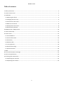
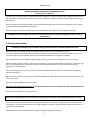
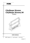
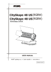
circuit, burns, electric shock, crash etc. 4 REDMix 3•192 2. Fixture exterior view 1. Lens array 2. Mounting bracket 3. Covers 4. Lens‐array lock 5. Lens‐array Security locks Rear panel of the fixture 1. Power switch 2. DMX input/output (5‐pin XLR) 3. LED display 4. Mains input 5. Mains output 6. DMX input/output (3‐pin XLR) 7. Mode button 8. Enter button 9. Up button 10. Down button 3. Installation 3.1 Mounting the fixture Ensure that the structure (truss) to which you are attaching the fixtures is secure. The fixture is supply with mounting bracket which allows truss installation or can serve as a stand for placing directly on the stage. The mounting bracket consists of two parts and it is designed in a way that no tool is needed to adjust desired fixture position. 5 REDMix 3•192 The fixture can be rigged in any orientation on a truss without altering its operation characteristics. The hole in the mounting bracket has a diameter of 10 mm. The installation of the fixture has to be built and constructed in a way that it can hold 10 times the weight for 1 hour without any harming deformation. For overhead use, always install a safety rope that can hold at least 10 times the weight of the fixture. You must only use safety rope with screw‐on carbine. Pull the safety rope through the mounting bracket of the fixture and over the trussing system. 3.2 Changing the lensarray The REDMix 3•192 has a 25° lens‐array module fitted as standard, and is also supplied with a glass holder for frost filters and a grid module. If you wish to change the lens module, follow this procedure: 1. Switch the fixture off. 2. Shift the security lock (1) to the “open “ position (black mark). 3. Press and hold the lens module lock (2) on the side cover of the fixture head and gently lift the module (3) upward at the side where this lock is pressed. 4. Press and hold the lens module lock (2) on the opposite side of the fixture head and gently lift the lens module (3) from its placing and remove it. 5. Fit the new lens module into the fixture head and gently push it downward until the module snaps in. Make sure that the lens module locks (2) are properly locked. 6. Shift the security lock (1) to the “locked” position (red mark) to secure the lens module in the placing. Ensure the security lock is in the “locked” position (RED mark) before starting the fixture operation. It is possible to install a plastic film into the glass holder module in order to get frost light. 1. Uninstall the 25°lens‐array module (1) as described above. 2. Insert the plastic film (2) into the slots under partitions in the glass holder module. 3. Install the glass holder module back to the fixture´s head as described above. 6 REDMix 3•192 The shape (dimensions) of the plastic film depends on its thickness and elasticity. We advice to use 2 shapes of plastic films: Thickness =< 0.5mm Thickness > 0.5 mm Maximum thickness of the film should not exceed 0.8 mm. 3.3 Connection to the mains If it is necessary, install a suitable plug on the power cord, note that the cores in the power cable are colored according to the following table. Core (Eu) Core (US) Connection Plug Terminal Marking Brown Black Live L Light blue White Neutral N Yellow/Green Green Earth This device falls under class one and must be earthed (grounded)! The REDMix 3•192 allows to connect several fixtures in a daisy chain of power cable. Use a 3‐conductor 1.5mm2 patch cord for connecting fixtures each other. Needed types of the cable connectors are stated in the chapter “Technical specifications “ under section. The max. number of connected fixtures depends on the input voltage: 4 fixtures at power supply= 230V (“FuLL” power mode) 2 fixtures at power supply= 120V (“FuLL” power mode) Do not overload the supply line and the connecting leads. Wiring and connection work must be carried out by qualified staff! 7 REDMix 3•192 3.4 DMX 512 connection The fixture is equipped with both 3‐pin and 5‐pin XLR sockets for DMX input and output. Only use a shielded twisted‐
pair cable designed for RS‐485 and 3‐pin/5‐pin XLR‐ connectors in order to connect the controller with the fixture or one fixture with another. Wiring of the XLR connectors: DMX output DMX input XLR mounting sockets (rear view): XLR mounting plugs (rear view): 1 – Shield
2 - Signal (-)
3 - Signal (+)
4 – Not connected
5 – Not connected
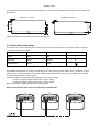
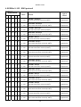
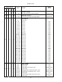
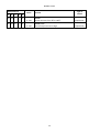
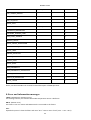
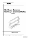
To build a DMX chain 1. Connect the DMX output of the controller directly with the DMX input of the first fixture in the DMX chain. 2. Connect the DMX output of the first fixture in the DMX chain with the DMX input of the next fixture. 3. Always connect the DMX output with the input of the next fixture until all fixtures are connected. Do not overload the link. Max. 32 fixtures may be connected on a DMX link. Caution: Terminate the link by installing a termination plug in the output of the last fixture. The termination plug is a male 3‐pin XLR plug with a 120 Ohm resistor soldered between Signal (–) and Signal (+). 3.5 Master/slave connection To build a master/slave‐chain: Connect the DMX output of the master fixture in the data chain with the DMX input of the first slave. Always connect output with the input of the next slave until all slaves are connected (up to 32 fixtures). 8 REDMix 3•192 Caution: It is necessary to insert the XLR termination plugs (with 120 Ohm) into the input of the master fixture and into the output of the last slave on the data link in order to ensure the proper transmission on the data link. 3.6 Standalone operation The fixtures on a data link are not connected to the controller but can execute pre‐set programs which can be different for every fixture. To set the program to be played, see the "Stand‐alone setting" (menu "St.AL."). "Stand‐alone operation" can be applied to the single fixture or to multiple fixtures operating synchronously. Synchronous operation of multiple fixtures requires that they must be connected on a data link and one of them is set as a master (master mode) and the rest as the slaves (slave mode). To set the fixture as the master or slave, see the "Addressing" (menu "A001"). Only one fixture can be set as the master. The master fixture starts simultaneous program start in the other slave fixtures. All fixtures have a definite, synchronized starting point when playing back their programs. The number of running program is the same in all slaves and depends on the master's choice (menu "St.AL.“). Every fixture runs its program repeatedly, starting the program step No.1 when requested by the master. Example: If the slave fixture has a shorter program length, it will continuously repeat its program until the master fixture finishes its own program and restarts its program running (slave 1‐ prog.step 3 will not be finished). If the slave fixture has a longer program length, it will restart at prog. step 1 before it completes all its prog.steps (slave 2 ‐ prog.step 5 will not be played)‐ see the picture bellow. Note: Disconnect the fixtures from the DMX controller before master/slave operating, otherwise data collisions can occur and the fixtures will not work properly! 9 REDMix 3•192 4. REDMix 3•192 DMX protocol Version 1.1 Mode/Channel Value Function Type of control 1 2 3 4 5 ‐ ‐ 1 1 ‐ 0 ‐ 255 Red LEDs ‐ All Arrays Red LEDs saturation control (0‐100%) proportional ‐ ‐ 2 2 ‐ 0 ‐ 255 Green LEDs ‐ All Arrays Green LEDs saturation control (0‐100%) proportional ‐ ‐ 3 3 ‐ 0 ‐ 255 Blue LEDs ‐ All Arrays Blue LEDs saturation control (0‐100%) proportional ‐ ‐ 4 4 ‐ 0 ‐ 255 White LEDs ‐ All Arrays White LEDs saturation control (0‐100%) proportional 1 1 ‐ ‐ 5 0 ‐ 255 Red LEDs ‐ Array 1 Red LEDs saturation control (0‐100%) proportional 2 2 ‐ ‐ 6 0 ‐ 255 Green LEDs ‐ Array 1 Green LEDs saturation control (0‐100%) proportional 3 3 ‐ ‐ 7 0 ‐ 255 Blue LEDs ‐ Array 1 Blue LEDs saturation control (0‐100%) proportional 4 4 ‐ ‐ 8 0 ‐ 255 White LEDs ‐ Array 1 White LEDs saturation control (0‐100%) proportional 5 5 ‐ ‐ 9 0 ‐ 255 Red LEDs ‐ Array 2 Red LEDs saturation control (0‐100%) proportional 6 6 ‐ ‐ 10 0 ‐ 255 Green LEDs ‐ Array 2 Green LEDs saturation control (0‐100%) proportional 7 7 ‐ ‐ 11 0 ‐ 255 Blue LEDs ‐ Array 2 Blue LEDs saturation control (0‐100%) proportional 8 8 ‐ ‐ 12 0 ‐ 255 White LEDs ‐ Array 2 White LEDs saturation control (0‐100%) proportional 9 9 ‐ ‐ 13 0 ‐ 255 Red LEDs ‐ Array 3 Red LEDs saturation control (0‐100%) proportional 10 10 ‐ ‐ 14 0 ‐ 255 Green LEDs ‐ Array 3 Green LEDs saturation control (0‐100%) proportional 11 11 ‐ ‐ 15 0 ‐ 255 Blue LEDs ‐ Array 3 Blue LEDs saturation control (0‐100%) proportional 12 12 ‐ ‐ 16 0 ‐ 255 White LEDs ‐ Array 3 White LEDs saturation control (0‐100%) proportional 13 13 ‐ ‐ 17 0 ‐ 255 Red LEDs ‐ Array 4 Red LEDs saturation control (0‐100%) proportional 14 14 ‐ ‐ 18 0 ‐ 255 Green LEDs ‐ Array 4 Green LEDs saturation control (0‐100%) proportional 10 REDMix 3•192 Mode/Channel 2 3 4 5 15 15 ‐ ‐ 19 0 ‐ 255 Blue LEDs ‐ Array 4 Blue LEDs saturation control (0‐100%) proportional 16 16 ‐ ‐ 20 0 ‐ 255 White LEDs ‐ Array 4 White LEDs saturation control (0‐100%) proportional Colour Macros No function Macro 1 Macro 2 Macro 3 Macro 4 Macro 5 Macro 6 Macro 7 Macro 8 Macro 9 Macro 10 Macro 11 Macro 12 Macro 13 Macro 14 Macro 15 Macro 16 Macro 17 Macro 18 Macro 19 Macro 20 Macro 21 Macro 22 Macro 23 Macro 24 Macro 25 Macro 26 Macro 27 Macro 28 Macro 29 Macro 30 Macro 31 1 0 ‐ 7 8 ‐ 15 16 ‐ 23 24 ‐ 31 32 ‐ 39 40 ‐ 47 48 ‐ 55 56 ‐ 63 64 ‐ 71 72 ‐ 79 80 ‐ 87 88 ‐ 95 96 ‐ 103 104 ‐ 111 112 ‐ 119 120 ‐127 128 ‐ 135 136 ‐ 143 144 ‐ 151 152 ‐ 159 160 ‐ 167 168 ‐ 175 176 ‐ 183 184 ‐ 191 192 ‐ 199 200 ‐ 207 208 ‐ 215 216 ‐ 223 224 ‐ 231 232 ‐ 239 240 ‐ 247 248 ‐ 255 2 0‐31 32‐63 64‐95 96‐127 128‐143 144‐159 160‐191 192‐223 224‐255 Shutter, Strobe Shutter closed Shutter open Strobe‐effect from slow to fast Shutter open Opening pulses in sequences slow‐‐> fast Closing pulses in sequences fast ‐‐> slow Shutter open Random strobe‐effects from slow to fast Shutter open 1 17 ‐ 5 18 17 6 ‐ ‐ Function Type of control Value step step step step step step step step step step step step step step step step step step step step step step step step step step step step step step step 11 step step proportional step proportional proportional step proportional step REDMix 3•192 Mode/Channel 1 2 Value Function Type of control 3 4 5 19 18 7 ‐ 3 0 ‐ 255 Dimmer Dimmer intensity from 0% to 100% proportional 20 19 8 ‐ 4 0 ‐ 255 Dimmer, fine Fine intensity from low to high proportional 12 REDMix 3•192 5. Control menu map Default settings=Bold print Menu Level 1 Menu Level 2 Menu Level 3 Menu Level 4 Menu Level 5 Menu Level 6 A001 dM.Ad. 001‐512 MA.SL. d.AbL MASt. SLA InFo Poti. FuLL totL rSEt EcO totL rSEt FiLt. AL.PE. 10......300 EL.ti. DM.In. rEd1 0‐255 : F.dim 0‐255 tEMP. Cur.t. boAr.. LEdS Hi.tE. boAr.. LEdS rSEt boAr.. LEdS VErS. IC1 IC2 PErS dM.Pr. Mod.1 Mod.2 Mod.3 Mod.4 Mod.5 13 REDMix 3•192 Menu Level 1 Menu Level 2 Menu Level 3 Menu Level 4 Menu Level 5 Menu Level 6 dISP. d.On On, Off d.Int. 20...100 turn On, Off tEM.U. °C, °F bALA On, Off C.bAL. rEd 0..200..255 GrEn 0..........255 bLuE 0..237..255 Stor LOAd FuLL EcO In.Po. rEd1 0‐255 : F.dim 0‐255 Stor. dFSE MAn.M. PrE.C. rEd1 rE1.1..rE1.3 : dimr dim0...dim.7 Man.C. rEd1 0‐255 : F.dim 0‐255 TESt St.AL. Auto Off tESt PrG.1 : PrG.3 14 REDMix 3•192 Menu Level 1 Menu Level 2 Menu Level 3 Menu Level 4 Menu Level 5 Menu Level 6 PLAY tESt PrG.1 : PrG.3 Edit PrG.1 St.01 rEd1 0‐255 : : : : PrG.3 St.68 S.tim. 0‐25.5 sec CoPY SPEC. rdML rdMH Adj. DMH rEd1 : F.dimr CaL.U. rEd1 : wh4 Stor. uPd.M. 6. Fixture menu The control panel menu allows to set the fixture according to your needs, obtain information on its operation, test its various parts and lastly program it, if it has to be used in a Stand‐alone mode. The four control buttons on the front have the following functions: MODE button‐leaves menu without saving changes. ENTER button‐ enters menu, confirms adjusted values and leaves menu. UP and DOWN buttons ‐ move between menu items on the same level, sets values. After switching the fixture on, the fixture display shows the current DMX address: Use the UP/DOWN buttons to scroll through the various menu items. To select desired item, press the ENTER. 15 REDMix 3•192 6.1 Fixture Address Use this menu to set the DMX address of the fixture or set the fixture as a Master (Slave). dM.Ad. ‐‐‐ DMX addressing. Select this submenu to set a DMX start address. To set a DMX address. 1. Use the UP/DOWN buttons to find “ A001“ menu. 2. Press the ENTER button. 3. Use the UP/DOWN buttons to select desired start address. 4. Press the ENTER button to confirm the choice. MA.SL. ‐‐‐ Master/slave addressing. Select this submenu to set the fixture as a master or slave. Option "d.AbL" deactivates master/slave setting. To set a fixture as a master or slave. 1. Use the UP/DOWN buttons to find “A001“ menu. 2. Press the ENTER button. 3. Use the UP/DOWN buttons to select “ MA.SL.“ item. 4. Press the ENTER button. 5. Use the UP/DOWN buttons to select either master (MASt) or slave (SLA) 6. Press the ENTER button to confirm the choice. Note: After switching on, the REDMix 3•192 will automatically detect whether DMX 512 data is received or not. If there is no data received at the DMX input, the display will start to flash “A001” with actually set address. 6.2 Fixture information Use this menu to read useful information about the fixture status. To display desired information. 1. Use the UP/DOWN buttons to find the “ InFo“ menu. 2. Press the ENTER button. 3. Use the UP/DOWN buttons to select the required menu item. 4. Press the ENTER button to confirm the choice. Po.ti. ‐‐‐ Power On Time. Use the menu item to read the number of operation hours for each LEDs operating mode. FuLL‐‐‐Max light output from the fixture. totL ‐ the function shows the total number of the operation hours in the “FuLL” mode since the REDMix 3•192 has been fabricated. rESEt ‐ the function shows the number of the operation hours that the REDMix 3•192 has been powered on in the “FuLL” mode since the counter was last reset. In order to reset this counter to 0 you have to press and hold the UP and DOWN buttons and at the same time press the ENTER button. EcO‐‐‐Economical mode. totL ‐ the function shows the total number of the operation hours in the “EcO” mode since the REDMix 3•192 has been fabricated. rESEt ‐ the function shows the number of the operation hours that the REDMix 3•192 has been powered on in the “EcO” mode since the counter was last reset. In order to reset this counter to 0 you have to press and hold the UP and DOWN buttons and at the same time press the ENTER button. 16 REDMix 3•192 FiLt ‐‐‐ Filters. Regular cleaning of the air filters is very important for the fixture´s life and performance. Cumulation of dust, dirt and fog fluid residues reduces the fixture´s light output and cooling ability. The two items of this menu help you to keep cleaning period of the air filters. AL.PE. ‐‐‐ Set alert period ‐ cleaning schedule for the fixture depends on the operating environment. It is therefore impossible to specify accurate cleaning interval. This function allows you to change the cleaning interval of the air filters. This “alert“ value is 50 hours and it is set as default. Inspect the fixture within its 50 hours of operation to see whether cleaning is necessary. If cleaning is required, clean all air filters and change the value in this menu on acceptable level. Min. level of alert period is 10 hours, max. is 300 hours. EL.ti. ‐‐‐Elapsed time ‐ the option allows you to read the time which remains to cleaning air filters. The time period is set in the menu mentioned above. Expired time period is signalized by the message ”FiLt” on display. Clean the filters and reset this menu item (pressing and hold the UP and DOWN buttons and at the same time press the ENTER button). DM.In.‐‐‐DMX values. Select this function to read DMX values of each channel received by the fixture. tEMP ‐‐‐ Fixture Temperatures. Select this menu to read the temperatures of the fixture: Cur.t. ‐‐‐ the current temperature of the fixture inside. Hi.tE. ‐ the menu item shows the max. temperatures of the fixture inside since the REDMix 3•192 has been fabricated. rSEt ‐‐‐ the menu item shows the maximum temperatures of the fixture inside since the counter was last reset. In order to reset this counter to 0 you have to press and hold the UP and DOWN buttons and at the same time press the ENTER button. Note: The ambient temperature should not exceed 40°C. Measuring points: LEdS.‐‐‐ the temperature of the LEDs module. boAr. ‐‐‐ the temperature on the PCB in the fixture head. The temperatures can be displayed in either °C or °F units ‐ see option “tEM.U“ in the menu “Pers“. VErS. ‐‐‐Software Versions. Select this function to read the software versions of the fixture processors: IC1 ‐‐‐ the processor controls LEDs module IC2 ‐‐‐ EEprom 6.3 Personality Use this menu to modify the REDMix 3•192 operating behaviour. DM.Pr. ‐‐‐ DMX preset. Select this menu item to set a desired DMX mode. Please refer to the chapter "DMX protocol" for detail description of each DMX mode. DiSP. ‐‐‐ Display adjusting. This function allows you to change the display settings. d.On ‐‐‐ this function allows you to keep the display on or to turn off automatically 2 minutes after last pressing any button on the control panel. d.Int. ‐‐‐ select this function to adjust the display intensity (20‐min.,100‐max.). turn ‐‐‐ select this function to turn the display by 180°. tEM.U. ‐‐‐ Temperature Unit. Use this menu in order to display the fixture temperatures in desired units: °C or °F. bALA ‐‐‐ Balance Use this menu item to enable (On) or disable (Off) the white balance which is set in the “White colour balance“ menu below. I f this function is set off, the REDMix 3•192 will use maximum values (255) of saturation for red, green and blue colour. This function has to be set on before adjusting a white balance. 17 REDMix 3•192 C.bAL. ‐‐‐ White Colour Balance. The menu gives access to the setting of the white balance. To set white colour balance. 1. Use a DMX controller or the “ Man.C.“ menu to set all LEDs on max. saturation. 2. Use the UP/DOWN buttons to find the “ Pers.“ menu. 3. Press the ENTER button. 4. Use the UP/DOWN buttons to select the “C.bAL“menu. 5. Press the ENTER button and the “rEd“ item will appear on the display. 6. Press the ENTER button and use the UP/DOWN buttons to set new max. value for the red LEDs. 7. Press the ENTER button to confirm the choice. 8. Use the UP/DOWN buttons to select next colour, the “GrEn“. 9. Repeat steps 6‐7 for this channel. 10. Use the UP/DOWN buttons to select the last colour, the „bLuE“ and repeat steps 6‐7 for this colour. LoAd ‐‐‐ Load of LEDs. The menu allows to choose 2 different operating modes for fixture´s LEDs. FuLL ‐‐‐ Maximum light output. Note: in this mode, the total lumen maintenance is 70% at 10,000 hours. EcO. ‐‐‐ The light output is decreased by 20%. The total lumen maintenance is 70% at 60,000 hours. In.Po. ‐‐‐ Init effect positions. Use this function to set all effects to the desired positions to which they will move after switching the fixture on (if DMX is not being received). dF.SE. ‐‐‐ Default Settings .The menu item sets all fixture parameters to the default (factory) values. 6.4 Manual mode Use this menu for control the fixture without connected DMX console. PrE.C. ‐‐‐ Preset effects control. Select this menu to call up preset positions of the channel effects. Man.C. ‐‐‐ Manual effect control. Select this menu to control all channels via buttons of the control board. To control fixture channels. 1. Use the UP/DOWN buttons to find “ Man.C“ menu. 2. Press the ENTER button. 3. Use the UP/DOWN buttons to select desired effect (channel). List of control channels: “rEd1” ‐ “rEd4” ‐ red LEDs saturations “GrE1“ ‐ “GrE4“ ‐ green LEDs saturations “bLu1“ ‐ “bLu4“ ‐ blue LEDs saturations “Whi1“ ‐ “Whi4“ white LEDs saturations “MACr“ ‐ colour macros “Stro.“ ‐ a strobe, shutter “dimr“ ‐ a dimmer 4. Press the ENTER button and use the UP/DOWN buttons to set value , press the ENTER button to confirm it. 18 REDMix 3•192 6. 5 Test sequences Use this menu to run demo‐test sequences without an external controller, which will show you some possibilities of using the REDMix 3•192. 6.6 Standalone setting The fixtures on a data link are not connected to the controller but can execute pre‐set programs which can be different for every fixture. “Stand‐alone operation” can be applied to the single fixture or to multiple fixtures operating synchronously. Synchronous operation of multiple fixtures requires that they must be connected on a data link and one of them is set as a master (“MASt“) and the rest as the slaves (“SLA“). Up to 32 fixtures can be connected in a master/slave chain. Only one fixture can be set as the master. Note: Disconnect the fixtures from the DMX controller before master/slave operating, otherwise data collisions can occur and the fixtures will not work properly. See the chapters “Stand‐alone operation“ and “ Master/slave connection“. Auto. ‐‐‐ Automatic playback. This function allows you to select the program which will be played after switching the fixture on. Selected program will be played continuously in a loop. 1. Use the UP/DOWN buttons to find “ St.AL.“ menu. 2. Press the ENTER button. 3. Use the UP/DOWN buttons to select “ Auto“ item. 4. Press the ENTER button. 5. Use the UP/DOWN buttons to select desired program. 6. Press the ENTER button to confirm the choice. PLAY ‐‐‐ Playing program. By enter to this menu a complete overview of all programs is offered, from which the program to be run can be selected. 1. Use the UP/DOWN buttons to find “ St.AL.“ menu. 2. Press the ENTER button. 3. Use the UP/DOWN buttons to select desired program. 4. Press the ENTER button. The selected program runs in a loop. Edit ‐‐‐ Editing a program. The fixture offers 3 freely editable programs (EPG.1‐EPG.3) each up to 68 steps. Every program step includes a fade time‐the time taken by the step´s channel status to reach the desired level and a step time‐the total time occupied by the step in the program. E.g. If “F.tim.“=5 second and “S.tim.“=20 second, effects will go to the desired position during 5 seconds and after that they will stay in this position for 15 seconds before going to the next prog. step 1. 1. Use the UP/DOWN buttons to find “ St.AL.“ menu and press the ENTER button. 2. Use the UP/DOWN buttons to select “Edit“ menu and press the ENTER button. 3. Use the UP/DOWN buttons to select a program you want to edit (PrG.1‐PrG.3 and press ENTER button. 4. Use the UP/DOWN buttons to select a desired program step ("St.01" ‐ "St.68") and press ENTER button. 5. Use the UP/DOWN buttons to select a channel you want to edit and press the ENTER button. List of editable items: “P.End” ‐ a total number of the program steps (value 1‐68). This value should be set before start Programming (e.g. if you want to create program with 10 steps, set P.End=10). “rEd1” ‐ “rEd4” – a red LEDs saturation (0‐255) “GrE1“ ‐ “GrE4“ –a green LEDs saturation (0‐255) “bLu1“ ‐ “bLu4“ – a blue LEDs saturation (0‐255) “Whi1“ ‐ “Whi4“ – a white LEDs saturation (0‐255) 19 REDMix 3•192 “MACr“ ‐ colour macros (0‐255) “Stro.“ ‐ a strobe, shutter (0‐255) “dimr“ ‐ a dimmer (0‐255) “F.tim.“ ‐ a fade time, (0‐25.5) seconds “S.tim.“ ‐ step time, value (0‐25.5) seconds “COPY“. – this item duplicates the current prog. step to the next prog. step. The item “P.End” is increased automatically. 6. Use the UP/DOWN buttons to set a DMX value of the channel and then press the ENTER button. 7. Use the UP/DOWN buttons to select next channel and press the ENTER button. 8. After having set all channels in the current program step, press the MODE button to go by one menu level back and select another program step. 6.7 Special functions rdML ‐‐‐ Code.This menu item shows the first part of the RDM identification code. rdMH ‐‐‐ Code. This menu item shows the second part of the RDM identification code. AdJ ‐‐‐ Effect Adjustment. The menu allows calibration of each LEDs array. dMH ‐‐‐ DMX Values. The menu item enables to control all LEDs before calibrating each LEDs array. CAL.U ‐‐‐ Calibrating unit. The menu serves for fine current calibration of LEDs during fixture burn‐in at a factory. Each LED array can be calibrated separately. Users should not change the setting. uPd.M. ‐‐‐ Updating mode. The menu item allows you to update software in the fixture via either serial or USB port of PC. The following are required in order to update software: ‐ PC running Windows 95/98/2000/XP or Linux ‐ DMX Software Uploader ‐ Flash cable RS232/DMX No.13050624 (if you want to use a serial port of PC) ‐ DreamBox (if you want to use an USB port of PC) Note1: Software update should execute a qualified person. If you lack qualification, do not attempt the update yourself and ask for help your ROBE distributor. Note 2: DMX address, programs 1‐3 and all items in the menu "PErS" will be set to their default values. To update software in the fixture: I. Installation of the DMX Software Uploader. 1. DMX Software Uploader program is available from the ROBE web site at WWW.robe.cz. 2. Make a new directory ( e.g. Robe_Uploader) on your hard disk and download the software to it. 3. Unpack the program from the archive. (If the Robe fixture is produced in both magnetic and electronic ballast version, name of DMX Software Uploader is the same for both versions). II.Fixture software updating. 1. Determine which of your ports is available on your PC and connect it: ‐ with the DMX input of the fixture if you using the flash cable RS232/DMX ‐ with the DMX input of the DreamBox if you using the USB cable. Disconnect the fixture from the other fixtures in a DMX chain. Turn both the computer and the fixture on. Make sure the lamp is switched off (only if the fixture involves a lamp). 2. Switch the fixture to the updating mode: 1 Use the UP/DOWN buttons to find “SPEC.“ menu. 2 Press the ENTER button. 3 Use the UP/DOWN buttons to select “ uPd.M.“ item. 20 REDMix 3•192 4 Press the ENTER button 5 Use the UP/DOWN buttons to select “ yES“ option 6 Press the ENTER button Note: If you do not want to continue in software update, you have to switch off and on the fixture to escape from this menu. 3. We recommend to cancel all running programs before start the Software Uploader. 4. Run the Software Uploader program. Select desired COM and then click on the Connect button. Select COM if the seriál port is used. Select DreamBox1 if the USB port is used. If the connection is OK, click on the Start Uploading button to start uploading. It will take several minutes to perform software update. If the option "Incremental Update" is not checked, all processors will be updated (including processors with the same software version). If you wish to update only later versions of processors, check the Incremental Update box. Avoid interrupting the process. Update status is being displayed in the Info Box window. When the update is finished, the line with the text “The fixture is successfully updated‘will appear in this window and the fixture will reset with the new software. Note: In the case of an interruption of the upload process (e.g. power cut), the fixture keeps the updating mode and you have to repeat the software update again. For example: The fixture was switched off before finishing software upload. After switching again the fixture on, the fixture is still in the updating mode and the display is dark. Restart the Software Uploader program and repeat software update from your PC. 7. RDM This fixture is ready for RDM operation.RDM (Remote Device Management) is a bi‐directional communications protocol for use in DMX512 control systems, it is the new open standard for DMX512 device configuration and status monitoring. The RDM protocol allows data packets to be inserted into a DMX512 data stream without adversely affecting existing non‐RDM equipment. By using a special „Start Code,“ and by complying with the timing specifications for DMX512, the RDM protocol allows a console or dedicated RDM controller to send commands to and receive messages from specific moving lights. RDM allows explicit commands to be sent to a device and responses to be received from it. The list of commands for REDMix 3•192 is the following. 21 REDMix 3•192 Parameter ID Discovery command
SET command
GET command DISC_UNIQUE_BRANCH * DISC_MUTE * DISC_UN_MUTE * DEVICE_INFO * Parameter ID Discovery command
SET command
GET command SUPPORTED_PARAMETERS * SOFTWARE_VERSION_LABEL * DMX_START_ADDRESS * * IDENTIFY_DEVICE * * DEVICE_MODEL_DESCRIPTION * MANUFACTURER_LABEL * DEVICE_LABEL * * SENSOR_DEFINITION * SENSOR_VALUE * DISPLAY_LEVEL * * DEVICE_RESET * DMX_PERSONALITY * * DMX_PERSONALITY_DESCRIPTION * STATUS_MESSAGES * STATUS_ID_DESCRIPTION * DEVICE_HOURS * Please, see the DreamBox user manual for detail description of RDM operation. 8. Error and information messages t.M.Er.(Temperature measuring error) The message informs you that the LED module temperature sensor is defective. MA.Er. (Master error) The fixture is set as a master and DMX console is connected to the fixture. Fi.Er. Expired alert period. Clean the filters and reset “EL.ti.” item in menu “InFO” (InFo ‐‐> FiLt‐‐>EL.ti). 22 REDMix 3•192 9. Technical specifications Power supply • Electronic auto‐ranging • Input voltage: 100 ‐ 250V AC, 50‐60 Hz • Fuse: T8 A • Max. power consumption: 700W ( Full mode) 400 W (Eco mode) • Daisy chain of power cable for up to: 4 fixtures (at power supply= 230V) 2 fixtures (at power supply= 120V) Optic & Effects • Light source: 192 Luxeon Rebel LEDs (RGBW) • Optical system: 12° without lens‐array and 25° lens‐array (standard); 45° or 15°x45° lens‐array (optional) • Fitting of additional frost film filters • Lumen Maintenance: 70% @ 60,000 hours (Eco mode) • Lumen Maintenance: 70% @ 10,000 hours (Full mode) • RGBW colour mixing • Built‐in colour macros • Adjustable strobe sequences • White colour balance adjusting Electronics • Control panel: 4‐digit LED display and four control buttons • Control: USITT DMX 512 (RDM support) • DMX protocol modes: 5 (4, 8, 19 or 20 control channels) • Control options: DMX, Auto‐trigger • Operations modes: DMX, Stand‐alone, Master/Slave • Manual control of all effects via control panel Strobe • Strobe effect with variable speed (max. 20 flashes per second) • Pre‐programmed random strobe pulse‐effects Dimmer • Smooth 16‐bit dimming from 0 ‐ 100 % Connectors • DMX data in/out: Locking 3‐pin and 5‐pin XLR • AC power input: Chassis connector Neutrik PowerCon, A‐type, NAC3MPA • AC power output: Chassis connector Neutrik PowerCon, B‐type, NAC3MPB Cable plugs: Cable connector Neutrik PowerCon, A‐type, NAC3FCA , for power‐in, (installed on the power cord) Cable connector Neutrik PowerCon, B‐type, NAC3FCB, for power‐ out, (it is not a part of delivery) Rigging • Mounting bracket Temperatures • Maximum ambient temperature: 40° C • Maximum housing temperature: 70° C 23 REDMix 3•192 Dimensions (mm) Weight • 10 kg Included items • 1 x REDMix 3•192 • 1 x Lens module 25° (No. 99012301) – installed in the fixture • 1 x glass holder for frost filter (No. 10980055) • 1 x grid module (No. 17040456) • 1 x User manual Optional accessories • Lens module 45° (No. 10980053) • Lens module 15°x45° (No. 10980054) • Flash cable RS232/DMX (No. 13050624) Note: By reason of the fast-moving development of LED technology, later products may have better light parameters
than previous products.
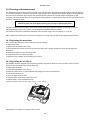
24 REDMix 3•192 10. Cleaning and maintenance It is absolutely essential that the fixture is kept clean and that dust, dirt and smoke‐fluid residues must not build up on or within the fixture. Otherwise, the fixture‘s light‐output will be significantly reduced. Regular cleaning will not only ensure the maximum light‐output, but will also allow the fixture to function reliably throughout its life. A soft lint‐free cloth moistened with any good glass cleaning fluid is recommended, under no circumstances should alcohol or solvents be used! DANGER ! Disconnect from the mains before starting any cleaning or maintenance work The glass holder and lens modules will require weekly cleaning as smoke‐fluid tends to building up residues, reducing the light‐output very quickly. The cooling fans should be cleaned monthly. The interior of the fixture should be cleaned at least annually using a vacuum‐cleaner or an air‐jet. More complicated maintenance and service operations are only to be carried out by authorized distributors. 10.1 Replacing the main fuse Only replace the fuse by the one of the same type and rating. To replace the fuse: 1. Disconnect the fixture from mains. 2. Unscrew the fuse holder on the rear panel of the base with a fitting screwdriver from the housing (anti clockwise). 3. Remove the old fuse from the fuse holder. 4. Install the new fuse in the fuse holder. 5. Replace the fuse holder in the housing and screw it. 10.2 Replacing the air filters The REDMix 3•192 is supplied with 2 air filters placed in the fixture head. Clean the air filters with a vacuum cleaner or you can wash them and put back dry. To replace the air filters: 1. Disconnect the fixture from mains. 2. Raise up a filter cover (1) (fastened with two magnets) on the top head cover. 3. Pull out the air filter (2). 4. Clean or replace the air filter. 5. Snap the filter cover back to the head cover. 6. Repeat steps 2‐5 for the bottom cover. 7. Reset the item “EL.ti.“ in the „InFo“ (InFo ‐‐> FiLt‐‐>EL.ti). Specifications are subject to change without notice. 25