1
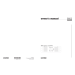
owner’s manual
X-Rack
XRM -
rack mount mixers
12 Output Monitor Mixer
Important precautions
1
Save the carton and packing materials!
Should you ever need to ship the unit,
use only the original factory packing.
For replacement packaging, call Crest Audio’s
Customer Service Department directly.
2
3
Read all documentation before
operating your equipment. Retain all
documentation for future reference.
Follow all instructions printed on
unit chassis for proper operation.
Service Information
Do not open unit!
Opening the unit will expose you to
potentially dangerous voltages.There are
no user serviceable parts inside.
Equipment should be serviced by
qualified service personnel when:
A. The equipment has been exposed to rain.
B. The equipment does not appear to oper-
ate normally,or exhibits a marked change in
performance.
C. The equipment has been dropped, or the
enclosure damaged.
4
Do not use the unit if the electrical
power cord is frayed or broken.
The power supply cord should be routed so that it is not likely to be walked on
or pinched by items placed upon or
against it.
5
Always operate the unit with the
AC ground wire connected to the
electrical system ground. Precautions
should be taken so that the means of
grounding of a piece of equipment is not
defeated.
6
Damage caused by connection to
improper AC voltage is not covered
by any warranty.
7
Do not spill water or other liquids
into or on the unit, or operate the
unit while standing in liquid.
8
The power cord of equipment
should be unplugged from the outlet when left unused for a long period of time.
To obtain service:
contact your nearest Crest Audio
Service Center, Distributor, Dealer,
or Crest Audio at 201.475.4600 USA
or visit www.crestaudio.com for additional information.
email
[email protected]
XRM owner’s manual
This symbol is used to alert
the operator to follow important
procedures and precautions
detailed in documentation.
This symbol is used to warn operators that uninsulated “dangerous
voltages” are present within the
equipment enclosure that may
pose a risk of electrical shock.
table of contents
Introduction
Thank you and congratulations on your purchase of your new
Crest Audio X-Rack mixer.We’re confident that you will enjoy
many years of trouble-free service from it.You will quickly find
that it fits into a wide variety of mixing applications with ease.
Due to well thought out sets of features, coupled with intelligent circuit design and the highest standards in construction &
workmanship, all Crest Audio console products excel above and
beyond the competitor’s products, in every area.
This owner’s manual covers the XRM X-Rack mixer.The XRM
has 12 Mono inputs and 4 Stereo inputs, adding up to a total of
20 microphone inputs. Each input can feed any of 12 outputs.
Please read this manual thoroughly and keep it handy for future
reference. If you have any operating concerns that are not covered in this manual, or have application questions of any type,
don’t hesitate to contact Crest Audio directly either by phone,
fax, or email. Here is our technical support contact information:
Phone: (201) 475-4600
Fax: (201) 475-4677
Email: [email protected]
Mono Input channels
p. 7
Front panel controls and rear panel connections
Stereo Input channels
p.19
Front panel controls and rear panel connections
Master section
P .29
Solo and Monitoring System, Output Masters.
Front panel controls and rear panel connectors.
Specifications
P. 41
1
2
3
4
p.4
RIGHT
26dB
PAD
XRM BLK DIA-REV1.0 - 5/20/02
AC IN
100-240V
50 / 60 Hz
80W
X-RACK REAR PANEL:
AC INLET & SWITCH
POWER
ON
SOLO-LINK CONNECTORS.
USE 5-PIN DIN CABLE FROM
SLAVE CONSOLE OUT
TO MASTER CONSOLE IN
IN
FADER
P
SIG
LED
G
OUT
SOLO-LINK:
HI MID
400 - 8 KHZ
FREQ LEVEL
HI MID
400 - 8 KHZ
HI MID
400 - 8 KHZ
POST
FADER
L&R
RIGHT
LEFT
PRE
EQ
PRE
FADER
PRE
EQ
PRE
FADER
HF
12 KHZ
HF
12 KHZ
LEVEL
BICOLOR GROUND COMP BALANCED
DRIVER
DRIVER
LED
GC
PRE-AMP
OUT
L&R
SOLO
TRIGGER
FOUR BAND EQ - RIGHT
LOW MID
80 - 2 KHZ
FOUR BAND EQ - LEFT
LOW MID
80 - 2 KHZ
PRE
FADER
L&R
LF
80 HZ
LF
80 HZ
FREQ LEVEL
4 STEREO INPUTS AVAILABLE
AMP
GAIN
INTERNALLY FUSED AND
SHORT-CIRCUIT PROTECTED
POLY
FUSES
AUX DC
GROUND
+12V
ANALOG
GROUND
+48V
-17V
+17V
SHORT-CIRCUIT
PROTECTION
TO POWER
DISTRIBUTION
RIBBONS
DC OUTPUT
BNC CONNECTOR
FOR 12VOLT LAMP
( ON FRONT PANEL )
PRE
FADER
RIGHT
FITTED
SOLDER
LINK
BLOB
USER OPTIONS
PRE-SOURCE
BUFFERS
LEFT
PRE
FADER
RIGHT
+10
+10
LEFT
FADER
AMPS
FET
SWITCH
SUM
POST
FADER
ELECT
SWITCH
MIX 1-4
PRE
PFL
RCA
JACK
SOLO DC
LEV / LEV
__
LEV / PAN
SWITCHING
LEV__
/ LEV
LEV / PAN
SWITCHING
LEV__
/ LEV
LEV / PAN
SWITCHING
LEV / LEV
__
LEV / PAN
SWITCHING
LEV__
/ LEV
LEV / PAN
SWITCHING
LEV__
/ LEV
LEV / PAN
SWITCHING
LEV__
/ LEV
LEV / PAN
SWITCHING
LEV__
/ LEV
LEV / PAN
SWITCHING
LEV__
/ LEV
LEV / PAN
SWITCHING
SOLO DC
SOLO RIGHT
SOLO LEFT
LEV__
/ LEV
LEV / PAN
SWITCHING
OBE
FRANK
LEGENDS
XLR
JACK
LEV__
/ LEV
LEV / PAN
SWITCHING
MIX SENDS 11 & 12
MIX SENDS 9 & 10
MIX SENDS 7 & 8
MIX SENDS 5 & 6
MIX SENDS 3 & 4
MIX SENDS 1 & 2
PFL
SOLO LEFT
SOLO RIGHT
LEV / LEV
__
LEV / PAN
SWITCHING
MIX SENDS 11 & 12
MIX SENDS 9 & 10
MIX SENDS 7 & 8
MIX SENDS 5 & 6
MIX SENDS 3 & 4
MIX SENDS 1 & 2
1/4” TRS
JACK
TO
PEAK CIRCUIT
MIX 1-4
PRE
TO
PEAK
CIRCUIT
STANDARD OUTPUT LEVEL IS +4 dBu AT 0 VU
PIN 2 HOT ON ALL BALANCED INPUTS AND OUTPUTS (XLR JACKS)
FOR UNBALANCED OPERATION:
TIE PIN 3 TO PIN 1, USE PIN 2 FOR OUTPUT, PIN 1 FOR GND
“Ø” SYMBOL INDICATES POLARITY REVERSE
PANEL
SWITCH
NO
MUTE
PRE
SOURCE
MUTE ?
YES
CHAN
LEVEL
PRE
FADER
PRE-SOURCE
BUFFER
NO
YES
+10
FADER AMP
MUTE
PRE
SOURCE
MUTE ?
CHAN
FADER
PRE-SOURCE
SELECT
EQ ON
PRE
EQ
EQ ON
PRE-SOURCE
SELECT
PRE
INSERT
HF
12 KHZ
LEVEL
XRM STEREO INPUT MODULE
PRE
FADER
POST
FADER
SOLO
TRIGGER
FOUR BAND EQ
LOW MID
80 - 2 KHZ
LEVEL FREQ LEVEL
G
CHASSIS
GROUND
TIES SOLO AUDIO AND
CONTROL BETWEEN
CONSOLES. SLAVE SOLOS
SHOW UP ON MASTER
CONSOLE.
UNIVERSAL INPUT-VOLTAGE
SWITCHING POWER SUPPLY
SAFETY
GROUND
TO CHASSIS
INPUT
SIGNAL
LED
PEAK R
(PFL)
PAD
PRE
EQ
SIG
PEAK R
(PFL)
INPUT
SIGNAL
LED
LF
80 HZ
LEVEL FREQ LEVEL
12 MONO INPUTS AVAILABLE
XRM MONO INPUT MODULE
ALL SWITCHES SHOWN IN THE UP (DESELECTED) POSITION
AMP(LIFIER) GAIN SHOWN IN DB WHEN NEEDED
WHEN SHOWN: 1/4” TRS SWITCHING JACKS HAVE NORMALLY CLOSED CONTACTS
USER OPTIONS IMPLEMENTED WITH REMOVABLE LINKS AND SOLDER BLOBS
DEFAULT OPTION POSITION SHOWN UNDERLINED
Use 5-Pin DIN cable to
interconnect two Consoles
SOLO
LINK
SUM
MONO
HPF
HPF
70Hz
-18dB/Oct
ROTARY
POT
INPUT
PREAMP
GAIN
15 - 60 dB
INPUT
PREAMP
GAIN
10 - 70 dB
LINE
(MIC PAD)
LINE
(MIC PAD)
LEFT
26dB
PAD
26dB
PAD
XRM BLOCK DIAGRAM
REAR PANEL
BAL LINE IN
SPLIT
OUT
BAL XLR
IN
PIN 1 LIFT
SPLIT
OUT
BAL XLR
IN
+48V ON
REAR PANEL
INSERT
SEND / RTN
BAL LINE IN
PIN 1 LIFT
SPLIT
OUT
BAL XLR
IN
+48V ON
M12
M11
M10
M9
M8
M7
M6
M5
M4
M3
M2
M1
EVEN
MIX BUSES
2
4
6
8
10
12
1
3
5
7
9
11
ODD
MIX BUSES
SOLO DC
SOLO RIGHT
SOLO LEFT
SOLO
CONTROL
LOGIC
SOLO
MIX AMPS
SOLO
FEED
L-R
L
R
COMMON
INPUT
LEVEL
FOLLOW SOLO
LED
METERS
SOLO
ON
HPF
40Hz
-18dB/Oct
M12
EVEN
MIX AMP
SOLO
LOGIC
&
SWITCH
LO-CUT
ON
HPF
HPF
40Hz
-18dB/Oct
HPF
SOLO DC
SOLO RIGHT
SOLO LEFT
STEREO PAIR
CTRL TO
INPUT SENDS
STEREO
PAIR
AFFECTS BOTH
ODD & EVEN
ODD
MIX AMP
M11
M10
M9
M8
M7
M6
M5
M4
M3
M2
M1
MAIN
RIBBON
CABLE
40 WAY
+9
6
3
0
-3
6
9
12
15
18
21
24
L
SIG/PK
LED
SIG
SIG
G
G
60MM
EVEN
FADER
PRE
FADER
60MM
ODD
FADER
PRE
FADER
HEADPHONE
AMP
COMMON INPUT CIRCUITRY
MONITOR / HP
LEVEL
SPEAKER
ON
SOLO AND MONITOR CIRCUITS
PWR
ON
R
SIG/PK
LED
PEAK R
(AFL)
PEAK R
(AFL)
AFL-EVEN
AFL-ODD
XRM MIX PAIR
1 OF 6 PAIRS SHOWN
HEADPHONE
JACK
+10
+10
POST
FADER
POST
FADER
COMMON
INPUT - R
COMMON
INPUT - L
MONITOR
OUT - R
MONITOR
OUT - L
EVEN MIX
BAL OUT
MIX INSERT
SEND / RTN
EVEN MIX
BUS IN
ODD MIX
BAL OUT
MIX INSERT
SEND / RTN
ODD MIX
BUS IN
XRM block diagram
XRM owner’s manual
how to use this manual
format
This manual uses a format that is intended to be easy to read, yet technical for those
who need to know all the details. For feature descriptions, this is done by devoting the
left side of each page to 1) an overall module picture, 2) a block diagram, and 3) a control closeup.These images all pertain to the features and control descriptions on the
right side of the page.The intention is to make the manual easy to read while including
all the technical details needed for getting the most out of the X-Rack - a compact, flexible, feature-rich addition to Crest Audio's growing line of audio mixing console products.
conventions
Control Icons
This manual uses symbols to illustrate what the control descriptions are referring to.This
makes it possible to avoid redundant wording and makes the control descriptions clear.
Switch in the UP, non-activated position
Switch in DOWN, activated position
Switch that illuminates when in the DOWN position
Momentary switch that illuminates when activated
LED that is on, indicating that it's associated feature is activated
LED
Potentiometer
T= IN +
R= IN –
S= GND
Standard 1/4" TRS jack (used for line level inputs)
T= Send
R= Return
S= GND
1/4" TRS jack with normal switching (used on inserts)
Female XLR input jack
Male XLR output jack
p.5
1 Mono input channel
XRM owner’s manual
Module
Controls
LINE INPUT
( MIC PAD )
40 GAIN
20
40 GAIN
50
10
20
70
LO CUT
0
–
50
+ HF
8
8
15
2K
10
15
5K
600
400
LO CUT
6
8K
0
–
70
3K
1K
HM
+
8
8
15
500
500
300
0
F
15
500
500
500
500
500
500
500
500
500
500
500
500
HF
500
500
1K
100
2K
0
–
LM
+
8
8
15
15
0
–
+ LF
8
8
15
Block diagram
15
EQ
ON
1
MIX SENDS
+48V ON
PRE
–
10
20
30
40
S
T
R
•
6
–
0 2
+
3
•
6
10
20
30
40
–
10
20
30
40
•
•
6
–
0 6
+
3
20
•
•
•
6
–
0 10
+
3
•
6
10
–
10
20
BAL LINE IN
•
6
MUTE
INSERT
SEND / RTN
1
CHAN
LEVEL
–
0
+
5
10
20
30
40
•
10
PK
SIG
REAR PANEL
PFL
p.6
PEAK
(PFL)
SIG
6
–
0 12
+
3
10
IN
SIG
L
0 11
+
3 S
T
R
•
20
30
40
INPUT
PREAMP
26dB
PAD
0 9
+
3
S
T
R
20
30
40
PIN 1 LIFT
6
–
10
20
30
40
SPLIT
OUT
6
–
0 8
+
3
20
HPF
70Hz
-18dB/Oct
HPF
0 7
+
3
S
T
R
•
10
30
40
GAIN
10 - 70 dB
6
–
10
20
30
40
500
0 5
+
3
S
T
R
•
10
30
40
LINE
(MIC PAD)
6
–
10
20
30
40
500
0 3
+
3
6
–
0 4
+
3
10
30
40
BAL XLR
IN
S
T
R
20
30
40
0 1
+
3
500
Mono Input channel
1
Front panel features
Line Input (Mic Pad)
With this switch in the UP position, the input preamp circuit is set up to accept a mic-level
signal. This signal is brought in via the XLR mic-input connector located on the rear panel.The
1/4" TRS input jack is ignored.
When the switch is depressed, a Pad is inserted into the signal path and the input preamp
circuit is set up to accept a line-level signal from either the XLR mic-input connector or the 1/4"
TRS input jack, both located on the rear panel.The XLR signal is normal'd to the 1/4” TRS jack. If
nothing is plugged into the TRS jack, the XLR signal is fed to the preamp when the LINE switch is
pressed. Since the TRS signal is always padded down by 26dB, this feature allows the LINE switch
to act as a PAD switch for bringing a very hot microphone signals down to a controllable level,
avoiding overload.When a plug is inserted into the 1/4" TRS input jack, the XLR mic-input signal is
disconnected and the signal present on the 1/4” plug is fed to the preamp. If plugs are inserted
into both the XLR and TRS jacks, this switch acts as an input selector switch between the two
jacks.
Gain
The Input gain control is used to establish proper gain structure in the channel. For best
results, use the Solo system to monitor the channel while you set the gain.The goal is maximum
gain without distortion. Both the main LED meters (during Solo) and the channel’s Level/Peak
indicator can be used for adjusting gain.
70 Hz Lo-Cut filter
This filter reduces or eliminates unwanted low frequencies without substantially affecting the program material. Quite often, such unwanted low frequencies are included with mic- or line-input
signals. For example, stage rumble or wind can be picked up through vocal mics.The cut-off frequency of the filter is 70 Hz and the slope is -18dB per octave.This type of filter is also referred
to as a Hi-pass filter (HPF). It allows the hi-frequencies to pass, but stops the lo-frequencies.
Lo Cut Switch
Lo-Cut filter is bypassed.
Lo-Cut filter is on.
p.7
1 Mono input channel
XRM owner’s manual
Module
Controls
10
70
LO CUT
40 GAIN
20
50
10
70
0
–
+ HF
8
+ HF
8
0
–
LO CUT
8
8
8
15
2K
1K
15
3K
400
60
8K
0
–
15
2K
1K
1
5K
600
HM
+
8
15
3K
8
15
600
15
500
500
300
500
500
500
500
500
500
500
500
500
500
500
500
400
8
+ LF
8
15
8
15
15
15
EQ
ON
500
1
500
300
MIX SENDS
1K
PRE
–
10
20
30
40
6
–
0 2
+
3
10
•
•
6
–
0 4
+
3
10
–
•
6
–
0 6
+
3
10
6
–
0 8
+
3
10
•
3
0 9
+
3
S
T
R
•
6
–
0 10
+
3
10
20
•
–
–
10
20
0 11
+
3 S
T
R
•
6
–
0 12
+
3
•
6
10
20
15
2
CHAN
LEVEL
–
0
+
5
30
40
10
PK
SIG
PRE
2
2
3
4
1
MIX SENDS
2
Block diagram
XRM MONO INPUT MODULE
12 MONO INPUTS AVAILABLE
2
2
3
4
2
3
4
LEVEL FREQ LEVEL
FREQ LEVEL
LEVEL
HI MID
400 - 8 KHZ
HF
12 KHZ
2
M
EQ ON
LF
80 HZ
LOW MID
80 - 2 KHZ
PFL
FOUR BAND EQ
p.8
15
3
3
•
8
EQ
ON
1
10
+ LF
8
MUTE
20
8
15
0
2
3
3
4
6
8
15
2
3
4
6
–
10
20
30
40
0 7
+
3
S
T
R
•
20
30
40
LM
+
8
6
–
20
30
40
2K
0
2
3
•
10
30
40
0 5
+
3
S
T
R
20
30
40
–
6
10
30
40
100
2
3
•
20
30
40
0 3
+
3
S
T
R
20
30
40
2
3
4
6
–
10
30
40
30
3
20
30
40
0 1
+
3
S
T
R
•
20
30
40
8
15
0
–
HM
+
8
8
15
60
LM
+
8
1
8K500
0
–
2K
0
–
500
30
1K
100
5K
CHAN
FADER
8
Mono Input channel
1
Front panel features
Equalizer (EQ)
Many audio signals coming into the console require some degree of corrective eq in order to be
part of a good sounding mix. XRM offers a 4-Band EQ on each channel.The input EQ consists of
the bands: High, High-Mid, Low-Mid and Low.The High and Low frequency bands are shelving
equalizers, each have a boost/cut control and their frequencies are fixed.The High-Mid and LowMid bands have a bell-shaped response, each band features variable boost/cut and adjustable frequency.
high frequency—HF
Boost / Cut 15dB boost and cut. Shelving @ 12 kHz
high mid—HM
Frequency Continuously variable between 400 Hz and 8 kHz.
Boost / Cut 15dB boost and cut. Bell curve with a BW of approx 1.5 octaves
Low mid—LM
Frequency Continuously variable between 100 Hz and 2 kHz.
Boost / Cut 15dB boost and cut. Bell curve with a BW of approx 1.5 octaves
Low frequency—LF
Boost / Cut 15dB boost and cut. Shelving @ 80 Hz.
EQ on
Equalizer is OFF. The equalizer circuitry is bypassed.
Equalizer is ON. This switch is used to activate the EQ section and can be used to make
A/B comparisons between "flat" and eq'd signals.
p.9
1 Mono input channel
Module
XRM owner’s manual
COMMON INPUT
M
STR PAIR
SOLO
LO CUT
PWR
STR PAIR
1–2
40 GAIN
20
Chan Fader
Master Faders
LO CUT
30
40
3–4
10
70
500
500
LO CUT
0
–
500
500
500
15
400
8
LF
500
500
500
500
500
500
500
500
500
500
500
500
20
100
2K
0
–
8
4
LM
+
15
30
40
+ LF
8
15
1
S
T
R
1
MIX SENDS
PRE
10
–
•
10
20
30
40
S
T
R
6
–
0 2
+
3
•
10
•
10
20
30
40
•
10
20
0 3
+
3
S
T
R
6
–
0 4
+
3
0 5
+
3
S
T
R
6
–
0 6
+
3
•
0 7
+
3
•
10
20
•
10
S
T
R
6
–
0 8
+
3
0 9
+
3
20
30
40
•
10
20
30
40
•
10
S
T
R
6
–
0 10
+
3
0 11
+
3 S
T
R
•
10
20
30
40
Block diagram
2
3
30
40
PFL
STR PA R
O CUT
STR PA R
•
6
–
0 12
+
3
6
20
CHAN
LEVEL
–
0
+
5
10
PK
SIG
PFL
6
–
0 3
+
3
S
T
R
6
–
0 4
+
3
2
3
•
R
C
SOLO RIGHT
TO
PEAK
CIRCUIT
•
10
4
SOLO DC
20
30
40
6
–
0 5
+
3
S
T
R
6
–
0 6
+
3
2
3
2
3
•
10
3
MIX SENDS 1 & 2
LEVEL
MUTE
LEV__
/ LEV
LEV / PAN
SWITCHING
2
EQ ON
MIX 1-4
PRE
2
3
HF
12 KHZ
CHAN
FADER
FADER AMP
2
M1
6
M2
30
40
•
10
MIX SENDS 3 & 4
LEV__
/ LEV
LEV / PAN
SWITCHING
+10
–
20
M3
20
M4
30
40
•
0 7
+
3
S
T
R
6
–
0 8
+
3
2
3
2
3
4
6
2
3
4
LEV__
/ LEV
LEV / PAN
SWITCHING
PRE
SOURCE
MUTE ?
2
3
4
PRE
EQ
2
NO
PRE
INSERT
PRE-SOURCE
SELECT
20
M6
30
40
•
10
LEV__
/ LEV
LEV / PAN
SWITCHING
PRE-SOURCE
BUFFER
M5
MIX SENDS 7 & 8
PRE
FADER
3
4
2
10
MIX SENDS 5 & 6
YES
2
M7
20
M8
30
40
MIX SENDS 9 & 10
LEV__
/ LEV
LEV / PAN
SWITCHING
M 10
LEV__
/ LEV
LEV / PAN
SWITCHING
20
30
40
MIX SENDS 11 & 12
M 11
M 12
•
10
M9
–
0 9
+
3
S
T
R
6
–
0 10
+
3
6
–
•
20
•
2
3
4
2
3
4
0 11
+
3 S
T
R
10
30
40
6
–
0 12
+
3
6
MUTE
p.10
2
3
2
3
•
SOLO LEFT
E
2
1
10
2
500
20
O CUT
PFL
ULE
MUTE
30
40
20
PK
SIG
30
40
3
4
6
–
20
30
40
2
3
4
6
–
•
10
6
–
•
10
10
4
AFL
6
–
20
30
40
3
4
3
10
30
40
3
6
–
0 2
+
3
2
3
4
3
10
30
40
0 1
+
3
S
T
R
20
6
–
20
30
40
PK
SIG
500
–
2
3
•
10
30
40
2
•
500
3
20
30
40
1
2
0 1
+
3
20
30
40
OUTPUT MASTERS
15
EQ
ON
500
20
15
0
–
•
10
30
40
CHAN
LE VEL
–
0
+
5
10
30
8
8
6
30
40
10
20
30
1K
20
10
15
300
PRE
6
–
0 12
+
3
1
8
15
ON
MIX SENDS
S
T
R
5
HM
+
Chan Sends
MUTE
60
8K
0
–
•
1
5K
600
0
M
3K
30
40
5
8
15
2K
1K
20
10
+ HF
8
•
10
50
500
+
3
20
2
3
4
2
3
4
Mono Input channel
1
Front panel features
Mix Send features
The XRM is capable of generating 12 mono mixes, 6 stereo mixes, or a combination of both
mono and stereo mixes. Each of the six Odd/Even pairs of sends can be configured as a stereo
pair- the Odd pot becomes the level control, the Even pot becomes the pan pot.The changeover
to stereo operation is controlled by the STR PAIR switches located above the master faders.A
LO CUT switch is also present for activating the hi-pass filter (40Hz, -18dB/oct) for each pair of
mixes.
Mix 1 - 4 PRE
MIX Sends 1-4 are Post-Fader
MIX Sends 1-4 are Pre-Fader
Normally, the signal feeding the Mix Sends is derived after the main Chan Level Pot (Post-Fader).
This Chan Level pot controls the level of the chan signal feeding the individual Mix Send pots.
Each Mix Send pot is then used to generate a sub-mix of this channel signal.This Post-fader signal
is also affected by the Mute switch; if the channel is muted, the Mix Send no longer receives a signal.There are some cases where an independent mix is desired, the operator doesn’t want the
Chan Level to affect the signal. On the XRM, Mixes 1 thru 4 can be switched to receive their signal PRE the Chan Level pot (Pre-fader).The default PRE setting for Mixes 1-4 is pre-fader, but it is
still post-insert/post-EQ/post Mute. An internal jumper (per channel) can be changed so that the
PRE setting becomes either pre-insert or pre-EQ.Another jumper allows this PRE setting to additionally be independent of the channel mute.
Mix Sends 1 & 2
Levels for Mixes 1 and 2 are controlled by this pair of knobs. In MONO mode, each knob controls the amount of chan signal that is sent to its corresponding mix bus. In Stereo Mode, the top
knob controls the level to both buses and the bottom knob acts as a PAN control between the
two buses- full CCW for Odd, full CW for Even.
STR PAIR sw in the UP position(located above Master Fader 1)
Knob 1: Send level for Mix 1
Knob 2: Send level for Mix 2
STR PAIR sw in the DOWN position
Knob 1: Send level for both Mix 1 and Mix 2
Knob 2: Pan control between Mix 1 and Mix 2
This Send arrangement is repeated for the remainder of the Mix Send
pairs on the channel. Each pair’s operation is controlled by its own STR
PAIR switch located above the corresponding odd-numbered Master
Fader.
p.11
1 Mono input channel
XRM owner’s manual
Module
•
Controls
6
MUTE
40 GAIN
20
50
10
1
70
LO CUT
0
–
+ HF
8
8
15
2K
1K
15
10
3K
5K
600
400
–
20
8K
0
HM
+
8
30
40
8
15
15
500
500
300
500
500
500
500
500
500
500
500
500
500
500
500
2K
0
–
•
500
PFL
8
15
15
0
–
500
LM
+
8
+ LF
8
Block diagram
8
15
15
EQ
ON
1
MIX SENDS
PRE
–
10
20
30
40
S
T
R
•
6
–
0 2
+
3
•
6
10
20
30
40
–
10
20
30
40
•
•
–
10
6
–
0 6
+
3
•
6
–
10
20
•
•
20
HF
2 KHZ
CHAN
FADER
FADER AMP
M1
M2
MIX SENDS 3 & 4
LEV__
/ LEV
LEV / PAN
SWITCHING
+10
M3
M4
MIX SENDS 5 & 6
YES
0 9
+
3
•
PRE
EQ
6
–
10
20
LEV__
/ LEV
LEV / PAN
SWITCHING
PRE
SOURCE
MUTE ?
6
–
0 10
+
3
20
0 11
+
3 S
NO
6
–
0 12
+
3
•
6
20
LEV__
/ LEV
LEV / PAN
SWITCHING
PRE-SOURCE
BUFFER
MUTE
1
CHAN
LEVEL
–
0
+
5
10
20
•
10
PK
SIG
PFL
p.12
PRE
INSERT
PRE-SOURCE
SELECT
M5
M6
MIX SENDS 7 & 8
PRE
FADER
T
R
•
10
30
40
LEV__
/ LEV
LEV / PAN
SWITCHING
MIX 1-4
PRE
0 7
+
3
S
T
R
•
10
30
40
EQ ON
6
–
10
30
40
MUTE
6
–
0 8
+
3
10
30
40
SOLO DC
S
T
R
20
30
40
0 5
+
3
•
10
30
40
MAIN
RIBBON
CABLE
40 WAY
MIX SENDS 1 & 2
EVEL
S
T
R
20
30
40
TO
PEAK
CIRCUIT
6
20
30
40
SOLO LEFT
SOLO RIGHT
0 3
+
3
6
–
0 4
+
3
10
30
40
PFL
LE
S
T
R
20
30
40
0 1
+
3
M7
M8
MIX SENDS 9 & 10
LEV / LEV
__
LEV / PAN
SWITCHING
M9
M10
MIX SENDS 11 & 12
LEV__
/ LEV
LEV / PAN
SWITCHING
2
3
10
PK
SIG
1K
100
CHAN
LE VEL
–
0
+
5
M11
M12
Mono Input channel
1
Front panel features
Channel Level and Control
This next set of controls allows the operator to control and monitor the overall level of the channel
signal.
Mute Sw and LED
The Mute switch kills the channel signal and prevents it from feeding any Mix Send pots.The muteelement itself is a FET transistor, allowing for timed, ramped on-off control of the channel signal.This
avoids any “pops and clicks” when muting a channel. Normally, the Mute will also affect the PRE signals
of the channel (see Mix Send details). PRE can be selected for Mix Sends 1 thru 4, and is normally the
Pre-fader channel signal.There are internal jumpers that allow the user to change the definition of this
PRE signal on a channel by channel basis, or it can be specified at the time of order and reconfigured
during the product build at the factory.The PRE signal can be changed from its normal Pre-Fader setting and redefined as either Pre-Insert or Pre-EQ.Additionally, the mute operation of the PRE signal
can be changed from its default of “Follow Chan Mute” to “Ignore Chan Mute”.Again, this chan by
chan option can be done either by the user or by the factory at the time of order.
Mute Switch UP, LED OFF
Channel is un-muted. Signal is allowed to pass (pre or post fader)to the Mix Send pots.
Mute Switch DOWN, LED ON
Channel is muted.The Post-Fader signal is prevented from reaching the Mix Send pots.The PRE
signal (available for Mix Sends 1-4) is also muted unless the option has been changed to “Ignore Chan
Mute”.
LED
Channel Level Pot
This rotary pot controls the level of Post-Fader signal sent to the individual Mix Sends. Mix Sends 5
thru 12 always receive this Post-Fader signal. Mix Sends 1 thru 4 have the option of selecting a Prefader signal by the use of the PRE button.
Continuously variable from OFF (full CCW) to +10dB gain (full CW).The panel is marked with
the dB level of the channel, 0dB (unity channel gain) is at approx the 2-o’clock position.
PeaK / SIGnal LED
This bi-color LED performs three functions:
1) Chan level; 2) Channel overload; 3) PFL status.
1) Varying intensity Green shows the pre-fader signal level
2) Red warns of channel clipping anywhere within the signal path. 3 points are monitored by the
Peak circuitry: Input preamp, EQ circuit, and Fader amp. If any of these points come within 3dB of
clipping, the LED will illuminate Red.
3) If the Chan PFL button is depressed, the LED will illuminate Red.
LED
PFL Sw (and LED)
The XRM is equipped with a Stereo Solo system. Input Channels are monitored Pre-Fader (PFL), and
outputs are monitored After-Fader (AFL).When a Mono channel is Solo’d, it appears in the Solo
meters and headphone/monitor system as a mono signal (equal level to both sides).The Solo’d signal
is Pre-fader, so the level feeding the Solo system is not affected by the setting of the Chan Lev pot.
Channel Pre-fader signal is sent to the Solo bus and displayed on the Solo meters and can be
heard on the Headphone and Monitor outputs.The chan PK/SIG LED will illuminate RED, indicating
that the PFL button is depressed.The Solo system is additive, so any and all channels that have their
PFL switches depressed will be mixed together and monitored by the Solo system.
p.13
1 Mono input channel
XRM owner’s manual
Connectors
Rear panel
+48V
On
Balanced Line Inputs
For Stereo Channels S1–S4
PUSH
L
L
Bal
Input
S3
L
L
Bal
Input
R
S1
Bal
Input
L
R
S4
S2
S4
L
Split Out
R
+48V
On
S3
PUSH
R
XLRs
Pin1 Lift
L
R
S4
Split Out
S3
PUSH
L
Input
R
XLRs
Pin1 Lift
Bal
Input
PUSH
L
Input
PUSH
R
+48V
On
+48V
On
S2
L
Input
PUSH
R
XLRs
Pin1 Lift
L
R
S2
Split Out
PUSH
+48V
On
R
XLRs
Pin1 Lift
L
R
S1
Split Out
+48V
On
+48V
On
+48V
On
+48V
On
+48V
On
+48V
On
+48V
On
+48V
On
+48V
On
+48V
On
+48V
On
S1
Input
PUSH
+48V
On
Balanced Line In
Balanced Line In
Balanced Line In
12
11
10
Balanced
Input
PUSH
XLRs
Pin1 Lift
R
Split Out
12
Chan
Insert
Balanced
Input
PUSH
XLRs
Pin1 Lift
Split Out
11
Chan
Insert
Balanced
Input
Balanced Line In
9
PUSH
XLRs
Pin1 Lift
Split Out
10
Chan
Insert
Balanced
Input
Balanced Line In
8
PUSH
XLRs
Pin1 Lift
Chan
Insert
7
PUSH
6
Balanced
Input
XLRs
Pin1 Lift
Split Out
8
Balanced Line In
PUSH
XLRs
Pin1 Lift
Split Out
9
Balanced
Input
Balanced Line In
7
5
PUSH
XLRs
Pin1 Lift
Split Out
Chan
Insert
Balanced
Input
Balanced Line In
Chan
Insert
Split Out
6
Chan
Insert
Balanced Line In
Balanced
Input
4
PUSH
XLRs
Pin1 Lift
Split Out
5
Chan
Insert
Balanced
Input
Balanced Line In
3
PUSH
XLRs
Pin1 Lift
Split Out
4
Chan
Insert
Balanced
Input
Balanced Line In
2
PUSH
XLRs
Pin1 Lift
Split Out
3
Chan
Insert
Balanced
Input
Balanced Line In
1
PUSH
XLRs
Pin1 Lift
Split Out
2
Chan
Insert
Balanced
Input
In
PUSH
Balanced Line In
XLRs
Pin1 Lift
ced
put
Split Out
1
1
Balanced
Input
PUSH
Chan
Insert
Block diagram
+48V ON
XLRs
Pin1 Lift
BAL XLR
IN
LINE
(MIC PAD)
GAIN
10 - 70 dB
HPF
70Hz
-18dB/Oct
Split Out
SPLIT
OUT
HPF
PIN 1 LIFT
INPUT
PREAMP
26dB
PAD
BAL LINE IN
1
S
PEAK
(PFL
SIG
INSERT
SEND / RTN
REAR PANEL
p.14
Chan
Insert
Mono Input channel
1
Rear panel features
+48 V On
+48 volts DC is applied equally (thru current-limiting resistors) to both pins 2 and 3 on the micinput XLR connector.This feature is used with condenser microphones and active direct boxes that
require an external DC voltage (phantom power) in order to operate. For dynamic or ribbon mics,
phantom voltage is not required and should be switched OFF.
NOTE 1: Operating this switch (On or Off) causes large voltage swings to occur at the input of the
mic preamp. Care should be taken to insure that the channel is muted or the main faders are pulled
down to prevent this POP from getting to someone’s ears.
NOTE 2: Pin-1 of the XLR is used as the DC return path for the phantom voltage. If the Pin-1 Lift
switch is depressed (see below), this path is broken and the microphone will no longer receive operating power from the XRM. If the Pin-1 Lift switch must be used (to prevent a ground-loop hum or
other unpleasant sounds when connecting to another mixer), then phantom power must be derived
from a different source; either the other connected mixer (usually FOH) or an external phantom supply.
Line Input jack
Line-level signals, balanced or unbalanced, may be brought into the input channel through this
1/4” TRS jack.The LINE switch (front panel) must be pressed for this jack to be active. On the XRM,
the XLR jack is normal'd to the switching contacts of this jack. If nothing is plugged into the jack, a
padded XLR signal is available to the channel when the LINE switch is depressed.This allows the LINE
switch to perform a dual function: XLR pad if nothing is plugged into the Line jack, or XLR(Mic)/Line
input selection if the jack is being used.
Tip is Positive Input, Ring is Negative Input, Sleeve is Chassis Ground
Input impedance is 20KΩ balanced.
XLR(Mic) Input jack
This balanced, latching, female XLR accepts a low-impedance microphone signal, or a line-level
signal, depending on the position of the LINE INPUT switch on the front panel.
Pin-2 is Positive Input, Pin-3 is Negative Input, Pin-1 is Chassis Ground
Input impedance is 4KΩ balanced
Pin-1 Lift Switch
Pin-1 of both of the XLR jacks is connected to the XRM chassis thru this switch.
This Pin-1 connection serves two main functions:
1) A shield connection point that allows any interference signals (picked up by the cable shield) to be
effectively shunted to ground, thus avoiding signal degradation.
2) A DC return path for the +48 volt phantom power voltage.
Normally, this switch is left in the UP position; Pin-1 is tied to the XRM chassis, and the shielding and
phantom power are both maintained.When the XRM is used by itself, there is usually no reason to
press this switch.When the XRM is used in conjunction with another mixer, either by using the builtin passive splitter, or when fed from an external splitter, there may be situations where ground differences between mixers can cause a “ground-loop”.This usually manifests itself as a low-freq hum (usually at the AC mains freq), a hi-freq buzz, or a combination of both. In most cases, lifting the ground
connection between mixers can clean up this interference.
Pin-1 of BOTH XLR jacks is connected to Chassis ground.
Pin-1 of BOTH XLR jacks is disconnected from Chassis ground.
NOTE 1: The pin-to-pin wiring between the paired XLR connectors is never changed by this switch,
it only disconnects the common, Pin-1 of the XLRs from the mixer chassis, never from one another.
NOTE 2: Remember- if this switch is depressed, it prevents the XRM phantom power from reaching
the attached microphone. Phantom power (if needed) must be supplied from an alternate source.
p.15
1 Mono input channel
XRM owner’s manual
Connectors
Rear panel
+48V
On
Balanced Line Inputs
For Stereo Channels S1–S4
PUSH
L
L
Bal
Input
S3
L
L
Bal
Input
R
S1
Bal
Input
L
R
S4
S2
S4
L
Split Out
R
+48V
On
S3
PUSH
R
XLRs
Pin1 Lift
L
R
S4
Split Out
S3
PUSH
L
Input
R
XLRs
Pin1 Lift
Bal
Input
PUSH
L
Input
PUSH
R
+48V
On
+48V
On
S2
L
Input
PUSH
R
XLRs
Pin1 Lift
L
R
S2
Split Out
PUSH
+48V
On
R
XLRs
Pin1 Lift
L
R
S1
Split Out
+48V
On
+48V
On
+48V
On
+48V
On
+48V
On
+48V
On
+48V
On
+48V
On
+48V
On
+48V
On
+48V
On
S1
Input
PUSH
+48V
On
Balanced Line In
Balanced Line In
Balanced Line In
12
11
10
Balanced
Input
PUSH
XLRs
Pin1 Lift
R
Split Out
12
Chan
Insert
Balanced
Input
PUSH
XLRs
Pin1 Lift
Split Out
11
Chan
Insert
Balanced
Input
Balanced Line In
9
PUSH
XLRs
Pin1 Lift
Split Out
10
Chan
Insert
Balanced
Input
Balanced Line In
8
PUSH
XLRs
Pin1 Lift
Chan
Insert
7
PUSH
6
Balanced
Input
XLRs
Pin1 Lift
Split Out
8
Balanced Line In
PUSH
XLRs
Pin1 Lift
Split Out
9
Balanced
Input
Balanced Line In
7
5
PUSH
XLRs
Pin1 Lift
Split Out
Chan
Insert
Balanced
Input
Balanced Line In
Chan
Insert
Split Out
6
Chan
Insert
Balanced Line In
Balanced
Input
4
PUSH
XLRs
Pin1 Lift
Split Out
5
Chan
Insert
Balanced
Input
Balanced Line In
3
PUSH
XLRs
Pin1 Lift
Split Out
4
Chan
Insert
Balanced
Input
Balanced Line In
2
PUSH
XLRs
Pin1 Lift
Split Out
3
Chan
Insert
Balanced
Input
Balanced Line In
1
PUSH
XLRs
Pin1 Lift
Split Out
2
Chan
Insert
Balanced
Input
In
PUSH
Balanced Line In
XLRs
Pin1 Lift
ced
put
Split Out
1
1
Balanced
Input
PUSH
Chan
Insert
Block diagram
+48V ON
XLRs
Pin1 Lift
BAL XLR
IN
LINE
(MIC PAD)
GAIN
10 - 70 dB
HPF
70Hz
-18dB/Oct
Split Out
SPLIT
OUT
HPF
PIN 1 LIFT
INPUT
PREAMP
26dB
PAD
BAL LINE IN
1
S
PEAK
(PFL
SIG
INSERT
SEND / RTN
REAR PANEL
p.16
Chan
Insert
Mono Input channel
1
Rear panel features (continued):
Split-Out XLR jack
This male XLR jack is wired pin-to-pin to the female XLR input jack. In combination with
the female XLR, it forms a passive,Y-Split of the input signal.This split-signal can be used to feed
the mic input to another mixer (usually the FOH mixer), or to “mult” the input to another channel on the XRM.
NOTE: This pin-to-pin connection between XLR jacks is NOT affected by the Pin-1 lift switch.
Chan Insert jack
T= Send
R= Return
This switching 1/4” TRS jack allows an external signal processor to be inserted into the
signal path of the channel.The tip carries the SEND signal from the channel, and the ring carries
the RETURN signal back to the channel.The insert-send point is located directly after the Lo-Cut
filter on the channel, the return comes back into the channel at the top of the EQ section.
Tip is Send, Ring is Return, Sleeve is Audio Ground.
Send (output) impedance is 50Ω
Return (input) impedance is 5KΩ
Nominal Operating Level= +4dBu
NOTE: To avoid any degradation of the XRM’s channel signal, any processing gear patched into
the channel insert should have a low impedance output (<100Ω) and must be capable of cleanly
driving a 2KΩ load to +21dBu.
S= GND
p.17
2 Stereo input channel
XRM owner’s manual
Controls
Module
STR LINE IN
( MIC PAD )
35 GAIN
STR LINE IN
20
40
15
( MIC PAD )
60
SUM
INPUTS
0
–
F
3K
5K
400
HM
+
8
500
15
500
500
300
100
0
500
F
+ HF
2K
0
LM
+
8
Block diagram
8
15
15
0
–
500
3
1K
–
60
SUM
INPUTS
T
8
15
F
15
60
8K
0
–
M
2
40
15
600
500
20
8
15
2K
1K
M
35 GAIN
N
+ HF
8
+ LF
8
8
15
15
+48V ON
XRM STEREO INPUT MOD
EQ
ON S1
4 STEREO INPUTS AVAILABL
MIX SENDS
PRE
10
–
20
30
40
S
T
R
•
6
–
0 2
+
3
•
6
10
20
30
40
–
20
30
40
•
10
20
30
40
•
10
20
S
T
R
–
S
T
R
6
–
0 6
+
3
•
6
–
•
6
2
500
500
10
–
0 11
+
3 S
T
R
•
6
–
0 12
+
3
•
6
10
20
500
500
500
SPLIT
OUT
500
LF
80 HZ
LOW MID
80 - 2 KHZ
HI MID
400 - 8 KHZ
FOUR BAND EQ - LEFT
PIN 1 LIFT
PRE
EQ
2
BAL XLR
IN
2
LF
80 HZ
RIGHT
LOW MID
80 - 2 KHZ
HI MID
400 - 8 KHZ
FOUR BAND EQ - RIGHT
3
2
INPUT
PREAMP
2
3
SPLIT
OUT
2
26dB
PAD
2
3
2
CHAN
LEVEL
–
0
+
5
2
3
•
10
PK
SIG
PFL
p.18
PRE-AMP
OUT
L&R
PEAK R
(PFL)
LEFT
SIG
26dB
PAD
S1
10
SOLO
TRIGGER
INPUT
SIGNAL
LED
BAL LINE IN
3
20
L
500
2
3
MUTE
30
40
500
3
20
30
40
S
T
R
6
–
0 10
+
3
10
2
0 9
+
3
•
20
30
40
FREQ LEVEL
3
10
1
0 7
+
3
S
T
R
20
30
40
3
6
–
6
–
0 8
+
3
20
0
0 5
+
3
•
10
30
40
LEVEL FREQ LEVEL
2
6
20
30
40
SUM
MONO
3
•
10
30
40
GAIN
15 - 60 dB
2
3
•
10
30
40
LINE
(MIC PAD)
BAL XLR
IN
LEFT
0 3
+
3
6
–
0 4
+
3
20
30
40
2
3
3
10
500
0 1
+
3
REAR PANEL
G
POST
FADER
L&R
PRE
FADER
L&R
RIGHT
Stereo Input channel
2
Front panel features
The XRM features four, full-function Stereo Input channels.These inputs are labeled S1 thru S4 and are located
directly left of the master section. Each stereo channel features two mic preamps, so mic-level stereo sources
can be processed on one common channel. In cases where just a mono source is present, the SUM INPUTS
switch allows a mono source (plugged into either left or right input) to feed both sides of the stereo channel, effectively turning the stereo channel into an additional mono channel for the mixer.This SUM INPUTS
switch also permits the operator to collapse a stereo signal to mono if necessary.
The Stereo channels are very similar, front-panel wise, to the Mono channels. In most cases, the controls will
be identical and the descriptions are repeated here.Any Stereo-specific or Stereo-different controls will be
identified as such and further described.The rear panel differs in the amount of jacks offered per channel.
Because of space limitations, there is no Channel Insert jack available on the Stereo Channels.
Str Line In (Mic Pad)
With this switch in the UP position, the input preamp circuits are set up to accept mic-level
signals. These signals are brought in via the XLR mic-input connectors located on the rear panel.
The 1/4" TRS input jacks are ignored.
When the switch is depressed, a Pad is inserted into each of the signal paths and the input
preamp circuits are capable of accepting line-level signals from either the XLR mic-input connectors or the 1/4" TRS input jacks, located on the rear panel.The XLR signal is normal'd to the 1/4”
TRS jack. If nothing is plugged into the TRS jack, the XLR signal is fed to the preamp when the
LINE switch is pressed. Since the TRS signal is always padded down by 26dB, this feature allows
the LINE switch to act as a PAD switch for bringing a very hot microphone signals down to a
controllable level, avoiding overload.When a plug is inserted into a 1/4" TRS input jack, the XLR
mic-input signal is disconnected and the signal present on the 1/4” plug is fed to the preamp. If
plugs are inserted into both the XLR and TRS jacks, this switch acts as an input selector switch
between the two jacks.
Gain
The Input gain control is used to establish proper gain structure in the channel. For best
results, use the Solo system to monitor the channel while you set the gain.The goal is maximum
gain without distortion. Both the main LED meters (during Solo) and the channel’s Level/Peak
indicator can be used for adjusting gain.
SUM INPUTS (Stereo-specific)
By summing the inputs, a stereo input channel can be used as a mono input channel.
The channel functions as a stereo input; left input signals feed the left side of the Stereo
channel, right inputs feed the right side.
If signals are applied to both the Left and Right input jacks, they will be summed together as
a mono signal and fed to both sides of the Stereo channel.This sum-point is directly after the
input preamps. If a signal is applied to just one of the input jacks and this switch is pressed, that
lone signal will feed both sides of the channel and it will be treated as a mono signal throughout
the mixer.
p.19
2 Stereo input channel
XRM owner’s manual
Controls
Module
15
60
STR LINE IN
( MIC PAD )
35 GAIN
20
SUM
INPUTS
T
2
40
15
+ HF
8
3K
400
60
8K
0
HM
+
8
8
15
500
300
100
8
M
8
8
15
500
EQ
ON S1
500
500
500
500
500
500
–
20
•
10
20
30
40
•
10
30
40
•
10
20
30
40
•
10
S
T
R
–
•
10
20
30
40
•
10
S
T
R
6
–
0 4
+
3
•
10
20
30
40
•
10
6
–
0 6
+
3
•
10
20
30
40
•
10
20
30
40
S
T
R
6
0 9
+
3
S
T
R
6
–
0 10
+
3
0 11
+
3 S
T
R
6
–
0 12
+
3
•
6
20
LF
20
30
40
•
10
15
8
15
EQ
ON S1
2
2
MIX SENDS
30
4
PRE
2
Block diagram
2
FADER
30
4
2
GAIN
- 60 dB
PO
FAD
SUM
MONO
2
30
4
LEVEL FREQ LEVEL
FREQ LEVEL
LEVEL
HI MID
400 - 8 KHZ
HF
12 KHZ
MUTE
2
30
4
EQ ON
LF
80 HZ
LOW MID
80 - 2 KHZ
CHAN
LEVEL
FADER
AMPS
LEFT
FOUR BAND EQ - LEFT
+10
2
PRE
EQ
30
4
+10
PK
SIG
LF
80 HZ
PFL
LOW MID
80 - 2 KHZ
HI MID
400 - 8 KHZ
HF
12 KHZ
RIGHT
FOUR BAND EQ - RIGHT
PUT
EAMP
p.20
+ LF
2
S1
CHAN
LEVEL
–
0
+
5
–
15
0
8
2
30
4
MUTE
10
LM
+
8
15
2
30
4
6
–
2K
0
8
30
4
•
10
30
40
0 7
+
3
6
–
0 8
+
3
–
–
2
30
4
30
4
6
20
30
40
0 5
+
3
S
T
R
–
100
M
2
30
4
6
–
20
30
40
0 3
+
3
1K
2
30
4
30
4
6
20
30
40
0 1
+
3
6
–
0 2
+
3
20
500
300
PRE
10
15
15
MIX SENDS
30
40
HM
+
8
15
8
8
500
0
–
60
8K
+ LF
8
15
5K
8
15
0
3K
400
LM
+
15
600
500
2K
0
–
500
30
1K
–
K
15
500
500
15
2K
1K
1
5K
8
500
8
15
600
–
+ HF
8
8
8
15
2K
1K
–
HF
SUM
INPUTS
0
–
0
60
YES
PRE
SOURCE
MUTE ?
3
Stereo Input channel
2
Front panel features
Stereo EQ
The Stereo Input channel has two parallel EQ circuits that are controlled by the same set of
knobs. It is functionally identical to the Mono Input EQ.
Many audio signals coming into the console require some degree of corrective eq in order to be
part of a good sounding mix. XRM offers a 4-Band EQ on each channel.The input EQ consists of
the bands: High, High-Mid, Low-Mid and Low.The High and Low frequency bands are shelving
equalizers, each have a boost/cut control and their frequencies are fixed.The High-Mid and LowMid bands have a bell-shaped response, each band features variable boost/cut and adjustable frequency.
high frequency—HF
Boost / Cut 15dB boost and cut. Shelving @ 12 kHz
high mid—HM
Frequency Continuously variable between 400 Hz and 8 kHz.
Boost / Cut 15dB boost and cut. Bell curve with a BW of approx 1.5 octaves
Low mid—LM
Frequency Continuously variable between 100 Hz and 2 kHz.
Boost / Cut 15dB boost and cut. Bell curve with a BW of approx 1.5 octaves
Low frequency—LF
Boost / Cut 15dB boost and cut. Shelving @ 80 Hz.
EQ on
Equalizer is OFF. The equalizer circuitry is bypassed.
Equalizer is ON. This switch is used to activate the EQ section and can be used to make
A/B comparisons between "flat" and eq'd signals.
p.21
00
500
500
500
500
500
500
500
500
2 Stereo input channel
Master Faders
HM
STR PAIR
LO CUT
STR PAIR
Chan Level
( MIC PAD )
1–2
30
40
3–4
35 GAIN
2
40
500
0
500
500
500
500
10
15
2K
3K
500
300
100
500
15
S4
1
8
3
15
EQ
ON S1
1
PK
SIG
2
–
20
•
10
20
•
10
S
T
R
6
–
0 2
+
3
–
•
10
•
10
S
T
R
6
–
0 4
+
3
S
T
R
•
6
–
0 6
+
3
•
6
10
20
10
–
20
30
40
•
10
20
30
40
•
10
6
–
0 8
+
3
–
•
10
20
30
40
•
10
20
30
40
S
T
R
6
–
0 10
+
3
6
–
0 11
+
3 S
•
10
•
6
–
0 12
+
3
6
20
30
40
•
10
O CUT
•
Block diagram
10
20
PFL
2
UT MODULE
30
40
SOLO LEFT
AVAILABLE
PRE
FADER
SOLO RIGHT
2
POST
FADER
LEVEL
MIX 1-4
PRE
MUTE
LEV__
/ LEV
LEV / PAN
SWITCHING
2
30
4
EQ ON
MID
8 KHZ
CHAN
LEVEL
HF
12 KHZ
30
40
MIX SENDS 1 & 2
6
–
0 4
+
3
6
–
LEFT
LEV__
/ LEV
LEV / PAN
SWITCHING
+10
30
4
30
40
M3
MID
8 KHZ
HF
12 KHZ
MIX SENDS 5 & 6
RIGHT
GHT
LEV__
/ LEV
LEV / PAN
SWITCHING
30
4
M5
M6
YES
2
30
4
PRE
FADER
PRE
FADER
PRE
FADER
RIGHT
30
40
SUM
PRE-SOURCE
BUFFERS
PRE
EQ
RIGHT
PRE-SOURCE
SELECT
20
M 10
30
40
6
–
0 11
+
3 S
T
R
•
6
–
0 12
+
3
•
6
S1
CHAN
EVE
p.22
3
3
M 11
M 12
3
3
MUTE
MIX SENDS 11 & 12
LEV__
/ LEV
LEV / PAN
SWITCHING
S
T
R
•
10
LEV__
/ LEV
LEV / PAN
SWITCHING
M9
0 9
+
3
6
–
0 10
+
3
20
MIX SENDS 9 & 10
LEFT
PRE
EQ
PFL
M8
–
•
10
M7
NO
LEFT
PK
SIG
LEV__
/ LEV
LEV / PAN
SWITCHING
S
T
R
3
20
MIX SENDS 7 & 8
PRE
SOURCE
MUTE ?
0 7
+
3
6
10
0
30
40
2
30
4
6
–
20
30
40
2
6
–
0 6
+
3
•
10
M4
+10
2
S
T
R
•
10
MIX SENDS 3 & 4
0 5
+
3
6
–
0 8
+
3
20
M2
FADER
AMPS
EFT
2
M1
0 3
+
3
S
T
R
20
SOLO DC
2
•
10
TO
PEAK CIRCUIT
30
4
2
•
3
6
–
20
2
S1
CHAN
LEVEL
–
0
+
5
STR PA R
30
40
MUTE
10
O CUT
30
4
30
4
T
R
20
30
40
0 9
+
3
PFL
STR PA R
S
T
R
2
30
4
6
20
30
40
10
LEVEL
0 7
+
3
•
10
30
4
30
4
S
T
R
20
30
40
0 5
+
3
4
3
30
4
6
–
20
30
40
0 3
+
3
10
PK
SIG
2
30
4
6
20
20
0 1
+
3
3
30
40
0 1
+
3
6
–
0 2
+
3
20
3
•
•
10
AFL
2
PRE
10
30
40
OUTPUT MASTERS
S
T
R
MIX SENDS
30
40
10
+ LF
8
CHAN
LE VEL
–
0
+
5
20
15
0
15
30
40
20
30
40
S
8
•
10
30
LM
+
8
30
40
30
40
S1
20
–
20
500
2K
0
8
30
40
10
6
10
30
1K
8
30
40
PRE
2
15
500
–
LF
8
8
15
–
MIX SENDS
MUTE
HM
+
8
500
•
5
60
EQ
ON S1
3
8K
0
–
S
T
R
3
1
5K
400
0
LM
15
600
500
8
8
1K
30
40
5
Chan Sends
2
6
–
0 12
+
3
20
K
+ HF
8
•
10
60
500
SUM
INPUTS
–
0
+
3
20
LO CUT
STR LINE IN
15
500
XRM owner’s manual
Module
20
500
Stereo Input channel
2
Mix Send features
The XRM is capable of generating 12 mono mixes, 6 stereo mixes, or a combination of both mono
and stereo mixes. Each of the six Odd/Even pairs of sends can be configured as a stereo pair- the
Odd pot becomes the level control, the Even pot becomes the pan pot.The changeover to stereo
operation is controlled by the STR PAIR switches located above the master faders.A LO CUT switch
is also present for activating the hi-pass filter (40Hz, -18dB/oct) for each pair of mixes.
NOTE: The Stereo Channels differ in how they feed the Mix Sends.With the Mono Channels, there
was only one source within the channel, so the feed to any Mix Send pot is always the mono source.
Switching to Stereo-Pair operation simply took this mono source and allowed it to be panned across
the odd and even buses. In the Stereo Channels, there are two signal sources, the left and right channel signals. Normally, a sum of these two signals is fed to the Mix Send pots; a pre-fader sum is also
generated for use with the Mix 1-4 PRE switch.When the corresponding STR PAIR switch is
depressed, the operation AND THE SOURCE of the Mix Sends change.The odd pot still becomes
the level control for both buses, but the even pot is now a BALance pot.The feed to the buses
changes from a summed mono feed to both sides, to a left-to-odd and right-to-even feed.The stereo
signal within the channel is maintained as it is fed to the stereo-paired mix buses. If the SUM INPUTS
switch is depressed, the stereo signals within the channel effectively become mono and the Mix sends
behave the same as on a Mono channel.
Mix 1 - 4 PRE
MIX Sends 1-4 are Post-Fader
MIX Sends 1-4 are Pre-Fader
Normally, the signal feeding the Mix Sends is derived after the main Chan Level Pot (Post-Fader).This
Chan Level pot controls the level of the chan signal feeding the individual Mix Send pots. Each Mix
Send pot is then used to generate a sub-mix of this channel signal.This Post-fader signal is also affected by the Mute switch; if the channel is muted, the Mix Send no longer receives a signal.There are
some cases where an independent mix is desired, the operator doesn’t want the Chan Level to affect
the signal. On the XRM, Mixes 1 thru 4 can be switched to receive their signal PRE the Chan Level
pot (Pre-fader).The default PRE setting for Mixes 1-4 is pre-fader, but it is still post-insert/postEQ/post Mute. An internal jumper (per channel) can be changed so that the PRE setting becomes
either pre-insert or pre-EQ.Another jumper allows this PRE setting to additionally be independent of
the channel mute.
Mix Sends 1 & 2
Levels for Mixes 1 and 2 are controlled by this pair of knobs. In MONO mode, each knob controls
the amount of chan signal that is sent to its corresponding mix bus. In Stereo Mode, the top knob
controls the level to both buses and the bottom knob acts as a Balance control between the two
buses- full CCW for Odd, full CW for Even.
STR PAIR sw in the UP position(located above Master Fader 1)
Knob 1: Send level for Mix 1
Knob 2: Send level for Mix 2
STR PAIR sw in the DOWN position
Knob 1: Send level for both Mix 1 and Mix 2
Knob 2: Balance control between Mix 1 and Mix 2
This Send arrangement is repeated for the remainder of the Mix Send pairs
on the channel. Each pair’s operation is controlled by its own STR PAIR
switch located above the corresponding odd-numbered Master Fader.
p.23
2 Stereo input channel
XRM owner’s manual
Controls
Module
•
6
MUTE
STR LINE IN
( MIC PAD )
35 GAIN
N
S1
20
40
15
60
SUM
INPUTS
T
0
–
F
+ HF
8
8
15
2K
15
20
3K
1K
5K
600
400
M
10
HM
+
8
8
15
500
500
500
PFL
LM
+
8
8
15
F
500
2K
0
–
–
Block diagram
15
0
+ LF
8
8
15
15
PFL
EQ
ON S1
XRM STEREO INPUT MODULE
MIX SENDS
10
–
20
30
40
30
40
•
6
–
20
S
T
R
30
40
•
10
4
20
30
40
10
5
30
40
•
10
6
20
30
40
S
T
R
30
40
•
10
20
30
40
30
40
•
•
10
0
20
30
40
30
40
•
20
30
40
0 5
+
3
S
T
R
–
LEV / LEV
__
LEV / PAN
SWITCHING
+10
LF
80 HZ
LOW MID
80 - 2 KHZ
HI MID
400 - 8 KHZ
HF
12 KHZ
MIX SENDS 5 & 6
RIGHT
FOUR BAND EQ - RIGHT
LEV__
/ LEV
LEV / PAN
SWITCHING
3
6
0 9
+
3
S
T
R
3
6
–
0 10
+
3
6
0 11
+
3 S
10
6
CHAN
LEVEL
–
0
+
5
10
PFL
p.24
PEAK R
(PFL)
PRE
FADER
PRE
FADER
M6
LEFT
G
RIGHT
M8
LEV__
/ LEV
LEV / PAN
SWITCHING
M10
MIX SENDS 9 & 10
LEFT
PRE
EQ
SIG
M7
LEV / LEV
__
LEV / PAN
SWITCHING
NO
PRE
FADER
PRE
FADER
L&R
6
–
0 12
+
3
PK
SIG
PRE-AMP
OUT
L&R
3
3
•
M5
MIX SENDS 7 & 8
SOLO
TRIGGER
INPUT
SIGNAL
LED
POST
FADER
L&R
S1
20
YES
PRE
SOURCE
MUTE ?
3
•
M3
M4
0 7
+
3
S
T
R
–
M2
MIX SENDS 3 & 4
LEFT
6
–
0 8
+
3
–
M1
FADER
AMPS
+10
3
MUTE
30
40
CHAN
LEVEL
HF
12 KHZ
6
T
R
10
2
HI MID
400 - 8 KHZ
FOUR BAND EQ - LEFT
6
–
0 6
+
3
20
S
T
R
LOW MID
80 - 2 KHZ
RE
EQ
3
•
10
1
LEV / LEV
__
LEV / PAN
SWITCHING
EQ ON
LF
80 HZ
MIX SENDS 1 & 2
MUTE
6
–
20
S
T
R
LEVEL
3
3
10
9
FREQ LEVEL
0 3
+
3
S
T
R
20
8
LEVEL FREQ LEVEL
MIX 1-4
PRE
3
•
10
7
SOLO DC
POST
FADER
6
–
0 4
+
3
20
S
T
R
TO
PEAK CIRCUIT
3
•
SOLO RIGHT
3
3
10
3
S
T
R
6
–
0 2
+
3
20
PRE
FADER
0 1
+
3
•
10
2
SOLO LEFT
4 STEREO INPUTS AVAILABLE
PRE
S
T
R
10
3
1K
100
500
•
PK
SIG
15
300
M
30
40
8K
0
–
6
CHAN
LE VEL
–
0
+
5
SUM
PRE-SOURCE
BUFFERS
PRE
EQ
RIGHT
PRE-SOURCE
SELECT
M9
MIX SENDS 11 & 12
LEV__
/ LEV
LEV / PAN
SWITCHING
M11
M12
Stereo Input channel
2
Front panel features
Channel Level and Control
This next set of controls allows the operator to control and monitor the overall level of the channel
signal. Both sides of the Stereo channel (left & right) are simultaneously controlled.
Mute Sw and LED
The Mute switch kills the channel signals and prevents it from feeding any Mix Send pots.The muteelement itself is a FET transistor, allowing for timed, ramped on-off control of the channel signal.This
avoids any “pops and clicks” when muting a channel. Normally, the Mute will also affect the PRE signals
of the channel (see Mix Send details). PRE can be selected for Mix Sends 1 thru 4, and is normally the
Pre-fader channel signal.There are internal jumpers that allow the user to change the definition of this
PRE signal on a channel by channel basis, or it can be specified at the time of order and reconfigured
during the product build at the factory.The PRE signal can be changed from its normal Pre-Fader setting and redefined as either Pre-Insert or Pre-EQ.Additionally, the mute operation of the PRE signal
can be changed from its default of “Follow Chan Mute” to “Ignore Chan Mute”.Again, this chan by
chan option can be done either by the user or by the factory at the time of order.
Mute Switch UP, LED OFF
Channel is un-muted. Signal is allowed to pass (pre or post fader)to the Mix Send pots.
Mute Switch DOWN, LED ON
Channel is muted.The Post-Fader signals are prevented from reaching the Mix Send pots.The
PRE signals (available for Mix Sends 1-4) are also muted unless the option has been changed to
“Ignore Chan Mute”.
Channel Level Pot
This rotary pot controls the level of the Post-Fader signals sent to the individual Mix Sends. Mix Sends
5 thru 12 always receive this Post-Fader signal. Mix Sends 1 thru 4 have the option of selecting a Prefader signal by the use of the PRE button.
Continuously variable from OFF (full CCW) to +10dB gain (full CW).The panel is marked with
the dB level of the channel, 0dB (unity channel gain) is at approx the 2-o’clock position.
PeaK / SIGnal LED
This bi-color LED performs three functions:
1) Chan level; 2) Channel overload; 3) PFL status.
1) Varying intensity Green shows the L&R summed, pre-fader signal level
2) Red warns of channel clipping anywhere within the signal path. 6 points are monitored by the Peak
circuitry: Input preamps, EQ circuits, and Fader amps. If any of these points come within 3dB of clipping, the LED will illuminate Red.
3) If the Chan PFL button is depressed, the LED will illuminate Red.
LED
PFL Sw (and LED)
The XRM is equipped with a Stereo Solo system. Input Channels are monitored Pre-Fader (PFL), and
outputs are monitored After-Fader (AFL).When a Stereo channel is Solo’d, it appears in the Solo
meters and headphone/monitor system as a stereo signal. If the SUM INPUTS sw is depressed, a
mono sum will be fed to the Solo system.The Solo’d signal is Pre-fader, the level feeding the Solo system is not affected by the setting of the Chan Lev pot.
Channel Pre-fader signal is sent to the Solo bus and displayed on the Solo meters and can be
heard on the Headphone and Monitor outputs.The chan PK/SIG LED will illuminate RED, indicating
that the PFL button is depressed.The Solo system is additive, so any and all channels that have their
PFL switches depressed will be mixed together and monitored by the Solo system.
p.25
2 Stereo input channel
XRM owner’s manual
Connectors
Rear panel
+48V
On
Balanced Line Inputs
For Stereo Channels S1–S4
PUSH
+48V
On
S4
PUSH
+48V
On
S3
PUSH
+48V
On
S2
PUSH
+48V
On
+48V
On
+48V
On
+48V
On
+48V
On
+48V
On
+48V
On
+48V
On
+48V
On
+48V
On
+48V
On
+48V
On
+48V
On
S1
Balanced Line In
Balanced Line In
Balanced Line In
Balanced Line In
Balanced Line In
Balanced Line In
Balanced Line In
Balanced Line In
Balanced Line In
Balanced Line In
Balanced Line In
Balanced Line In
Balanced Line Inputs
For Stereo Channels S1–S4
L
L
Bal
Input
S3
L
L
Bal
Input
R
S1
Bal
Input
L
S4
S2
R
L
R
Split Out
L
Input
PUSH
XLRs
Pin1 Lift
Bal
Input
R
L
Input
PUSH
R
R
XLRs
Pin1 Lift
L
R
S4
Split Out
L
Input
PUSH
R
XLRs
Pin1 Lift
L
R
S3
S2
Split Out
12
Input
PUSH
R
XLRs
Pin1 Lift
L
R
S1
Split Out
Balanced
Input
PUSH
XLRs
Pin1 Lift
R
Split Out
12
Chan
Insert
11
Balanced
Input
PUSH
XLRs
Pin1 Lift
Split Out
11
Chan
Insert
10
9
Balanced
Input
PUSH
XLRs
Pin1 Lift
XLRs
Pin1 Lift
Split Out
10
Balanced
Input
8
PUSH
Split Out
Chan
Insert
9
Chan
Insert
Balanced
Input
7
PUSH
XLRs
Pin1 Lift
Split Out
Chan
Insert
8
Balanced
Input
6
PUSH
XLRs
Pin1 Lift
Split Out
7
Chan
Insert
Balanced
Input
5
PUSH
XLRs
Pin1 Lift
XLRs
Pin1 Lift
Split Out
6
Balanced
Input
4
PUSH
Split Out
Chan
Insert
5
Chan
Insert
Balanced
Input
3
PUSH
XLRs
Pin1 Lift
Split Out
4
Chan
Insert
Balanced
Input
2
PUSH
XLRs
Pin1 Lift
XLRs
Pin1 Lift
Split Out
3
Balanced
Input
Chan
Insert
1
PUSH
Split Out
2
Chan
Insert
PUSH
Balanced
Input
+
S4
PUSH
XLRs
Pin1 Lift
Split Out
1
L
L
Bal
Input
Chan
Insert
L
Bal
Input
R
PUSH
R
L
Input
R
Block diagram
+48V ON
S3
LINE
(MIC PAD)
BAL XLR
IN
SUM
MONO
SPLIT
OUT
PIN 1 LIFT
RIGHT
INPUT
PREAMP
26dB
PAD
BAL LINE IN
26dB
PAD
REAR PANEL
p.26
L
S4
SPLIT
OUT
XLRs
Pin1 Lift
X
Pin
GAIN
15 - 60 dB
LEFT
BAL XLR
IN
S1
Bal
Input
L
R
S2
Bal
Input
L
R
S4
Split Out
L
R
S3
Stereo Input channel
2
Rear panel features
+48 V On
+48 volts DC is applied equally (thru current-limiting resistors) to both pins 2 and 3 on both
the L & R mic-input XLR connectors.This feature is used with condenser microphones and active
direct boxes that require an external DC voltage (phantom power) in order to operate. For dynamic
or ribbon mics, phantom voltage is not required and should be switched OFF.
NOTE: See the Mono Channel Rear Panel description for warnings and limitations when operating
the phantom power switch.
Line Input jack
Line-level signals, balanced or unbalanced, may be brought into the input channel through these
1/4” TRS jacks.The LINE switch (front panel) must be pressed for this jack to be active. On the XRM,
the XLR jacks are normal'd to the switching contacts of these jacks. If nothing is plugged into the jack,
a padded XLR signal is available to the channel when the LINE switch is depressed.This allows the
LINE switch to perform a dual function: XLR pad if nothing is plugged into the Line jack, or
XLR(Mic)/Line input selection if the jack is being used.
Tip is Positive Input, Ring is Negative Input, Sleeve is Chassis Ground
Input impedance is 20KΩ balanced.
XLR(Mic) Input jack
This balanced, latching, female XLR accepts a low-impedance microphone signal, or a line-level
signal, depending on the position of the LINE INPUT switch on the front panel.
Pin-2 is Positive Input, Pin-3 is Negative Input, Pin-1 is Chassis Ground
Input impedance is 4KΩ balanced
Pin-1 Lift Switch
Pin-1 of all four of the XLR jacks is connected to the XRM chassis thru this switch.
This Pin-1 connection serves two main functions:
1) A shield connection point that allows interference signals (picked up by the cable shield) to be
effectively shunted to ground, thus avoiding signal degradation.
2) A DC return path for the +48 volt phantom power voltage.
Normally, this switch is left in the UP position; Pin-1 is tied to the XRM chassis, and the shielding and
phantom power functions are both maintained.When the XRM is used by itself, there is usually no
reason to press this switch.When the XRM is used in conjunction with another mixer, either by using
the built-in passive splitter, or when fed from an external splitter, there may be situations where
ground differences between mixers can cause a “ground-loop”.This usually manifests itself as a lowfreq hum (usually at the AC mains freq), a hi-freq buzz, or a combination of both. In most cases, lifting
the ground connection between mixers can clean up this interference.
Pin-1 of ALL XLR jacks is connected to Chassis ground.
Pin-1 of ALL XLR jacks is disconnected from Chassis ground.
NOTE 1: The pin-to-pin wiring between the paired XLR connectors is never changed by this switch,
it only disconnects the common, Pin-1 of the XLRs from the mixer chassis, never from one another.
NOTE 2: Remember- if this switch is depressed, it prevents the XRM phantom power from reaching
the attached microphones. Phantom power (if needed) must be supplied from an alternate source. an
alternate source.
Split-Out XLR jack
This male XLR jack is wired pin-to-pin to its corresponding female XLR input jack. In combination with the female XLR, it forms a passive,Y-Split of the input signal.This split-signal can be used to
feed the mic input to another mixer (usually the FOH mixer), or to “mult” the input to another channel on the XRM.
NOTE: This pin-to-pin connection between paired XLR jacks is NOT affected by the Pin-1 lift switch.
p.27
3 Master section
XRM owner’s manual
Module
Controls
12V
N P
H
O
N
N E
S
12V
)
R
N P
1
) H
O
N
N E
S
LAMP
3
2
1
4 5 6 LEV
7
8
9
0
10
F
9
6
3
0
3
6
9
12
15
18
21
24
SPEAKERS
ON
4 5 6 LEV
3
7
2
8
1
9
0
10
COMMON INPUT
M
STR PAIR
L
R
PWR
STR PAIR
1–2
4 5 6 LEV
3
7
2
8
1
9
0
10
LO CUT
3–4
500
F
10
0
5
F
3
2
1
10
20
30
9
6
3
0
3
6
9
12
15
18
21
24
SPEAKERS
ON
5
M
1
LAMP
SOLO
LO CUT
R
4 5 6 LEV
7
8
9
0
10
COMMON INPUT
STR PA R
O CUT
L
R
SOLO
PWR
STR PA R
O CUT
OUTPUT MASTERS
1
2
PK
SIG
3
4
STR PAIR
LO CUT
AFL
2
STR PAIR
LO CUT
Block diagram
3
500
7–8
500
5–6
XR
4
500
SOLO AND MONITOR CIRCUITS
500
500
10
SOLO
MIX AMPS
5
0
5
+9
6
3
0
-3
6
9
12
15
18
21
24
LED
METERS
SOLO LEFT
FOLLOW SOLO
5
6
10
SOLO
FEED
L-R
SOLO RIGHT
500
MONITOR
OUT - L
20
30
7
SOLO DC
SOLO
CONTROL
LOGIC
SOLO
ON
PWR
ON
SPEAKER
ON
OUTPUT MASTERS
5
6
PK
SIG
7
8
STR PAIR
LO CUT
MONITOR
OUT - R
MONITOR / HP
LEVEL
AFL
9
STR PAIR
LO CUT
L
HEADPHONE
AMP
HEADPHONE
JACK
0
9–10
11–12
R
10
1
5
COMMON INPUT CIRCUITRY
0
2
ODD
MIX BUSES
5
1
3
5
7
9
11
10
20
30
OUTPUT MASTERS
9
10
PK
SIG
AFL
p.28
11
12
2
4
6
8
10
12
EVEN
MIX BUSES
COMMON
INPUT
LEVEL
COMMON
INPUT - L
L
R
COMMON
INPUT - R
Master section
3
Front panel features
The XRM master section contains the controls and indicators for the Solo system, headphone and Monitor
system, and Mix Master outputs.This section allows the operator to control the overall operation of the mixer.
A BNC lamp connector, supplied with +12 volts, is also located within this section. Each individual sub-system
will be described in detail.
Solo System
The XRM is equipped with a Stereo Solo System. Input channels (Mono or Stereo) are monitored
Pre-Fader (PFL), and Outputs are monitored After-Fader (AFL). Even though the Solo System itself is
stereo, not all monitored points are stereo sources. In those cases, the source appears in the Solo
System as a mono signal and appears equally on both meters and is present on both sides (L & R) of
the headphone and Monitor outputs.
Mono sources include:
A) Mono Input channels 1 thru 12,
B) Mix Outputs 1 thru 12 : IF the corresponding STR PAIR switch is NOT depressed.
Stereo sources include:
A) Stereo Input channels S1 thru S4 (NOTE:The PFL monitoring point is after the SUM INPUTS
switch, so a Stereo channel will solo as mono (it really is) if the switch is depressed.
B) Mix Output Pairs 1-2 thru 11-12 : IF the corresponding STR PAIR switch IS depressed. Either AFL
switch (odd or even) will trigger the Solo system, and both LED indicators will show Red.
The Solo System is additive.ANY and ALL sources that have their corresponding solo switches
pressed (PFL or AFL) will be mixed together.The resulting mixed signal will be displayed on the
meters and heard in the phones and monitor system.
Headphone jack (PHONES)
This 1/4” TRS jack is intended for use with stereo headphones.Any signals that are present in
the Solo System can be monitored here.When nothing is solo’d, the output is off.Although capable of
driving low impedance headphones ( 8Ω), best results (maximum output) are obtained with medium
impedance phones (30Ω to 75Ω types).
Headphone/Monitor Level Control
This knob controls the amount of Solo audio fed to the Headphones and also to the rear-panel
Monitor Out jacks. If no Solo is active, both outputs are OFF (no signal). In most cases, the operator
will use headphones to monitor the signals within the XRM, however, there are certain situations
where additional monitoring is needed.A cue wedge may need to be set up, or the solo audio may
need to be fed to a remote monitoring location; the Monitor Out jacks are available for this purpose.
SPEAKERS ON
This switch activates the rear-panel Monitor Out jacks..
Monitor Out jacks are muted (OFF).
Solo audio (controlled by the above Level control) can feed the Monitor Out jacks.
SOLO Meters (L & R)
These 12-segment LED ladders show the audio level of the Solo system.When nothing is being solo’d,
the meters are off.The meters have a “VU Type” response, they smooth-out the signal and display an
average of the audio level.
SOLO (ON)
This Red LED will illuminate when any solo switch is depressed.
PWR
This Green LED illuminates when the XRM is powered on.
p.29
3 Master section
XRM owner’s manual
Block diagram- Common Input
Module
12V
N P
H
O
N
E
S
R
COMMON INPUT CIRCUITRY
1
LAMP
3
2
1
4 5 6 LE V
7
8
9
0
10
SPEAKERS
ON
3
2
1
4 5 6 LE V
7
8
9
0
10
COMMON INPUT
STR PAIR
ODD
MIX BUSES
L
R
SOLO
PWR
LO CUT
STR PAIR
1–2
COMMON
INPUT - L
COMMON
INPUT
LEVEL
1
3
5
7
9
11
9
6
3
0
3
6
9
12
15
18
21
24
L
2
4
6
8
10
12
R
COMMON
INPUT - R
EVEN
MIX BUSES
LO CUT
3– 4
500
10
5
0
5
10
20
Block diagram- Mix Outputs
30
1
2
PK
SIG
XRM MIX PAIR
1 OF 6 PAIRS SHOWN
AIN
BBON
ABLE
WAY
OUTPUT MASTERS
3
ODD MIX
BUS IN
4
HPF
40Hz
-18dB/Oct
AFL
ODD
MIX AMP
MIX INSERT
SEND / RTN
HPF
STR PAIR
LO CUT
STR PAIR
5–6
LO CUT
PRE
FADER
AFFECTS BOTH
ODD & EVEN
STEREO
PAIR
7– 8
XR
10
CTRL TO
INPUT SENDS
5
STEREO PAIR
0
SOLO LEFT
5
SOLO RIGHT
SOLO DC
LO-CUT
ON
AFL-ODD
SIG/PK
LED
ODD
FADER
POST
FADER
PEAK R
(AFL)
SIG
G
ODD MIX
BAL OUT
+10
60MM
SOLO
LOGIC
&
SWITCH
EVEN MIX
BUS IN
10
20
AFL-EVEN
30
MIX INSERT
SEND / RTN
EVEN
MIX AMP
HPF
OUTPUT MASTERS
5
6
PK
SIG
PRE
FADER
HPF
40Hz
-18dB/Oct
7
8
SIG/PK
LED
AFL
EVEN
FADER
POST
FADER
PEAK R
(AFL)
STR PAIR
LO CUT
STR PAIR
LO CUT
0
9 –10
p.30
11–12
SIG
G
+10
60MM
EVEN MIX
BAL OUT
Master section
3
Front panel features (continued)
Common Input
Often, a click track, tape playback or ref track, needs to be heard by all the performers.An input channel can be used for this, with all mix sends turned up to the same level. If an input channel is not available, the Common Input section can be used for that purpose. Input jacks, both TRS and XLR, are provided on the rear panel for bringing a line-level, stereo feed into the mixer.This signal is fed to the level
pot and then to the Mix buses, left-side signal to odd buses, right-side signal to even buses.
Common Input Level
This pot controls the amount of Common Input signal fed to the Mix buses. Left input feeds the
odd buses, right input feeds the even buses.
12 V Lamp jack
A BNC jack is available for attaching a goose-neck lamp.The center connection is 12 Volts DC and the
outer connection is ground. A medium or high-intensity 12V DC Littlite can be used.The output voltage is current limited to prevent faulty bulbs or mis-connection from harming the internal workings of
the mixer.
Mix Master Outputs
Each of the 12 Mix Outputs has its own 60mm master fader, AFL switch, and Peak/Sig LED.
Additionally, each odd-even pair of outputs has an associated STR PAIR switch and LO CUT
switch. Both of these switches affect both of the outputs of the pair:The STR PAIR switch
changes the pair of outputs from independent mono to linked-stereo.The LO CUT switch
activates the hi-pass filters on both outputs (40Hz, -18dB/Oct)
When operating the mixes as separate Mono outputs, each fader sets the overall output level
and the associated AFL switch below the fader allows the operator to monitor the output
level of the mix.
When it is desired to operate in Stereo-Pair Mode, the STR PAIR switch located above the
odd-numbered fader is pressed.This sends a control signal to the input channels which reconfigures the associated pair of send pots from Level/Level operation to Level/Pan operation.
Additionally, the AFL switches for the pair of outputs are linked and the Solo feed is changed
from mono to stereo. Now, if either AFL switch of the pair is pressed, both AFL indicators will
illuminate Red and both outputs will appear in the Solo system, odd to left, even to right.
STR PAIR switch
The pair of outputs associated with this switch are un-linked and operate as independent mono
mixes.The AFL switch for the fader will produce a mono feed to the Solo system.
The pair of outputs are linked:The associated mix sends on the input channels are changed to
Lev/Pan operation, and the AFL switches for the two outputs are linked, producing a stereo Solo feed
of the outputs if either AFL is pressed.
LO CUT switch
Both outputs operate at full bandwidth, low frequencies are not attenuated.
Hi-pass filters are inserted into the signal paths of both outputs, reducing low frequency rumble.
p.31
3 Master section
XRM owner’s manual
Controls
Module
COMMON INPUT
H
O
N
N E
S
M
)
R
1
STR PAIR
LAMP
3
2
1
4 5 6 LEV
7
8
9
0
10
3
2
1
4 5 6 LEV
7
8
9
0
10
F
500
9
6
3
0
3
6
9
12
15
18
21
24
500
SPEAKERS
ON
COMMON INPUT
M
SOLO
PWR
12V
N P
STR PAIR
R
PWR
1–2
500
500
500
500
LO CUT
3–4
500
10
5
L
STR PAIR
STR PAIR
1–2
500
SOLO
LO CUT
LO CUT
LO CUT
0
M
3–4
5
500
10
5
F
0
M
10
5
F
10
20
20
30
30
OUTPUT MASTERS
1
2
PK
SIG
3
OUTPUT MASTERS
4
AFL
2
1
STR PAIR
LO CUT
STR PAIR
2
LO CUT
3
4
STR PA R
O CUT
AFL
3
5–6
PK
SIG
7–8
XR
4
10
Block diagram
5
STR PA R
O CUT
0
5
5
6
XRM MIX PAIR
1 OF 6 PAIRS SHOWN
MAIN
BBON
ABLE
0 WAY
10
20
HPF
40Hz
-18dB/Oct
30
7
ODD MIX
BUS IN
ODD
MIX AMP
MIX INSERT
SEND / RTN
HPF
8
OUTPUT MASTERS
5
6
PK
SIG
7
STEREO
PAIR
AFL
9
STR PAIR
LO CUT
STR PAIR
LO-CUT
ON
AFL-ODD
CTRL TO
INPUT SENDS
11–12
SIG/PK
LED
STEREO PAIR
POST
FADER
SIG
G
ODD MIX
BAL OUT
+10
60MM
SOLO LEFT
10
1
ODD
FADER
PEAK R
(AFL)
LO CUT
0
9–10
PRE
FADER
AFFECTS BOTH
ODD & EVEN
8
5
SOLO RIGHT
0
2
SOLO DC
5
SOLO
LOGIC
&
SWITCH
EVEN MIX
BUS IN
10
AFL-EVEN
20
30
MIX INSERT
SEND / RTN
EVEN
MIX AMP
HPF
OUTPUT MASTERS
9
10
PK
SIG
11
12
PRE
FADER
HPF
40Hz
-18dB/Oct
AFL
SIG/PK
LED
EVEN
FADER
POST
FADER
PEAK R
(AFL)
SIG
p.32
G
+10
60MM
EVEN MIX
BAL OUT
Master section
3
Front panel features (continued)
Master Fader - Mix Output Level
10
5
0
5
10
15
20
30
Each of the twelve mixes has its own 60mm master fader.This fader controls the main
output of the mix and allows the operator to easily adjust the level sent to the performers. Up to 10dB additional gain is available.The faders are arranged in odd/even pairs for
ease of use when operating in Stereo mode. Nominal setting is at the 0 (unity) point.
Peak/Signal LED + AFL Switch & indicator
PK/SIG This bi-color LED indicates the pre-fader mix level with varying intensity Green
illumination. If critical internal signals get to within 3dB of clipping, the LED will turn Red.This
LED will also indicate AFL activation by turning Red.
LED
AFL This switch allows the engineer to monitor the post-fader level of the mix.
Pressing the switch will turn the PK/SIG LED Red and feed the mix to the Solo system where
it can be viewed (Solo meters) and monitored (HP and Monitor Out) by the operator. In
Mono mode, only the associated mix is fed to the Solo system. It appears as a mono signal in
the Solo system (equal level in both left & right). If the associated STR PAIR switch is
depressed (located above the odd-numbered faders), then pressing EITHER the odd or even
AFL switch will cause BOTH LEDs to illuminate and both mixes will be fed to the Solo system
as a stereo pair, odd mix to left, even mix to right.
Repeat as necessary:
The previous descriptions of the functions associated with each of the Master faders are
repeated for the remaining Master faders.The stereo pairing, when activated by a STR
PAIR switch, always operates between the associated mixes 1-2, 3-4, 5-6, 7-8, 9-10 and 1112. Not only are the output faders and their controls affected by this switch, the associated mix sends on all the input channels are also affected.The Sends are reconfigured from
their normal Lev/Lev operation (odd-pots feed odd buses, even-pots feed even buses) to
the Lev/Pan stereo configuration (odd-pots feed BOTH odd and even buses, even-pots
pan between the buses).
p.33
3 Master section
XRM owner’s manual
Bus Inputs
Mix Inserts and Outputs
Mix Insert
Bus Input to Mixes
9
5
1
10
6
2
Mix Insert
Mix Insert
Mix Insert
Mix Insert
Mix Insert
11
9
7
5
3
1
12
10
8
6
4
2
Mix Out
Mix Out
Mix Out
Mix Out
Mix Out
Mix Out
11
7
3
11
9
7
5
3
1
12
8
4
12
10
8
6
4
2
Block diagram
XRM MIX PAIR
1 OF 6 PAIRS SHOWN
MAIN
RIBBON
CABLE
40 WAY
ODD MIX
BUS IN
HPF
40Hz
-18dB/Oct
ODD
MIX AMP
MIX INSERT
SEND / RTN
HPF
PRE
FADER
AFFECTS BOTH
ODD & EVEN
STEREO
PAIR
LO-CUT
ON
AFL-ODD
SIG/PK
LED
ODD
FADER
POST
FADER
PEAK R
(AFL)
CTRL TO
INPUT SENDS
STEREO PAIR
SIG
G
ODD MIX
BAL OUT
+10
60MM
SOLO LEFT
SOLO RIGHT
SOLO DC
SOLO
LOGIC
&
SWITCH
EVEN MIX
BUS IN
AFL-EVEN
MIX INSERT
SEND / RTN
EVEN
MIX AMP
HPF
PRE
FADER
HPF
40Hz
-18dB/Oct
SIG/PK
LED
EVEN
FADER
POST
FADER
PEAK R
(AFL)
SIG
p.34
G
+10
60MM
EVEN MIX
BAL OUT
Master section
3
Rear panel features
Main Outputs 1 thru 12
The XRM has 12 Mix outputs. Each output features the following connectors:
Bus Input
Mix Insert
Main Out
Bus Input
Each of the 12 mixes has an associated Bus Input jack.This female XLR allows external signals
to be mixed into the XRM, either from another X-Rack mixer, or any other audio source.
Electronically balanced input: 20KΩ impedance
Pin-2 Hot, Pin-3 Cold, Pin-1 Chassis
Nominal input level is +4dBu
Mix Insert
T= Send
R= Return
This switching 1/4” TRS jack allows an external processor to be inserted into the signal
path of the mix bus.The tip carries the SEND signal from the XRM, and the ring carries the RETURN
signal back to the XRM.The insert-send point is located directly after the Lo-Cut filter on the output,
the return comes back at the top of the master fader.
Tip is Send, Ring is Return, Sleeve is Audio Ground.
Send (output) impedance is 100Ω unbalanced
Return (input) impedance is 5KΩ unbalanced
Nominal Operating Level= -2dBu
NOTE: To avoid any degradation of the XRM’s output signal, any processing gear patched into the
mix insert should have a low impedance output (<100Ω) and must be capable of cleanly driving a
2KΩ load to +21dBu.
S= GND
Mix Output
This male XLR is the main output feed for each of the 12 mixes.The jacks are physically
arranged for ease of identification when wiring stereo pairs.The output can be used either balanced
or unbalanced. For unbalanced operation, connect Pin-3 to Pin-1 and take the output from Pin-2.
Electronic balanced cross-coupled output: 100Ω impedance (50Ω per leg)
Pin-2= Hot, Pin-3= Cold, Pin-1= Chassis
Nominal output level is +4dBu.
p.35
3 Master section
XRM owner’s manual
Rear panel
Common Input to All Mixes
( Level Control on Front Panel )
Left
(Odd)
Right
(Even)
Monitor
Out
Left
(Odd)
Controlled
by
SPEAKER-ON
Switch
Right
(Even)
Block diagram
SOLO AND MONITOR CIRCUITS
SOLO
MIX AMPS
SOLO LEFT
FOLLOW SOLO
SOLO
FEED
L-R
SOLO RIGHT
SOLO DC
+9
6
3
0
-3
6
9
12
15
18
21
24
LED
METERS
MONITOR
OUT - L
SOLO
CONTROL
LOGIC
SOLO
ON
PWR
ON
SPEAKER
ON
MONITOR
OUT - R
MONITOR / HP
LEVEL
L
HEADPHONE
AMP
HEADPHONE
JACK
R
COMMON INPUT CIRCUITRY
ODD
MIX BUSES
1
3
5
7
9
11
2
4
6
8
10
12
EVEN
MIX BUSES
p.36
COMMON
INPUT
LEVEL
COMMON
INPUT - L
L
R
COMMON
INPUT - R
Master section
3
Rear panel features (continued)
Other Inputs and Outputs
Common Input
A stereo input is provided for feeding a common signal to all of the 12 mix buses simultaneously. From the stereo source, the left signal will feed all of the odd mixes, the right signal will
feed all of the even mixes. Both XLR and 1/4” TRS jacks are provided, the XLR jack is normal'd
thru the TRS jack, so if a plug is inserted into the TRS jack, the XLR is disconnected.
Electronically balanced input: 20KΩ impedance
XLR: Pin-2= Hot, Pin-3= Cold, Pin-1= Chassis
XLR is normal'd to TRS jack (see diagram):
TRS: Tip= Hot, Ring= Cold, Sleeve= Chassis
Nominal input level is +4dBu
Monitor Output
This output follows the Solo system and is controlled by both the HP/Mntr pot and SPEAKER
ON switch on the front panel.The pot controls the audio level of both the front panel
PHONES jack, and also these rear panel Monitor Out jacks.The SPEAKER ON switch enables
these rear jacks while leaving the PHONES unaffected.These jacks normally would feed the
engineer’s monitor system if something more than headphone listening was desired. Both TRS
and XLR jacks are provided, they are wired in parallel, and both sets may be used
Electronic balanced cross-coupled output: 100Ω impedance (50Ω per leg)
XLR: Pin-2= Hot, Pin-3= Cold, Pin-1= Chassis
TRS: Tip= Hot, Ring= Cold, Sleeve= Chassis
Nominal output level is +4dBu.
p.37
3 Master section
XRM owner’s manual
Solo Link Connectors
Tie Mixers together
AC Inlet
Information and warnings
SOLO
LINK
RACK-MOUNT MIXER
Professional Audio Products
Designed and Built in the USA
IN
OUT
Crest Audio Inc.
Fair Lawn, NJ 07410 USA
www.crestaudio.com
Use 5-Pin DIN cable to interconnect
SOLO Systems of X-Rack Mixers
0
AC IN
100-240V
50 / 60 Hz
80W
CAUTION
RISK OF ELECTRIC SHOCK
DO NOT OPEN
AVIS : RISQUE DE CHOC ÉLECTRIQUE—NE PAS OUVRIR
WARNING:
TO REDUCE THE RISK OF FIRE OR
ELECTRIC SHOCK, DO NOT EXPOSE THIS EQUIPMENT
TO RAIN OR MOISTURE
ATTENTION!
POUR ÉVITER LE RISQUE D'INCENDIE
OU DE CHOC ÉLECTRIQUE, NE PLACEZ PAS CET APPAREIL
SOUS LA PLUIE OU Á L'HUMIDITÉ
MOUNT IN RACK ONLY
INSTALLER SUR SUPPORT DE MONTAGE SEULEMENT
NO USER SERVICEABLE PARTS INSIDE. REFER
SERVICING TO QUALIFIED SERVICE PERSONNEL
Connector Pinouts,
Levels & Impedance
C
UL
®
COMMERCIAL
AUDIO
SYSTEM
25E9
US
LISTED
I/O Connections • Operating Levels • Impedance (Ω )
1
2
3
Bal In (Mic)
Bal In (Line)
Bus In
Common In
1= CHS
2= IN +
3= IN –
– 60dBu
+4dBu
+4dBu
+4dBu
4K
20K
20K
20K
Passive
+4dBu
+4dBu
4K
100
100
• XLR Female •
1
2
3
1= CHS
2= OUT +
3= OUT –
Split Out
Mix Out
Monitor Out
• XLR Male •
T= IN +
R= IN –
S= CHS
Line Input
Common In
+4dBu
+4dBu
20K
20K
User Options
• 1/4” TRS Input •
T= OUT +
R= OUT –
S= CHS
• DEFAULT CHANNEL SETTINGS •
Monitor Out
+4dBu
• Mix Sends Are Post-Fader/Follow Mute
• When “PRE” Button Is Pressed, Mix
Sends Change To Pre-Fader(Post-EQ)
100
• OPTIONS FITTED (Marked By
• 1/4” TRS Output •
T= Send
R= Rtn
S= GND
Chan Insert
Mix Insert
+4dBu
-2dBu
• 1/4” TRS Insert •
XLR Input
1
2
Press For
Pin 1 Lift
Send=
100
Rtn=
10K
X-Rack
Chassis
Connection
3
3
2
1
Passive
Split Out
p.38
ON
X-RACK
When Lift-Switch Is
Pressed, Pin1 Of BOTH
XLRs Is Disconnected
From Mixer Chassis
NOTE: Lifting Pin 1 will
disable Phantom Power
• Pin 1 Lift Operation •
X-Rack
Preamp
✘) •
When “PRE” Button Is Pressed,
Mix Sends Change To:
PRE - INSERT
XRM
YES
PRE - EQ
PRE FOLLOWS MUTE ?
NO
P
O
W
E
R
Master section
3
Rear panel features (continued)
Solo Link
When using multiple X-Rack mixers together, the solo systems can be linked.This Solo Link is
compatible with the XR-20 and XR-24 Rack mixers. A 5-pin, shielded DIN cable, wired pin-topin, can be used to link the Solo Audio and control signals between mixers.The “Slave” mixer
has its own solo’d signals appear in its own solo system, but these signals are also passed to
the “Master” mixer where they also show up in the Master mixer solo system, added to any
existing solo’d signals, or triggering the Master solo if nothing else was present.The Master and
Slave consoles are designated by the IN-to-OUT relationship between the Solo Link connectors.The Master mixer should have the DIN cable plugged into the IN jack, the other end of
the cable should plug into the Slave’s OUT jack.
This linking can extend to additional mixers (no practical limit). Just keep plugging additional
DIN cables between the added mixers.The daisy-chain continues, the ultimate Master will be
the mixer with only one DIN cable plugged into the Link-IN jack.
NOTE 1:You should not plug the ends of the link-cable into both Link-IN jacks or both LinkOUT jacks across two mixers. No permanent damage will result, but there may be erratic solo
behavior (besides, it’s not a nice thing to do to the XRM).
NOTE 2: Even though the DIN connector is the same type as used in MIDI systems, the Link
connection is not MIDI and should not be connected to a MIDI device.
Audio Linking
The XRM is equipped with bus-in jacks on all the main mix buses (see earlier Rear-Panel detail) allowing the user to create a larger console out of multiple XRM, XR-20/24 or combinations of all types.
Similar to the Solo-Link description,“Slave” mixers can be fed to “Master” mixers by using standard,
shielded XLR cables to tie the Slave balanced outputs to the Master mixer’s bus inputs.The Slave outputs (still controlled by their our master faders) are fed to the Master mixer as a sub-mix. No additional inputs are taken up, the bus inputs allow for easy expansion.
AC Input
The XRM uses an internal switching power supply which is capable of accepting a wide range of line
voltages.This industry-standard IEC connector will mate up with any of the common IEC line cords.
The incoming voltage can be anywhere between 100 and 240 volts, +/- 10%.The AC mains frequency
can be 50 Hz or 60 Hz.
Connector Pinout detail
The rear panel of the XRM is screened with the pinout and electrical details of the I/O connectors. It
is reprinted here for your reference.
XRM Internal Options
The Input Channels have various options that can be selected. If specified at time of order, the factory
will set-up the XRM with the user’s desired settings. If configured from the factory, the appropriate
check-box will be marked, showing which option was changed, and what it was changed to.
Mix 1-4 PRE: This PRE source is normally Pre-fader. It can be changed to Pre-Insert or Pre-EQ
PRE-Follow Mute: Normally, the PRE signal (no matter what the source) will be muted when the
main channel is muted (MUTE sw depressed).An option allows the PRE source to ignore the channel
mute and be active (ON) at all times.
p.39
I/O Connections • Operating Levels • Impedance (Ω )
1
2
3
Bal In (Mic)
Bal In (Line)
Bus In
Common In
1= CHS
2= IN +
3= IN –
–60dBu
+4dBu
+4dBu
+4dBu
4K
20K
20K
20K
Passive
+4dBu
+4dBu
4K
100
100
• XLR Female •
1
2
3
1= CHS
2= OUT +
3= OUT –
Split Out
Mix Out
Monitor Out
• XLR Male •
T= IN +
R= IN –
Line Input
Common In
+4dBu
+4dBu
20K
20K
S= CHS
• 1/4” TRS Input •
T= OUT +
R= OUT –
S= CHS
Monitor Out
+4dBu
100
• 1/4” TRS Output •
T= Send
R= Rtn
S= GND
Chan Insert
Mix Insert
+4dBu
-2dBu
• 1/4” TRS Insert •
XLR Input
1
2
Press For
Pin 1 Lift
Send=
100
Rtn=
10K
X-Rack
Chassis
Connection
3
3
2
1
Passive
Split Out
p.40
When Lift-Switch Is
Pressed, Pin1 Of BOTH
XLRs Is Disconnected
From Mixer Chassis
NOTE: Lifting Pin 1 will
disable Phantom Power
• Pin 1 Lift Operation •
X-Rack
Preamp
Specifications
4
Specifications
Frequency response
+0/-0.5dB 20Hz-20kHz ref 1kHz
(any input to any output)
THD+noise
any output <0.01% THD 20Hz-20kHz@ +15dBu out
Noise
mic ein: better than –128dBu 20Hz to 20kHz 150 ohm source, 60dB gain
Bus Noise: better than -85dBu
Crosstalk/Shutoff
All Crosstalk measurements: 20Hz to 20kHz BW
Channel Mute >90dB
Channel Fader attenuation >90dB
Mix Send attenuation >85dB
Phase Shift
< +/- 30 degrees, 20Hz to 20kHz – mic-in to mix out
XLR In
F-XLR 4k ohm balanced
max voltage gain to mix outs = 92dB
M-XLR 4k ohm balanced
Passive “Y-Split” of XLR In
Split Out
Line-in TRS
XLR/TRS Com Input
Bus inputs
Mix outputs
>10k
>10k
>10k
XLR
Mntr outputs
XLR & TRS 100 ohms balanced
Headphones
Stereo, Intended to drive > eight-ohms
Dimensions
17.5" in height (10u) x 19" in width x 4.5" in depth behind panel
Weight
30 pounds
Internal Power Supply
100 -240 VAC, 50/60 Hz
Warranty
Five Years
Ohms balanced
Ohms balanced
Ohms balanced
100 ohms balanced
p.41
XRM owner’s manual
Version 1.01 May 28, 2002
Crest P/N D7000028
Crest Audio
16-00 Pollitt Drive
Fair Lawn NJ 07410
(201) 475-4600
www.crestaudio.com