1
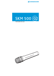
EK 500
SKM
Instructions for use
/
Thank you for choosing Sennheiser!
We have designed this product to give you reliable
operation over many years. Over half a century of
accumulated expertise in the design and manufacture of
high-quality electro-acoustic equipment have made
Sennheiser a world-leading company in this field.
Please take a few moments to read these instructions
carefully, as we want you to enjoy your new Sennheiser
product quickly and to the fullest.
2
Contents
The SKM 500 G2 radiomicrophone family ............................ 4
The channel bank system .................................................. 4
Safety instructions .................................................................... 5
Delivery includes ....................................................................... 5
Areas of application .................................................................. 6
The operating controls ............................................................. 7
Indications and displays .......................................................... 8
Preparing the radiomicrophone for use ............................. 10
Inserting/replacing the batteries .................................. 10
Changing the microphone head .................................... 11
Using the radiomicrophone .................................................. 13
Switching the radiomicrophone on/off ....................... 13
Muting the radiomicrophone ......................................... 14
Activating/deactivating the lock mode ....................... 14
The operating menu .............................................................. 15
The buttons ....................................................................... 15
Overview of menus .......................................................... 15
Working with the operating menu ............................... 16
Operating menu of the radiomicrophone .................... 18
Adjustment tips for the operating menu .......................... 20
Switching between channel banks ............................... 20
Switching between the channels in a channel bank . 20
Selecting the frequencies to be stored
in the channel bank “U” .................................................. 20
Adjusting the sensitivity ................................................ 21
Selecting the standard display ...................................... 22
Entering a name ............................................................... 22
Loading the factory-preset default settings .............. 22
Activating/deactivating the pilot tone transmission 23
Activating/deactivating the lock mode ....................... 23
Exiting the operating menu ........................................... 23
Troubleshooting ..................................................................... 24
Error checklist ......................................................... 24
Recommendations and tips ........................................... 25
Care and maintenance ........................................................... 26
Specifications .......................................................................... 27
Polar diagrams and frequency response curves
of microphone heads ....................................................... 28
Accessories .............................................................................. 29
Manufacturer declarations ................................................... 30
Warranty regulations ...................................................... 30
CE Declaration of Conformity ......................................... 30
Batteries or rechargeable batteries .............................. 30
WEEE Declaration ............................................................. 30
3
The SKM 500 G2
radiomicrophone family
The SKM 500 G2 radiomicrophone family is part of the evolution wireless series ew 500 G2. With this series, Sennheiser offers high-quality state-of-the-art RF transmission systems with a high level of operational reliability and
ease of use. Transmitters and receivers permit wireless
transmission with studio-quality sound. The excellent
transmission reliability of the ew 500 G2 series is based on
the use of
y further optimized PLL synthesizer and microprocessor
technology,
y the HDX noise reduction system,
y and the pilot tone squelch control.
The channel bank system
The radiomicrophone is available in five UHF frequency
ranges with 1440 transmission frequencies per frequency
range. Please note: Frequency usage is different for each
country. Your Sennheiser agent will have all the necessary
details on the available legal frequencies for your area.
Range
Range
Range
Range
Range
A:
B:
C:
D:
E:
518 to 554 MHz
626 to 662 MHz
740 to 776 MHz
786 to 822 MHz
830 to 866 MHz
The radiomicrophone has nine channel banks with up to 20
switchable channels each.
channel 1
preset frequency
channel 2
preset frequency
channel 20
preset frequency
channel 1
freely selectable frequency
channel 2
freely selectable frequency
channel 20
freely selectable frequency
channel bank 1...8
channel bank U
Each of the channels in the channel banks “1” to “8” has
been factory-preset to a transmission frequency (see
enclosed frequency table). These transmission frequencies
cannot be changed but have been preset so that e.g.
country-specific regulations on frequency usage are taken
into account.
The channel bank “U” (user bank) allows you to store your
4
selection out of 1440 transmission frequencies that are
freely selectable within the preset frequency range.
Safety instructions
Never open an electronic unit! If units are opened by
customers in breach of this instruction, the warranty
becomes null and void.
Use the unit in dry rooms only.
Use a damp cloth for cleaning the unit. Do not use any
cleansing agents or solvents.
Delivery includes
The packaging contains the following items:
y
y
y
y
y
1 SKM 500 G2 radiomicrophone
2 batteries
1 microphone clamp
Instructions for use
1 pouch
5
Areas of application
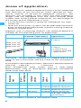
The SKM 500 G2 radiomicrophone family can be combined
with receivers of the ew 500 G2 series (EM 500 G2 rackmount receiver or EK 500 G2 bodypack receiver). The
receivers are available in the same five UHF frequency
ranges and are equipped with the same channel bank
system with factory-preset frequencies. An advantage of
the factory-preset frequencies is that
y a transmission system is ready for immediate use after
switch-on,
y several transmission systems can be operated simultaneously on the preset frequencies without causing intermodulation interference.
Together with a matching receiver, the radiomicrophone is
suitable for the following areas of application:
Transmitter
Receiver (to be
ordered separately)
EM 500 G2
SKM 535 G2 1 )
SKM 545 G2 1 )
SKM 565 G2 1 ) EK 500 G2
Area of
application
y Presentation
y Vocals
y
y
y
y
Speech
Vocals
Presentation
Camera-mounted
applications
The name1) of the radiomicrophone is a combination of the
name of the transmitter and the name of the microphone
head:
Transmitter+Microphone head = Name of radiomicrophone
SKM 500 +MD 835
= SKM 535
Transducer
principle
green
dynamic
cardioid Speech, vocals
MD 845
blue
dynamic
super- Vocals (high
cardioid feedback rejection)
ME 865
red
condenser super- Vocals (high
cardioid feedback rejection)
MMD 935 2) silver
(optional)
2)
6
dynamic
Area of
application
Color of i
dentification ring
MD 835
Picxk-up
pattern
Microphone
head
Each microphone head comes with a color-coded
identification ring to distinguish different microphone
heads from each other.
cardioid Vocals (in venues
with high ambient
noise levels)
only avilable as optional microphone head
The operating controls
Sound inlet basket
Color-coded identification ring for microphone heads
green: MD 835 microphone head
blue: MD 845 microphone head
red: ME 865 microphone head
Body of radiomicrophone
Battery compartment (not visible from outside)
Display section
LC display
Turnable protective cap for operating controls (shown
removed)
The following operating controls become accessible in
turn by turning the protective cap:
SET button
button (DOWN)
button (UP)
Red LED for operation and
battery status indication (ON/LOW BAT)
ON/OFF button
(serves as the ESC (cancel) key in the
operating menu)
MUTE switch
7
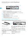
Indications and displays
LC display panel
Alphanumeric display
“B.CH“ – appears when the channel bank and
the channel number are displayed
“MHz“ – appears when the frequency is displayed
4-step battery status display
Lock mode icon
(lock mode is activated)
“PILOT” display
(pilot tone transmission is activated)
“MUTE” display
(audio input is muted)
7-step level display for audio signal “AF”
Operation and battery status indication
The red LED (LOW BAT/ON) provides information on the
current operating state of the radiomicrophone:
Red LED lit up:
The radiomicrophone is switched
on and the capacity of the
batteries/BA 2015 accupack is
sufficient.
Red LED flashing:
The batteries are/the BA 2015
accupack is going flat (LOW BAT)!
In addition, the 4-step battery status display on the
display panel provides information on the remaining
battery/BA 2015 accupack capacity:
3 segments:
capacity approx. 100 %
2 segments:
capacity approx. 70 %
1 segment:
capacity approx. 30 %
Battery icon flashing: LOW BAT
8
“MUTE” display
The “MUTE” display appears on the display panel when
the radiomicrophone is muted (see “Muting the
radiomicrophone” on page 14).
Modulation display
The level display for audio signal “AF” shows the
modulation of the radiomicrophone.
When the audio input level is excessively high, the level
display for audio signal “AF” shows full deflection for the
duration of the overmodulation.
“PILOT” display
The “PILOT” display appears on the display panel when
the pilot tone transmission is activated (see “Activating/
deactivating the pilot tone transmission” on page 23).
Display backlighting
After pressing a button, the display remains backlit for
approx. 15 seconds.
9
Preparing the radiomicrophone
for use
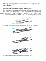
Inserting/replacing the batteries
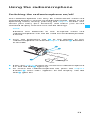
For powering the radiomicrophone, you can either use two
1.5 V AA size batteries or the rechargeable Sennheiser
BA 2015 accupack.
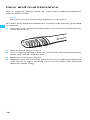
Unscrew the display section from the
radiomicrophone’s body by turning it counterclockwise.
Slide back the display section as far as it will go.
Open the battery compartment cover .
Insert the two batteries or the BA 2015 accupack as
shown. Please observe correct polarity when inserting
the batteries/accupack.
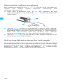
Close the battery compartment cover .
10
Push
the
battery
compartment
radiomicrophone’s body.
into
the
Screw the display section tight.
Note:
For accupack operation of the radiomicrophone, only use
the BA 2015 accupack in order to ensure optimum
operational reliability. For charging the accupack, only
use the L 2015 charger. Both the accupack and the
charger are available as accessories.
The accupack is fitted with an integrated sensor which is
– via a third contact – monitored by the electronics of
the radiomicrophone and the charger. The sensor is
necessary for the following control purposes:
y The taking into account of the different voltage
characteristics of primary cells (batteries) and
accupacks. The battery status indications on the
displays, the transmission of transmitter battery
status information to the rack-mount receivers and
the switch-off thresholds at the end of the operating
time are corrected correspondingly. Due to the
missing sensor, individual rechargeable battery cells
will not be identified as accupacks.
y The monitoring of the accupack temperature during
charging in the L 2015 charger.
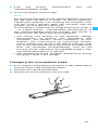
Changing the microphone head
First remove the batteries/accupack as described above
and leave the radiomicrophone open.
Unscrew the sound inlet basket.
Loosen the screw and put it to one side.
11
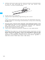
Gently ease the capsule out of the contacts and then pull
it out of the housing as shown. Do not touch the
contacts and the diaphragm!
Insert the new capsule.
Secure the capsule by tightening the screw.
Note:
The screw mechanically secures the microphone capsule.
If the screw is missing, malfunctions may occur during
tough use.
Put on the sound inlet basket and identification ring
supplied with the new microphone head (NB: do NOT use
the old basket, as the different heads use slightly
differing internal foam) and screw it tight.
Insert the batteries/accupack.
Close the radiomicrophone and put it into operation.
Note:
Microphone capsule, sound inlet basket and foam insert
form an acoustic unit and must therefore always be
exchanged all together. Each microphone head comes
with a color-coded identification ring to distinguish
different microphone heads from each other (green =
MD 835, blue = MD 845, red = ME 865).
12
Using the radiomicrophone
Switching the radiomicrophone on/off
The radiomicrophone can only be switched off when the
standard display is shown on the display panel. When in the
operating menu, briefly pressing the ON/OFF button will
cancel your entry (ESC function) and return you to the
standard display with the last stored settings.
Note:
Remove the batteries or the accupack when the
radiomicrophone will not be used for extended periods
of time.
Turn the protective cap at the bottom of the
radiomicrophone so that the ON/OFF button becomes
accessible.
Press the ON/OFF button to switch the radiomicrophone
on. The red LED lights up.
To switch the radiomicrophone off, press the ON/OFF
button until “OFF” appears on the display. The red
LED goes off.
13
Muting the radiomicrophone
The radiomicrophone has a MUTE switch that noiselessly
mutes the audio signal without switching the
radiomicrophone off.
Turn the protective cap at the bottom of the
radiomicrophone so that the MUTE switch becomes
accessible.
.
Set the MUTE switch to the position ’MUTE’. The “MUTE”
display appears on the radiomicrophone’s display panel.
Provided that the pilot tone function is activated on
both the transmitter and the receiver, the “MUTE”
display also appears on the receiver display panel.
Set the MUTE switch back to the original position to
retransmit the audio signal.
Activating/deactivating the lock mode
The radiomicrophone has a lock mode that can be activated
or deactivated via the operating menu (see “Activating/
deactivating the lock mode” on page 23). The lock mode
prevents that the radiomicrophone is accidentally
programmed or switched off during operation.
14
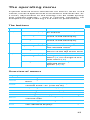
The operating menu
A special feature of the Sennheiser ew 500 G2 series is the
similar, intuitive operation of transmitters and receivers. As
a result, adjustments to the settings can be made quickly
and “without looking” – even in stressful situations, for
example on stage or during a live show or presentation.
The buttons
Buttons Mode
To...
ON/OFF Standard display
switch the radiomicrophone
on and off
Operating menu
cancel the entry and return
to the standard display
Setting mode
cancel the entry and return
to the standard display
Standard display
get into the operating menu
Operating menu
get into the setting mode of
the selected menu
Setting mode
store the settings and
return to the top menu level
Standard display
without function
Operating menu
change to the previous
menu ( ) or change to the
next menu ()
Setting mode
adjust the setting of the
selected menu:
option (/)
SET
/
Overview of menus
Display
Function of the menu
BANK
Switching between channel banks
CHAN
Switching between the channels in a channel
bank
TUNE
Setting a transmission frequency for the
channel bank “U” (user bank)
SENSIT
Adjusting the sensitivity (AF)
DISPLY
Selecting the standard display
NAME
Entering a name
RESET
Loading the factory-preset default settings
PILOT
Activating/deactivating the pilot tone
transmission
LOCK
Activating/deactivating the lock mode
EXIT
Exiting the operating menu and returning to
the standard display
15
Working with the operating menu
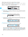
By way of example of the “TUNE” menu, this section
describes how to use the operating menu.
After switching the radiomicrophone on, the standard
display is shown on the display panel.
Getting into the operating menu
Press the SET button to get from the standard display
into the operating menu. The last selected menu flashes
on the display.
Selecting a menu
Press the / buttons to select a menu.
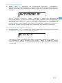
Press the SET button to get into the setting mode of the
selected menu. The current setting that can be adjusted
flashes on the display.
Adjusting a setting
Press the / buttons to adjust the setting.
By briefly pressing the / buttons, the display jumps
either forwards or backwards to the next setting. In the
“CHAN”, “TUNE ” and “NAME” menu, the / buttons
feature a “fast search” function. If you hold down a
button, the display cycles continuously, allowing you to
get fast and easily to your desired setting.
16
Storing a setting
Press the SET button to store the setting. “STORED”
appears on the display, indicating that the setting has
been stored. The display then returns to the top menu
level.
With most menus, new settings become effective
immediately without having to be stored. An exception
are the “BANK”, “CHAN”, “TUNE” and “RESET” menus.
With these menus, new settings only become effective
after they have been stored (“STORED” appears on the
display, indicating that the setting has been stored).
Exiting the operating menu
Select the “EXIT” menu to exit the operating menu and
to return to the standard display.
When in the operating menu, briefly pressing the ON/
OFF button will cancel your entry (ESC function) and
return you to the standard display with the last stored
settings.
17
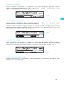
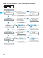
Operating menu of the radiomicrophone
SET
EXIT
BANK
SET
Changing the channel
bank
BANK 1
BANK U
Current channel bank
/ : 1...8, U (User
Bank)
SET: Stores the setting
STORED
CHAN
SET
1.03
B.CH
Current channel
(display depends on
"DISPLY" setting)
Changing the channel
B.CH
1.02
/ : Channel
01...20
SET: Stores the setting
STORED
TUNE
SET
790.025
MHz
Current frequency on
the selected channel
Setting the frequency
for channel bank "U"
791.125
MHz
/ : Transmission
frequency in steps of
25 kHz
SET: Stores the setting
STORED
SENSIT
SET
Setting the sensitivity
-10 dB
Current sensitivity
setting
-30 dB
/ :
0...-30 dB
SET: Stores the setting
STORED
SET
DISPLY
Switching between the
standard displays
FREQ
Current standard display
NAME
/ :
FREQ, NAME,
CHAN
SET: Stores the setting
STORED
NAME
18
DISPLY
NAME
SET
Assigning the
transmitter a name
VOCAL
Current transmitter name
STORED
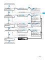
RESET
SET
RST. NO
Security check
Loading the factorypreset default settings
GUCAL
/ :
Transmitter name
(6 characters)
Letters w/o pronounciation
marks, numbers from 0...9,
special characters, spaces
SET: 5 x next character,
then store
RST. OK
/ : OK, NO
"reset" = OK:
SET: Transmitter loads
factory-preset default
settings (only pilot tone
setting is kept), transmitter
is restarted, standard
display appears
"reset" = NO
SET: Reset is cancelled
PILOT
SET
PLT. ON
Pilot tone transmission
activated or deactivated
Activating/deactivating
the pilot tone
transmission
PLT. OFF
/ : ON, OFF
SET: Stores the setting
STORED
LOCK
SET
LOC.OFF
OFF
Lock mode activated or
deactivated
Activating the lock mode
STORED
EXIT
LOC.ON
ON
/ : ON, OFF
Lock mode = ON:
SET: Stores the setting
("STORED"), returns to
standard display
Lock mode = OFF:
SET: Stores the setting
SET
Exiting the operating
menu
BANK
19
Adjustment tips for the
operating menu
Switching between channel banks – BANK
Via the “BANK” menu, you can switch between the
radiomicrophone’s nine channel banks. Each of the channel
banks “1” to “8” has up to 20 switchable channels that are
factory-preset to a transmission frequency (see “The
channel bank system” on page 4). The channel bank “U”
(user bank) has up to 20 switchable channels to store your
selection out of 1440 transmission frequencies that are
freely selectable within the preset frequency range .
When switching from one channel bank to another, the
channel with the lowest channel number is automatically
displayed.
Switching between the channels in a channel
bank – CHAN
Via the “CHAN” menu, you can switch between the different
channels in a channel bank. When switching between the
channels, please observe the following:
Always set the transmitter and the receiver of a
transmission link to the same channel.
Multi-channel operation
Combined with ew 500 G2 receivers, the radiomicrophone
can form transmission links that can be used in multichannel systems. For multi-channel operation, only use the
free channels in a channel bank.
Before putting the transmission links into operation, we
recommend performing an auto scan (see operating
manual of the receiver).
Selecting the frequencies to be stored
in the channel bank “U” – TUNE
Via the “TUNE” menu, you can select the frequencies to be
stored in the channel bank “U” (user bank) .
When you have selected one of the channel banks “1” to
“8” and then select the “TUNE” menu, the radiomicrophone
automatically switches to channel 01 of the channel bank
“U”.
20
In this case, “U.01” briefly appears on the display.
Use the / buttons to select the desired transmission
frequency. Transmission frequencies are tunable in
25-kHz steps within a switching bandwidth of 36 MHz
max. For intermodulation-free frequencies, please refer
to the enclosed frequency table.
Adjusting the sensitivity – SENSIT
Via the “SENSIT” menu, you
radiomicrophone’s input sensitivity.
can
adjust
the
The input sensitivity is adjusted too high when close talking
distances, speakers with loud voices or loud music passages
cause overmodulation in the transmission link. When the
audio input level is excessively high (AF peak), the level
display for audio signal “AF” shows full deflection.
If, on the other hand, the sensitivity is adjusted too low, the
transmission link will be undermodulated, which would
result in a signal with high background noise.
The sensitivity is correctly adjusted when the level display
for audio signal “AF” shows full deflection only during
the loudest passages.
Note:
For monitoring the adjusted sensitivity, the transmitter’s
level display for audio signal “AF” always indicates the
audio level – even if the transmitter is muted.
The following figures are a guide to the best settings:
y Loud music/vocals:
y Presentations:
y Interviews:
–30 to –20 dB
–20 to –10 dB
–10 to 0 dB
21
Selecting the standard display – DISLPY
Via the “DISPLY” menu, you can select the standard display:
Selectable standard display Contents of standard
display
“FREQ”
“NAME”
“CHAN”
Entering a name – NAME
Via the “NAME” menu, you can enter a freely selectable
name for the radiomicrophone. You can, for example, enter
the name of the performer for whom the adjustments have
been made.
The name can be displayed on the standard display and can
consist of up to six characters such as:
y letters (without pronounciation marks),
y numbers from 0 to 9,
y special characters e.g. () - . _ and spaces.
To enter a name, proceed as follows:
Press the SET button to get into the setting mode of the
“NAME” menu. The first segment starts flashing on the
display.
With the / buttons you can now select a character.
By briefly pressing a button, the display jumps either
forwards or backwards to the next character. If you hold
down a button, the display starts cycling continuously.
Press the SET button to change to the next segment and
select the next character.
Have you entered the name completely? Press the SET
button to store your setting and to return to the top
menu level.
Loading the factory-preset default
settings – RESET
Via the “RESET” menu, you can load the factory-preset default
settings. Only the selected setting for the pilot tone remains
unchanged. After the reset, the radiomicrophone is restarted
and the standard display is shown on the display panel.
22
Activating/deactivating the pilot tone
transmission – PILOT
Via the “PILOT” menu, you can activate or deactivate the
pilot tone transmisssion.
The pilot tone supports the receiver’s squelch function
(Squelch) and protects against interference due to RF
signals from other units. The transmitter adds an inaudible
signal, known as the pilot tone, to the transmitted signal.
The receiver detects and evaluates the pilot tone, and is
thus able to identify the signal of the matching transmitter
and mute all others.
Transmitters of the ew 500 series (first generation) do not
transmit a pilot tone and the receivers of the ew 500 series
(first generation) cannot evaluate the pilot tone.
Nevertheless, you can combine the radiomicrophone with a
receiver of the first generation. However, when combining
units, please observe the following:
y With the ew 500 G2 radiomicrophone and an ew 500 G2
receiver:
Activate the pilot tone function with both
radiomicrophone and receiver.
y With the ew 500 G2 radiomicrophone and an ew 500
receiver or vice versa:
Deactivate the pilot tone function with the ew 500 G2
radiomicrophone or receiver.
Activating/deactivating the lock mode – LOCK
Via the “LOCK” menu, you can activate or deactivate the
lock mode.
The lock mode prevents that the radiomicrophone is
accidentally programmed or switched off during operation.
The lock mode icon on the display indicates that the lock
mode is activated.
To deactivate the lock mode, first press the SET button and
then press the / buttons to select “LOC.OFF”. If you
confirm your selection by pressing the SET button, the
buttons can be operated as usual.
Exiting the operating menu – EXIT
Via the “EXIT” menu, you can exit the operating menu and
return to the standard display.
23
Troubleshooting
Error checklist
Problem
Possible cause
Possible solution
No
operation
indication
Batteries are flat or
accupack is flat
Replace the
batteries or
recharge the
accupack
No RF signal Transmitter and
receiver are not on
the same channel
Transmitter is out of
range
Set transmitter and
receiver to the same
channel
Check the squelch
threshold setting
or reduce the
distance between
transmitter and
receiving antenna
RF signal
available,
no audio
signal,
“MUTE”
display
appears on
the display
panel
Transmitter is muted Deactivate the
(“MUTE”)
muting function
Transmitter doesn’t
transmit a
pilot tone
Activate the pilot
tone transmission
Audio signal
has a high
level of
background
noise
Transmitter
sensitivity is
adjusted too low
See “Adjusting the
sensitivity” on
page 21
Receiver’s AF output
level is adjusted too
low
Increase the audio
output level
Receiver’s squelch
Reduce the squelch
threshold is adjusted threshold
too high
Audio signal Transmitter
is distorted sensitivity is
adjusted too high
Receiver’s AF output
level is adjusted too
high
See “Adjusting the
sensitivity” on
page 21
Reduce the AF
output level
If problems occur that are not listed in the above table or if
the problems cannot be solved with the proposed solutions,
please contact your local Sennheiser agent for assistance.
24
Recommendations and tips
... for the SKM 500 G2 radiomicrophone
y Hold the SKM 500 G2 in the middle of the microphone
body. Holding it close to the sound inlet basket will
influence the microphone’s pick-up pattern, holding it at
the lower part of the body will reduce the transmitter’s
range.
y You can vary the bass reproduction by increasing/
decreasing the talking distance.
y For best results, make sure that the transmitter
sensitivity is correctly adjusted.
... for optimum reception
y Transmission range depends to a large extent on location
and can vary from about 10 m to about 150 m. There
should be a “free line of sight” between transmitting and
receiving antennas.
y To avoid overmodulating the receiver, observe a
minimum distance of 5 m between transmitting and
receiving antennas.
... for multi-channel operation
y For multi-channel operation, you can only use the
channels in a channel bank. Each of the channel banks “1”
to “8” accommodates up to 20 factory-preset frequencies
which are intermodulation-free. For alternative frequency
combinations, please refer to the enclosed frequency table.
The freely selectable frequencies can be selected via the
“TUNE” menu and can be stored in the channel bank “U”.
y When using several transmitters simultaneously,
interference can be avoided by maintaining a minimum
distance of 20 cm between two transmitters.
25
Care and maintenance
Use a slightly damp cloth to clean the radiomicrophone
from time to time.
Note:
Do not use any cleansing agents or solvents.
To clean the radiomicrophone’s sound inlet basket, proceed
as follows:
Unscrew the sound inlet basket (turn counterclockwise)
and remove it.
Remove the foam insert.
Use a slightly damp cloth to clean the sound inlet basket
from the inside and ouside.
Reinsert the foam insert.
Replace the sound inlet basket on the radiomicrophone
and screw it tight (taking care not to loose the colored
identification ring).
26
Specifications
RF characteristics
Modulation
wideband FM
Frequency ranges
518–554, 626–662,
740–776, 786–822,
830–866 MHz
Transmission frequencies
Switching bandwidth
8 channel banks with up
to 20 factory-preset
channels each
1 channel bank with up to
20 freely selectable
channels (1440
frequencies, tunable in
steps of 25 kHz)
36 MHz
Nominal/peak deviation
± 24 kHz / ± 48 kHz
Frequency stability
≤± 15 ppm
RF output power at 50 Ω
typ. 30 mW
AF characteristics
Noise reduction system
Sennheiser HDX
AF frequency response
40–18,000 Hz
S/N ratio (at 1 mV and peak
deviation)
≥ 110 dB(A)
THD (at nominal deviation and ≤0.9 %
1 kHz)
Overall unit
Temperature range
– 10 °C to + 55 °C
Power supply
2 AA size batteries, 1.5 V
or BA 2015 accupack
Nominal voltage
2.4 V
Power consumption
y at nominal voltage
≤170 mA
y with switched-off transmitter ≤250 μA
Operating time
y with batteries
≥8h
y with BA 2015 accupack
≥8h
Dimensions [mm]
∅ 50 x 225
Weight (incl. batteries)
approx. 450 g
27
Microphone heads
MD 835
MD 845
ME 865
Transducer principle
dynamic
dynamic
condenser
Sensitivity
1.5 mV/Pa 1 mV/Pa
Pick-up pattern
Max. SPL
Color of
identification ring
3 mV/Pa
cardioid
supersupercardioid
cardioid
150 dB SPL 154 dB SPL 144 dB SPL
green
blue
red
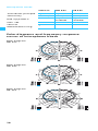
Polar diagrams and frequency response
curves of microphone heads
Polar diagram
MD 835
Polar diagram
MD 845
Polar diagram
ME 865
28
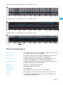
Frequency response curve MD 835
Frequency response curve MD 845
Frequency response curve ME 865
Accessories
MD 835
Microphone head (green identification
ring), dynamic, cardioid
MD 845
Microphone head (blue identification
ring), dynamic, super-cardioid
ME 865
Microphone head (red identification
ring), condenser, super-cardioid
MMD 935
Microphone head (silver identification
ring), dynamic, cardioid
MZW 1
Wind- and popshield
MZQ 1
Microphone clamp
BA 2015
Accupack
L 2015
Charger for BA 2015 accupack
CC 2
Carrying case for ew 500 G2 system
KEN
8 color-coded identification caps for
radiomicrophone
29
Manufacturer declarations
Warranty regulations
The guarantee period for this Sennheiser product is 24 months from the date
of purchase. Excluded are accessory items, rechargeable or disposable batteries that are delivered with the product; due to their characteristics these products have a shorter service life that is principally dependent on the individual
frequency of use.
The guarantee periodstartsfromthe date of original purchase. For this reason,
we recommend that the sales receipt be retained as proof of purchase. Without this proof (which is checked by the responsible Sennheiser service partner) you will not be reimbursed for any repairs that are carried out.
Depending on our choice, guarantee service comprises, free of charge, the
removal of material and manufacturingdefects through repair or replacement
of either individual parts or the entire device. Inappropriate usage (e.g. operating faults, mechanical damages, incorrect operating voltage), wear and tear,
force majeure anddefectswhichwere known at the time of purchase are excludedfrom guarantee claims. The guarantee is voidif the product ismanipulated
by non-authorised persons or repair stations.
In the case of a claim under the terms of this guarantee, sendthe device, including acces-sories and sales receipt, to the responsible service partner. To minimise the risk of transport damage, we recommendthat the original packaging
is used. Your legal rights against the seller, resulting from the contract of sale,
are not affected by this guarantee.
The guarantee canbe claimed in all countries outside the U.S. provided that no
national law limits our terms of guarantee.
CE Declaration
of Conformity
This equipment is in compliance with the essential requirements and other
relevant provisions of Directives 1999/5/EC, 89/336/EC or 73/23/EC. The
declaration is available on the internet site at www.sennheiser.com.
Before putting the device into operation, please observe the respective country-specific regulations!
Batteries or rechargeable batteries
The supplied batteries or rechargeable batteries can be recycled.
Please dispose of them as special waste or return themto your specialist dealer. In order to protect the environment, only dispose of
exhausted batteries.
WEEE Declaration
Your Sennheiser product was developed and manufactured with
highquality materials and components which can be recycled and/
or reused. Thissymbol indicates that electrical and electronic equipment must be disposed of separately from normal waste at the end
of its operational lifetime.
Please dispose of this product by bringing it to your local collection point or
recycling centre for such equipment. This will help to protect the environment
in which we all live.
30
Sennheiser electronic GmbH & Co. KG
30900 Wedemark, Germany
Phone +49 (5130) 600 0
Fax +49 (5130) 600 300
www.sennheiser.com
Printed in Germany
Publ. 02/06
090664/A2