1
Owner's
Manual
®
15.5 HP
ELECTRMC START
38" MOWER
AUTOMATIC
LAWN TRACTO
Model No.
917.271380
,, Safety
= Assembly
® Operation
,, Maintenance
,, Repair
Parts
CAUTION:
Read and follow all
Safety Rules and hstructions
before operating this equipmento
Sears, Roebuck
and Co., Hoffman
For answers to your questions
about this product, Call:
1o800-659-5917
Sears Craftsman Help Line
5 am - 5 pro, Mort - Sat
Estates, IL 60179
Maintenance .......................................
t8
Service and Adjustments ...................... 22
Storage ................................................
28
Troubleshooting .................................... 29
Repair Parts ......................................... 34
Parts Ordering ...................... Back Cover
Warranty ................................................
2
Safety Rules ........................................... 2
Product Specifications ........................... 5
Assembly ................................................ 6
Operation .............................................. 11
Maintenance Schedule ......................... 18
LIMITED TWO YEAR WARRANTY ON CRAFTSMAN
RIDING EQUIPMENT
For two (2) years from the date of purchase, if this Craftsman Riding Equipment is maintained, iubricated and tuned up according to the instructions in the owner's manuai,
Sears will repair or replace, free of charge, any parts found to be defective in material or
workmanship.
This Warranty does not cover:
Expendable items which become worn during normal use, such as blades, spark
plugs, air cleaners, belts, etc.
Tire replacement or repair caused by punctures from outside objects, such as nails,
thorns, stumps, or glass.
o Repairs necessary because of operator abuse, negligence, improper storage or accident or the failure to maintain the equipment according to the instructions contained in
the owner's manual.
, Riding equipment used for commercial or rental purposes.
LIMITED 90 DAY WARRANTY ON BATTERY
For ninety (90) days from date of purchase, if any battery included with this riding equipment proves defective in material or workmanship and our testing determines the bah
tery will not hold a charge, Sears will replace the battery at no charge. In-home warranty
service on your Craftsman riding equipment is available at no charge for 30 days from
the date of purchase. Please contact your nearest service center. After 30 days from the
date of purchase, warranty service is available by taking your Craftsman riding equipment to your nearest Sears Service Center. (In-home warranty service will still be avail*
able after 30 days from the date of purchase but a standard trip charge will apply). This
warranty applies only while this product is in the United States. This Warranty gives you
specific legal rights, and you may also have other rights which may vary from state to
state.
Sears, Roebuck and Co., D/817 WA, Hoffman Estates, IL 60179
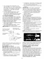
GENERAL OPERATION
® Read, understand, and follow all instructions in the manual and on the machine
before starting.
Only allow responsible adults, who are
familiar with the instructions, to operate
the machine.
• Clear the area of objects such as rocks,
toys, wire, etc., which could be picked
up and thrown by the blade.
o Be sure the area is clear of other people
before mowing. Stop machine if anyone
enters the area.
Never carry passengers.
Do not mow in reverse unless absolutely necessary. Always took down and
behind before and while backing.
Be aware of the mower discharge direction and do not point it at anyone. Do
not operate the mower without either
the entire grass catcher or the guard in
place.
® Slow down before turning.
Never leave a running machine unattended. Always turn off blades, set parking brake, stop engine, and remove
keys before dismounting.
2
o Turnoffblades
whennotmowing.
o Stopengine
before
removing
grass
catcher
or unclogging
chute
Mowonlyindaylight
orgoodartificia!
light
,, Donotoperate
themachine
whileunder
theinfluence
ofalcohol
ordrugs.
Watch
fortrafficwhenoperating
nearor
crossing
roadways.
,, Useextracarewhenloading
orunloadingthemachine
intoatrailerortruck.
SLOPEOPERATION
o Do not try' to stabilize the machine by
putting your foot on the ground.
Do not use grass catcher on steep
slopes.
thatyouwillnothavetostoporshift
whileontheslope.
,, Follow
themanufacturer's
recommendations
forwheel
weights
orcounterweights
toimprove
stability.
Useextracarewithgrasscatchers
or
otherattachments.
These
canchange
thestability
ofthemachine.
o Keepatlmovement
ontheo,,,Fe
......
andgradual.
Donotmakesudden
changes
inspeed
ordirection.
• Avoidstarting
orstopping
onaslope.If
tireslosetraction,
disengage
theblades
andproceed
slowlystraight
downthe
slope.
DONOT:
SERVICE
o Use extra care in handling gasoline and
other fuels_ They are flammable and
vapors are explosive.
Use only an approved container.
Never remove gas cap or add fuel
with the engine running. Allow engine to cool before refueling. Do not
smoke.
Never refuel the machine indoors.
Never store the machine or fuel
container inside where there is an
open flame, such as a water heater.
o Never run a machine inside a closed
area_
_, Keep nuts and bolts, especially blade
attachment bolts, tight and keep equip°
ment in good condition.
o Never tamper with safety devices.
Check their proper operation regularly.
o Keep machine free of grass, leaves, or
other debris build-up. Clean oil or fuel
spillage. Allow machine to cool before
storing.
o Stop and inspect the equipment if you
strike an object. Repair, if necessary,
before restarting.
CHILDREN
Tragic accidents can occur if the operator
is not alert to the presence of children.
Children are often attracted to the
machine and the mowing activity. Never
assume that children will remain where
you last saw them.
Keep children out of the mowing area
and -nder the watchfla! care of another
responsible adult.
of-control
andtipover
accidents,
which
,_ Be alert and turn machine off if children
canresultinsevere
injuryordeath.
All
slopes
require
extracaution.
Ifyoucannot enter the area.
backuptheslopeorifyoufeeluneasy
on ,, Before and when backing, look behind
and down for small children_
it,donotmowit.
[',lever carry children. They may fall off
DO:
and be seriously injured or interfere with
• Mowupanddownslopes,
notacross.
safe machine operation
,, Remove
obstacles
suchasrocks,
tree
Never allow children to operate the
limbs,
etc
,, Watch
forhotes,
ruts,orbumps.
Uneven machine.
terrain
couldoverturn
themachine.
Tall ,, Use extra care when approaching blind
corners, shrubs trees, or other objects
grasscanhideobstacles.
that may obscure vision.
,, Useslowspeed.
Choose
alowgearso
Do notturn on slopes unless necessary,
and then, turn slowly and graduaily
downhill, if possible.
o Do not mow near drop-offs, ditches, or
embankments. The mower could suddenly turn over if a wheel is over the
edge of a cliff or ditch, or if an edge
caves in.
o Do not mow on wet grass. Reduced
traction could cause sliding.
o Never
makeadjustments
orrepairs
with
theengine
running.
Grasscatcher
components
aresubject
towear,damage,
anddeterioration,
whichcouldexpose
moving
partsor
allowobjects
tobethrown.
Frequently
checkcomponents
andreplace
with
manufacturer's
recommended
parts,
whennecessary.
Mower
blades
aresharpandcancut.
WraptheMade(s)
orweargloves,
and
useextracaution
whenservicing
them.
Check
brakeoperation
frequently.
Adjust
andService
asrequired.
Besuretheareaisclearofotherpeople ® Mow up and down slopes (15 ° Max), not
before
mowing.
Stopmachine
ifanyone across.
Remove obstacles such as rocks, tree
enters
thearea.
limbs, etc.
Never
carrypassengers.
- Donotmowinreverse
unlessabsolute- Watch for holes, ruts, or bumps. Uneven
terrain could overturn the machine. Taft
lynecessary.
Always
lookdownand
behind
before
andwhilebacking.
grass can hide obstacles.
®Never
carrychildren.
Theymayfalloff
• Use slow speed. Choose a low gear so
andbeseriously
injured
orinterfere
with that you will not have to stop or shift
safemachine
operation.
while on the slope.
• Keepchildren
outofthemowing
area • Avoid starting or stopping on a slope. If
andunderthewatchful
careofanother tires lose traction, disengage the blades
responsible
adult.
and proceed slowly straight down the
- Bealertandturnmachine
offifchildren slope.
enterthearea.
Do notturn on slopes unless necessary,
and then, turn slowly and gradually
Before
andwhenbacking,
lookbehind
anddown for small children.
downhill, if possible.
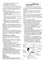
,_Look for this symbol to point out important safety precautions. It means CAUTION!!! BECOME AWARE!!! YOUR SAFETY IS INVOLVED.
_ACAUTION: In order to prevent accidental starting when setting up, transporting,
adjusting or making repairs always disconnect spark plug wire and place wire where
it cannot contact spark plug.
,_WARNING:
The engine exhaust from
this product contains chemicals known to
the State of California to cause cancer,
birth defects, or other reproductive harm.
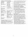
PRODUCT
SPECIFBCATIONS
GASOLINE 1.25GALLONS
CAPACITY
UNLEADED
AND
TYPE:
REGULAR
OILTYPE
SAEt0W30
APFSF/SG/SH):
(above
32°F)
SAE10W30
(below
32°F)
OILCAPACITY:4.0W/PINTS
3.5W/OPINTS
SPARK
PLUG: Champion
RC12YC
GAP:.040")
VALVE
CLEARANCE:
NOT ADJUSTABLE
GROUND SPEED
(MPH):
FORWARD: 0- 5.5
REVERSE: 0- 2.4
TIRE PRESSURE:
FRONT: 14 PSi
REAR: 10 PSI
CHARGING
SYSTEM:
3 AMPS BATTERY
5 AMPS HEADLIGHTS
BATTERY:
AMP/HR:
30
MIN. CCA:
240
CASE SIZE: U1R
BLADE BOLT
TORQUE:
27-35 FT. LBS.
CONGRATULATIONS on your purchase
of a Craftsman Tractor. It has been
designed, engineered and manufactured
to give you the best possible dependability
and performance.
Should you experience any problem wu___
cannot easily remedy, please contact your
nearest Sears Authorized Service Center.
We have competent, weiFtrained technio
cians and the proper tools to service or
repair this tractor_
Please read and retain this manual. The
instructions witl enable you to assemble
and maintain your tractor properly. Always
observe the "SAFETY RULES".
MAINTENANCE
AGREEMENT
A Sears Maintenance Agreement is available on this product. Contact your nearest
Sears store for details.
CUSTOMER
RESPONSIBIUTIES
Read and observe the safety rules.
Follow a regular schedule in maintaining, caring for and using your tractor.
,, Follow the instructions under"Maintenance" and "Storage" sections of this
owner's manual.
_WARNING:
This tractor is equipped
with an internal combustion engine and
should not be used on or near any unimproved forest-covered, brus,_.,-_,uv_,_u
....... .4 or
grass-covered land unless the engine's
exhaust system is equipped with a spark
arrester meeting applicable local or state
laws (if any). If a spark arrester is used, it
should be maintained in effective working
order by the operator.
In the state of California the above is
required by law (Section 4442 of the
California Public Resources Code). Other
states may have similar laws. Federal
laws apply on federal lands. A spark
arrester for the muffler is available through
your nearest Sears Aut_hodzed Service
Parts Bag contents shown full size
(1) Hex Bolt
3/8-16 x !
(1) Lockwasher
3/8
(t) Locknut
5/16-18
(1) Hex Bolt
(1) Large Flat Washer
5/16-18
x 1-1/4
(1) Shoulder
Bo!t 5/!6-18
(1) Knob
(1) Washer
17/32 x 1-3/16 x 12 Gauge
(1) Washer
13/32 x 1-1/4 x 16 Gauge
(1) Lock
Washer 3/8
(1) Wing Nut
3/8
Parts packed separately
in carton
Seat
Video
Cassette
Mulcher
Steering
Wheel
Plate
,1
i
Steering
Boot
P
Manual
Parts Bag
Parts Bag contents
not shown full size
Steering
Extension
Steering
Wheel
Insert
Shaft
Slope Sheet
(2) Keys
Steering Wheel
Adapter
Steering
Bushing
Assemblies
Your new tractor has been assembled at the factory with exception of those parts left,
unassembled for shipping purposes. To ensure safe and proper operation of your tractor
all parts and hardware you assemble must be tightened securely. Use the correct tools
as necessary to insure proper tightness. Review the video cassette before you begin.
TOOLS REQUIRED
FOR
ASSEMBLY
A socket wrench set will make assembly
easier. Standard wrench sizes you need
are listed below.
(1) 9/16" wrench
(1) 3/4" Socket w/
(1)Pliers
drive ratchet
m_ !/2" wrench
/_ Phillips _.......
(1) 3/4" wrench
driver
(1) Utility knife
(1) Tire pressure
gauge
When right or left hand is mentioned in
this manual, it means, from your point of
view, when you are in the operating position (seated behind the steering wheel).
TO REMOVE
CARTON
TRACTOR
FROM
UNPACK CARTON
Remove all accessible loose parts and
parts boxes from shipping carton (See
page 6).
o Cut, from top to bottom, along lines on
all four corners of shipping carton, and
lay panels flat.
• Check for any additional loose parts or
boxes and remove.
BEFORE ROLMNG TRACTOR OFF
SKiD
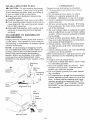
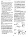
ATTACH STEERING WHEEL
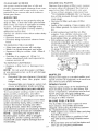
ASSEMBLE EXTENSION SHAFT AND
BOOT
,, Slide extension shaft onto lower steering shaft. Align mounting holes in extension and lower shafts and install 5/16
hex bolt and tocknut. Tighten securely.
iMPORTANT: Tighten bolt and nut securely to 18-22 ft. Ibs. torque.
® Place tabs of steering boot over tab
slots in dash and push down to secure.
INSTALL STEERING WHEEL
,, Position front wheels of the tractor so
they are pointing straight forward.
,, Slide steering wheel adapter onto steering shaft extension.
,, Position steering wheel so cross bars
are horizontal (left to right) and slide
inside boot and onto adapter.
Assemble large flat washer, 3/8 lock
washer, 3/8 hex bolt and tighten securely.
Snap steering wheel insert into center
of steering wheel.
Steering Wheel
Extension Shaft
5/16 Hex
5/16 Locknut
Lower
Steering_/_
Shaft
,,
&
-__-- -,,
"
"',
/
',,
<.'..-.. - -,/;"
Remove protective materials from tractor hood and grill.
IMPORTANT: Check for and remove any
staples in skid that may puncture tires
where tractor is to roll off skid.
TO ROLL TRACTOR OFF SKaD (See
Operation section for location and
function of controls)
* Press lift lever plunger and raise attachment lift lever to its highest position.
Release parking brake by depressing
clutch/brake pedal.
Place freewheel control in freewheeling
position to disengage transmission (See
"TO TRANSPORT" in the Operation
section of this manual).
, Roll tractor forward off skid.
, Remove banding holding discharge
guard up against tractor.
HOWTOSETUPYOURTRACTOR
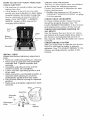
CHECK
BATTERY
Liftseatpantoraised
po'sition
andopen
battery
boxdoor.
tfthisbattery,
isputintosewiceafter
month
andyearindicated
onlabet(label
located
between
terminals)
charge
batteryforminimum
ofonehourat6-10
amps.(See"BATTERY"
inMA}NTEo
NANCE
section
ofthismanual
for
charging
instructions).
Seat
Pan
Label
Battery
Box
Terminal
iNSTALL SEAT
Adjust seat before tightening adjustment
knob.
Remove cardboard packing on seat pan.
• Place seat on seat pan and assemble
shoulder bolt. Tighten shoulder bolt
securely°
o Assemble adjustment knob and flat
washer loosely. Do not tighten.
0 Lower seat into operating position and
sit on seat.
• Slide seat until a comfortable position is
reached which allows you to press
clutch/brake pedal a!! the way down.
Get off seat without moving its adjusted
position.
• Raise seat and tighten adjustment knob
securely.
Shoulder
SeatPan
(_\_,
1/
Adn'oU:
'_
Washer
CHECK-.[ _HE PHESSUHL
The tires on your tractor were ovednflated
at the factory for shipping purposes.
Correct tire pressure is important for best
cutting pedormance.
® Reduce tire pressure to PSI shown in
"PRODUCT SPECIFICATIONS" on page
5 of this manual.
CHECK DECK LEVELNESS
For best cutting results, mower housing
should be properly leveled. See "TO
LEVEL MOWER HOUSING" in the Service
and Adjustments section of this manual.
CHECK FOR PROPER POSmON OF
ALL BELTS
See the
ures. _,=_a, _ o, ,,_..,, ,,_, ,_v,,_,.ing motion and mower blade drive belts in
the Service and Adjustments sectoin of
this manual. Verify that the belts are routed
correctly.
CHECK BRAKE SYSTEM
After you learn how to operate your tractor,
check to see that the brake is properly
adjusted. See "TO ADJUST BRAKE" in the
Service and Adjustments section of this
manual.
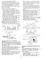
iNSTALLMULCHER
PLATE
_CAUTION:
Do not remove discharge
guard from mower Raise and hotd guard
when attaching mulcher plate and allow it
to rest on plate while in operation.
@ Raise and hold deflector shield in the
upright position.
@ Position alignment cup over rear baffle.
@ Pivot mulcher plate forward and hook on
mounting bolt. Be sure hang tab hooks
top of deck opening.
0 Assemble flat washer, lock washer and
wing nut to mounting bolt and tighten
securely.
TO CONVERT
DISCHARGING
TO BAGGING
OR
Simply remove mulcher plate and store in
a safe place. Your mower is now ready for
discharging or installation of optional grass
catcher accessory.
NOTE: If discharging or bagging results
are unsatisfactory with mulcher blades on
mower, remove the muicher blades and
install high performance discharging
blades, which are available at an authorized service center/department. (See
MOWER in the Repair Parts section of this
manual).
.... Mounting
....
Bolt
Deflector
Shield _
Mulcher
Plate
Fastening
Tab Slot
: /
I
i
I
Rear
Baffle
Alignment Cup
Deflector
Flat
Washer
Shield
Hang
if
Tab /
i
Lock
Washer
i
_9
Wing
Nut
Mulcher Plate
10
CHECKLIST
Please review the following checklist:
/ All assembly instructions have been
completed.
,/No remaining loose parts in carton.
,/Battery' is properly prepared and
charged. (Minimum 1 hour at 6 amps).
/ Seat is adjusted comfortably and tightened securely.
¢"All tires are properly inflated. (For shipping purposes, the tires were overinfiated at the factory).
¢" Be sure mower deck is properly leveled
side4o-side!front4o-rear
for best cutting
results. (Tkes must be properly inflated
for leveling).
,/Check mower and drive belts. Be sure
they are routed propedy around pulleys
and inside all belt keepers.
¢" Check wiring. See that al! connections
are still secure and wires are properly
clamped.
,/Before driving tractor, be sure freewheel
control is in drive position.
While learning how to use your tractor, pay
extra attention to the following important
items:
,/Engine oil is at proper level.
,/Fuel tank is filled with fresh, clean, regular unleaded gasoline.
,/Become familiar with all controls - their
location and function. Operate them
before you start the engine.
,/Be sure brake system is in safe operating condition.
,/It is important to purge the transmission
before operating your tractor for the first
time. Follow proper starting and transmission purging instructions (See "TO
START ENGINE" and "PURGE TRANSMISSION" in the Operation section of
this manual).
These symbols may appear on your tractor or in literature suppJied with the product
Learn and understand their meaning.
÷
J;
BATTERY
CAUTION
OR
REVERSE
FORWARD
OIL PRESSURE
CLUTCH
FAST
SLOW
WARNING
ENGINE
ON
ENGINE
OFF
LIGHTS
OVER TEMP
ON
LIGHT
G
FUEL
k
CHOKE
MOWER
HEIGHT
DIFFERENTIAL
LOCK
1
REVERSE
MOWER
LIFT
ENGAGED
DANGER,
KEEP
HIGH
L
(®>_i
LOW
PARKING
BRAKE
@@@@@
ATTACHMENT
ATTACHMENT
CLUTCH
NEUTRAL
UNLOCKED
PARKING
BRAKE
LOCKED
CLUTCH
KEEP
AREA
CLEAR
(SEE
HANDS
AND
SLOPE
HAZARDS
DISENGAGED
FEET
AWAY
IGNITION
SAFETY
RULES
SECTION)
FREE
(Automatic
11
WHEEL
Models
only)
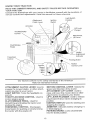
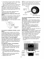
KNOWYOURTRACTOR
READ
TH!SOWNER'S
MANUAL
ANDSAFETY
RULES
BEFORE
OPERATING
YOUR
TRACTOR
Compare
theillustrations
withyourtractor
tofamiliarize
yourself
withthelocations
of
various
controls
andadjustments.
Savethismanual
forfuturereference,
Attachment
Clutch Lever
Ignition
Switch
Light Switch
Position
Ammeter
\
Lift Lever
Plunger
Throttle/Choke
Attachment
Lift Lever
Control _
Clutch/Brake
Pedal
Height
Adjustment
Indicator
Freewheel
Control
Parking Brake
Approx.
Speed
"
i
.
Motion
Control Lever
3 MPH
2 MPH
1 MPH
Our tractors conform to the safety standards of the American
National Standards Institute.
MOTION CONTROL LEVER: Selects the
speed and direction of the tractor.
ATTACHMENT LIFT LEVER: Used to
raise and lower the mower deck or other
attachments mounted to your tractor.
UFT LEVER PLUNGER: Used to release
attachment lift lever when changing its
position.
IGNITION SWITCH: Used for starting and
stopping the engine.
AMMETER: Indicates battery charging (+)
or discharging (-),
PARKING BRAKE: Locks clutch/brake
into the brake position.
ATTACHMENT CLUTCH LEVER: Used to
engage the mower blades, or other attachments mounted to your tractor.
LIGHT SWITCH: Turns the headlights on
and off,
THROTTLE/CHOKE
CONTROL: Used to
control engine speed.
CLUTCH/BRAKE PEDAL: Used for
declutching and braking the tractor and
starting the engine,
FREEWHEEL CONTROL: Disengages
transmission for pushing or slowly towing
the tractor with the engine off.
12
Theoperation
ofanytractor
canresultinforeign
objects
thrown
intothe
eyes,whichcanresultin severe eye damage. Always wear safety glasses
or eye shields while operating your tractor or performing any adjustments or
repairs. We recommend a wide vision safety mask over spectacles, or standard safety glasses°
HOW TO USE YOUR TRACTOR
slow position and allowing engine to idle
before stopping may cause engine to
"backfire _.
Your tractor is equipped with an operator
presence sensing switch. When engine is
running, any attempt by the operator to
leave the seat without first setting the
parking brake will shut off the engine.
Turn ignition key to "OFF' position and
remove key. Always remove key when
leaving tractor to prevent unauthorized
use.
TO SET PARKING BRAKE
,, Depress clutch/brake pedal into full
"BRAKE" position and hold
_, Place parking brake lever in "EN GAGED" position and release pressure
from clutch/brake pedal. Pedal should
remain in "BRAKE" position. Make sure
parking brake will hold tractor secure.
Throttle/Choke
Attachment Clutch Lever
Control
"Engaged" Position
"Disengaged"
Position
Clutch/Brake
Pedal "Drive"
Position
_--Motion
gaged"
Control
Position
Lever
STOPPING
MOWER BLADES To stop mower blades, move attachment dutch lever to "DISENGAGED"
position.
GROUND DRIVE To stop ground drive, depress
clutch/brake pedal into full "BRAKE"
position.
_, Move motion control tever to neutral (N)
position.
IMPORTANT: The motion'control lever
does not return to neutral (N) position
when the clutch/brake pedal is depressed.
ENGINE
Move throttle control to slow position.
NOTE: Failure to move throttle control to
13
o Never use choke to stop engine.
IMPORTANT: Leaving the ignition switch
in any position other than "OFF" will cause
the battery to be discharged, (dead).
NOTE: Under certain conditions when
tractor is standing idle with the engine running, hot engine exhaust gases may
cause "browning" of grass. To eliminate
this possibility, always stop engine when
stopping tractor on grass areas.
_, CAUTION: Always stop tractor completely, as described above, before leaving
the operator's position; to empty grass
catcher, etc.
THROTTLE CONTROL
Always operate engine at full throttle
- Operating engine at less than full throttle reduces the battery charging rate.
Full throttle offers the best bagging and
mower performance.
TO MOVE FORWARD AND BACKWARD
The direction and speed of movement is
controlled by the motion control lever.
Start tractor with motion control lever in
neutral (N) position.
* Release parking brake and clutch/brake
pedal.
Slowly move motion control lever to
desired position.
TO ADJUST MOWER CUTTING HEIGHT
The position of the attachment lift lever
determines the cutting height.
, Grasp lift lever.
Press plunger with thumb and move
lever to desired position.
The cutting height range is approximately
1-1/2 to 4". The heights are measured
from the ground to the blade tip with the
engine not running. These heights are
approximate and may vary depending
upon soil conditions, height of grass and
types of grass being mowed.
o If stopping is absolutely necessacj, push
dutch/brake pedal quicMy to brake posi o
tion and engage parking brake
Move motion control lever to neutraJ (N)
position_
IMPORTANT: The motion control lever
does not return to neutral (N) position
when the clutch/brake pedal is depressed.
o To restart movement, slowly release
parking brake and clutch/brake pedal.
SJowly move motion control lever to
slowest setting.
o Make all turns sJowty.
,, The average lawn should be cut to
approximately 21/2 inches during the
cool season and to over 3 inches during
hot months. For healthier and better
looking lawns, mow often and after
moderate growth_
o For best cutting performance, grass
over 6 inches in height should be
mowed twice. Make the first cut relatively high; the second to desired height°
TO OPERATE MOWER
Your tractor is equipped with an operator
presence sensing switch. Any attempt by
the operator to leave the seat with the
engine running and the attachment clutch
engaged will shut off the engine.
Select desired height of cut.
Start mower blades by engaging attachment clutch control
o TO STOP MOWER BLADES o disen-
TO TRANSPORT
When pushing or towing your tractor, be
sure to disengage transmission by placing
freewheel control in freewheeling position.
Freewheel control is located at the rear
drawbar of tractor.
,_ Raise attachment lift to highest position
with attachment lift control.
Pull freewheeJ control knob out and hold
in position by inserting retainer spring
into forward hole of control rod.
,, Do not push or tow tractor at more than
two (2) MPH.
,, To reengage transmission, reverse
above procedure.
NOTE: To protect hood from damage when
transporting your tractor on a truck or a
,_gage attachment clutch control.
CAUTION: Do not operate the mower
Attachment
Attachment Clutch
Lift
Lever High Position
Lever "Engaged"
Position
"Disenc
Position
_-._ Low
----\ Position
?
Discharge
Guard
trailer, be sure hood is closed and secured
to tractor. Use an appropriate means of
tying hood to tractor (rope, cord, etc.).
without either the entire grass catcher, on
mowers so equipped, or the discharge
guard in place.
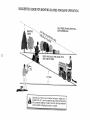
TO OPERATE ON HILLS
_CAUTION:
Do not drive up or down
hills with slopes greater than 15° and do
not drive across any slope. Use the slope
guide provided at the back of this manual.
,, Choose the slowest speed before starting up or down hills.
o Avoid stopping or changing speed on
hills.
• If slowing is necessary, move throttle
control lever to slower position.
TOWING CARTS
ATTACHMENTS
AND
OTHER
Tow only the attachments that are recommended by and comply with specifications
of the manufacturer of your tractor. Use
common sense when towing. Too heavy of
a load, while on a slope, is dangerous.
Tires can lose traction with the ground and
cause you to lose control of your tractor.
BEFORE
STARTING
THE ENGINE
CHECK ENGaNE OiL LEVEL
14
o The engine in your tractor has been
shipped, from the factob/, already fitted
with summer weight oiL
o Check engine oil with tractor on level
transmission engaged position.
o Sit _ _at in _8,_;
_r,,,
@_
dut_rake
_1
and _t _r'dng brake.
o Place motion control lever in neutral (N)
position.
Move attachment clutch to "DISENGAGED" position.
Move throttle control to choke position.
NOTE: Before starting, read the warm and
cold starting procedures below.
,, Insert key into ignition and turn key
clockwise to "START" position and
release key as soon as engine starts.
Do not run starter continuously for more
than fifteen seconds per minute, if the
engine does ........
"^" several
attempts, move throttle control to fast
position, wait a few minutes and try
again. If engine still does not start,
move the throttle control back to the
choke position and retry.
WARM WEATHER STARTING (50° F and
above)
,, When engine starts, move the throttle
control to the fast position.
- The attachments and ground drive can
now be used. If the engine does not
accept the load, restart the engine and
allow it to warm up for one minute using
the choke as described above.
COLD WEATHER STARTING ( 50 ° F and
below)
• When engine starts, allow engine to run
with the throttle control in the choke
position until the engine runs roughly,
then move throttle control to fast position. This may require an engine warmup period from several seconds to several minutes, depending on the temperature.
AUTOMATIC TRANSMISSION WARM UP
,, Before driving the unit in cold weather,
the transmission should be warmed up
as follows:
• Be sure the tractor is on level ground.
• Place the motion control lever in neutral.
Release the parking brake and let the
clutch!brake slowly return to operating
position.
o Allow one minute for transmission to
warm up. This can be done during the
engine warm up period.
• The attachments can also be used during the engine warm-up period after the
transmission has been warmed up.
NOTE: At a high altitude (above 3000
feet) or in cold temperatures (below 32 F)
the carburetor fuel mixture may need to be
,, Remove oil fil! cap/dipstick and wipe
clean, reinsed the dipstick and screw
cap tight, wait for a few seconds,
remove and read oil ievel. If necessary,
add oil until "FULL" mark on dipstick is
reached. Do not ovediJJ.
,, For cold weather operation you should
change oil for easier starting (See "OIL
VISCOSITY CHART' in the Maintenance section of this manual).
To change engine oil, see the Maintenance section in this manual.
ADD GASOLINE
,, Fill fuel tank. Use fresh, dean, regular
unleaded gasoline with a minimum of 87
octane. (Use of leaded gasoline will
increase carbon and lead oxide
deposits and reduce valve life). Do not
mix oil with gasoline. Purchase fuel in
quantities that can be used within 30
days to assure fuel freshness.
IMPORTANT: When operating in temperatures below 32°F(0°C), use fresh, clean
winter grade gasoline to help insure good
,_d weather starting.
WARNING: Experience indicates that
alcohol blended fuels (called gasohot or
using ethanol or methanol) can attract
moisture which leads to separation and
formation of acids during storage. Acidic
gas can damage the fuel system of an
engine while in storage. To avoid engine
problems, the fue! system should be emptied before storage of 30 days or longer.
Drain the gas tank, start the engine and let
it run until the fuel lines and carburetor are
empty. Use fresh fuel next season. See
Storage Instructions for additional information. Never use engine or carburetor
cleaner products in the fuel tank or permanent damage may occur.
_CAUTION:
Fill to bottom of gas tank
filler neck. Do not ovedill. Wipe off any
spilled oil or fuel. Do not store, spill or use
gasoline near an open flame.
TO START ENGINE
When starting the engine for the first time
or if the engine has run out of fuel, it will
take extra cranking time to move fuel from
the tank to the engine.
,, Be sure freewheel control is in the
15
adjusted
forbestengine
performance.
See"TOADJUST
CARBURETOR"
inthe
Service
andAdjustments
section
ofthis
manual
PURGE TRANSMISSION
CAUTION: Never engage or disengage freewheel lever while the engine is
running.
TO ensure proper operation and performance, it is recommended that the transmission be purged before operating tractor
for the first time. This procedure will
remove any trapped air inside the transmission which may have developed during
shipping of your tractor.
IMPORTANT: Should your transmission
require removal for service or replacement, it should be purged after reinstallation before operating the tractor.
,, Place tractor safely on level surface with
engine off and parking brake set.
Disengage transmission by placing freewheel control in freewheeling position
(See "TO TRANSPORT" in this section
of manual).
,, Sitting in the tractor seat, start engine.
After the engine is running, move throttle control to slow position. With motion
control lever in neutral (N) position,
slowly disengage clutch/brake pedal.
,, Move motion control lever to full forward
position and hold for five (5) seconds.
Move lever to full reverse position and
hold for five (5) seconds. Repeat this
procedure three (3) times.
NOTE: During this procedure there will be
no movement of drive wheels. The air is
being removed from hydraulic drive system.
o Move motion control lever to neutral (N)
position. Shut off engine and set parking
brake.
• Engage transmission by placing freewheel control in driving position (See
"TO TRANSPORT" in this section of
manual).
, Sitting in the tractor seat, start engine.
After the engine is running, move throttle control to half (1/2) speed. With
motion control lever in neutral (N) position, slowly disengage clutch/brake
pedal.
o Slowly move motion contro_ lever forward; after the tractor moves approximately five (5) feet, slowly move motion
control lever to reverse position. After
the tractor moves approximately five (5)
feet return the motion control lever to
the neutral (N) position. Repeat this pro °
cedure with the motion control lever
three (3) times°
o Your tractor is now purged and ready for
normal operation.
MOWING TIPS
,, Tire chains cannot be used when the
mower housing is attached to tractor.
o Mower shoufd be properly leveled for
best mowing performance. See "TO
LEVEL MOWER HOUSING" in the
Service and Adjustments section of this
manua!,
The !eft hand side of mower shoutd be
used for trimming°
Drive so that clippings are discharged
onto the area that has been cut. Have
the cut area to the right of the tractor.
This will resuJt in a more even distribution of clippings and more uniform cutting.
When mowing large areas, start by turning to the right so that clippings will discharge away from shrubs, fences, driveways, etc. After one or two rounds, mow
in the opposite direction making left
hand turns until finished.
,, if grass is extremely tall, it should be
mowed twice to reduce load and possible fire hazard from dried clippings.
Make first cut relatively high; the second
to the desired height.
Do not mow grass when it is wet. Wet
grass will plug mower and leave undesirable clumps. Allow grass to dry
before mowing.
,, Always operate engine at full throttle
when mowing to assure better mowing
performance and proper discharge of
material. Regulate ground speed by selecting a low enough gear to give the
mower the best cutting performance as
f
weII as the quality of cut desired.
When operating attachments, select a
ground speed that will suit the terrain
and give best performance of the attachment being used.
MULCHING
MUWI_#_!IH5
IMPORTANT:
For'bestpedormance,
keep
mowerhousing
freeofbuiltoup
grassand
trash.Cleanaftereachuse,
_,Thespecia!
mulchin
9bladewillrecur
thegrassclippings
many
timesand
reduce
theminsizesothatastheyfall
ontothelawntheywilldisperse
intothe
grassandnotbenoticedAlsothe
mulched
grasswillbiodegrade
quickly
toprovide
nutrients
forthelawno
Always
mulch
withyourhighest
engine
(blade)
speedasthiswillprovide
thebestrecuto
tingaction
oftheblades
,, Avoidcutting
yourlawnwhenitiswet.
Wetgrasstendstoformclumps
and
interferes
withthemulching
actionThe
besttimetomowyourlawnistheearly
17
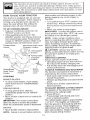
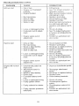
CUSTOMER RESPONSIBILITIES
MAINTENANCE
SCHEDULE
FiLL tN DATES
AS YOU COMPLETE
REGULAR
SERViC
===_ Check
Brake
E
Operatic
n
1
CheckOperatorP..... ceand
l..,
T[
interlock
|_!___:____l_
R
l C-he_oose
Systems
Fasteners
|
Clean
Battery
Check
Transaxle
Blade
Belt(s)
Motion
Drive
Check
Engine
r
Clean
Air
Screen
Clean
Spark
Air
Replace
Fuel
- Service
mote
If equipped
Replace
often
with
b_ades
GENERAL
(if
_d2
111,21
m-__
operating
when
under a heavy
operating
change
ofte_
when
_L_--
Cartridge
Filter
in dirty
oil
every
n_w_ng
or
50
n
dusty
load or in high ambient
conditions.
hoots,
sandy
_
temperatures.
IV"
_
_
mm
5 _ If equipped
with adjustable
system.
6 - Not required
if equipped with maintenance-free
7 - Tighten
front
axle
pivot
bolt
to
35
ft.dbs,
battery.
maximum.
Do not overtighten.
soil
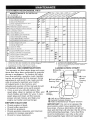
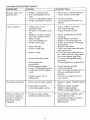
RECOMMENDATIONS
EACH
3
Fins
LUBRICATION
The warranty on this tractor does not cover
items that have been subjected to operator
abuse or negligence. To receive full value
from the warranty, operator must maintain
tractor as instructed in this manual. Some
adjustments will need to be made periodically to properly maintain your tractor.
All adjustments in the Service and
Adjustments section of this manual should
be checked at least once each season.
o Once a year you should replace the
spark plug, clean or replace air filter, and
check blades and belts for wear. A new
spark plug and clean air filter assure
proper air-fuel mixture and help your
engine run better and last longer.
BEFORE
ml
......... .+-----..-
equipped}
Paper
when
oi_ f_Iter,
more
--
PIug
Filter
more often
I
I
I
.....
Cooling
Replace
I
Arreste_
Filter
Replace
1_41
Tension
Level
Muffler/Spark
Engine
I
Tension
Oi!
Filter
Char_ge
-
Engine
Air
Oil
I
J
Belt(s)
Oi!
Clean
Replace
I
Terminals
Adjust
Inspect
I
Cooling
Adjust
Change
E
N
G
I
N
E
and
l
.............
A[
R
I
CHART
@ Spindle -- _____._,
Zerk
[i
J4"., -----'_"_ _
/_
./
_
@ Front Wheel , k/
I
Bearing Ze/_
@ Attachment I/1"
Clutch
J/ I
Pivot(s)
"'L
_-'=-=:-==-_
@ Spindle
Zerk
@ Front
Wheel
Bearing
rk
_-
@ SAE 30 or 10w30 Motor OIL
@ General Purpose Grease
O Refer to Maintenance "Engine" Section
USE
IMPORTANT: Do not oil or grease the
pivot points which have specia! nylon
bear-ings. Viscous lubricants will attract
dust and dirt that will shorten the life of the
self-lubricating bearings. If you feel they
must be lubricated, use only a dry, powdered graphite type lubricant sparingly.
- Check engine oil level.
Check brake operation.
• Checktire pressure.
- Check operator presence and interlock
systems for proper operation.
o Check for loose fasteners.
18
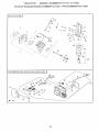
TRACTOR
iMPORTANT: To ensure proper assembJy,center ho_e in blade must align with
Always
observe
safetyruleswhenperstar on mandrel assembly.
forming
anymaintenance.
o ReassemMe hex bolt, lock washer and
BRAKE
OPERATION
flat washer in exact order as shown.
Iftractorrequires
morethansix(6)feet
,, Tighten bolt securely (27-35 Ft. Lbs.
stopping
distance
athighspeedinhighest torque).
gear,thenbrake
mustbeadjusted.
(See IMPORTANT: Blade bolt is Grade 8 heat
"TOADJUST
BRAKE"
intheService
and treated.
Adjustments
section
ofthismanual).
Mandrel
Trailing
Blade Star
TIRES
Edge Up_ .
\
- Maintain
proper
airpressure
inalltires
Flat
Washer_
(See"PRODUCT
SPEClF!CATIONS
'_
onpage5ofthismanual).
Hex Bolt
"_'_-_. _-_--_
Center
Keep
tiresfreeofgasoline,
oil,orinsect (Grade 8)* \__p i_'_'_u : i,
Ho,e
control
chemicals
whichcanharmrub__OCKWaS_ _er
ber.
*A Grade 8 heat treated bolt can be
identified by six lines on the bolt head.
TO SHARPEN BLADE
NOTE: We do not recommend sharpening
blade, but if you do, be sure the blade is
balanced.
Care should be taken to keep the blade
balanced. An unbalanced blade will cause
excessive vibration and eventual damage
to mower and engine.
The blade can be sharpened with a file
or on a grinding wheel. Do not attempt
to sharpen while it is on the mower.
® TO check blade balance, you will need a
5/8" diameter steel bolt, pin, or a cone
balancer. (When using a cone balancer,
follow the instructions supplied with balancer)
NOTE: Do not use a nail for balancing
blade. The lobes of the center hole may
appear to be centered, but are not.
,, Slide blade onto an unthreaded portion
of the steel bolt or pin and hold the bolt
or pin parallel with the ground, if blade
is balanced, it should remain in a horizontal position. If either end of the blade
moves downward, sharpen the heavy
end until the blade is balanced.
,, Avoid stumps, stones, deep ruts, sharp
objects and other hazards that may
cause tire damage.
NOTE: To seal tire punctures and prevent
flat tires due to slow leaks, tire sealant
may be purchased from your local parts
dealer. Tire sealant also prevents tire dry
rot and corrosion.
OPERATOR PRESENCE SYSTEM
Be sure that operator presence and interlock systems are working properly. If your
tractor does not function as described
below, repair the problem immediately.
The engine should not start unless the
clutch!brake pedal is fully depressed
and attachment clutch control is in the
disengaged position.
When the engine is running, any
attempt by the operator to leave the
seat without first setting the parking
brake should shut off the engine.
,, When the engine is running and the
attachment clutch is engaged, any
attempt by the operator to leave the
seat should shut off the engine.
The attachment clutch should never
operate unless the operator is in the
seat.
BLADE CARE
For best results mower blades must be
kept sharp. Replace bent or damaged
blades.
BLADE REMOVAL
, Raise mower to highest position to allow
access to blades.
Remove hex bolt, lock washer and f!at
washer securing blade.
Install new or resharpened blade with
trailing edge up towards deck as shown.
. Center Hole/x
5/8" Bolt
or Pin _
/
_ _,L_'_..
/
_
"_._7_-.[,<
BATTERY
Your tractor has a battery charging system
which is sufficient for normal use.
However, periodic charging of the battery
with an automotive charger will extend its
life.
19
o Keep
battery
andterminals
clean.
o Keepbattery
boltstight.
o Keepsmallventho_es
open.
Recharge
at 6-10amperes
for1hour.
TOCLEAN
BATTERY
ANDTERMINALS
Select the oil's SAE viscosity grade
Corrosion
anddirtonthebattery
andter- SHo
according
to your expected operating temminals
cancause
thebattery
to"leak"
perature
power.
Change the oitafter every 50 hours of
o Openbattery
boxdoor.
operation or at least once a year if the
Disconnect
BLACK
battery
cablefirst
thenREDbattery
cableandremove tractor is not used for 50 hours in one
year.
battery
fromtractor_
the crankcase oil level before startRinsethebattery
withplainwaterand Check
ing the engine and after each eight (8)
dry.
_ .....
_
_
"r_!,,_
• _ll _1_
o Clean
terminals
andbattery
cableends hours
stick
securely
each
time
you
check
the oil
withwirebrush
untilbright.
level.
Coatterminals
withgrease
orpetroleum
TO CHANGE ENGINE OIL
jelly.
Reinstall
battery
(See"REPLACING Determine temperature range expected
BATTERY"
intheSERVICE
AND
before oil change. All oil must meet API
ADJUSTMENTS
section
ofthismanu- service classification Stc, SG, or SH.
al).
Be sure tractor is on level surface.
NOTE:
Theoriginal
equipment
battery
on
Oil will drain more freely when warm.
yourtractor
ismaintenance
free.Donot
Catch oi! in a suitable container.
attempt
toopenorremove
capsorcovers. Remove oil fill cap/dipstick. Be careful
Adding
orchecking
levelofelectrolyte
is
not to allow dirt to enter the engine
notnecessary.
when changing oil.
Remove drain plug.
V-BELTS
After oil has drained completely, replace
Check
V-belts
fordeterioration
andwear
of! drain plug and tighten securely.
after100hours
ofoperation
andreplace
if
engine with oil through oil fill dipnecessary,
Thebeltsarenotadjustable. Refill
stick tube. Pour slowly, Do not overfill,
Replace
beltsiftheybegintoslipfrom
For approximate capacity see "PRODwear.
UCT SPECIFICATIONS" on page 5 of
TRANSAXLE
COOLING
this manual.
The transmission fan and cooling fins
should be kept dean to assure proper
cooling.
Do not attempt to clean fan or transmission while engine is running or while the
transmission is hot.
Inspect cooling fan to be sure fan
blades are intact and clean.
Inspect cooling fins for dirt, grass clippings and other materials. To prevent
damage to seals, do not use compressed air or high pressure sprayer to
clean cooling fins.
TRANSAXLE PUMP FLUID
The transaxle was sealed at the factory
and fluid maintenance isnot required for
the life of the transaxle. Should the
transaxle ever leak or require servicing,
contact your nearest authorized service
center.
ENGINE
LUBRiCATiON
Only use high quality detergent oil rated
with API service classification SF, SG, or
Use gauge on oil fill cap/dipstick for
checking level. Insert dipstick into the
tube and rest the oii fiii cap on the tube.
Do not thread the cap onto the tube
when taking reading.
Keep oil at
"FULL ° line on dipstick. Tighten cap
onto the tube securely when finished.
Air Cleaner
Cover
Cover Knob
Foam
Wing Nut
Grommet
Air
Cleaner
Paper
Cartridge
Air Cleaner
Base
,_L
Screen
Air
__
I,,,_
PO
......
_j Oil Fill
Cap/Dipstick
Oil Drain Plug
CLEAN
AIR SCREEN
Airscreen must be keptfreeofdidand
chafftopreventenginedamage fromover_.
heafing_ Clean wkh a wire brush or como
pressed air to remove did and stubborn
dried gum fibers
AIR FILTER
Your engine will not run properly using a
dirty air filten Clean the foam pre cteaner
after every 25 hours of operation or every
season. Service paper cartridge every
100 hours of operation or every season,
whichever occurs first.
Service air cleaner more often under dusty
conditions.
,_ Remove knob and cover.
,, Remove wing nut and ah cleaner from
base.
TO SERVICE PRE-CLEANER
o Slide foam pre-cleaner off cadridge
o Wash it in liquid detergent and water.
,, Squeeze it dry in a clean cloth Allow it
to dry.
o Saturate it in engine oil. Wrap it in
dean, absorbent cloth and squeeze to
remove excess oiL
ENGINE
OiL RLTER
Replace the engine oit filter even/season
or every other oil change if the tractor is
used more than 100 hours in one year.
- Drain ol from engine crankcase (See
"TO CHANGE ENGINE OIL '_in this sec o
tion of this manual, through step remove
drain plug).
o Remove oi! filter and wipe off filter
adapter.
Apply a thin coating of new engine oil to
the rubber gasket on replacement oil filter.
o Install replacement oil filter on filter
adapter. Turn oil filter clockwise until
rubber gasket contacts the filter adapter,
then tighten filter an additional t/'2 turn.
• Fill crankcase with new oil (See "TO
CHANGE ENGINE OIL" in this section
of this manual). For approximate capacity see "PRODUCT SPECIFICATIONS'
on page 5 of this manual.
o Start the engine and check for oil leaks.
Correct any leaks before placing engine
into fu!! operation.
TO SERVICE CARTRIDGE
o Replace a dirty, bent, or damaged cartridge.
NOTE: Do not wash the paper cartridge
or use pressurized air, as this will damage
the cartridge_
,,
Reinstall the pre-cleaner
(cleaned
and oiled)
over the paper cartridge.
MUFFLER
Inspect and replace corroded muffler and
spark arrester (if equipped) as it could create a fire hazard and/or damage.
o
SPARK
cL4
Reassembie
air cleaner, wing nut,
cover and tighten knob securely.
CLEAN AIR INTAKFJCOOLING AREAS
To insure proper cooling make sure the
grass screen, cooling fins, and other
externa! surfaces of the engine are kept
clean at alt times.
Every 100 hours of operation (more often
under extremely dusty, dirty conditions),
remove the blower housing and other
cooling shrouds. Clean the cooling fins
and external surfaces as necessary. Make
sure the cooling shrouds are reinstalled.
NOTE: Operating the engine with a
blocked grass screen, dirty or plugged
cooling fins, and/or cooling shrouds re=
moved will cause engine damage due to
overheating.
Oil Filter
PLUGS
Replace spark plugs at the beginning of
each mowing season or after even! 100
hours of operation, whichever occurs first.
Spark plug type and gap setting are
shown in "PRODUCT SPECIFICATIONS"
on page 5 of this manual.
IN-LINE FUEL FILTER
The fuel filter should be replaced once
each season. If fuel filter becomes
clogged, obstructing fuel flow to carburetor, replacement is required.
With engine coot, remove filter and plug
fuel line sections.
o Place new fuel filter in position in fuel
line with arrow pointing towards carburetor.
,, Be sure there are no fuel line leaks and
21
cfam.ps are properly positioned.
Keep
finished
surfaces
andwheels
free
ofal!gasoline,
oil,etc.
Protect
painted
surfaces
withautomotivetypewax.
Wedonotrecommend
usinga garden
hosetocleanyourtractor
unless
theetectrica!system,
muffler,
airfilterandcarburetorarecovered
tokeepwaterouLWater
inengine
canresultina shortened
engine
life.
FuelFilb
CLEANING
Cleanengine,
battery,
seat,finish,etc.
ofallforeign
matter.
,_CAUTION:
Before performing any service or adjustments:
,, Depress clutch!brake pedal fully and set parking brake.
,, Place motion control lever in neutral (N) position.
o Place attachment clutch in "DISENGAGED" position.
,, Turn ignition key "OFF" and remove key.
,, Make sure the blades and all moving parts have completely stopped.
Disconnect spark plug wire from spark plug and place wire where it cannot come in
contact with lu .
......
TO REMOVE MOWER
Mower will be easier to remove from the
right side of tractor.
,, Place attachment clutch in "DISENGAGED" position.
• Move attachment lift lever forward to
lower mower to its lowest position.
,, Roll belt off engine pulley.
Disconnect clutch rod from clutch lever
by removing retainer spring.
Clutch
Clutch Lever
Rod
"_
Retainer Spring Front
Disconnect antioswaybar from chassis
bracket by removing retainer spring.
Disconnect suspension arms from rear
deck brackets by removing retainer
springs°
o Disconnect front links from deck by
removing retainer springs.
Raise lift lever to raise suspension
arms. Slide mower out from under tractor.
IMPORTANT: If an attachment other than
the mower deck is to be, .....
,,,.,u,,,e,.,'
_ on the
tractor, remove the front links.
TO INSTALL MOWER
Raise attachment lift lever to its highest
position.
• Slide mower under tractor with discharge guard to right side of tractor.
• Lower lift lever to its lowest position.
- install mower in reverse order of
removal instructions.
Link
Retainer
Suspension
Spring!
Arms
Link
Suspension
Arms
/
Anti-Sway
Bar
Retainer
Springs
2P
TO LEVEL MOWER HOUSING
Adjust the mower while tractor is parked
on level ground or driveway. Make sure
tires are propedy inflated (See "PROD °
UCT SPECIFICATIONS')
_ftires are
over or undednflated, you will not properly
adjust your mower.
SIDE-TO-SIDE ADJUSTMENT
o Before making any necessary adjustments, check that both front links are
equal in length. Both links should be
approximately 10+3/8 ".
, If links are not equa! in !ength, adjust
one link to same length as other link.
o To lower front of mower toosen nut "E"
on both front links an equal number of
turns.
+ When distance "D + is 1!8" to 1!2++lower
at front than rear, tighten nuts "F+'
against trunnion on both front links.
+ To raise front of mower, loosen nut "F"
from trunnion on both front links.
Tighten nut "E" on both front links an
equal number of turns.
, When distance "D _ is I/8" to 1/2" lower
at front than rear, tighten nut "F" against
trunnion on both front links.
+ Recheck side4o-side adjustment.
, Raise mower to its highest position.
+ At the midpoint of both sides of mower,
measure height from bottom edge of
mower to ground. Distance "A" on both
sides of mower should be the same or
within 1/4" of each other.
+ If adjustment is necessary, make adjustment on one side of mower only.
+ To raise one side of mower, tighten lift
link adjustment nut on that side.
, To lower one side of mower, loosen lift
link adjustment nut on that side.
NOTE: Each full turn of adjustment nut
will change mower height about 1/8".
® Recheck measurements after adjusting.
BoSom
Bottom
__
of Curl
Mandrel
_'U"
Both Front Links Should be Equal in Length
C
Suspension
Arm
Nut "F"
!
Lift Link Adjustment
Nut
Trunnion
FRONT-TO-BACK ADJUSTMENT
IMPORTANT: Deck must be level side-toside if the following front-to-back adjustment is necessary, be sure to adjust both
front links equally so mower will stay
level side4o-side.
Front Links
TO REPLACE MOWER BLADE DRIVE
BELT
The mower blade drive belt may be
replaced without tools. Park the tractor on
level surface. Engage parking brake.
BELT REMOVAL , Place attachment clutch in "DISENGAGED" position.
+ Move attachment lift lever forward to
lower mower to its lowest position.
To obtain the best cutting results, the
mower housing should be adjusted so that
the front is approximately 1/8" to 1/2"
lower than the rear when the mower is in
its highest position.
Check adjustment on right side of tractor.
Measure distance "D" directly in front and
behind the mandrel at bottom edge of
mower housing as shown.
23
, Rollbeltoffengine
pulley.
o Disconnect
righthandsuspension
arm
fromreardeckbracket
byremoving
retainer
spfing_
Workbeltoffbothmandret
pulleys
and
idterpu_teys.
o Pullbeltaway
frommower.
BELTINSTALLATION
• installnewbeltinreverse
orderof
removal.
Makesurebeltisinallpulleygrooves
andinside
allbeltguides.
Suspension Arm
Engine
Pulley
Mandrel
Idler Pulleys
Retainer
Spring
JI
Mandrel
Pulley
TO ADJUST
./
....
o Measure distance between brake opero
ating arm and nut "A" on brake rod.
, If distance is other than 1-9/!6% loosen
jam nut and turn nut "A" until distance
becomes 1-9/16% Retighten jam nut
against nut "A".
® Road test tractor for proper stopping dis o
tance as stated above. Readjust if nec o
essary. If stopping distance is sti{_
greater than six (6) feet in highest gear,
further maintenance is necessary.
Contact your nearest authorized service
center/department.
TO REPLACE MOTION DRIVE BELT
Park the tractor on level surface, Engage
parking brake. For assistance, there is a
belt installation guide decal on bottom side
of _eftfootrest.
Remove mower (See "TO REMOVE
MOWER" in this section of this manual.)
• Remove belt from stationary idler and
clutching idler.
e Pull belt slack toward rear of tractor.
Carefully remove belt upwards from
transmission input pulley and over cooling fan blades.
, Pull belt toward front of tractor and
remove downward from around engine
pulley.
Installnew belt by reversing above procedure.
Engine Pulley ___,_\
BRAKE
Your tractor is equipped with an adjustable
brake system which is mounted on the
side of the transaxle.
If tractor requires more than six (6) feet
stopping distance at high speed in highest
gear, then brake must be adjusted.
o Depress clutch/brake pedal and engage
parking brake.
Clutching ,diet __)I'
Nut
)erating
Arm
Do Not touch this nut. If further brake adjustment is
r_n_nl
nnnt_nt vour nearest authorized service
TO ADJUST MOTION CONTROL LEVER
The motion control lever has been preset
at the factory and adjustment should not
be necessary.
If for any reason the motion control lever
will not hold its position while at a selected
speed, it may be adjusted at the friction
pack located On the right side of transmis-
Park:
tractoronlevelsurface.
Stoptraco NOTE: To seal tire punctures and prevent
totbyturning
ignition
keyto"OFF"
posF flat tires due to slow leaks, tire seatant
fion,andengage
parking
brake.
may be purchased from your local parts
Adjust
motion
control
leverbytighteningdealer. Tire sealant a_so prevents tire dry
adjustment
locknut
one,_,f(t/2)turn. rot and corrosion
NOTE:Ifforanyreason
theefforttomove
Washers
themotion
control
leverbecomes
too
excessive,
reverse
the above adjustment
Retaining
procedure by loosening Iocknut !/4 to !/2
turn.
Road test tractor after adjustment and
repeat procedure if necessary.
TRANSMISSION REMOVALfREPLACE_
MENT
Should your transmission require removal
for service or replacement, it should be
purged after reinstallation and before
operating the tractor. See "PURGE
TRANSMISSION" in the Operation section
of this manual.
Ring
1
Axle Cover
(Rear Wheel Only)
TO START
BATTERY
ENGINE
WITH A WEAK
ACAUTION:
Lead-acid batteries generate explosive gases. Keep sparks, flame
and smoking materials away from batteries. Always wear eye protection when
around batteries.
If your battery is too weak to start the
engine, it should be recharged. (See
"BATTERY" in the MAINTENANCE section of this manual)_
If "jumper cables" are used for emergency
starting, follow this procedure:
IMPORTANT: Your tractor Is equiped with
a 12 volt negative grounded system. The
other vehical must also be a 12 volt negative grounded system. Do not use your
tractor battery to start other vehicles.
TO ATTACH JUMPER CABLES ,, Connect each end of the RED cable to
the POSITIVE (+) terminal of each battery, taking care not to short against
chassis.
TO ADJUST STEERING WHEEL ALIGNMENT
If steering wheel crossbars are not horizontal (left to right) when wheels are positioned straight forward, remove steering
wheel and reassemble per instructions in
the Assembly section of this manual.
FRONT WHEEL TOE-IN/CAMBER
The front wheel toe-in and camber are not
adjustable on your tractor. If damage has
occurred to affect the front wheel toe-in or
camber, contact your nearest authorized
service center.
TO REMOVE WHEEL FOR REPAIRS
,, Block up axle securely.
,, Remove axle cover, retaining ring and
washers to allow wheel removal (rear
wheel contains a square key oDo not
lose).
Repair tire and reassemble.
o On rear wheels only: align grooves in
rear wheel hub and axle. Insert square
key.
o Replace washers and snap retaining
ring securely in axle groove.
,_ Replace axle cover.
Positive Terminal
Negative Terminal
;ables
Charged
Positive
25
Negative
Terminal
Connect
oneendoftheBLACK
cableto
theNEGATIVE
(o)termina_
offully
charged
battery.
o Connect
theotherend of the BLACK
cable to good CHASSIS GROUND,
away from fuel tank and battery.
TO REMOVE CABLES, REVERSE
ORDERBLACK cable first from chassis and
then from the fully charged battery.
REPLACING
BATTERY
ACAUTMON:
Do not short battery tero
minais by aiiowing a wrench or any
other object to contact both terminals
at the same time. Before connecting
battery, remove metal bracelets, wristwatch bands,rings,etc.
Lift seat pan to raised position and open
battery box door.
o Disconnect BLACK battery cable first
then RED battery cable and carefully
remove battery" from tractor.
Install new battery with terminals in
same position as otd battery_
First connect RED battery cable to positive (+) terminal with hex bolt and keps
nut as shown. Tighten securely.
Connect BLACK grounding cable to
negative (-) terminal with remaining hex
bolt and keps nut. Tighten securely.
o Close battery box door.
TO REPLACE HEADLIGHT BULB
o Raise hood.
o Pull bulb holder out of the ho_e in the
backside of the grill.
- Replace bulb in holder and push bulb
holder securely back into the hole in the
backside of the grill
o Close hood.
RNTERLOCKS AND RELAYS
Loose or damaged wiring may cause your
tractor to run poorly, stop running, or prevent it from starting.
o Check wiring, See electrical wiring dia o
gram in the Repair Parts section.
TO REPLACE FUSE
Replace with 30 amp automotive-type
plug-in fuse. The fuse holder is located
behind the dash.
TO REMOVE HOOD AND GRILL ASSEMBLY
, Raise hood.
Unsnap headlight wire connector.
o Stand in front of tractor. Grasp hood at
sides, tilt toward engine and lift off of
tractor
To replace, reverse above procedures.
Hood
\
Headlight
Wire
Connector
Seat
Pan
Battery
Door Box
ENGINE
Positive (Red)
C_
Keps Nut
Hex Bolt
Negative (Black) Cable
Maintenance, repair, or replacement of the
emission control devices and systems,
which are being done at the customers
expense, may be performed by any non °
road engine repair establishment or individual. Warranty repairs must be performed by an authorized engine manufacturer's service outlet.
TO ADJUST THROTTLE CONTROL
CABLE
The throttle control has been preset at the
factory and adjustment should not be neco
essaq#. Check adjustment as described
below before loosening cable. If adjustment is necessary, proceed as follows:
With engine not running, move throttle
control lever from slow to choke position Slowly move lever from choke to
fast position.
o Check to see if ho_e in throttle lever and
hole in speed control bracket are
aligned.
, If holes are not aligned, loosen cable
clamp screw and align the holes by
inserting a pencil or a 1/4" drill bit
through both holes.
• Pull throttle cable up to remove slack
and tighten cable clamp screw. Remove
alignment pencil or drill bit.
TO ADJUST CARBURETOR
The carburetor has been preset at the factory and adjustment should not be necessaPy. However, minor adjustment may be
required to compensate for differences in
fuel, temperature, altitude or load. If the
carburetor does need adjustment, proceed
as follows:
In general, turning the adjusting needles
in (clockwise) decreases the supply of fuel
to the engine giving a leaner fuel/air mixture. Turning the adjusting needles out
(counterclockwise) increases the supply of
fuel to the engine giving a richer fuel/air
mixture.
iMPORTANT: Damage to the needles and
the seats in carburetor may result if needle is turned in too tight
Idle _j
s_t_
o With throttle control
lever in s!ow position, engine shoutd
idle at 1750 RPM If engine idles too
slow or fast, turn idle speed adjusting
screw in or out unti! correct idle is ab
rained.
Idle fuel
- With throttle
control lever in slow position, turn idle
fuel adjustment needle in (clockwise)
until engine begins to die and then turn
out (counterclockwise) until engine runs
rough. Turn needle to a point midway
between those two positions.
Recheck idle speed. Readjust if necessat'y.
_bbLL_CL_RI
l%Jl'_
I _O
I
"
Move throttle control lever from slow to
fast position, if engine hesitates or dies,
turn idle fuel adjusting needle out
(counterclockwise) 1/8 turn. Repeat test
and continue to adjust, if necessary,
until engine accelerates smoothly.
High speed stop is factory adjusted. Do
not adjust - damage may result.
iMPORTANT: Never tamper with the
engine governor, which is factory set for
proper engine speed. Overspeeding the
engine above the factory high speed setting can be dangerous. If you think the
engine-governed high speed needs
adjusting, contact your nearest AUTHORIZED service center/department, which
has proper equipment and experience to
make any necessary adjustments.
Cable Clamp __
Screw
Speed Control
NOTE: The carburetor on this engine is
low emission. It is equipped with an idle
fuel adjusting needle with a limiter cap,
which allows some adjustment within the
limits allowed by the cap. Do not attempt
to remove the limiter cap.The limiter cap
cannot be removed without breaking the
adjusting needle.
Be sure you have a clean air filter and
the throttle control cable is adjusted
properly (see above).
Start engine and allow to warm for five
minutes. Make adjustments with engine
running and shift/motion control lever in
neutral (N) position.
_ll
_.___/._
Brackei_
Throttle Lever
tdle Speed
,diost,o0
Screw
_ _. :-----....__L,_
!
Idle Fuel
*diostlng -
eed,e
27
4__ylI
immediately
prepare
yourtractor
forstorageattheendoftheseason
orif the tractor will not be used for 30 days or more.
_CAUTION:
Never store the tractor with
gasoline in the tank inside a building
where fumes may reach an open flame or
spark. Allow the engine to cool before storing in any enclosure.
TRACTOR
Remove mower from tractor for winter
storage. This will a!!ow you to c!ean it thor°
oughly. Remove all dirt, grease, leaves,
etc. Store in a clean, dry area.
Clean entire tractor (See "CLEANING" in
the Maintenance section of this manual).
Inspect and replace belts, if necessary
(See belt replacement instructions in the
Service and Adjustments section of this
manual).
o Lubricate as shown in the Maintenance
section of this manual.
• Be sure that all nuts, bolts and screws
are securely fastened. Inspect moving
parts for damage, breakage and wear_
Replace if necessary.
, Touch up all rusted or chipped paint surfaces; sand lightly before painting.
BATTERY
• Fully charge the battery for storage.
- After a period of time in storage, battery
may require recharging.
, To help prevent corrosion and power
leakage during long periods of storage,
battery cables should be disconnected
and battery cleaned thoroughly (see "TO
CLEAN BATTERY AND TERMINALS" in
the Maintenance section of this manual).
,, After cleaning, leave cables disconnected and place cables where they cannot
come in contact with battery terminals.
- If battery is removed from tractor for
storage, do not store battery directly on
concrete or damp surfaces.
ENGINE
FUEL SYSTEM
iMPORTANT: It is important to prevent
gum deposits from forming in essential fuel
system parts such as carburetor, fuel filter,
fuel hose, or tank during storage. Also,
experience indicates that alcohol blended
fuels (called gasohol or using ethanol or
methanol) can attract moisture which leads
to separation and formation of acids during
storage. Acidic gas can damage the fuel
system of an engine while in storage.
on
Drain the fuet tank.
Start the engine and let it run until the
fuel lines and carburetor are empty.
Never use engine or carburetor cleaner
products in the fuel tank or permanent
damage may occur.
Use fresh fue! next season.
NOTE: Fuel stabilizer is an acceptable
alternative in minimizing the formation of
fuel gum deposits dudng storage. Add stabilizer to gasoline in fuel tank or storage
container. Always follow the mix ratio
found on stabilizer container. Run engine
at least 10 minutes after adding stabilizer
to allow the stabilizer to reach the carburetor. Do not drain the gas tank and carburetor if using fuel stabilizer.
ENGINE OIL
Drain oil (with engine warm) and replace
with clean engine oil (See "ENGINE" in
the Maintenance section of this manual).
CYLINDER(S)
Remove spark plug(s).
, Pour one ounce of oil through spark plug
hole(s) into cylinder(s).
Turn ignition key to "START" position for
a few seconds to distribute oil.
e Replace with new spark plug(s).
OTHER
,, Do not store gasoline from one season
to another.
• Replace your gasoline can if it starts to
rust. Rust and/or dirt in your gasoline will
cause problems.
If possible, store your tractor indoors
and cover it to give protection from dust
and dirt.
, Cover your tractor with a suitable protective cover that does not retain moisture.
Do not use plastic. Plastic cannot
breathe, which allows condensation to
form and cause your tractor to rust.
ff_PORTANT: Never cover tractor while
engine and exhaust areas are still warm.
TROUBLESHOOTING
CHART
PROBLEM
CAUSE
Wil!notstart
Out of fuel.
CORRECTION
Engine not _CHOKED"
properly.
,, Engine flooded.
o
o
o
o
Bad spark plug.
Dirty air fitter.
Dirty fuel filter.
Water in fuel
J ......
.....
.4
Luu_ u_ .4u_._y_u
wiring.
Carburetor out of adjustment.
Engine valves out of
adjustment°
Hardtostart
o Dirty air filter.
Bad <hark- ninon
° Weak or dead battery.
,, Dirty fuel filter.
, Stale or dirty fuel.
Loose or damaged wiring.
Carburetor out of adjustment.
Engine valves out of
adjustment.
Engine will not turn
over
o
o Fill fuet tank
See _TO START ENGINE" in
Operation section
Wait several minutes before
attempting to start.
o Replace spark plug.
o Clean/replace air filter.
Replace fuel filter.
,, Drain fuel tank and carburetor, refill tank with fresh
gasoline and replace fuel fiF
ter.
,_h_c_. _,, wiring.
o See "To Adjust Carburetor"
in Service and Adjustments
section.
,, Contact an authorized service center.
o Clean/replace air filter°
,, Replace spark plug.
Recharge or replace battery.
,, Replace fuel filter.
,, Drain fuel tank and refill with
fresh gasoline.
Check all wiring.
,, See "To Adjust Carburetor"
in Service and Adjustments
section.
o Contact an authorized ser vice center.
Clutch/brake pedal not
depressed.
Attachment clutch is
engaged.
Weak or dead battery.
Blown fuse.
Corroded battery terminals.
Loose or damaged wiring.
Faulty ignition switch.
o
Depress clutch/brake pedal.
@
o
Disengage attachment
clutch.
Recharge or replace battery.
Replace fuse.
Clean battery terminals.
Faulty solenoid or starter.
o
Faulty operator presence
switch(es).
o
Check all wiring.
ChecWreplace ignition
switch.
ChecWreplace solenoid or
starter.
Contact an authorized service center.
29
TROUBLESHOOTING
CHART
PROBLEM
CAUSE
Engine clicks
will not start
but
Loss of power
CORRECTION
,' Weak or dead battery.
Corroded battery terminals.
Loose or damaged wiring.
Faulty solenoid or starter.
Cutting too much
grass/too fast.
Throttle in ,,r-_
.... K6=,, posi,, Buitd_up of grass, leaves
and trash under mower.
,, Dirty air filter.
• Low oil level/dirty oil.
,, Faulty spark plug.
,, Dirty fuel filter.
,, Stale or dirty fuel.
o Recharge or replace battery.
Clean battery terminals.
,, Check all widng.
o ChecWreplace solenoid or
sta_rter.
o
o
o
,, Water in fuel.
,, Spark plug wire loose.
,, Dirty engine air
screen/fins.
,, Dirty/clogged muffler.
, Loose or damaged wiring.
,, Carburetor out of adjustment.
- Engine valves out of
adjustment.
Excessive vibration
,' Worn, bent or loose blade.
,, Bent blade mandrel.
Loose/damaged part(s).
Engine continues to
run when operator
leaves seat with at
tachment clutch
engaged
,, Faulty operator-safety
presence control system.
'3t_
e
Q
®
Set in "Higher Cut" position/reduce speed.
Adjust throttle control
Clean underside of mower
housing.
Clean/replace air filter.
Check oil level/change oil.
Clean and regap or change
spark plug.
Replace fuel filter.
Drain fuel tank and refill with
fresh gasoline.
Drain fuel tank and carburetor, refill tank with fresh gasoline and replace fuel filter.
Connect and tighten spark
plug wire.
Clean engine air screen/fins.
Clean/replace muffler.
Check all wiring.
See "To Adjust Carburetor" in
Service and Adjustments
section.
Contact an authorized service center.
,, Replace
bolt.
® Replace
,, Tighten
Replace
blade. Tighten blade
blade mandrel.
loose part(s).
damaged parts.
Check wiring, switches and
connections, if not
corrected, contact an authorized service center/
department.
_ROUBLESHOOTI_'_G
PROBLEM
Poor cut o uneven
CHART
I CORRECTION
CAUSE
- Worn,
bent or bose
Made°
o Mower deck not level
o Buildup of grass, leaves,
and trash under mower.
o Bent blade mandrel.
Clogged mower deck vent
holes from buitdup of
grass teaves, and trash
around mandrels.
Mower blades will
not rotate
Obstruction in clutch
mechanism.
o Worn/damaged mower
drive belt.
o Frozen idler pulley.
o Frozen blade mandrel.
Engine speed too slow.
Poor grass dis
charge
Travel speed too fast.
Wet grass.
Mower deck not level.
Low/uneven tire air pres i
sure.
Worn, bent or loose blade.
Buildup of grass, leaves
and trash under mower.
,, Mower drive belt worn.
Blades improperly
installed.
Improper blades used.
e
Clogged mower deck vent
holes from buildup of
grass, leaves, and trash
around mandrels,
bolt.
Level mower deck.
Clean underside of mower
housing.
o Replace blade mandrel.
o Clean around mandrels to
open vent hoies.
Remove obstruction.
Replace mower drive belt.
Replace idler pulley.
Reptace b_ade mandrel.
* Place throttle control in
"FAST" position.
° Shift to slower speed.
Allow grass to dry before
mowing.
Level mower deck.
,_ Check tires for proper air
pressure.
Replace/sharpen blade.
Tighten blade boll
Clean underside of mower
housing.
, Replace mower drive belt.
,_ Reinstall blades sharp edge
down.
Replace with blades listed in
this manual.
Clean around mandrels to
open vent holes.
Headlight(s) not
working (if so
equipped)
Switch is "OFF".
, Bulb(s) burned out.
Faulty light switch.
o Loose or damaged wMng.
o Blown fuse.
o Turn switch 'ON".
Replace bulb(s).
o ChecWreptace light switch.
o Check wiring and connections.
o Replace fuse.
Battery will not
charge
,, Bad battery cell(s).
o Poor cable connections.
Faulty regulator (if so
equipped).
,, Faulty alternator.
o Replace battery.
,, ChecWclean all connections.
o Replace regulator.
Q-I
o Replace alternator.
TF_OUBLESHOOT_
_HAH
PROBLEM
CAUSE
CORRECTION
Loss of drive
,, Freewheel control in "disengaged ° position
o Motion drive belt worn,
damaged or broken.
Air trapped in transmission dudng shipment
or servicing.
o Place freewheel control in
_engaged" position.
* Replace motion drive belt.
Engine "backfires"
when turning
engine "OFF"
Engine throttle control not
set at "SLOW _'
position for 30 seconds
before stopping engine.
32
o Purge transmission.
Move throttle control to
"SLOW _ position and aJlow
to idle for 30 seconds before
stopping engine.
TRACTOR-- MODELNUMBER917.271380
SCHEMATIC
nED
{
AMMETER
(OPTIONAL)
I
J
+GNmONp+_
PLOG m+ m
L .......... UNIT_'J {2 PLUGS
GAPON + +
+
_w_N
CYL.
E.G_NES>
J+
OPERATOR
PRESENCERELAY#2
28
Ct4_RGING
SYSlq_
M
OUTPUT
VOLTS
MIN
@ _
SYSTEM
DIODE
_:_/:+
RPM
DISCONNE
CTE
, ALTERNATOR|
DI
'
[
....................
T'--_'-_,_AFJ i +
OUTS:m
J7
+ A_p
AC
(C_RGING
A
AC
}
3+
_p+
14 VO[Tm
AC
+kN
e
+m
RpM
(LK',_TS
O+[}
+
NOTE
IGNITION SWITCH
YOUR 'TRACTOR IS
EQUIPPED WITH A SPECIAL
ALTERNATOR SYSTEM.
THE LIGHTS ARE NOT
CONNECTED TO THE
BATTERY, BUT HAVE THEIR
OWN ELECTRICAL SOURCE.
BECAUSE OF THIS, THE
BRIGHTNESS OF THE LIGHTS
WILL CHANGE WITH ENGINE
SPEED• AT IDLE THE LIGHTS
WILL DIM. AS THE ENGINE IS
SPEEDED UP, THE LIGHTS
RELAY
HEADLIGHTS
--O .....
ENGINE
CONNECTOR
WILL BECOME
THEIR BRIGHTEST.
REGULATOR
-,,
/--WIRING
INSULATED
CLIPS
NOTE: tF WIRING INSULATED CLIPS
¢¢ERE REMOVED FOR SERVICING OF
UNIT, THEY SHOULD BE REPLACED TO
PROPERLY SECURE YOUR WIRING•
(PURPLE W_RE,\
R£D WIRE)
CARBURETOR
SOLENOID
{REDWlRE,
BLUEWIRE)
['_:7"_£7_2_"
H_ _-+H
I_:::
F:_
_:
_::::_
_L2::_:_
N
33
--O .....
NON+REMOVABLE
CONNECTIONS
/
I
REMOVABLE
CONNECTIONS
TRACTOR
ENGINE
SHORTING
(WHITE WIRE}
IGNITION
BATTERY
"M" FOR ENGtNE-_
SHORTING
_._
/_
_CHARGING
: _:_
(RED W RE)
{BU'.O+':W,RE>
]lp-i F-_f]l
OILSENTRY
OILSENTRY
(GREENWRE
CONNECTOR
SWITCH
OPTION
{YELLOWWIRE
TO L}GHT PKG)
II_J
SWITCHED
_]1
+++_g_.[+
+_++rCZ]£
_
+12V
{BLUE WIRE)
TRACTOR o ° MODEL NUMBER 917.271380
ELECTRICAL
26
/
/
/
/
8/
34
TRACTOR
- - MODELNUMBER917.271380
i_LECTRJCAL
KEY
NO,
1
2
8
16
!9
PART
NO.
DESCRIPT_ON
163465
74760412
156417
161348
STD55! ! 25
Batter';i 12 Volt 28 Amp
Bolt, Hex Head 1/4-20 unc x 3/4
Case Battery Mech Hinge
Switch, interlock N Opr'JN Opn
Washer, Lock
20
21
22
24
25
26
27
28
29
30
31
32
33
40
41
42
43
73350400
147430
4152J
4799J
146147
108824X
73510400
4207J
160784
140301
124211X
141226
109310X
161352
71110408
131563
145673
Nut, Hex, Jam 1/4-20 UNC
Harness, Light Socket (includes 4152J)
Bulb, Light
Cable, Battery, 6 Gauge, Red, 11"
Cable, Battery, 6 Gauge, Red, W/16 Wire
Fuse, 30 Amp
['Jut, Keps Hex 1/4-20 Unc
Cable, Ground, 6 Gauge, Black, 12"
Switch Plunger Normal Op Olice
Switch, Ignition
Nut Ignition
Cover, Key' Switch
Key, Ignition
Harness, Ignition
Bolt, He× Head, Fin. 1/4-20 x 1/2
Cover, Terminal, Red
Solenoid
44
45
52
70
81
73640400
121433X
141940
142621
109748X
Nut Keps BIk Hex !/4-20 UNC
Ammeter Rectangular 6 Amp
Protection Wire Loop
Harness Engine
Relay Asm.
NOTE: All component dimensions given in U_S. inches
1 inch = 25.4 mm
35
TRACTOR o o MODEL NUMBER 917.271380
CHASSmSAND ENCLOSURES
28
12
58
53
55
57
14
54
3
/
3
36
14
TRACTOR
o o MODEL
NUMBER
917.27!380
4ASSES AND ENCLOSURES
KEY
PART
NO,
NO.
DESCRIPTmON
1
2
8
4
5
9
10
11
!2
13
!4
17
18
25
26
28
29
30
160392
140356
17490612
19131216
155272
161917X013
STb533710
155927
145660
155934X010
17490608
144983X558
126938X
19131312
STD541437
t48198X558
t55217X599
151287X558
Chassis Stamping
Drawbar
Screw Thd. Roll 3/8-16 x 3/4
Washer 13/32 x 3/4 x 16 Gauge
Bumper Hood/Dash
Dash
Bolt, Carriage 3/8-16 x 1
Panel, Dash L.H
Clip Titmerman Grille P/L
Panel, Dash. R.H.
Screw Thdrol 3/8-16 x 1/2
Hood Assembly
Bumper Hood
Washer 13/32 x 13/16 x 12 Gauge
Nut
Grille w/Clips MS-558
Lens, Gdlle
Fend/Ftrest Pnt STLT N HLD 558
31
37
38
39
51
52
53
54
55
57
58
60
64
74
139976
17490508
139886
139887
73800400
19091416
145201
161464
145202
STD522507
! 50127
72!40606
154798
73680600
Bracket, Fender Support
Screw Thdrol 51t6. 18 × !I2 Tyt
Pivot Bracket Assembly, LH.
Pivot Bracket Assembly, R.H.
Nut Lock w/Insert 1/4-20 UNC
Washer 9/32 x 718 x 16 Ga.
Bracket Grille Pickoff LH
ScrewHexWshd
8-18 x 7/8
Bracket Grille Pickofl RH
Bolt, Fin Hex 1/4-20 UNC x .75
Duct Air Engine P/[ LT
Bolt Rdhd Sqnk 3/8-.16 UNC x 314
Dash Lower STLT
Nut Crownlr_k 3/8-16 UNC
140
142
158418
156095
Bracket Suspension Front
Plate Reinforcement STLT
143
144
145
154.966
!54207
156524
Bracket Swaybar Chassis
Bracket Pnt Footrest STLT
RJod Pivot Chassis/Hood
5479J
Plug, Button
-NOTE:
All component dimensions given in U.S. inches
1 inch = 25.4 mm
tq7
I HA_
GROUND
I OH = = MULI_L
INUIViI_H
DRIVE
57
\
7t_
_,_--_"
16
38
IIII f°Zl
IJIU
TRACTOR
ooMODELNUMBER917.271380
GROUND
DR_VE
KEY
NO.
PART
NO.
1
2
3
8
10
16
150071
142431
143995
154792
76020416
73800500
18
74780616
19
73800600
21
22
24
25
26
27
28
29
30
32
34
35
36
37
38
39
4O
41
42
47
48
49
5O
51
52
53
55
56
57
59
61
130564
145627
73350600
106888X
19131316
76020412
145204
124236X
130807
74760512
15507 !
120183X
19211616
1572H
128674X
74760644
4470J
154777
19131312
127783
154407
123205X
74760624
73680600
73680500
1057!0X
105709X
74760620
140294
140312
17490612
62
63
64
65
66
8883R
140186
71170764
10040700
154778
KEY
NO,
DESCRmPT_ON
TransaxleAssembly
Spring, Return, Brake
Pulley. Transaxle
Rod Shift Hydro LT
Pin Cotter 1/8 x 1 CAD
Nut Leck Hex W/Ins. 5/16-18
Unc
Bolt Fin Hex 3/8o16 Unc x 1
Gr. 5
Nut Lock Hex W/Wsh 3/8-16
Unc
Knob, Deluxe I/2-13
Rod, Brake Hydro
Nut, Hex Jam 3/8-16 Unc
Spring Brake Rod
Washer
Pin Cotter 1/8 x 3/4 CAD.
Rod Parking Brake
Cap Parking Brake
Bracket, Transaxle
Bolt Hex Hd 5/16-18 Unc x 3/4
Shaft, Foot Pedal
Bearing, Nylon
Washer
Pin, Roll
Pulley, Idler, Flat
Bolt
Spacer, Split
Keeper, Belt Idler
Washer 13/32 x 13/16 x 12 Ca.
Pulley, Idler, V-Groove
Bellcrank, Clutch
Retainer, Belt
Bolt
Nut Crownlock 3/8-16 UNC
Nut. Crownlock 5/18-18 Unc
Link, Clutch
Spring, Return, Clutch
Bolt Hex 3/8-16 x 1-1/4
V-Belt, Ground Drive, Hydro
Keeper Center Span
Screw Thdrol. 3/8q6 x 3/4
Ty. TT
Cover, Pedal
Pulley, Engine
Bolt Hex 7/16-20 x 4 Gr. 5
Washer
Keeper Belt Engine Hydro
PART
NO,
DESCRIPTION
Keeper Belt Engine
Strap Torque Lh Hydro
18/20" T
Washer 13/32 x !-!/4 x 12 Ga.
Strap Torque Rh Hydro
! 8/20 "_T
70
71
134683
140158
72
73
19132012
156347
74
75
76
77
78
81
!2!199X
121749X
12000001
123583X
!21748X
156046
Spacer Split
Washer 25/32 x 1-!/4 x !6 Ca.
E-Ring
Key, Square
Washer 25/32 x 1-5/8 x 16 Ga.
82
83
84
86
87
88
89
90
93
94
95
96
97
123782X
19171216
161901
157480
19212016
12000008
158388
124346X
142564
140462
144643
4497H
140469
Spnng Torsion T/A
Washer 17/32 x 3/4 x 16 Ca.
98
100
102
73510600
19111216
141322
Nut Keps Hex 3/8-16 Unc
Washer 11/32 x 3/4 x 16 Ga.
Washer Bellville .501D x
1.50D
103
73940800
Nut Hex Jam Toptock 1/4_20
Unf
t04
I05
106
140156
71070516
74780520
Arm, Control Hydro
Screw Cap Hex 5/i6× i8x i
Bolt Fin Hex 5/16-18 Unc x 1t/4
Bolt Rdhd Sqneck 3/8-16 x
1.25
Washer 11/32 x 5/8 x 16 Ca.
116
72110610
144
145
146
19111016
74490540
74490536
147
148
74490524
159103
149
150
151
122052X
150935
19133210
Shaft Asm. Cross Hydro 20"
Tires
Rod, Tie Hydro 20" Tires
Bushing
Washer 21/32 x 1-1/4 x 16 Ca.
Ring Klip #5304-62
Console, Shift
Nut Self-Thd Wsh-hd 1/4 Zinc
Line Fuel Hydro 4"
Fan Hydro 7"
Control Bypass Hydro 20" Tires
Retainer Spring 1" Zinc/Cad
Keeper Bolt Rh Hydro 0750.
18/20"
Bolt Hex Flghd 5/16-18 x Gr. 5
Bolt Hex FIghd 5/16-18 x 2-1/4
Bolt hex Flghd 5/16-18 x 1-1/2
Spacer
Spacer, Retainer Pm Mower
Bushing Nylon Collered
Washer 13/32 x 2 x 10 Ca.
NOTE: All component dimensions
1 inch = 25.4 mm
39
given in U.S. inches
TRACTOR
o_o _ODEL
NUMBER
917o27!380
STEERING ASSEMBLY
!3
27
_17
(_
19
g
s
®
40
TRACTOR
o o MODEL
NUMBER
917.271380
STEERING ASSEMBLY
KEY
NO.
1
2
3
4
5
6
7
8
9
10
11
13
15
17
18
19
20
22
23
25
26
27
28
29
30
32
36
37
38
39
40
41
42
43
44
46
47
51
54
62
63
65
66
67
68
PART
NO.
DESCR_PTION
139768
154427
156483
157473
6266H
121748X
19272016
12000029
3366R
156438
STD551137
154779
73901000
156546
57079
124035X
126684X
71200410
Steering Wheel
Axle Assembly STMP Dropped STL
Spindle Assembly, LH.
Spindle Assembly, RH.
Beadng, Race, ThrusL Hardened
Washer 2_z32 x !-5/8 x !6 Gauge
Washer 27/32 x 1-1/4 x 16 Gauge
Ring, Kiip
Bearing Steering Column
Draglink Extended Stamped
'Washer, Lock
Bearing Axle STLT/GT
Nut, Lock, Flange 5/8-11 UNC
Shaft Assembly, Steering
Washer. Thrust .515 x .750 x .033
Support, Shaft
Washer, Shim 1/4 x 5/8 x .062
Screw Hex Socket !/4-20 x 5/8
1275,01
154406
126847X
136874
19131416
17490612
STD561210
! 30465
155099
152927
139769
19133808
STD541537
100711L
145054
121749X
153720
121232X
6855M
STD541431
74780520
156594
STD523710
154780
154404
74781044
154429
Pittman Shaft Assembly
Bracket, Steering
Bushing, Link, Drag
Gear, Sector
Washer 13/32 x 7/8 x 16 Gauge
Screw, Thd., Roll. 3/8-16 x 3/4
Pin
Rod, f]e
Bushing, Steering
Screw
Insert, Steering Wheel
Washer 13/32 x 2-3/8 x 8 Gauge
Gripco Nut
Adaptor, Steering Wheel
Boot, Steering Shaft
Washer 25/32 x 1- 1/4 x 16 Gauge
Extension Shaft Steering LR.LT
Cap, Spindle
Fitting, Grease
Nut Lock Hex w/ins. 5/16-18 UNC
Bolt Fin Hex 5/16-18 UNC x 1-1/4
Kit Steering Asm Service
Bolt Fin Hex 3/8-16 UNC x 1 Gr 5
Spacer Axle
Bearing Arm Pittman
Bolt, Fin Hex 5/8-ii UNC x 2-3/4
Axle, Brace
NOTE: All component dimensions given in U.S. inches
1 inch = 25.4 mm
41
TRACTOR
o o MODEL
NUMBER
9t 7o27t380
ENGmNE
I
i
8t
79
40
33
29
23
/
OPT!ONAL
EQUIPMENT
Spark Attester
_'_
42
35
TRACTOR
_oMODELNUMBER917,27t380
ENGINE
KEY
NO.
1
2
3
4
13
14
15
16
23
29
3!
32
33
35
37
38
40
44
46
62
77
79
80
81
101
PART
NO.
DESCRiPTiON
162158
17720410
......
159420
124341 .-03
Control, Throttle
Screw, Hex Head, Thread Cutting 1/4-20 x 5/8
Engine, (See Breakdown) Kohler Model No. CV 15S-41567
Muffler
Gasket Kohler CVl 3-CVl 6.5
13280328
13200300
STD551237
159880
Nipple, Pipe 3/8 NPT x 3-1/2
Elbow, Standard 90°, 3/8-18 NPT
Washer
Shield Bm/Dbr Guard
137180
109202X
158990
123487X
17490512
137040
.......
124028X
17490412
19091418
STD551131
19101216
M740108025
74760508
Arrestor, Spark
Tank, Fuel
Cap Assembly, Fuel Sears, Vented
Clamp, Hose
Screw Thdrol 5/16-18 x 3-4 Tyt
Line, Fuel
Plug, Oil Drain (Order From Engine Manufacturer)
Bushing, Snap, Fuel Line
Screw, Hex Washer Head, Thd., Roll. 1/4-20 x 3/4
Washer 9/32 x 7/8 x 16 Gauge
Washer, Lock
Washer 5/!8 x 3/4 x 16 Ga.
Bolt Hex
Bolt Hex Hd 5/16-18 Unc x 1/2
128861
M73030800
Nut Flange 1/4-20 Starter Nut
Nut Flange M8-1.25 Non-LK
A!! component dimensions given in U.S. inches
1 inch = 25.4 mm
4_
TRACTOR
o o MODEL
NUMBER
£17o271380
SEAT ASSEMBLY
®
11
KEY
NO.
1
2
3
4
5
6
7
8
9
10
1!
i2
PART
NO.
140123
140551
STD523710
19131610
145006
STD541437
124181X
17490616
19131614
155925
120068X
i2!246X
KEY
NO.
DESCRRPTION
Seat
Bracket, Pivot, Seat
Bolt
Washer 13/32 x 1 x 10 Gauge
Clip, Push-in Hinged
Nut
Spring, Seat
Screw, Thd., Roll. 3/8-16 x I
Washer 13/32 x 1 x 14 Gauge
Pan, Seat Emboss QCK Conn.
Knob Seat
Bracket, Switch Mounting
PART
NO,
13
14
!5
16
17
21
22
24
121248X
72050412
134300
121250X
123976X
153236
STD541431
19171912
25
127018X
DESCRIPTION
Bushing, Snap
Bolt, Carriage 1/4-20 x 1_1/2
Spacer, Split .28 x .88
Spring
Locknut, Flange 1/4 Grade 5
Bolt, Shoulder 5/16-18 UNC
Nut
Washer 17/32 x 1-3/16 x 12
Gauge
Bolt, Shoulder 5/16-18 x .62
NOTE: All component dimensions
I inch = 25.4 mm
44
given in U.S. inches
TRACTOR
ooMODELNUMBER'
917o271380
DECALS
7
1
21
6
!0
16
3
20
9
\
8
11
12
14
KEY
NO.
1
3
4
6
7
8
9
10
11
PART
NO.
156811
163200
163202
133644
163261
163203
163204
156439
142341
WHEELS
KEY
NO.
DESCRRPT!ON
Decal,
Decal,
Decal,
Decal,
Decal,
Decal,
Decal,
Decal,
Decal,
Lt
Oper. Instr.
Hood, RH.
Hood_ L H.
Customer Maintenance
Dash Panel
Deck Mower EZ3
Fender, Craftsman
Fender Danger
Drawbar Cntrl Mvt Hyd
& TIRES
PART
NO.
12
14
16
20
21
------
KEY
NO.
4,10
3,9
11
146046
136832
138047
149516
! 65186
138311
154515
154516
165203
165204
PART
NO.
DESCRRPTBON
Decal, V-Belt Drive Schematic
Decal, V-Belt Schematic
Decal, Battery Diehard
Decal, Battery Dngr/Psn Eng
Decal, Fender Auto
Decal, Lift Handle
Pad Footrest LH STLT
Pad Footrest RH STLT
Owner's Manual, English
Owner's Manual, Spanish
DESCRiPTiON
1
2
3
4
59192
65139
106222X
59904
5
6
7
8
106732X427
278H
9040H
106108X427
Valve Cap, Tire
Stem, Valve
Tire, Front
Tube Front Tire
(Not Provided, Service Item Only)
Rim, Front
Fitting, Grease (Front Wheel Only)
Beadng, Flange (Front Wheel Only)
Rim, Rear
9
10
122082X
7152J
Tire, Rear
Tube, RearTire
11
--
104757X
144334
(Not Provided, Service Item Only)
Cap, Axle
Sealant, Tire 10 oz.
NOTE: All component dimensions
1 inch = 25.4 mm
45
given in U.S. inches
TRACTOR o ° MODEL NUMBER 917o27t380
L_FTASSEMBLY
13
13
20
13
19
15
32
46
TRACTOR
°°
MODEL
NUMBER'
917o27t 380
LiFT ASSEMBLY
KEY
NO.
1
2
3
4
5
6
7
8
11
12
13
15
16
17
18
!9
20
31
32
PART
NO.
DESCRIPTION
159460
159471
105767X
Lift Lever inner Wire Assembly
Shaft Assembly, Lift
Pin, Groove
12000002
19211621
120!83X
125631X
122365X
139865
139866
4939M
127218
73350800
130171
73680800
139868
163552
140302
73540600
E-Ring
Washer 21/32 x I x 21 Gauge
Bearing, Nylon
Grip, Handle, Fluted
Button, Plunger, Red
Link. Lift LH.
Link, Lift RH.
Retainer Spring
Link, Front
Nut, Hex, Jam 1/2-13 UNC
Trunnion
Nut, Crownlock 1/2-13 UNC
Arm, Suspension, Rear
Retainer Spring
Bearing, Pvt, Lift Spherical
Nut, Crownlock 3/8-24
NOTE: All component dimensions given in U,S. inches
1 inch : 25.4 mm
47
TRACTOR
°_MODELNUMBEH931.21!_U
MOWER DECK
40
8£,+
78
77
"_"_67
107
75 ,._
_;_
-
141_
7-L_4
/
./
_ 80
45
72 _....
2
.c
69
71
_.._
81
89
56
"_/
-
,=f--._
78
_--_--
82
43
55 --_.._,
33
± _31
54--......
/
41_
o
"_'45
124
113
123...._._
100
53
30
21_,
__.,,_.88
28 26
d
?
w _
\
2
18 /
/
/-"
21
_
/,
/¸
48
J
TRACTOR o o MODEL NUMBER 9t7.271380
MOWER DECK
KEY
NOD
PART
NO.
1
2
3
142829
STD533107
13017
4
I38440
5
6
8
9
STD624008
130832
850857
STD651137
KEY
NO.
DESCRIPTION
10
140296
11
12
13
134148
129895
137645
14
15
16
19
21
23
128774
1i0485X
140329
132827
STD541431
137607
Mower Housing Assembly
Bolt, Carriage 5/16-18 x 3/4
Bracket Asm. Fram Sway Bar
38/42
Bracket, Asm. Deck Sway Bar
38_
Retainer, Spring
Asm. Suspension Rear
Bolt. He× 3J8-24 x 1-1/4 Gr. 8
Washer, Lock, Hvy Hlcl Spring
3/8
Washer, Hard Blade Mower
Vented
Blade, Mower, Mulching 38"
Bal! Bearing
Shaft and Beadng Assembty
(Includes Key Number 15)
Mandrel Housing, Vented
Ball Bearing, Mandrel
Stripper, Mower, Vented
Boll Shoulder
Nut, Crownlock 5/16-18
Bracket Mower Deflector
24
25
26
27
28
105304X
123713X
110452X
106736X
19111016
Cap, Sleeve
Spring, Deflector
Nut, Push
Shield, Deflector
Washer 11/32 x 3/4 x 16 Ga.
29
30
106735X
157722
Red, Hinge
Screw, Thdrol Washer Hd
31
32
33
36
129963
153532
137266
131494
Washer, Spacer
Pulley, Mandrel
Nut, Flangelock 9/16
Pulley, Idler, Flat
40
41
STD_1437
133551
Nut, Crownlock
Red, Pivot
43
45
53
54
133504
STD624003
130840
! 33943
Rod, Clutch, Secondary'
Retainer, Spring
Brake Assembly
Washer Hardened
55
56
87
88
89
133840
122052X
162113
144200
STD560907
idler Arm Assembly
Spacer, Retainer 1-3/4
Knob
Belt
Pin, Cotter 3/32 × 3/4
3/8-16
71
72
73
74
75
76
77
78
79
80
81
82
86
87
88
89
92
96
97
98
99
100
101
107
108
109
142427
131870
127847
121748X
12000029
128903
127845
160570
127498
153701
STD541237
142028
7631J
128772
19111216
19131612
STD541437
74930620
737506,90
19132016
10040600
135-651
132803
133502
133503
74760640
110
113
142587
17490512
122
123
131289
131288
124
128
129
!30
STD533717
153390
19131312
74780616
131
141
--
72140608
6266H
130794
-NOTE:
49
PART
NO.
142820
DESCRRPTION
Rod, Clutch Primary
Spring Return
Arm, Clutch, Secondary
Washer 25/32 x 1-5/8 x 16 Ga.
Ring, Klip
Bolt, Shoulder
Keeper, Spring
Arm, Clutch, Pr ma,ry
Bushing
Spring
Nut He× Jam 3/8-16 UNC
Trunnion Adj 94
Runner, LH
Runner, RH
Washer 11/32 x 3/4 x 16 Ga.
Washer 13/32 x 1 x 12 Ga.
Nut Lock Hex w/Ins 3/8-!6 UNC
Bolt
Washer
Washer
Lock Washer
Wing Nut
Mulcher Cover
Spacer Retainer
Stiffener. idler Arm
Bolt, Hex Read 3/8-16 x 2-t/2
Upstop Deck Front 38"
Screw, He× Head, Thd, Roll.
5/16-18 x 3/4
Rod, Brake, LH
Rod, Brake, RH
Bolt, Carnage 3/8-16 x 1-3/4
Washer Felt
Washer 13/32 x 13/16 x t2 Ga.
Bo!t Fin Hex ?J8-!6 Unc _ 1
Gr. 5
Bolt Rdhd Sqnk 3/8-16 Unc x 1
Washer Thrust .75 x 1.230
Mandrel Assembly (Includes
Key Numbers 12-15, t7-t9, 31
and 33)
Mower Deck, Complete
All component dimensions
1 inch = 25.4 mm
given in U.S. inches
TRACTOR
HYDRO GEAR TRANSAXLE
o o MODEL
NUMBER
917o27t380
o- MODEL NUMBER 319--0650
1
27
28
59
26
\52
4
5
3
35
113
5O
TRACTOR°oMODELNUMBER9!7o271380
HYDRO
GEAR
TRANSAXLE
o°MODEL
NUMBER
3t9_0650
KEY
NO,
PART
NOo
DESCRIPTION
1
142980
Rousing, Lower
2
3
4
5
6
7
8
9
13
14
15
17
18
19
23
24
25
26
27
28
29
30
34
35
36
37
38
39
40
41
142931
142932
142928
142933
1429_
142935
!.E©771
142937
142938
142939
142940
142941
150772
150773
142944
142945
142946
150774
142948
142949
142950
150787
142951
142952
142953
1429_
142955
150777
150778
142958
KEY
NO.
Assembly, Upper Housing
Sea!. Lip
Ring, Wire Retaining
Ring, Retaining
Bearing Shaft Ball
Bearing, Cradle
Bearing, Thrust 30 x 52 x !3
Swashp!ate, Variable
Block, Cylinder Assembly
Arm, Trunnion
Seal Lip
Guide_ S!ot
Shaft, Motor
Bearing, Thrust 42 x 68 x 16
Block, Cylinder Assembly
Seal Lip t0 x 25 x 7
Actuator_ %_ass
Center Section Assembly Kit
Sea!, Lip 26 × 42 x 8
Ring Retairfing
Washer 26 x 35 x 1
Plate, Bypass
Oil Filter Element
Arm, Bypass
Ring, Retaining
Arm, Actuating
Pin, Actuating
Bolt 5/16-24 x !-3/4
Locknut, Hex 5/16-24 UNJC
Brake RotoriStator Ki_
PART
NO.
DESCRIPTION
43
142884
Washer
44
52
53
56
58
59
62
63
64
68
69
88
85
88
89
90
91
92
93
113
!14
119
134
I35
139
140
15[)829
142991
142961
142963
142964
142965
142966
142967
142920
142969
144610
142971
15[)806
142973
142974
142975
142976
142977
142978
142917
142918
142980
144607
144608
150775
150776
Jackshafl Assembly
Jackshafl
Screw. Cap
Washer 7/16 × I x 1/2
Sleeve Bearing
Seal, Wiper
Spring Block
Washer, Black Thrust
Cap, Vent Assembly
Fitting, O Ring Assembly
Spacer
Nut, Castle 5/16-24
Pin, Cotter
Spring, Compression
Nut, Hex 5/t6-24
NOTE: All component dimensions
1 inch = 25.4 mm
51
7/!6 x 7/8 x .060
Differentia/Assembly
Washer 3/4 x 15 x .13
SeaI .75 x 1.25 x .250
Shall Input
Bolt t/420x
t 38
Pin 50D x .43/D x .750
Arm Controt
Puck, Darnpen_r
Set Screw
Spring
Stud 5/16.24
given in U.S. inches
TRACTOR
ooMODELNUMBER
£17o917o271380
KOHLER
ENGmNEoMODEL
NUMBER
CVI5S,TYPENUMBER
PS-4t567
AIR
_NTAKE
I
_j>-.......
...........
,
_
6 ......
I
............5
e
£'I
8--2:._ ........
,,_j\}:i,:] --
ENGINE
">
CONTROLS
r
I----9
9
CRANKSHAFT
[
'o
EXHAUST
2
(i_,o__I '_
,,s\ i _.;toV
-°
I
I j
@../- S
/
6
52
TRACTOR
° ° MODEL NUMBER 917.917.271380
KOHLER ENGINE-MODEL HUMBER CV15S, TYPE NUMBER PS-4!567
ENGINE CONT£OLS
AIR INTAKE
KEY
NO.
PART
NO.
1
12-743°05
2
3
4
5
6
7
25-34t-02
12-096-24
12-0834)8
!2-100-01
Xo25-63
12-083-05
8
9
12-313-04
12-094-12
10
12-072-05
11
12-086-01
12
12-041-02
NOT ILLUSTRATED
-12-113-53
KEY
NO.
DESCRRPTION
Kit, Air Cleaner
(includes Key Numbers 2 thru
12)
Knob, Air Cleaner Cover
Cover, AirCleaner
Predeaner Element
Wing Nut
Washer. Plain 1/4
Element Air Cleaner (Includes
#7)
Grommet
Base, Air Cleaner
(Includes Key Numbers 9 and
10)
Stud, Mounting Plate M6 x 1.0 x
66
Screw, #10 Hi-Lo Thread
Forming (2)
Gasket, Air Cleaner
1
2
PART
NO.
DESCRIPTION
12-014-37
12-139-01
Crankshaft
Plug, Cup
PART
NO.
1
M-O545010
2
3
4
24-468-10
12o146-07
M-0645020
6
7
9
8
10
11
24-096-05
12-027-32
12-141-01
!2-096-28
25-154-02
M-0545020
12
13
12-063-05
M-0645016
4
5
M-0545016
12-536-09
6
7
8
9
10
11
12
M4:)443020
SM-0443025
12-089-11
12-089-23
12089-24
M4:)64 t060
SM-0642025
13
14
15
16
12-090-05
25-158-11
12-079-01
25-158-08
KEY
NO.
1
2
3
4
5
6
DESCRIPTION
Screw, Hex Flange
M5xO8x
10(8)
Washer, Plain 1/4
Plate, Blower Housing
Screw, Flex Flange M6 x 1.0 x
20
Cover, Pinion
Housing, Blower
Ring, Retainer (2)
Cover
Clip, Mounting (3)
Screw, Hex Flange M5 x .8 x 20
DESCRIPTION
Linkage, Choke
Clamp, Cable
Screw_ Locked Socket
M6 x !0 x 20 (2)
Screw. Hex Flange M5 x .8 x 16
Control, Speed Assembly
0ncludes Key Numbers 6
through 9)
Screw. Pan Head M4 x 0.7 x 20
Screw, Pan Head M4 x 07 x 25
Spring, Choke Adjust (2)
Spring, Choke Return
Spdng, Governor
NuL Bex Flange M6 x 1.0
Screw, Hex Flange
M6x 1.0 x 25
Lever Governor
Bushing, Throttle Linkage
Linkage, Throttle
Bushing, Linkage Retaining
PART
NO.
M-0829033
12-041-03
M-0841080
12-126-11
12-445-06
M-0645025
DESCRIPTION
Stud, M8 x 1.25 x 33 (2)
Gasket, Exhaust Manifold
Nut, Hex Flange M8 x 1.25 (2)
Bracket, Muffler
Strap, Lifting
Screw, Hex Flange
M6 x 1.0 x 25 (2)
NOT ILLUSTRATED
-12-522-18
-12-755-59
Short Block
Gasket Set
RPM Settings:
RPM Settings:
Low Speed: 1500-2000
High Speed: 3200-3400
NOTE: All component dimensions
1 inch = 25.4 mm
(3)
14
12-063-08
15
12-063-01
NOT mLLUSTRATED
-12-113-64
12-079-07
!2-237-01
M-0664020
EXHAUST
BLOWER HOUSING AND BAFFLES
KEY
NO.
1
2
3
Decal, Air Cleaner
CRANKSHAFT
KEY
NO.
PART
NO.
Baffle, Intake Side
Screw, Hex Flange
M6x 1.0x 16 (2)
Baffle, Cylinder Head
Baffle, Cylinder
Decal, Horsepower
53
given in U.S. inches
TRACTOR
- oMODELNU_IBER
917o917o271380
KOHLER
ENGINE-MODEL
NUMBER
CV15S,
TYPENUMBER
PSo41567
FUELSYSTEM
I
4
/
/
4
2o t
-- 25
33
- 27
Qm29
31
CYLINDER
HEAD,
VALVE
AND
BREATHER
]
17
14
15
/
54
/
3O
TRACTORooMODELNUMBER9q7o917.27t380
KOHLER
ENG_NEo_4ODEL
NUMBER
CV15S,
TYPENUMBER
pSo41567
FUELSYSTEM
CYUNDER HEAD_VALVE AND BREATHER
KEY
NO,
KEY
NO.
PART
NO_
1
12-85356
2
3
12-041_02
12-053_5B
4
5
6
7
8
9
10
11
12
13
14
15
16
17
18
19
20
1243414) t
12.089-23
12.-079-07
12-265 04
X-426@
25-353-10
25-05002
4715.401
12--08607
12431-01
12-368@5
12-089- 09
12-086-04
12o089-09
12-146-03
25_086-27
12-144_09
21
22
23
24
25
26
27
28
12, 144-08
I2-089q0
12-!46-02
12-337.03
12-757-02
12-041 _05
12.-I04o01
12757409
29
12041-06
30
M-0641060
31
X-25-63
32
X-22-11
33
M-0629122
NOT mLLUSTRATED
-12-041-01
-12-757-03
-12518@5
--
41-518-34
-°
--
277563
12-454-03
DESCRIPTION
Nit. Carbure or (tnc/udes #2 thru
6)
Gasket, Air C_eaner
Carburetor Assembly
(For Information Only ° Not
Available Separately)
(Includes Key Numbers 12 thru
2'7)
Gasket, Carburetor (2)
Spring, Choke Return
Linkage, Choke
Deflector, Heat
Clamp, Hose (2)
Line_ Fuel, 9 _
Filter, Fuel
Clip Cabie
Screw, He× Cap 8-32 x 3/8
Sleeve, Insulating
Need!e, Idle, FuelAdjust
Spring idle Fuel
Screw, Idle Speed Adjust
Spring, idle Speed
Plate, Throttle
Screw, Throttle Plate (2)
Shaft, Throttle with Lever and
Sea!
Shaft, Choke
Spring, Choke
Plate, Choke
Jet, Main
Kit, Float
Gasket, Bowl
Bowf, Fue!
Kit, Solenoid Assemb!y
(Includes Key Number 29)
Gasket, Bow! Retainer Screw
Nut Hex Flange M6 x !.0 (2)
Washer, Plain 1/4
Washer, Lock 1/4
I
2
3
4
5
PART
NO.
DESCR[PTmON
7
8
9
10
12-351-01
12-75560
12-41t-0i
12 04 t-10
12-017-01
12@17-O2
!2-016-0!
12-016-02
I2-146i3
!2-468-05
12qt2 13
12-086-15
11
12
12-089-0!
12q7301
13
14
15
16
12-75503
X-426-9
12-32603
M-0645020
17
18
19
12-096-07
235011
24-032-05
20
M-0640034
Screw, Rex Flange M6 x 1 x 34
(2)
21
22
23
24-194-0t
24-186-03
M-0545010
24
12-018-01
Pivot. Rocker Arm (2)
Arm, Rocker (2)
Screw, He× Flange
M5 x 08 x t0
Retainer. Breather Reed
25
26
27
12-402.02
12-318-09
X-75-23
Reed, Breathe_
Head, Cylinder
Plug, Pipe, Aflen Head 1/8
6
Lifter, Valve (2)
Kit, Cylinder Head
Rod Push (2)
Gas[,et, Cy@derHead
Valve, Intake, Standard Size
Valve, Intake, .25" Oversize
Valve, ExhausL Standard
Valve, Exhaust, 25' Oversize
Plate, Guide
Wasf er, Plain i3/32
Spacer, Head Bolt Exhaust Port
Screw, Hex Flange
M10 x 1 5 x 81 (5)
Spring, Valve (1)
Cap, Valve bprl_"
r_g(2)
Kit Retainer (2)
Clamp, Hose (2)
Hose Breather
Screw, Hex Flangr
M6 x 1 0 x 20 (5)
Cover, Valve with Nipple
Retainer Spring
Seal Valve Stem
NOTE: All component dimensions
1 inch = 25.4 mm
Stud, M6 x 1.0 x 122 (2)
Gasket Carburetor
[(it, Carburetor Repair
Lead, Solenoid, Black, 5", 14
Gauge Uninsulated Push-On
Tabs
Lead, Ground, Green, 5", 18
Gauge Insulated Grip Barrel
Eyelets
Connector
Tie, Cable
55
given in U.S. inches
TRACTOR
- - MODELNUMBER917,917.271380
KOHLER
ENGJNIE-MODEL
NUMBER
CV15S,
TYPENUMBER
PS-41567
iGNiTION
PAN / LUBRICATION
I ELECTRICAL_
jJ
_'q
S
2
__
I
+
,2--
?
?
L/_-
)
=4--
I
=-@BQ
CRANKCASE
['STARTING
I
SYSTEM
@
g
56
_J
[
!--+
TRACTOR
° o MODEL
KOHLER ENGINE-MODEL
NUMBER
9t7o917o271380
NUMBER CV15S, TYPE NUMBER
iGNITION / ELECTRICAL
CRANKCASE
KEY
NO.
KEY
NO.
PART
NO.
1
12-086-14
2
3
4
12-468-03
24-162-03
M-06390!6
5
6
7
8
9
10
12-112-01
12-157-02
X-42-15
12.025-37
12-155-02
M-0548025
11
M-0545010
12
13
14
15
!6
17
!2-154.02
12-085-07
12-132-02
X-728-1
12-584-01
M.0545020
DESCRIPTION
Screw, Hex Flange
M10 × 1.5 x 46
Washer, Plain 3/8
Screen, Grass
Screw, Hex Flange M6 x 1 x 16
(4)
Spacer, Fan (4)
Fan
Key
myw_ee_ _ssemu_y
Connector (4 Contact)
Screw, He× Cap
M5 x 0.8 x 25 (2)
Screw, Hex Flange
M5 × 0.8 x 10 (2)
Clip, Stator Harness
Stator Assembly
Spark Plug
Clip, Cable
Module, Ignition
'Screw, Hex Flange
M5 x 0.8 x 20 (2)
NOT ILLUSTRATED
--
12-518-!1
Lead, White, Ground To Kil! (!9",
18 Gauge, Fully Insulated Pushon Tab and Uninsulated Push-on
iTab Terminals)
OaL PAN / LUBRICATION
KEY
NO.
PART
NO.
DESCRIPTION
1
12-038-01
Dipstick Assembly
(Includes Key Numbers 2 and 3)
Kit, Oi! Fill Cap (Includes Key #3)
O-Rin4j, Dipstick
O-Ring, Upper Oil Fill Tube
Tube, Oil Fill
Screw, Hex Flange M5 x 0.8 x
2O
2
3
4
5
6
25-755-!3
12=153-03
I2-153-02
12-!23.04
M-0545020
7
8
9
10
12-153-01
25-162.07
12-098-03
M.0545016
O-Ring, Lower Oil Fill Tube
Screen, Oil Pick-up
Cover, Oil Pick-up Screen
Screw, Hex Flange M5 x 0.8 x
11
M-1039025
12
12-!26-02
16
Screw, Hex Flange M10x 1.5x
25
Bracket, Oi! Pump Relief Valve
13
14
15
12-089-03
12-462-01
12-208-01
16
17
!8
19
20
2!
12-050-01
X-75-10
!2-393-01
12-032-04
12-096-02
M.0545016
22
23
12-032.03
SM-0839045
PART
NO.
pSo41567
DESCRIPTION
1
2
12-032-03
12-522-18
3
4
12-445-02
M.0839025
5
6
12-380-03
12-755-49
7
8
!2.089-!8
12-422-08
12-422-09
12-422-10
12-422-11
!2-422-12
12-422-13
12-422-07
12-144-27
12-874-07
12-874-08
!2-874.09
i2-018-02
12-108-07
Seal, Crankshaft
Block, Cylinder (Use Short
Block)
Strap, Lifting
Screw, Hex Flange M8 x 1.25 x
25
Dowel, Locating (4)
Kit, Camshaft (Includes Key #7
& 8)
_,.
_ ............
Shim. Camshaft. Blue
Shim. Camshaft. Red (A.R.)
Shim, CamshafL Yellow (A.R.)
Shim. Camshaft. Green (AR.)
Shim. Camshaft. Grey (AR.)
Shim, Camshaft Black (AR.)
Shim, Camshaft. White (AR.)
Shaft, Balance
Piston w/Ring SeL Standard
Piston w/Ring Set 25" Oversize
Piston w/Ring Set 50" Oversize
Retainer, Piston Pin (2)
Ring Set, Standard
12-108-08
12-108-09
12-067-05
12.067-06
Ring Set .25" Oversize
Ring Set .50" Oversize
Connecting Rod, Slandard
Connecting Rod .25" Oversize
14
15
16
17
18
12-380-01
12.043.05
M-0631005
12-144-02
52-139.09
Pin, Governor Regulating
!9
12-755-64
9
10
il
12
13
20
2!
22
23
24
12-144-24
X-25-!02
12-032-01
SM-0631015
12-154.05
Gear,Governor
Assembly
Washer, Plain, 6mm
Shaft, Governor Gear
Plug, Cup
Kit, Shaft, Governor Cross, with
Clip (Includes Key #20 and 24)
Shaft, GovernorCross
Washer, Plain !/4
Seal, Governor Cross Shaft
Washer, Plain, 6mm
Clip, Hitch Pin
STARTING SYSTEM
KEY
NO.
PART
NO.
1
M.0839070
2
25-098-03
Spdng, Oil Pump Relief Valve
Piston, Oil Pump Relief Valve
Body, Oil Pump Relief Valve
3
4
5
12-755-54
!2-227-06
45-170-03
Filter, Oil
Plug, Square Head, Solid 3/8
Oil Pump Assembly
O-Ring, Oil Pump Cover
Cover, Oil Pump
Screw, Hex Flange
M5 x0.8 x !6 (3)
Seal, Oil (RT.O. End)
Screw, Hex Flange
M8 x 1.25 x45 (12)
7
8
12-227:11
12-088-25
DESCRIPTION
Screw, Hex Flange
M8 x 1.25 x 70 (2)
Starter Assembly
(Includes Key Numbers 3 _.hru8)
Kit, Drive End
Cap, Drive End
Armature
End Cap, Commutator
Screw, Hex Flange
1/4-20 x 4-5/8 (2)
NOTE: All component dimensions given in US. inches
1 inch = 25.4 mm
57
58
SUGGESTED
GUIDE
FOR
SIGHTING
SLOPES
FOR
SAFE
ONLY RIDE UP AND DOWN H_LL,
NOT ACROSS HILL
SIGHTING
GUIDE
SIGHT AND HOLD THiS LEVEL W_TH
SKY LINE OR TREE.
15 ° MAX.
_ _.
i_ AA
_
OPERATION
Operate your Tractor up and down the face of slopes (not
greater than 15°), never across the face. Make turns graduatEy to prevent tuppmg or Joss of control. Exercise extreme
caution
when
changing
direction
on slopes.
For the repair or replacement parts you need
delivered directJy to your home
Call 7 am - 7 pro, 7 days a week
1-800-366oPART
(1_800-366W278)
Para ordenar piezas con entrega a
domicilio - 1-800o659-7084
For in-house major brand repair service
Call 24 hours a day, 7 days a week
1-800-4-REPAIR
(1 =800-473-7274)
Para pedir
domicilio--
servicio
de reparaci6n
1o800-676-5811
a
For the location of a Sears Parts and
Repair Center in your area
Call 24 hours a day, 7 days a week
1-800-488-1222
For information on purchasing a Sears
Maintenance Agreement or to inquire
about an existing Agreement
Call 9 am - 5 pm, Monday-Saturday
1-800-827-6655
When requesting service or ordering
parts, always provide the following
information:
o Product Type
° Part Number
Model Number o Part Description
Amenc,_ 's Repair
165203
Rev. t
10.6.98
RH
SpecJal_sts
Printed in U.S.A.