1
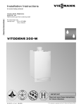
Installation and service
instructions
VIESMANN
for contractors
Vitotronic 100
Type HC1B
Digital boiler control unit
Vitotronic 300-K
Type MW2B
Weather-compensated, digital cascade control unit
For applicability, see the last page
VITOTRONIC 100
VITOTRONIC 300-K
5601 090 GB
7/2011
Please keep safe.
Safety instructions
Safety instructions
Please follow these safety instructions closely to prevent accidents and material losses.
Safety instructions explained
Danger
This symbol warns against the
risk of injury.
!
Please note
This symbol warns against the
risk of material losses and environmental pollution.
Note
Details identified by the word "Note" contain additional information.
■ all current safety regulations as
defined by DIN, EN, DVGW, TRGI,
TRF, VDE and all locally applicable
standards,
■ Gas Safety (Installation & Use) Regulations
– the appropriate Building Regulation
either the Building regulations, the
Building Regulation (Scotland),
Building Regulations (Northern Ireland),
– the Water Fittings Regulation or
Water Bylaws in Scotland,
– the current I.E.E. Wiring Regulations.
Target group
If you smell gas
Regulations
Observe the following when working on
this system
■ all legal instructions regarding the prevention of accidents,
■ all legal instructions regarding environmental protection,
■ the Code of Practice of relevant trade
associations,
2
Danger
Escaping gas can lead to explosions which may result in serious
injury.
■ Never smoke. Prevent naked
flames and sparks. Never
switch lights or electrical appliances ON or OFF.
■ Close the gas shut-off valve.
■ Open windows and doors.
■ Remove all people from the
danger zone.
■ Notify your gas or electricity
supplier from outside the building.
■ Shut off the electricity supply to
the building from a safe place
(outside the building).
5601 090 GB
These instructions are exclusively
designed for qualified personnel.
■ Work on gas equipment must only be
carried out by a qualified gas fitter.
■ Work on electrical equipment must
only be carried out by a qualified electrician.
■ The system must be commissioned by
the system installer or a qualified person authorised by the installer.
Safety instructions
Safety instructions (cont.)
If you smell flue gas
Danger
Flue gas can lead to life-threatening poisoning.
■ Shut down the heating system.
■ Ventilate the boiler room.
■ Close all doors leading to the
living space.
Working on the system
■ When using gas as fuel, also close the
main gas shut-off valve and safeguard
against unauthorised reopening.
■ Isolate the system from the power supply and check that it is no longer 'live',
e.g. by removing a separate fuse or by
means of a main isolator.
■ Safeguard the system against unauthorised reconnection.
!
Ancillary components, spare and
wearing parts
!
Please note
Spare and wearing parts which
have not been tested together
with the heating system can compromise its function. Installing
non-authorised components and
non-approved modifications/conversion can compromise safety
and may invalidate our warranty.
For replacements, use only original spare parts from Viessmann
or those which are approved by
Viessmann.
Please note
Electronic modules can be damaged by electro-static discharges.
Touch earthed objects, such as
heating or water pipes, to discharge static loads.
Repair work
Please note
Repairing components which fulfil a safety function can compromise the safe operation of your
heating system.
Replace faulty components only
with original Viessmann spare
parts.
5601 090 GB
!
3
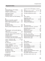
Index
Index
Installation instructions
Preparing for installation
System version ID: 4605016................................................................................
7
Installation, Vitotronic 100
Installation information for the Vitotronic 100....................................................... 10
Installing a cascade communication module........................................................ 10
Installation, Vitotronic 300-K
Overview of electrical connections on the Vitotronic 300-K.................................
Installing the mounting bracket and control unit back..........................................
Installing a PCB, extension for heating circuits 2 and 3.......................................
Inserting cables/leads and applying strain relief...................................................
Making the connections to the Vitotronic 100.......................................................
Connecting sensors..............................................................................................
Connecting pumps...............................................................................................
Connecting servomotors......................................................................................
Connecting the central fault message facility.......................................................
External demand via switching contact................................................................
External demand via 0 – 10 V input.....................................................................
External blocking via switching contact................................................................
External "Mixer close"/"Mixer open".....................................................................
External heating program changeover.................................................................
Making the LON connection.................................................................................
Power supply........................................................................................................
Fitting the control unit front...................................................................................
Opening the control unit.......................................................................................
13
15
16
16
17
18
19
21
22
23
24
24
25
26
28
30
32
33
Service instructions
34
34
34
35
35
39
39
41
Service scans, Vitotronic 100
Calling up the service level................................................................................... 44
Exiting the service level........................................................................................ 44
4
5601 090 GB
Commissioning
Changing the language........................................................................................
Setting the date and time.....................................................................................
Matching coding addresses to the system version...............................................
Selecting the boiler sequence (if required)...........................................................
Connecting the control unit to the LON system....................................................
Testing actuators on the Vitotronic 100................................................................
Testing actuators and sensors on the Vitotronic 300-K........................................
Adjusting the heating curve..................................................................................
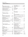
Index
Index
Scanning operating data...................................................................................... 44
Brief scan............................................................................................................. 44
Service scans, Vitotronic 300-K
Calling up the service menu.................................................................................
Exiting the service menu......................................................................................
Scanning operating data......................................................................................
Brief scan.............................................................................................................
47
47
47
48
Troubleshooting, Vitotronic 300-K
Fault display......................................................................................................... 51
Fault codes........................................................................................................... 52
Function description, Vitotronic 100 and Vitotronic 300-K
Boiler water temperature control of the Vitotronic 100.........................................
Cascade control of the Vitotronic 300-K...............................................................
Heating circuit control unit of the Vitotronic 300-K...............................................
Cylinder temperature control................................................................................
62
62
68
77
Code 1, Vitotronic 300-K
Calling up coding level 1......................................................................................
"General" group....................................................................................................
"Cascade" group..................................................................................................
"DHW" group........................................................................................................
"Solar" group........................................................................................................
"Heating circuit 1", "Heating circuit 2", "Heating circuit 3" group..........................
81
81
83
84
85
87
Code 2, Vitotronic 300-K
Calling up coding level 2...................................................................................... 92
"General" group.................................................................................................... 92
"Cascade" group.................................................................................................. 102
"DHW" group........................................................................................................ 105
"Solar" group........................................................................................................ 108
"Heating circuit 1", "Heating circuit 2", "Heating circuit 3" group.......................... 114
Schemes, Vitotronic 100
Connection and wiring diagrams.......................................................................... 123
5601 090 GB
Schemes, Vitotronic 300-K
Connection and wiring diagrams.......................................................................... 124
Components
Sensors................................................................................................................ 129
5
Index
Index (cont.)
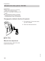
Radio clock receiver, part no. 7450 563............................................................... 130
Extension kit, mixer, part no. 7441 998................................................................ 132
Mixer motor, part no. 9522 487............................................................................ 133
Mixer motor, part no. Z004 344............................................................................ 134
Temperature limiter for limiting the maximum temperature.................................. 136
Extension EA1, part no. 7452 091........................................................................ 137
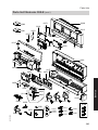
Parts lists
Parts list Vitotronic 100......................................................................................... 140
Parts list Vitotronic 300-K..................................................................................... 140
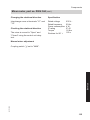
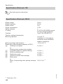
Specification
Specification Vitotronic 100.................................................................................. 142
Specification Vitotronic 300-K.............................................................................. 142
5601 090 GB
Keyword index.................................................................................................... 143
6
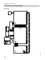
Preparing for installation
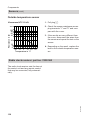
System version ID: 4605016
Multi boiler system with several heating circuits with mixer and
low loss header (with/without DHW heating)
Hydraulic installation scheme
43
--6/2-44
--6/20-45
--6/52--
7
--6/28--
3
11
--6/5--
51
52
45
--6/52--
53
50
--230V---20--
2
4
4
--5---1---143---KM BUS---2--
--KM BUS--
5
1
6
--230V---21---28---50---20---52--
--KM BUS--
10
--5/20--
44
--6/20--
16
--230V---20--
KW
--6/21--
--2/20--
43
--6/2--
--6/2--
12
---
40
--6/1--
WW
42
--6/20--
Installation
40
5601 090 GB
Note: This scheme is a general example without shut-off devices or safety equipment. This does not replace the need for local engineering.
7
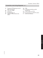
Preparing for installation
System version ID: 4605016 (cont.)
Equipment required
Pos.
1
2
5
3
4
6
7
qP
qQ
qW
qZ
rP
rW
rE
rR
5601 090 GB
rT
tP
tQ
tW
tE
Description
Multi boiler system with 2, 3 or 4 Vitodens 200-W, hydraulic cascade with
low loss header and connection accessories
with
Constant temperature control unit
Constant temperature control unit
Cascade communication module
Internal extension H1 (accessory)
Vitotronic 300-K
Outside temperature sensor ATS
DHW heating
DHW cylinder
Cylinder temperature sensor STS
DHW circulation pump ZP
Circulation pump for cylinder heating UPSB
Heating circuit with mixer
Temperature limiter to restrict the maximum temperature of underfloor heating systems
■ As immersion thermostat
or
■ As contact thermostat
Flow temperature sensor, heating circuit M2/M3
Heating circuit pump, heating circuit M2, M3
and
3-way mixer
Extension kit, mixer (mixer motor and flow temperature sensor rE)
Low loss header
Flow temperature sensor for low loss header
Boiler circuit pump
Boiler circuit pump
8
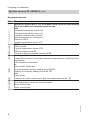
Preparing for installation
System version ID: 4605016 (cont.)
Required codes
Vitotronic 100 (set codes at every Vitotronic 100)
Group
Code
2
01:2
Multi boiler system with Vitotronic 300-K
Note
Code "00:0" is set automatically.
07:1
07:2
07:3
07:4
07:...
Vitotronic 300-K
Group
Code
"General"
00:...
"General"
"Cascade"
7E:1
35:1
35:2
35:3
35:4
35:...
Setting the boiler number at the Vitotronic 100 of the
respective boiler
Boiler 1 (delivered condition)
Boiler 2
Boiler 3
Boiler 4
Boiler ...
Installation
2
System version, see table for coding address 00 in the
overview on page 81.
With positive pressure flue gas cascade.
Never adjust.
Multi boiler system with two boilers
Multi boiler system with three boilers
Multi boiler system with four boilers (delivered condition)
Multi boiler system with ... boilers
5601 090 GB
Vitotronic 200-H (if installed)
Group
Code
"General"
97:1
The outside temperature is accepted by the LON BUS.
9
Installation, Vitotronic 100
Installation information for the Vitotronic 100
For installation, commissioning,
maintenance and service of
Vitodens 200-W with
Vitotronic 100: see separate
installation instructions and service instructions.
If a DHW cylinder is to be integrated into
the system, make the connection at the
Vitotronic 300-K (or, if installed, at the
Vitotronic 200-H).
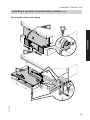
Installing a cascade communication module
5601 090 GB
The communication module is part of the
standard delivery.
10
Installation, Vitotronic 100
Installing a cascade communication module (cont.)
Opening the control unit casing
2. 2x
Installation
3.
1.
5.
5601 090 GB
4. 8x
11
Installation, Vitotronic 100
Installing a cascade communication module (cont.)
Installation of the communication module
7.
5601 090 GB
6.
12
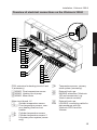
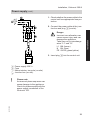
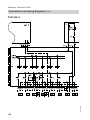
Installation, Vitotronic 300-K
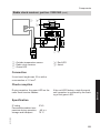
Overview of electrical connections on the Vitotronic 300-K
52
52
20
20
2
2
M3
M2
M3
M2
M3
M2
145
145
1
3/2
5 A
5 B
17 B
143
146
5601 090 GB
Installation
LON
28
21
52 A1
20 A1
29
50
40
156
PCB, extension for heating circuits 2 and
3 (accessory)
? M2/M3 Flow temperature sensor
sÖ M2/M3 Heating circuit pump
gS M2/M3 Mixer motor
aJB
Main circuit board, LV
Outside temperature sensor
!
§/? Flow temperature sensor, common heating flow/low loss
header
Cylinder temperature sensor
%A
Cylinder temperature sensor 2
%B
for primary store system (accessory)
aVH
LON
aVD
aVG
Temperature sensor, primary
store system (accessory)
External hook-ups
KM BUS subscriber (Vitotronic
100 and accessories, e.g.
Vitotrol remote controls)
External hook-ups
LON BUS, connecting cable for
data exchange with the
Vitotronic 200-H and the
Vitocom
13
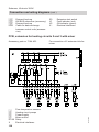
Installation, Vitotronic 300-K
Overview of electrical connections on the… (cont.)
■ When connecting external switching
contacts or components to the safety
LV of the control unit (aVD and aVH),
observe the requirements of safety
category II, i.e. 8.0 mm air and creep
path or 2.0 mm insulation thickness
from 'live' components.
■ For all on-site components (incl. PC/
laptops), ensure safe electrical separation to EN 60 335 or IEC 65.
■ When connecting plugs, sA, sK,sÖ
M2/M3, ? M2/M3, aVD and aVH,
bundle the individual wires of the
cables closely to the terminals.
This ensures that, in case of failure, for
example when a wire becomes
detached, the wires cannot drift into
the adjacent voltage area.
5601 090 GB
Main PCB 230 V~
sÖA1 Heating circuit pump
or
Primary pump, primary store system
Circulation pump for cylinder
sA
heating (accessory)
DHW circulation pump (on site)
sK
Distribution pump
sL
Power supply
fÖ
Central fault message
gÖ
gSA1 Motor for 3-way mixing valve, primary store system
aBH Internal power supply for mixer
extension PCB
14
Installation, Vitotronic 300-K
Installing the mounting bracket and control unit back
Installation
3.
2.
5601 090 GB
1.
15
Installation, Vitotronic 300-K
Installing a PCB, extension for heating circuits 2 and 3
Accessory, part no. 7164 403
Separate installation instructions
Inserting cables/leads and applying strain relief
A
D
C
D
B
C Plug-in connection diagram
D Fem. mouldings for plug-in connection diagram
5601 090 GB
A Cables with moulded strain relief
B On-site cables; strip up to 100 mm
insulation.
16
Installation, Vitotronic 300-K
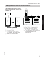
Making the connections to the Vitotronic 100
The cascade communication module
must be fitted into every Vitotronic 100
(see page 10).
A
145
A
B
C
C
1 2 3 4
1 2 3 4
KMK1 KMK2
D
A Plug aVG for Vitotronic 300-K
B 2-core cable (cross-section
2 x 0.5 mm2, total length 50 m)
D Terminal strip on the cascade communication module in the
Vitotronic 100
5601 090 GB
A Vitotronic 300-K
B 2-core cable (cross-section
2 x 0.5 mm2, total length 50 m)
C Boiler with Vitotronic 100
B
KMK1 KMK2
D
B
B
Installation
2 1
B
17
Installation, Vitotronic 300-K
Connecting sensors
1
2 1 2 1
3 2 1
2 1
2 1 2 1
2 1
145 145
1
3/2
5A 5B
17B
Outside temperature sensor
!
§/? Flow temperature sensor common flow/low loss header
Cylinder temperature sensor 1
%A
Cylinder temperature sensor 2
%B
for primary store system (accessory)
aJB
Temperature sensor, primary
store system (accessory)
Installation point for outside temperature sensor
■ North or north-western wall, 2 to
2.5 m above ground level; in multistorey buildings, in the upper half of
the second floor
■ Not above windows, doors or ventilation outlets
■ Not immediately below balconies or
gutters
■ Never render over
Outside temperature sensor connection
5601 090 GB
2-core lead, up to 35 m long with a crosssection of 1.5 mm2
18
Installation, Vitotronic 300-K
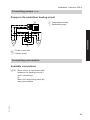
Connecting pumps
Available pump connections
Installation
sÖA1 Heating circuit pump
or
Primary pump, primary store system
Circulation pump for cylinder
sA
heating
DHW circulation pump
sK
Distribution pump
sL
Pumps 230 V~
M A
1~
Rated current
4(2) A~
Recommended
connecting cable H05VV-F3G
0.75 mm2
or
H05RN-F3G
0.75 mm2
B
5601 090 GB
A Pump
B To the control unit
19
Installation, Vitotronic 300-K
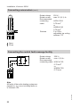
Connecting pumps (cont.)
Pumps with power consumption greater than 2 A
N
L
D
L N
L
C
N
External
ON/OFF
B
A Pump
B To the control unit
C Contactor
L N PE
A
D Separate power connection
(observe manufacturer's details)
Pumps 400 V~
N
L
L1 L2 L3 N PE
For switching the contactor
Rated current
4(2) A~
Recommended
connecting cable H05VV-F3G
0.75 mm2
or
H05RN-F3G
0.75 mm2
C
B
M
A 3~
5601 090 GB
A Pump
B To the control unit
C Contactor
20
Installation, Vitotronic 300-K
Connecting pumps (cont.)
Pumps in the underfloor heating circuit
B Temperature limiter
C Secondary pump
sÖ
N
20
L
A
M
1~
B
Installation
M
1~
C
sÖ To the control unit
A Primary pump
Connecting servomotors
Available connections
5601 090 GB
gS A1 Mixer motor, in conjunction with
extension for heating circuits 2
and 3 (accessory)
or
Motor for 3-way mixing valve, primary store system
21
Installation, Vitotronic 300-K
Connecting servomotors (cont.)
Rated voltage
Rated current
Recommended
connecting
cable
M
1~
52
Runtime
230 V~
max. 0.2 (0.1) A~
H05VV-F4G
0.75 mm2
or
H05RN-F4G
0.75 mm2
5 to 199 s,
adjustable via coding
address "C3"
Open
Close
Connecting the central fault message facility
L
N
Rated voltage
230 V~
Rated current
max. 4 (2) A~
Recommended
connecting cable H05VV-F3G
0.75 mm2
or
H05RN-F3G
0.75 mm2
50
5601 090 GB
Note
All faults of the entire heating system are
passed on, e.g. even including faults on
a Vitotronic 100.
22
Installation, Vitotronic 300-K
External demand via switching contact
Connection options:
■ Plug aVH
■ Extension EA1 (accessory, see
page 137)
Connection
!
Plug aVH
A
Installation
Please note
'Live' contacts lead to short circuits or phase failure.
The external connection must be
potential-free.
Extension EA1
DE
[{A
DE
[{S
B
DE
[{D
1 2 3
146
B
A Floating contact
B Plug aVH on control unit
A
A Floating contact
B Extension EA1
With the contact closed, the boiler burners are started subject to load. They heat to
the additional set flow temperature selected in coding address "9b" in the "General" group. The temperature is limited by this set value and the electronic maximum
flow temperature limit (coding address "37" in the "Cascade" group).
Codes
Extension EA1
Set "5d", "5E" or "5F" in the "General" group
to 2.
5601 090 GB
Plug aVH
No code required.
23
Installation, Vitotronic 300-K
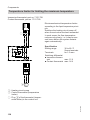
External demand via 0 – 10 V input
Connection at input 0 – 10 V to extension EA1 (see page 137).
Ensure DC separation between the negative pole and the earth conductor of the
on-site voltage source.
0-10V
[{{]
aBJ
12
SÖ P
A
f-]
0 - 1 V ≙ No default set flow temperature
1V
≙ Set value 10 °C
10 V
≙ Set value 100 °C
Observe coding address "1E" in the
"General" group.
fÖ
L?N N?L
230 V~
= 0-10 V
+
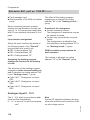
External blocking via switching contact
Connection options:
■ Plug aVD
■ Extension EA1 (accessory, see
page 137)
Connection
Please note
'Live' contacts lead to short circuits or phase failure.
The external connection must be
potential-free.
5601 090 GB
!
24
Installation, Vitotronic 300-K
External blocking via switching contact (cont.)
Plug aVD
A
Extension EA1
DE
[{A
DE
[{S
B
DE
[{D
1 2 3
143
A Floating contact
B Plug aVD on control unit
Installation
A
B
A Floating contact
B Extension EA1
With the contact closed, the burners of all boilers will be subject to a controlled
shutdown. The boiler circuit pumps are switched off.
!
Please note
During the block, there is no frost
protection
of the heating system.
Codes
Plug aVD
Set coding address "99" in the
"General" group.
Extension EA1
Set "5d", "5E" or "5F" in the "General" group
to 3 or 4.
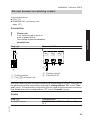
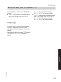
External "Mixer close"/"Mixer open"
5601 090 GB
Connection at plug aVD
25
Installation, Vitotronic 300-K
External "Mixer close"/"Mixer open" (cont.)
A
!
Please note
'Live' contacts lead to short circuits or phase failure.
The external connection must be
floating.
B
1 2 3
143
A External "Mixer open"
(floating contact)
B External "Mixer closed"
(floating contact)
Codes
External "Mixer open"
This function is assigned to the heating
circuits via coding address "9A" in the
"General" group.
External "Mixer closed"
This function is assigned to the heating
circuits via coding address "99" in the
"General" group.
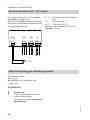
External heating program changeover
Optional connections:
■ Plug aVD
■ Extension EA1 (accessory, see chapter "Components")
!
26
Please note
'Live' contacts lead to short circuits or phase failure.
The external connection must be
floating.
5601 090 GB
Connection
Installation, Vitotronic 300-K
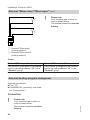
External heating program changeover (cont.)
Plug aVD
A
Extension EA1
The changeover can be achieved separately for
heating circuits 1 to 3.
B
DE1
DE3
DE2
1 2 3
143
A Floating contact
B Plug aVD of the control
unit
A
A
A
Installation
B
A Floating contact
B Extension EA1
Changed heating program
(Contact closed)
Constant operation with reduced
room temperature/DHW heating
OFF
Constant operation with standard
room temperature, DHW heating
in accordance with coding
address "64" in the "DHW"
group
5601 090 GB
Preselected heating program
Code
(Contact open)
Central heating OFF/ "d5:0" in the
DHW OFF
"Heating
circuit ..."grou
p
(Delivered
condition)
or
Central heating OFF/ "d5:1" in the
DHW heating ON
"Heating
circuit ..."grou
p
or
Central heating ON/
DHW heating ON
27
Installation, Vitotronic 300-K
External heating program changeover (cont.)
Codes
Plug aVD
Via coding address "91" in the
"General" group, the function
can be assigned to the heating
circuits.
Extension EA1
Set "5d", "5E" or "5F" in the "General" group to
1.
Via coding address "d8" in the "Heating circuit..." group, the function can be assigned to the
heating circuits.
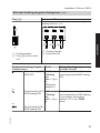
Making the LON connection
The Viessmann LON system is designed
for the "Line" BUS topology with a terminator at both ends (accessories). For
free wiring with a central terminator (BUS
terminator), please see the "Viessmann
LON manual" at www.viessmann.de/
lon.
The transfer distances for LON are subject to the electrical properties of the
respective cabling. For this reason, only
use the stated cable types. Use only one
type of cable within the LON.
Cable types (on site):
■ 2-core cable, CAT 5, screened
■ JY(St)Y 2 x 2 x 0.8 mm (telephone
cable)
Observe the cabling requirements for the
operation of the LON interface FTT 10-A
(see www.echelon.com).
All Viessmann equipment is connected
via RJ45 plugs. The Viessmann LON
system always requires the cores "1"
and "2" and the screen. The cores are
interchangeable. The installation is
therefore safe from pole errors.
Note
When connecting equipment and during
wiring, observe the requirements of protection class II, i.e. 8.0 mm air-gap and
creep path or maintain a 2.0 mm insulation thickness against live parts.
Ensure a safe electrical separation for all
on-site components (incl. PC/laptops) to
ensure conformity to EN 60 335 or IEC
65.
Connection with Viessmann LON cable
A
A
A
C
C
B
The line may be up to ≤ 7 m long
28
5601 090 GB
B
Installation, Vitotronic 300-K
Making the LON connection (cont.)
A Control unit or Vitocom
B LON cable, 7 m long
C Terminator
Connection with Viessmann LON cable and coupling
A
A
A
C
C
B D B
B D
B D B
Installation
B D
Installation spacing 7 to 21 m
A Control unit or Vitocom
B LON cable, 7 m long
Max. 3 cables between 2 appliances
C Terminator
D LON coupling
Connection with on-site cable and LON plug
A
A
D
D
E
D
A
D
C
C
B
B
≤ 900 m
The line may be up to ≤ 900 m (with LON plug)
D LON plug
E Up to 99 subscribers
5601 090 GB
A Control unit or Vitocom
B On-site cable
C Terminator
29
Installation, Vitotronic 300-K
Making the LON connection (cont.)
Connection with LON cable, on-site cable and LON junction box
A
D
C
F
A
D
D
B
D
C
B
E
A
B
≤ 900 m
B
E
The line may be up to ≤ 900 m (with LON junction boxes)
A Control unit or Vitocom
B LON cable, 7 m long
C Terminator
D LON junction boxes
E On-site cable
F Up to 99 subscribers
Power supply
Directives
Carry out the power supply connection
and all earthing measures (i.e. RCD circuit) in accordance with IEC 60364, the
requirements of your local power supply
utility, and VDE or national regulations.
Protect the power cable to the control
unit with an appropriate fuse/MCB.
For oil and gas combustion equipment
over 100 kW, according to the Sample
Combustion Ordinance "FeuVO", an
"emergency shutdown" must be installed
on site outside the installation room. The
national combustion equipment ordinance for your local region must be
observed. For combustion equipment to
EN 50156-1, the "emergency shutdown" installed on site must comply with
the requirements of EN 50156-1.
30
Install the "emergency shutdown" outside the installation room; it must be able
to separate all non-earthed conductors
simultaneously with a gap of 3 mm at
least.
We additionally recommend installing an
AC/DC-sensitive RCD (RCD class B
) for DC (fault) currents that can occur
with energy-efficient equipment.
Recommended power cable
3-core cable selected from the following
options:
■ H05VV-F3G 1.5 mm2
■ H05RN-F3G 1.5 mm2
5601 090 GB
Regulations
Installation, Vitotronic 300-K
Power supply (cont.)
1. Check whether the power cable to the
control unit has appropriate fuse protection.
L1
PE
N
N
L
40
A
B
C
D
3. Insert plug fÖ into the control unit.
Power supply 230 V~
Fuse
Mains isolator, two-pole (on-site)
Junction box (on site)
Please note
An incorrect phase sequence can
cause damage to the appliance.
Check for phase equality with the
power supply connection of the
Vitotronic 100.
5601 090 GB
!
Danger
Incorrect core allocation can
cause severe injury and can
damage the appliance.
Take care not to interchange
wires "L1" and "N":
L1 BN (brown)
N BU (blue)
PE GNYE (green/yellow)
31
Installation
BU
GNYE
BN
2. Connect the power cable at the junction box and plug fÖ (on-site).
Installation, Vitotronic 300-K
Fitting the control unit front
3.
2.
A
1.
7.
5.
4.
6.
5601 090 GB
8.
32
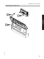
Installation, Vitotronic 300-K
Opening the control unit
1.
Installation
2.
5601 090 GB
3.
33
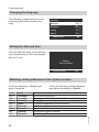
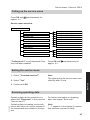
Commissioning
Changing the language
The following is displayed during commissioning (delivered condition German).
Sprache
Deutsch
ç
DE ê
Bulgarski
BG ê
Cesky
CZ ê
Dansk
DK ê
Wählen mit
(
Setting the date and time
The time and date need to be reset during commissioning or after a prolonged
time out of use.
Setting
Time and date
Continue with
OK
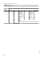
Matching coding addresses to the system version
Check all addresses in Code 1 and
adjust if required.
Group
"Cascade"
"Cascade"
"General"
"DHW"
"General"
"General"
"General"
"General"
Function
Permanent lead boiler
Permanent last boiler
Plug sÖ function
Cylinder temperature control function
LON subscriber number
Central control
Viessmann system number
Monitoring LON subscribers
5601 090 GB
"39"
"3A"
"4C"
"55"
"77"
"7A"
"98"
"9C"
Check the following coding addresses
and adjust accordingly in Code 2:
34
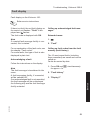
Commissioning
Selecting the boiler sequence (if required)
Subject to the codes set in the "Cascade" group and internal control calculations, the control unit offers various
boiler sequences. Coding addresses
that influence the boiler sequence:
"38"
Changing the lead boiler
and the boiler sequence
"39"
Permanent lead boiler
"3A"
Permanent last boiler
"41" to "44" ECO thresholds
"65", "6F" ECO thresholds
"74", "7d" ECO thresholds
■ Via the ECO threshold, every boiler
can be blocked or enabled subject to
the outside temperature.
■ The ECO threshold is disabled if the
boiler is required to achieve the set
flow temperature in the case of enabled boilers failing.
■ At least the lead boiler remains in
operation when all boilers in a system
would otherwise be blocked via the
ECO threshold.
1. Press å.
2. "Boiler sequence"
3. Select the required boiler sequence
and confirm with "OK".
■ Vitotronic 300-K and 200-H:
The LON communication module
(accessory) must be fitted.
Installation and service instructions, Vitotronic 200-H
■ Within one LON, the system number
(coding address "98" in the "General" group) must always be the same.
■ Only one Vitotronic may be programmed as fault manager.
■ The data transfer via LON can take
several minutes.
5601 090 GB
■ Within one LON, the same subscriber
number must not be allocated twice.
35
Service
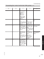
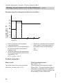
Connecting the control unit to the LON system
Commissioning
Connecting the control unit to the LON system (cont.)
Example of a multi boiler system
A Vitotronic 100
B Vitotronic 100
C Vitotronic 300-K
A
LON
E
LON
LON
D
D Vitotronic 200-H
E Vitocom
F LON
B
C
D
E
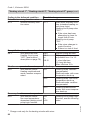
Multi boiler sys- —
tem.
Set code "01:2"
in group 2
"Boiler".
—
—
Boiler number 2 —
to ...
Set code "07:2
to ..." in group 2
"Boiler".
—
—
With cascade
communication
module.
Code "76:2" in
group 1 "General"; automatic
recognition.
With LON
—
communication module.
Code "76:1" in
the "General"
group; automatic recognition.
With LON
communication module.
Code "76:1" in
the "General"
group; automatic recognition.
5601 090 GB
Multi boiler system.
Set code
"01:2" in
group 2
"Boiler".
Boiler number
1.
Code "07:1" in
group 2
"Boiler" (delivered condition).
With cascade
communication
module.
Code "76:2" in
group 1 "General"; automatic recognition.
C
LON
145
B
KMK1
KMK2
A
KMK2
F
36
Commissioning
Connecting the control unit to the LON system (cont.)
B
—
—
—
—
—
—
—
—
—
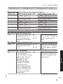
Number of
connected
boilers.
Set codes
"35:1" to
"35:8" in the
"Cascade"
group.
Subscriber no.
5.
Code "77:5" in
the "General"
group.
Control unit is
fault manager
Code "79:1" in
the "General"
group.
D
—
Subscriber no.
10.
Code "77:10"
in the "General" group.
Control unit is
not fault manager
Code "79:0" in
the "General"
group.
Control unit
Control unit
transmits the
receives the
time
time
Code "7b:1" in Set code
the "General" "81:3" in the
group.
"General"
group.
Flue gas cas- —
cade with positive pressure.
Set code "7E:
1" in the "General" group.
E
—
Subscriber no.
99.
Device is fault
manager.
Device
receives the
time.
—
5601 090 GB
—
C
Service
A
37
Commissioning
Connecting the control unit to the LON system (cont.)
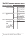
A
B
—
—
—
—
C
D
E
Control unit
transmits outside temperature
Code "97:2" in
the "General"
group.
Control unit
—
receives outside temperature
Set code
"97:1" in the
"General"
group.
LON subLON sub—
scriber remote scriber remote
monitoring.
monitoring.
Code "9C:20" Code "9C:20"
in the "Genin the "General" group.
eral" group.
Carrying out the LON subscriber check
The subscriber check is used to test
communication with the system devices
connected to the fault manager.
Preconditions:
■ The control unit must be programmed
as fault manager (code "79:1").
■ The LON subscriber number must be
programmed in all control units.
■ The LON subscriber list in the fault
manager must be up to date.
Carry out subscriber check:
1. Press OK and å simultaneously
for approx. 4 s.
2. "Service functions"
Note
To carry out a new subscriber check,
create a new subscriber list with "Delete
list?" (subscriber list is updated).
Information regarding Vitotronic 200H
During the subscriber check, the display
for the relevant subscriber shows the
subscriber no. and "Wink" for approx.
1 min.
5601 090 GB
3. "Subscriber check"
4. Select subscriber (e.g. subscriber
10).
The subscriber check for the selected
subscriber is initiated.
■ Successfully tested subscribers
are designated with "OK".
■ Unsuccessfully tested subscribers
are designated with "Not OK".
38
Commissioning
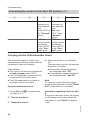
Testing actuators on the Vitotronic 100
Carrying out relay test
1. Press OK and å simultaneously
for approx. 4 s.
Ü flashes on the display.
4. Confirm selected actuator with OK.
The display shows the number for the
activated actuator and "ON".
2. Select
5. Exit the service level (see
page 44).
"
" and confirm with OK.
3. Select required actuator (output) with
/ (see the following table).
The following actuators can be switched subject to system equipment level:
Display
Explanation
0
All actuators have been switched off.
1
Burner operates at min. output.
2
Burner operates at max. output.
3
Internal output sÖ is enabled.
Testing actuators and sensors on the Vitotronic 300-K
Carrying out relay test
5601 090 GB
2. "Actuator test"
The following actuators can be switched subject to system equipment level:
Display
Explanation
"All actuators"
OFF
All actuators have been switched off.
"Output 20"
ON
Output 20 active.
"Output 52"
Open
"Output 52"
Neutral
"Output 52"
Close
"Cylinder prim pump"
ON
Output circulation pump for cylinder heating
active.
"DHW circ pump"
ON
Output DHW circulation pump active.
"Output 29"
ON
Output 29 active.
"Central fault message" ON
"Htg circ pump HC2"
ON
Heating circuit pump output active (heating
circuit with mixer M2).
39
Service
1. Press OK and å simultaneously
for approx. 4 s.
Commissioning
Testing actuators and sensors on the Vitotronic… (cont.)
Display
"Mixer HC2"
Open
"Mixer HC2"
Close
"Htg circ pump HC3"
ON
"Mixer HC3"
Open
"Mixer HC3"
Close
"EA1 output 1"
ON
"AM1 output 1"
"AM1 output 2"
"Solar circuit pump"
ON
ON
ON
"Solar circ pmp min"
ON
"Solar circ pmp max"
ON
"SM1 output 22"
ON
Explanation
Output "Mixer open" active (heating circuit
with mixer M2).
Output "Mixer close" active (heating circuit
with mixer M2).
Output heating circuit pump active (heating
circuit with mixer M3).
Output "Mixer open" active (heating circuit
with mixer M3).
Output "Mixer close" active (heating circuit
with mixer M3).
Contact "P - S" on plug aBJ of extension EA1
closed.
Output 1 active.
Output 2 active.
Output for solar circuit pump sF at solar control module , type SM1 active.
Output for solar circuit pump sF at solar control module, type SM1, switched to minimum
speed.
Output for solar circuit pump sF at solar control module, type SM1, switched to maximum
speed.
Output sS on solar control module, type SM1
active.
Information regarding the mixer
motor rotational direction
The flow temperature must rise when the
mixer opens. If the temperature drops,
either the motor is turning in the wrong
direction or the mixer set is incorrectly
fitted (observe the mixer installation
instructions).
Checking sensors
1. Press OK and
approx. 4 s.
simultaneously for
2. "Diagnosis"
5601 090 GB
3. Select group (see page 47).
40
Commissioning
Testing actuators and sensors on the Vitotronic… (cont.)
4. Scan actual temperature of the relevant sensor.
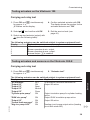
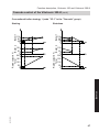
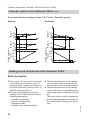
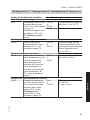
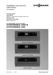
Adjusting the heating curve
The heating curves illustrate the relationship between the outside temperature
and the boiler water or flow temperature.
To put it simply: The lower the outside
temperature, the higher the boiler water
or flow temperature.
The room temperature, in turn, depends
on the boiler water or flow temperature.
Note
If the heating system includes heating
circuits with mixers, then the flow temperature of the heating circuit without
mixer is higher by a selected differential
(8 K in the delivered condition) than the
flow temperature of the heating circuits
with mixers.
The differential temperature is adjustable via coding address "9F" in the "General" group.
80
70
60
50
40
1.6
1.8
2.0
2.8
2.6
2.4
2.2
3.0
1.4
1.2
1.0
0.8
0.6
0.4
0.2
0 -5 -10 -15 -20 -25 -30
Outside temperature in °C
5601 090 GB
30
3
Se 0 2
t ro
5
om
10 5
tem 20
per 15
atu
1
re
in ° 0 5
C
Slope
Service
35
Boiler water or
Flow temperature in °C
90
3.4
3.2
Settings in the delivered condition:
■ Slope = 1.4
■ Level = 0
41
Commissioning
Adjusting the heating curve (cont.)
Slope setting ranges:
■ Underfloor heating systems: 0.2 to 0.8
■ Low temperature heating systems: 0.8
to 1.6
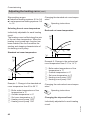
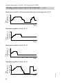
Changing the standard set room temperature
Operating instructions
Selecting the set room temperature
Reduced set room temperature
Individually adjustable for each heating
circuit.
The heating curve is offset along the axis
of the set room temperature. When the
heating circuit pump logic function has
been enabled, the curve modifies the
starting and stopping characteristics of
the heating circuit pump.
90
A
C
Standard set room temperature
D
90
A
C 26
D
+2
+2
0
14
5
B -20
E
Example 2: Change in the reduced set
room temperature from 5 °C to 14 °C
0
B -20
E
Example 1: Change in the standard set
room temperature from 20 to 26 °C
Changing the reduced set room temperature
Operating instructions
Changing the slope and level
Individually adjustable for each heating
circuit.
5601 090 GB
A Boiler water temperature or flow
temperature in °C
B Outside temperature in °C
C Set room temperature in °C
D Heating circuit pump "OFF"
E Heating circuit pump "ON"
A Boiler water temperature or flow
temperature in °C
B Outside temperature in °C
C Set room temperature in °C
D Heating circuit pump "OFF"
E Heating circuit pump "ON"
42
Commissioning
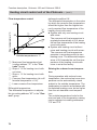
Adjusting the heating curve (cont.)
Boiler water or
flow temperature in °C
90
3.5
1.4
A
B
0.2
+20
-20
Outside temperature in °C
A Changing the slope
B Changing the level (vertical parallel
offset of the heating curve)
Extended menu:
1. å
2. "Heating"
3. Select heating circuit.
4. "Heating curve"
Service
5. "Slope" or "Level"
5601 090 GB
6. Select heating curve according to the
system requirements.
43
Service scans, Vitotronic 100
Calling up the service level
1. Press OK and
simultaneously for
approx. 4 s.
flashes on the display.
2. Select required function, e.g. relay
test.
Exiting the service level
1. Press
to select 7.
2. Confirm with OK.
"OFF" flashes.
3. Confirm with OK.
Note
The system exits the service level
automatically after 30 min.
Scanning operating data
Operating data can be scanned in the
"i" menu.
Operating instructions
Brief scan
3. Select the required scan with / . For
example, "b" for "Boiler coding card"
(see following table).
2. Confirm with OK.
4. Confirm selected scan with OK.
5601 090 GB
1. Press OK and
simultaneously for
approx. 4 s.
flashes on the display.
44
Service scans, Vitotronic 100
Brief scan (cont.)
For explanations of individual scans, see the following table:
Brief scan
Display
System
scheme
1
3
A
4
b
C
c
d
Output 28
configuration (value
corresponds to
setting in
coding
address
"53" in
group 1
"General")
Software
version
Programming unit
Software version
Software
Burner control unit
version
Cascade
communication module
Set boiler water temperature
Common demand temperature
Burner control unit type
Appliance type
Max. heating output in %
Boiler coding card (hexadecimal)
Version
Version
Appliance
Burner control unit
Variable
Software
speed
version
pump
Variable
0 none
speed pump
1 Wilo
0: no varia2 Grundfos ble speed
pump
Internal details for calibration
5601 090 GB
F
1
Software version
Control unit
Service
0
45
Service scans, Vitotronic 100
Brief scan (cont.)
Brief scan
F
3
Output 157
configuration (value
corresponds to
setting in
coding
address
"36" in
group 1
"General")
Software
version
Output 157
switching
state
0: OFF
1: ON
Extension EA1
Input DE1
Input DE2
switching
switching
state
state
0: open
0: open
1: closed
1: closed
Input DE3
switching
state
0: open
1: closed
External hook-up 0 - 10 V
Display in %
5601 090 GB
F
4
Display
46
Service scans, Vitotronic 300-K
Calling up the service menu
Press OK and
approx. 4 s.
simultaneously for
Service menu overview
Service
Diagnosis
Actuator test
Coding level 1
Coding level 2
Fault history
Service functions
Terminate service?
"Coding level 2" is only displayed if this
level has been enabled:
General
Heating circuit 1
Heating circuit 2
Heating circuit 3
DHW
Solar
Brief scan
Reset data
HC1
HC2
HC3
Subscriber check
Service PIN
Vitocom PIN input
Service reset
Press OK and
approx. 4 s.
simultaneously for
Exiting the service menu
2. Select "Yes".
Note
The system exits the service menu automatically after 30 min.
Service
1. Select "Terminate service?".
3. Confirm with OK.
5601 090 GB
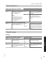
Scanning operating data
Operating data can be scanned in six
areas (see "Diagnosis" in the overview
"Service menu").
Operating data on heating circuits with
mixers and solar can only be scanned if
the components are installed in the system.
For further information on operating
data, see chapter "Brief scan".
Note
"- - -" appears on the display if a sensor
that has been scanned is faulty.
47
Service scans, Vitotronic 300-K
Scanning operating data (cont.)
Calling up operating data
1. Press OK and
approx. 4 s.
simultaneously for
3. Select required group, e.g. "General".
2. "Diagnosis"
Resetting operating data
Saved operating data (e.g. hours run)
can be reset to 0.
The value "Adjusted outside temp" is
reset to the actual value.
1. Press OK and
approx. 4 s.
simultaneously for
2. "Diagnosis"
3. "Reset data"
4. Select required value or "All
details".
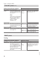
Brief scan
2. "Diagnosis"
3. "Brief scan".
simultaneously for
Diagnosis brief scan
1:
2:
3:
4:
0
0
0
0
1
0
0
0
0
0
0
0
A
A
0
0
Select with
0
0
0
0
A
1
0
0
For an explanation of the relevant values in the individual lines, see the following table:
Row (brief
Field
scan)
1
2
3
4
5
6
1:
System schemes 01 Control unit software
Programming unit
to 10
version
software version
2:
0
0
0
0
Device identification
ZE-ID
48
5601 090 GB
1. Press OK and
approx. 4 s.
4. Press OK.
The display shows 11 rows with 6
fields each.
Ø
In the brief scan, you can scan temperatures, software versions and connected
components, for example.
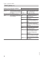
Service scans, Vitotronic 300-K
Brief scan (cont.)
Field
3:
0
1
0
3
4
Number of KM BUS
subscribers
4:
5:
0
0
0
0
0
0
6:
7:
0
0
Subnet address/system number
SNVT
Software
config.
version
0: Auto
Comm.
1: Tool
coproc.
Heating circuit HC1
Remote
Software
control
version
0:
Remote
none
control
1:
Vitotrol
200A
or
Vitotrol
200RF
2:
Vitotrol
300A
or
Vitohome
300
0
0
8:
9:
0
0
Node address
5
6
Software version
Solar control module,
type SM1
0
0
Software Software
version,
version,
extenextension AM1 sion EA1
0
0
0
0
Software version
Neuron chip
Number of LON subscribers
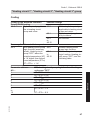
Heating circuit HC2
Remote
Software
control
version
0:
Remote
none
control
1:
Vitotrol
200A
or
Vitotrol
200RF
2:
Vitotrol
300A
or
Vitohome
300
0
0
Heating circuit HC3
Remote
Software
control
version
0:
Remote
none
control
1:
Vitotrol
200A
or
Vitotrol
200RF
2:
Vitotrol
300A
or
Vitohome
300
0
0
0
0
5601 090 GB
10:
2
49
Service
Row (brief
scan)
Service scans, Vitotronic 300-K
Brief scan (cont.)
Row (brief
scan)
Field
1
11:
0
2
0
3
Software
0
version,
extension
for heating
circuits 2
and 3 with
mixer
4
5
Software 0
version,
extension
for heating circuits 2
and 3 with
mixer
6
5601 090 GB
Note
The displays in fields 3 and 5 are the same.
50
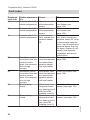
Troubleshooting, Vitotronic 300-K
Fault display
Fault display on the Vitotronic 100:
Boiler service instructions
If there is a fault, the red fault display on
the control unit flashes. "Fault" is displayed and flashes.
The fault code is displayed with OK.
Calling up acknowledged fault messages
Note
If a central fault message facility is connected, this is started.
1.
For an explanation of the fault code, see
the chapter "Fault codes".
For some faults, the type of fault is also
displayed in plain text.
Calling up fault codes from the fault
memory (fault history)
Acknowledging a fault
Extended menu:
2. "Fault"
The 10 most recent faults (including
those remedied) are saved and can be
called up.
Faults are sorted by date.
Follow the instructions on the display.
1. Press OK and å simultaneously
for approx. 4 s.
2. "Fault history"
Service
3. "Display?"
5601 090 GB
Note
The fault message is transferred to the
menu.
A fault messaging facility, if connected,
will be switched off.
If an acknowledged fault is not remedied,
the fault message will be re-displayed
the following day and the fault message
facility restarted.
51
Troubleshooting, Vitotronic 300-K
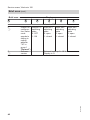
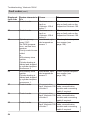
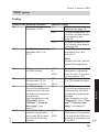
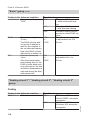
Fault codes
Displayed
fault code
10
18
19
20
28
40
Measures
Check outside temperature sensor (see
page 130).
Check outside temperature sensor (see
page 130)
Check wireless connection (place outside temperature sensor RF close
to the wireless base station). Log off outside temperature sensor then log
on again. Replace if necessary (see separate
installation and service
instructions).
Standalone control
Short circuit, com- Check the sensor (see
unit without flow tem- mon flow tempera- page 129).
perature sensor
ture sensor/tem(poss. flow tempera- perature sensor,
ture not high
low loss header
enough).
Standalone control
Lead break, com- Check the sensor (see
unit without flow tem- mon flow tempera- page 129).
perature sensor
ture sensor/tem(poss. flow tempera- perature sensor,
ture not high
low loss header
enough).
Mixer is being
Short circuit, flow
Check flow temperature
closed.
temperature sensensor (see page 129).
sor, heating circuit
with mixer M2
(heating circuit 2)
Mixer is being
Short circuit, flow
Check flow temperature
closed.
temperature sensensor (see page 129).
sor, heating circuit
with mixer M3
(heating circuit 3)
5601 090 GB
44
System characteris- Cause
tics
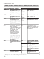
Activates after 0 °C
Short circuit, outoutside temperature. side temperature
sensor
Activates after 0 °C
Lead break, outoutside temperature. side temperature
sensor
Activates after 0 °C
Communication
outside temperature. fault, outside temperature sensor
RF
52
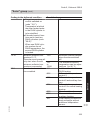
Troubleshooting, Vitotronic 300-K
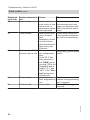
Fault codes (cont.)
4C
50
51
54
Measures
Check flow temperature
sensor (see page 129).
Check flow temperature
sensor (see page 129).
Check cylinder temperature sensor (see
page 129).
Check cylinder temperature sensor (see
page 129).
Check maintenance display or fault code on the
respective Vitotronic 100.
Check maintenance display or fault code on the
respective Vitotronic 100.
5601 090 GB
55
System characteris- Cause
tics
Mixer is being
Lead break, flow
closed.
temperature sensor, heating circuit
with mixer M2
(heating circuit 2)
Mixer is being
Lead break, flow
closed.
temperature sensor, heating circuit
with mixer M3
(heating circuit 3)
Cylinder primary
Short circuit, cylinpump "ON":
der temperature
Set DHW temperasensor 1
ture = set flow temperature
Priority control is cancelled.
or
With primary store
system:
Cylinder heating is
started and stopped
by cylinder temperature sensor 2.
With primary store
Short circuit, cylinsystem:
der temperature
Cylinder heating is
sensor 2
started and stopped
by cylinder temperature sensor 1.
Control mode.
Maintenance or
fault on
Vitotronic 100 of
boiler 5.
Control mode.
Maintenance or
fault on
Vitotronic 100 of
boiler 6.
53
Service
Displayed
fault code
48
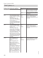
Troubleshooting, Vitotronic 300-K
Fault codes (cont.)
57
58
59
5C
System characteris- Cause
tics
Control mode.
Maintenance or
fault on
Vitotronic 100 of
boiler 7.
Control mode.
Maintenance or
fault on
Vitotronic 100 of
boiler 8.
Cylinder primary
Lead break, cylinpump "ON":
der temperature
Set DHW temperasensor 1
ture = set flow temperature
Priority control is cancelled.
or
With primary store
system:
Cylinder heating is
started and stopped
by cylinder temperature sensor 2.
With primary store
Lead break, cylinsystem:
der temperature
Cylinder heating is
sensor 2
started and stopped
by cylinder temperature sensor 1.
Control mode.
Communication
fault, Vitotronic 100
of boiler 5
5d
Control mode.
5E
Control mode.
54
Measures
Check maintenance display or fault code on the
respective Vitotronic 100.
Check maintenance display or fault code on the
respective Vitotronic 100.
Check cylinder temperature sensor (see
page 129).
Check cylinder temperature sensor (see
page 129).
Check and replace cascade communication
module and connecting
cable if required.
Communication
Check and replace casfault, Vitotronic 100 cade communication
of boiler 6
module and connecting
cable if required.
Communication
Check and replace casfault, Vitotronic 100 cade communication
of boiler 7
module and connecting
cable if required.
5601 090 GB
Displayed
fault code
56
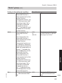
Troubleshooting, Vitotronic 300-K
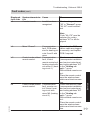
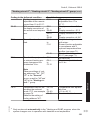
Fault codes (cont.)
System characteris- Cause
tics
Control mode.
Communication
fault, Vitotronic 100
of boiler 8
70
With primary store
system:
3-way mixing valve
"Closed"; no DHW
heating.
With primary store
system:
3-way mixing valve
"Closed"; no DHW
heating.
Short circuit, temperature sensor
aJB
84
Control mode.
85
Control mode.
86
Control mode.
87
Control mode.
8C
Control mode.
Maintenance or
fault on
Vitotronic 100 of
boiler 1
Maintenance or
fault on
Vitotronic 100 of
boiler 2
Maintenance or
fault on
Vitotronic 100 of
boiler 3
Maintenance or
fault on
Vitotronic 100 of
boiler 4
Communication
fault, Vitotronic 100
of boiler 1
8d
Control mode.
5601 090 GB
78
Lead break, temperature sensor
aJB
Measures
Check and replace cascade communication
module and connecting
cable if required.
Check temperature sensor (see page 129).
Check temperature sensor (see page 129).
Without temperature sensor:
Set code "4b:0" in the
"General" group.
Check maintenance display or fault code on the
respective Vitotronic 100.
Check maintenance display or fault code on the
respective Vitotronic 100.
Check maintenance display or fault code on the
respective Vitotronic 100.
Check maintenance display or fault code on the
respective Vitotronic 100.
Check and replace cascade communication
module and connecting
cable if required.
Communication
Check and replace casfault, Vitotronic 100 cade communication
of boiler 2
module and connecting
cable if required.
55
Service
Displayed
fault code
5F
Troubleshooting, Vitotronic 300-K
Fault codes (cont.)
System characteris- Cause
tics
Control mode.
Communication
fault, Vitotronic 100
of boiler 3
8F
Control mode.
90
Control mode.
91
Control mode.
92
No solar DHW heating.
93
Control mode.
94
No solar DHW heating.
56
Measures
Check and replace cascade communication
module and connecting
cable if required.
Communication
Check and replace casfault, Vitotronic 100 cade communication
of boiler 4
module and connecting
cable if required.
Short circuit, tem- Check temperature senperature sensor / (see separate
sor /,
installation and service
connection at solar instructions).
control module.
Short circuit, tem- Check temperature senperature sensor
sor aÖ (see separate
aÖ,
installation and service
connection at solar instructions).
control module.
Short circuit, colCheck sensor at the solar
lector temperature control unit (see separate
sensor,
installation and service
connection of tem- instructions).
perature sensor
& at solar control
module or sensor
at S1 of the
Vitosolic.
Short circuit, tem- Check sensor at the solar
perature sensor,
control unit (see separate
connection to S3 of installation and service
the Vitosolic.
instructions).
Short circuit, cylin- Check sensor at the solar
der temperature
control unit (see separate
sensor,
installation and service
connection of tem- instructions).
perature sensor
% at solar control
module or sensor
at S2 of the
Vitosolic.
5601 090 GB
Displayed
fault code
8E
Troubleshooting, Vitotronic 300-K
Fault codes (cont.)
System characteris- Cause
tics
Control mode.
Lead break, temperature sensor /,
connection at solar
control module.
99
Control mode.
9A
No solar DHW heating.
9b
Control mode.
9C
No solar DHW heating.
Measures
5601 090 GB
Check temperature sensor / (see separate
installation and service
instructions).
Check coding address
"20" in the "Solar"
group.
Lead break, temCheck temperature senperature sensor
sor aÖ (see separate
aÖ,
installation and service
connection at solar instructions).
control module.
Check coding address
"20" in the "Solar"
group.
Lead break, collec- Check sensor at the solar
tor temperature
control unit (see separate
sensor,
installation and service
connection of tem- instructions).
perature sensor
& at solar control
module or sensor
at S1 of the
Vitosolic.
Lead break, temCheck sensor at the solar
perature sensor,
control unit (see separate
connection to S3 of installation and service
the Vitosolic.
instructions).
Lead break, cylin- Check sensor at the solar
der temperature
control unit (see separate
sensor,
installation and service
connection of tem- instructions).
perature sensor
% at solar control
module or sensor
at S2 of the
Vitosolic.
57
Service
Displayed
fault code
98
Troubleshooting, Vitotronic 300-K
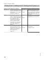
Fault codes (cont.)
Displayed
fault code
9E
9F
Ab
b1
Measures
Check solar circuit.
Acknowledge fault message (see separate installation and service instructions).
Check solar control unit
(see separate installation
and service instructions).
Insert plug aJB and check
codes.
Check connections, and
replace the programming
unit if required.
Check PCB is plugged in
correctly.
5601 090 GB
b5
System characteris- Cause
tics
Control mode.
No flow rate in
solar circuit or flow
rate too low, or
temperature limiter
has responded.
Control mode.
Solar control module or Vitosolic
fault.
Displayed if a fault
occurs at these
devices and has no
fault code in the
Vitotronic.
Control mode, DHW Primary store syscylinder may be cold. tem configuration
fault:
Code "55:3" has
been selected in
the "DHW" group,
but plug aJB is not
plugged in and/or
codes "4C:1" and
"4E:2" in the "General" group have
not been set.
Control mode.
Communication
fault, programming
unit
Control mode.
Internal fault
58
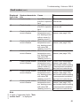
Troubleshooting, Vitotronic 300-K
Fault codes (cont.)
Displayed
fault code
b6
System characteris- Cause
tics
Constant mode.
Invalid hardware
recognised
Measures
Check coding address
"92" in "General" group;
"92:187" must be selected.
Note
Code "8A:176" must be
selected for coding
address "92" to be displayed.
bC
5601 090 GB
bd
Mixer "Closed".
Communication
fault, PCB extension for heating circuits 2 and 3 with
mixer
Control mode without Communication
remote control.
fault, Vitotrol
remote control unit,
heating circuit without mixer A1 (heating circuit 1)
Control mode without Communication
remote control.
fault, remote control Vitotrol, heating circuit with
mixer M2 (heating
circuit 2)
Check that the PCB and
ribbon cable are plugged
in correctly, and replace
PCB if required.
Check connections, lead
(see separate installation
and service instructions)
and coding address "A0"
in the "Heating circuit..." group.
With wireless remote control:
Place the remote control
near the wireless base
station and check connection.
Check connections, lead
(see separate installation
and service instructions)
and coding address "A0"
in the "Heating circuit..." group.
With wireless remote control:
Place the remote control
near the wireless base
station and check connection.
59
Service
bA
Troubleshooting, Vitotronic 300-K
Fault codes (cont.)
System characteris- Cause
tics
Control mode without Communication
remote control.
fault, Vitotrol
remote control with
mixer M3 (heating
circuit 3)
bF
Control mode.
No communication
via LON.
Control mode.
C2
CF
d3
d5
d6
60
Incorrect LON
communication
module
Lead break, KM
BUS to solar control module or
Vitosolic
Measures
Check connections, lead
(see separate installation
and service instructions)
and coding address "A0"
in the "Heating circuit..." group.
With wireless remote control:
Place the remote control
near the wireless base
station and check connection.
Replace LON communication module.
Check KM BUS cable and
device.
Without solar control unit:
Set code "54:0" in the
"General" group.
Control mode.
Communication
Check LON communicaNo communication
fault, control unit
tion module and replace if
via LON.
LON communica- required.
tion module
If no LON communication
module is installed, set
code "76:0" in the "General" group.
Control mode.
Communication
Check connections (see
fault, extenpage 137).
sion EA1
Without extension EA1:
Set code "5b:0" in the
"General" group.
Boiler ramps to the
Boiler does not log Check communication via
electronic maximum in at the cascade
subscriber check, leads/
boiler water tempera- control unit
cables to the
ture limit.
Vitotronic 100 and codes.
Control mode.
Input DE1 at exten- Remove fault at appliance
sion EA1 reports a concerned.
fault
5601 090 GB
Displayed
fault code
bE
Troubleshooting, Vitotronic 300-K
Fault codes (cont.)
d8
dA
db
dC
dd
dE
5601 090 GB
dF
System characteris- Cause
tics
Control mode.
Input DE2 at extension EA1 reports a
fault
Control mode.
Input DE3 at extension EA1 reports a
fault
Control mode without Short circuit, room
room influence.
temperature sensor, heating circuit
without mixer A1
(heating circuit 1)
Control mode without Short circuit, room
room influence.
temperature sensor, heating circuit
with mixer M2
(heating circuit 2)
Control mode without Short circuit, room
room influence.
temperature sensor, heating circuit
with mixer M3
(heating circuit 3)
Control mode without Lead break, room
room influence.
temperature sensor, heating circuit
without mixer A1
(heating circuit 1)
Control mode without Lead break, room
room influence.
temperature sensor, heating circuit
with mixer M2
(heating circuit 2)
Control mode without Lead break, room
room influence.
temperature sensor, heating circuit
with mixer M3
(heating circuit 3)
Measures
Remove fault at appliance
concerned.
Remove fault at appliance
concerned.
Check room temperature
sensor (see page 129).
Check room temperature
sensor (see page 129).
Check room temperature
sensor (see page 129).
Check room temperature
sensor (see page 129)
and remote control setting
(see separate installation
and service instructions).
Check room temperature
sensor (see page 129)
and remote control setting
(see separate installation
and service instructions).
Check room temperature
sensor (see page 129)
and remote control setting
(see separate installation
and service instructions).
Note
In case of subscriber faults, "Subscriber fault" ... is displayed.
61
Service
Displayed
fault code
d7
Function description, Vitotronic 100 and Vitotronic 300-K
Boiler water temperature control of the Vitotronic 100
Brief description
■ The boiler water temperature is regulated by switching the modulating
burner.
■ The set boiler water temperature is
defaulted by the Vitotronic 300-K.
Functions
The boiler water temperature is recorded
separately:
■ Temperature limiter
■ Boiler water temperature sensor
Upper control range limits
Electronic maximum boiler water temperature limit:
■ Setting range: 20 °C to boiler coding
card default
■ Changed via coding address "06" in
group 2
Control sequence
The boiler goes cold:
■ The burner start signal is selected as
the set boiler water temperature –4 K,
and the burner starts its own monitoring program.
■ You can delay the burner start by several minutes.
Boiler heats up:
■ The burner shutdown point is determined by the shutdown differential of
8 K.
Cascade control of the Vitotronic 300-K
Brief description
62
■ Subject to the system design, you may
select between one condensing strategy and two conventional boiler strategies.
5601 090 GB
■ The flow temperature is regulated by
starting or stopping the burner or by
modulating the individual burners.
■ The boilers will be regulated to the set
boiler water temperature defaulted by
the cascade control unit (standalone
control).
Function description, Vitotronic 100 and Vitotronic 300-K
Cascade control of the Vitotronic 300-K (cont.)
■ The boiler sequence (see page 35)
can be determined via code 2 and the
boiler sequence selection control.
■ Coding addresses that influence the
cascade control:
"Cascade" group.
For a description, see codes overview.
Set flow temperature
Upper control range limits
■ Maximum limit of the system flow temperature (coding address "37" in the
"Cascade" group).
Lower control range limits
■ Minimum limit of the system flow temperature (coding address "36" in the
"Cascade" group).
5601 090 GB
Service
The set flow temperature is determined
from the following parameters:
■ Set flow temperature of the heating circuit without mixer A1 and the heating
circuits with mixer M2 and M3 (if installed)
■ Set flow temperature of additional consumers (e.g. specified by
Vitotronic 200-H)
■ Set DHW temperature
■ External demands (e.g. the set flow
temperature specified by coding
address "9b" or via set flow temperature specified by input "0 to 10 V" of
the extension EA1)
63
Function description, Vitotronic 100 and Vitotronic 300-K
Cascade control of the Vitotronic 300-K (cont.)
Standalone control
Boilers connected in parallel
Control strategies
■ Without and with flow temperature
sensor.
– With flow temperature sensor:
Set code "3b:1" in the "Cascade"
group.
The control deviation is calculated
from the set flow temperature and
the actual flow temperature to determine the start and shutdown criteria.
– Without flow temperature sensor:
Set code "3b:0" in the "Cascade"
group.
To determine the start and stop criteria, the control deviation is calculated from the set boiler water temperature and the estimated average
actual boiler water temperature of
the currently active boilers.
■ The cascade control specifies the set
boiler water temperature for all currently active boilers. Every boiler control unit regulates to the specified set
value.
Condensing strategy
Operation with positive pressure flue
gas cascade
Code "7E:1" in the "General" group.
When each additional boiler starts, all
currently active burners are briefly ramped up to over 80 %.
64
Conventional strategy 1
Benefit:
As few boilers as possible are active.
Set code "3C:1" in the "Cascade"
group.
5601 090 GB
The following control strategies are
available:
■ Condensing strategy (see page 64)
■ Conventional boiler strategy 1 (see
page 64)
■ Conventional boiler strategy 2 (see
page 65)
Benefit:
Optimum utilisation of the condensing
effect and long burner runtimes.
Set code "3C:0" in the "Cascade"
group.
It is the aim of the condensing strategy
to operate as many boilers as possible at
the lowest output level.
■ Starting criterion:
Boilers are started via an output statement (code "3d:1" in the "Cascade"
group).
An additional boiler will start if the currently required output can also be achieved by the currently active boilers
plus the next boiler in the boiler
sequence (see page 35).
■ Shutdown criterion:
The boilers are shut down via a shutdown integral. The shutdown criterion
is met when the shutdown integral
exceeds a limit set via coding address
"46" in the "Cascade" group and the
boiler started last will be shut down.
Function description, Vitotronic 100 and Vitotronic 300-K
Cascade control of the Vitotronic 300-K (cont.)
With this strategy, an additional boiler
will only be started if the maximum output of all currently active burners is insufficient to achieve the set flow temperature. A boiler will be shut down when the
remaining boilers can achieve the
required output on their own.
■ Starting criterion:
The boilers are started via a starting
integral. The next boiler in the boiler
sequence will be started if the value
set in coding address "45" in the "Cascade" group is exceeded (see
page 35).
■ Shutdown criterion:
Boilers are shut down via an output
statement (code "3d:1" in the "Cascade" group). A boiler is shut down
when the currently required output can
be achieved without the boiler that was
started last.
Conventional strategy 2
5601 090 GB
Service
Benefit:
Long burner runtimes.
Code "3C:2" in the "Cascade" group
(delivered condition).
An additional boiler will only be started if
the maximum output of all currently
active burners is insufficient to achieve
the set flow temperature.
A boiler will be shut down if the burners
were returned to their minimum output
because of a large negative control deviation and the output is still too high.
■ Starting criterion:
The boilers are started via a starting
integral. The next boiler in the boiler
sequence will be started if the value
set in coding address "45" in the "Cascade" group is exceeded (see
page 35).
■ Shutdown criterion:
The boilers are shut down via a shutdown integral. The shutdown criterion
is met when the shutdown integral
exceeds a limit set via coding address
"46" in the "Cascade" group and the
boiler started last will be shut down.
65
Function description, Vitotronic 100 and Vitotronic 300-K
Cascade control of the Vitotronic 300-K (cont.)
Examples of the various control strategies
System with 2 Vitodens 200-W.
Condensing strategy (code "3C:0" in the "Cascade" group)
Boiler 1
100
Rated output in %
Total
Boiler 2
Shutdown
100
60
25
0
Rated output in %
Total
Boiler 2
Boiler 1
Starting
100
60
25
0
100
25
0
200
150
100
t
25
0
t
5601 090 GB
25
0
25
0
200
150
100
66
Function description, Vitotronic 100 and Vitotronic 300-K
Cascade control of the Vitotronic 300-K (cont.)
Conventional boiler strategy 1 (code "3C:1" in the "Cascade" group)
Boiler 1
100
50
0
200
150
100
Rated output in %
Total
Boiler 2
Shutdown
100
50
25
0
25
0
100
50
25
0
100
50
0
200
150
100
t
25
0
t
5601 090 GB
Service
Rated output in %
Total
Boiler 2
Boiler 1
Starting
67
Function description, Vitotronic 100 and Vitotronic 300-K
Cascade control of the Vitotronic 300-K (cont.)
Conventional boiler strategy 2 (code "3C:2" in the "Cascade" group)
Boiler 1
100
50
0
200
150
100
Rated output in %
Total
Boiler 2
Shutdown
100
50
25
0
Rated output in %
Total
Boiler 2
Boiler 1
Starting
25
0
100
60
25
0
100
25
0
200
150
100
t
25
0
t
Heating circuit control unit of the Vitotronic 300-K
Brief description
68
■ The flow temperature of the heating
circuit without mixer corresponds to
the common system flow temperature.
■ The flow temperature of the heating
circuits with mixer is regulated by the
stepped opening or closing of the mixers.
The mixer motor control changes the
actuating and pause times subject to
the control differential (control deviation).
5601 090 GB
■ The control unit has control circuits for
one heating circuit without mixer A1
(heating circuit 1) and two heating circuits with mixer M2 (heating circuit 2)
and M3 (heating circuit 3).
■ The set flow temperature of every
heating circuit is determined from the
following parameters:
– Outside temperature
– Set room temperature
– Operating mode
– Heating curve slope and level
Function description, Vitotronic 100 and Vitotronic 300-K
Heating circuit control unit of the Vitotronic… (cont.)
Functions
Time program
In accordance with the time program in
the "Heating and DHW" heating program, the control unit switches between
"Central heating with standard room
temperature" and "Central heating with
reduced room temperature".
Every operating mode has its own set
level.
4 time phases per day can be selected.
Outside temperature
Room temperature
In conjunction with the remote control
and room temperature hook-up (coding
address "b0" in the "Heating circuit..."
group):
Compared with the outside temperature,
the room temperature has a greater influence on the set flow temperature
(changed via coding address "b2" in the
"Heating circuit..." group).
In conjunction with heating circuits with
mixer:
For control differentials (actual value
deviation) above 2 K room temperature,
the influence can be increased again
(coding address "b6" in the "Heating circuit..." group):
■ Quick heat-up
The set room temperature must be
raised by at least 2 K by the following
measures:
– Activating party mode
– Changeover from central heating
with reduced temperature to central
heating with standard temperature
– Start optimisation (coding address
"b7" in the "Heating circuit..."
group)
Quick heat-up will stop when the set
room temperature has been reached.
5601 090 GB
A heating curve must be set up for
matching the control unit to the building
and the heating system.
The heating curve characteristics determine the set boiler water temperature
subject to outside temperature. The control unit uses an average outside temperature. This comprises the actual and
the adjusted outside temperature.
69
Service
The heating circuit without mixer is subject to the common flow temperature and
its control range limits.
The heating circuit pump is the only
actuator.
The flow temperature of the heating circuits with mixer is captured by the flow
temperature sensor of the relevant heating circuit.
■ Upper control limit:
Electronic maximum flow temperature
limit
Coding address "C6" in the "Heating
circuit..." group.
■ Lower control range limit:
Electronic minimum flow temperature
limit
Coding address "C5" in the "Heating
circuit..." group.
Function description, Vitotronic 100 and Vitotronic 300-K
Heating circuit control unit of the Vitotronic… (cont.)
■ Quick setback
The set room temperature must be
reduced by at least 2 K by the following
measures:
– Activating economy mode
– Changeover from central heating
with standard temperature to central
heating with reduced temperature
– Stop optimisation (coding address
"C1" in the "Heating circuit..."
group)
Quick setback ends when the set room
temperature has been reached.
DHW temperature
Priority control
■ With priority control: (code "A2:2" in
the "Heating circuit..." group):
During cylinder heating, the set flow
temperature is set to 0 °C.
The mixer closes and the heating circuit pump is switched off.
■ Without priority control:
The heating circuit control unit continues to operate with the same set
value.
Heating circuit pump logic (economy
mode)
The heating circuit pump is switched off
(set flow temperature set to 0 °C) if one
of the following criteria is met:
■ The adjusted outside temperature
exceeds the value selected via coding
address "A6" in the "Heating circuit..." group.
■ The heating circuit pump can be
switched off for a time calculated by
the control unit when changing over
from heating mode to reduced mode.
Requirement:
– There is no risk of frost.
– Coding address "b0" in the "Heating
circuit..." group must be set to 0.
The idle period can be individually
adjusted via coding address "A9" in
the "Heating circuit..." group.
Note
If, during the pump idle period, the system is switched over to heating mode
or the set room temperature is
increased, the heating circuit pump is
switched on, even if the period has not
yet expired.
■ The actual room temperature exceeds
the value selected via coding address
"b5" in the "Heating circuit..." group.
■ The mixer has been closed for 12 min.
(mixer economy function, coding
address "A7" in the "Heating circuit..." group).
5601 090 GB
The heating circuit pump is switched off
(set flow temperature set to 0 °C) if the
outside temperature exceeds the value
selected via coding address "A5" in the
"Heating circuit..." group.
Extended economy mode
70
Function description, Vitotronic 100 and Vitotronic 300-K
Heating circuit control unit of the Vitotronic… (cont.)
Screed drying function
■ In conjunction with a heating circuit
with mixer.
■ For drying screeds (observe the information provided by the screed manufacturer).
■ The heating circuit pump of the heating
circuit with mixer is switched on and
the flow temperature is maintained in
accordance with the selected profile.
■ After completion (30 days), the mixer
circuit will again be regulated automatically via the set parameters.
■ Observe EN 1264.
■ The report to be provided by the heating contractor must contain the following heat-up details:
– Heat-up data with respective flow
temperatures
– Max. flow temperature achieved
– Operating conditions and outside
temperature during handover of the
heating system
■ The various temperature profiles are
adjustable via coding address "F1" in
the "Heating circuit..." group.
■ The function continues after power
failure or after the control unit has
been switched off. The "Heating and
DHW" heating program will be enabled if the screed drying function is terminated or if code "F1:0" is manually
adjusted.
1
5
10
15
20
25
Service
50
40
30
20
10
30
Days
5601 090 GB
Flow
temperature °C
Temperature profile 1: (EN 1264-4) code "F1:1"
71
Function description, Vitotronic 100 and Vitotronic 300-K
Heating circuit control unit of the Vitotronic… (cont.)
Flow
temperature °C
Temperature profile 2: (ZV parquet and flooring technology) code "F1:2"
50
40
30
20
10
1
5
10
15
20
25
30
Days
25
30
Days
25
30
Days
Flow
temperature °C
Temperature profile 3: Code "F1:3"
50
40
30
20
10
1
5
10
15
20
Flow
temperature °C
Temperature profile 4: Code "F1:4"
50
40
30
20
10
1
5
10
15
20
72
50
40
30
20
10
1
5
10
15
20
25
30
Days
5601 090 GB
Flow
temperature °C
Temperature profile 5: Code "F1:5"
Function description, Vitotronic 100 and Vitotronic 300-K
Heating circuit control unit of the Vitotronic… (cont.)
Flow
temperature °C
Temperature profile 6: Code "F1:6"
60
50
40
30
20
10
1
5
10
15
20
25
30
Days
25
30
Days
50
40
30
20
10
1
5
10
15
20
System dynamics
You can influence the control characteristics of the mixers via coding address
"C4" in the "Heating circuit..." group.
5601 090 GB
Central control
Central control for a heating circuit can
be programmed via coding address
"7A" in the "General" group.
The heating and holiday program then
applies to all additional heating circuits
of the system.
For these heating circuits, when the
heating and holiday program is enabled,
"Central control" is displayed. Any holiday programs that may have been set
will be deleted.
Party and economy modes cannot be
enabled on all control units.
Frost protection
The flow temperature is maintained in
accordance with the heating curve for
the reduced set room temperature, but at
min. 10 °C.
A variable frost limit can be set in accordance with coding address "A3" in the
"Heating circuit..." group.
73
Service
Flow
temperature °C
Temperature profile 7: Code "F1:15"
Function description, Vitotronic 100 and Vitotronic 300-K
Heating circuit control unit of the Vitotronic… (cont.)
Flow temperature control
110
Flow temperature in °C
+8 K
B
80
A
D
C
8K
E
+20
-20
Outside temperature in °C
A Maximum flow temperature limit
(coding address "37" in the "Cascade" group)
B Slope = 1.8 for heating circuit without mixer
C Slope = 1.2 for heating circuit with
mixer
D Common flow temperature (at a differential temperature = 8 K)
E Lower common flow temperature
Raising the reduced room temperature
During operation with reduced room
temperature, the reduced set room temperature can be automatically raised
subject to the outside temperature. The
temperature is raised in accordance with
the selected heating curve, but no higher
than the set standard room temperature.
The outside temperature limits for the
start and end of the temperature raising
can be adjusted via coding addresses
"F8" and "F9".
5601 090 GB
Differential temperature:
The differential temperature is adjustable via coding address "9F" in the "General" group,
delivered condition 8 K.
The differential temperature is the value
by which the common flow temperature
should be higher than the highest currently required flow temperature of the
heating circuit with mixer.
■ System with only one heating circuit
with mixer:
The common set flow temperature is
regulated automatically to 8 K above
the set flow temperature of the heating
circuit with mixer.
■ System with heating circuit without
mixer and heating circuits with mixer:
The common set flow temperature
operates in accordance with its own
heating curve. The differential temperature of 8 K towards the set flow temperature of the heating circuits with
mixer is set at the factory.
74
Function description, Vitotronic 100 and Vitotronic 300-K
Heating circuit control unit of the Vitotronic… (cont.)
Example using the settings in the delivered condition
Boiler water or
Flow temperature in °C
90
80
A
70
60
50
B
40
35
30
3
Se 0 2
t ro
5
om
tem 20
10 5
per 15
atu
1
re
in ° 0 5
C
0
-5 -10 -15 -20
Outside temp. in °C
0
B Heating curve for operation with
reduced room temperature
Reducing the heat-up time
The value and duration of the additional
increase of the set boiler water temperature or flow temperature is adjusted in
coding addresses "FA" and "Fb".
5601 090 GB
During the transition from operation with
reduced room temperature to operation
with standard room temperature, the
boiler water or flow temperature will be
raised in accordance with the selected
heating curve. The boiler water or flow
temperature increase can be automatically raised.
Service
A Heating curve for operation with
standard room temperature
75
Function description, Vitotronic 100 and Vitotronic 300-K
Heating circuit control unit of the Vitotronic… (cont.)
Example using the settings in the delivered condition
60
Set boiler water or flow
temperature in °C
50
C
D
B
40
30
20
10
0
A
600
Time in h
700
800
A Start of operation with standard
room temperature
B Set boiler water or flow temperature
in accordance with the selected
heating curve
C Set boiler water or flow temperature
in accordance with the selected coding address "FA":
50 °C + 20 % = 60 °C
900
D Duration of operation with raised set
boiler water or flow temperature in
accordance with coding address
"Fb":
60 min
Control sequence
Mixer circuit
5601 090 GB
The mixer motor will not be controlled
within the "neutral zone" (±1 K).
Flow temperature drops
(Set value −1 K)
The mixer motor receives the signal
"Mixer open". The signal duration lengthens with an increasing control differential. The duration of pauses reduces with
an increasing control differential.
76
Function description, Vitotronic 100 and Vitotronic 300-K
Heating circuit control unit of the Vitotronic… (cont.)
Flow temperature rises
(Set value +1 K)
The mixer motor receives the signal
"Mixer closed". The signal duration
lengthens with an increasing control differential. The duration of pauses
reduces with an increasing control differential.
Cylinder temperature control
Brief description
■ The cylinder temperature control is a
constant temperature control function.
It works by starting and stopping the
circulation pump for cylinder heating.
The switching differential is ±2.5 K.
■ When the DHW cylinder is heated, a
set flow temperature is specified that
is 20 K higher than the set DHW temperature (adjustable via coding
address "60" in the "DHW" group).
Functions
5601 090 GB
An automatic or an individual time program may be selected for DHW heating
and the DHW circulation pump.
Compared with the heating circuit heatup phase, DHW heating starts 30 min
earlier in automatic mode.
The individual time program enables up
to 4 time phases per day to be set for
DHW heating and the DHW circulation
pump for every day of the week.
All cylinder heating sequences will be
completed independently of the time program.
In conjunction with coding address
"7F" in the "General" group
■ Detached house
Code "7F:1":
– Automatic mode
The heating times for heating circuit 1 are applied to systems with
two or three heating circuits.
– Individual time program
The time phases for DHW heating
and the DHW circulation pump have
the same effect on all heating circuits.
77
Service
Time program
Function description, Vitotronic 100 and Vitotronic 300-K
Cylinder temperature control (cont.)
■ Apartment building
Code "7F:0":
– Automatic mode
For systems with two or three heating circuits, the heating times for the
relevant heating circuit will be
applied.
– Individual time program
The time phases for DHW heating
and the DHW circulation pump can
be adjusted individually for each
heating circuit.
Set DHW temperature
The set DHW temperature is adjustable
between 10 and 60 ºC.
The set range can be extended up to
95 °C via coding address "56" in the
"DHW" group.
The set default value of the programming
unit and/or the Vitotrol 300A remote control units can be allocated via coding
address "66" in the "DHW" group.
DHW circulation pump
Priority control
■ With priority control: (code "A2:2" in
the "Heating circuit..." group):
During cylinder heating, the set flow
temperature is set to 0 °C.
The mixer closes and the heating circuit pump is switched off.
■ Without priority control:
The heating circuit control unit continues to operate with the same set
value.
This delivers hot water to the draw-off
points at adjustable times.
Four time phases can be selected at the
control unit for every day.
Auxiliary circuits
DHW heating in conjunction with the
heating circuits can be blocked or enabled by changing over the heating program (see code "d5" in the "Heating circuit..." group).
Frost protection
System with primary store system
Auxiliary function for DHW heating
This function is activated by providing a
second set DHW temperature via coding
address "58" in group "DHW" and activating the fourth DHW phase for DHW
heating.
78
The above functions also apply in conjunction with primary store systems.
Set the following codes:
"55:3" in the "DHW" group, "4C:1", "4E:
2" in the "General" group.
System with solar control unit
A third set DHW temperature can be
specified via coding address "67" in the
"DHW" group.
The DHW cylinder is only reheated by
the boiler if the temperature falls below
this value.
5601 090 GB
The DHW cylinder will be heated to
20 °C if the DHW temperature sinks
below 5 ºC.
Function description, Vitotronic 100 and Vitotronic 300-K
Cylinder temperature control (cont.)
Control sequence
The DHW cylinder goes cold (set value
–2.5 K; adjustable via coding address
"59"):
■ The common set flow temperature is
set 20 K higher than the set DHW temperature (change via coding address
"60").
The DHW cylinder is hot (set value
+2.5 K):
■ The common set flow temperature is
returned to the set weather-compensated value.
■ Pump run-on:
The circulation pump runs on after cylinder heating until one of the following
criteria is met:
– The weather-compensated set flow
temperature has been reached.
– The set DHW temperature is exceeded by 5 K.
– The set max. run-on time is reached
(coding address "62").
■ Without pump run-on (code "62:0")
Code "55:1" in the "DHW" group,
adaptive cylinder heating
The DHW cylinder is hot:
■ The control unit checks whether the
boiler will be required to supply heating
energy after the cylinder has been
heated up or whether residual boiler
heat should be transferred to the DHW
cylinder.
Accordingly, the control unit determines the burner and circulation pump
stop times to prevent the set DHW
temperature being substantially
exceeded after the cylinder has been
heated up.
Code "55:2" in the "DHW" group, cylinder temperature control with 2 cylinder temperature sensors
Cylinder temperature sensor 1 enables
the circulation pump for cylinder heating
and is evaluated for stop conditions during the pump run-on time.
Cylinder temperature sensor 2:
Cylinder heating will start early if a lot of
hot water is drawn off. Cylinder heating
will terminate early if no hot water is
drawn off.
5601 090 GB
With adaptive cylinder heating, the
speed of the temperature rise during
DHW heating is taken into account.
The DHW cylinder goes cold (set value
–2.5 K; adjustable via coding address
"59"):
■ The common set flow temperature is
set 20 K higher than the set DHW temperature (change via coding address
"60").
79
Service
Code "55:0" in the "DHW" group, cylinder heating
Function description, Vitotronic 100 and Vitotronic 300-K
Cylinder temperature control (cont.)
DHW cylinder goes cold:
■ Set value –2.5 K, adjustable via coding
address "59"
or
■ Actual DHW temperature at sensor 2
< set DHW temperature x factor for
start time (adjustment via coding
address "69")
The DHW cylinder is hot:
■ Set value +2.5 K
and
■ Actual DHW temperature at sensor 2
> set DHW temperature x factor for
stop time (adjustment via coding
address "68")
The DHW cylinder is hot:
■ (Cylinder temperature sensor 1:
Actual value ≥ set value
and
cylinder temperature sensor 2:
Actual value > set value –1.5 K):
■ The common set flow temperature is
returned to the set weather-compensated value.
■ The circulation pump for cylinder heating stops immediately when the
3-way mixing valve is fully opened.
or
■ The circulation pump for cylinder heating stops after expiry of the run-on time
that is selected via code "62".
The DHW cylinder goes cold (set value
–2.5 K; adjustable via coding address
"59"):
■ The common set flow temperature is
set 20 K higher than the set DHW temperature (change via coding address
"60").
■ The primary pump in the primary store
system starts.
■ The 3-way mixing valve opens and
then regulates to the specified set
value.
■ The circulation pump for cylinder heating cycles (briefly switches on and off)
until the set flow temperature has been
reached (set DHW temperature + 5 K).
Then it runs constantly.
If, during heating, the actual value falls
below the required set temperature,
the circulation pump for cylinder heating will temporarily cycle again.
80
5601 090 GB
Code "55:3" in the "DHW" group, cylinder temperature control, primary
store system
Code 1, Vitotronic 300-K
Calling up coding level 1
Codes for Vitotronic 100:
Boiler service instructions
Note
■ On Vitotronic 300 -K units, codes are
displayed as plain text.
■ Codes that have not been assigned
due to the heating system equipment
level or the setting of other codes are
not displayed.
■ Heating systems with one heating circuit without mixer and one or two heating circuits with mixer:
The heating circuit without mixer is
designated "Heating circuit 1" and
the heating circuits with mixer as
"Heating circuit 2" or "Heating circuit 3".
If the heating circuits were given individual designations, the selected designation and "HC1", "HC2" or "HC3"
appear instead.
1. Press OK and
approx. 4 s.
simultaneously for
3. Select group of required coding
address:
■ "General"
■ "Cascade"
■ "DHW"
■ "Solar"
■ "Heating circuit 1/2/3"
■ "All codes std device"
In this group, all coding addresses
from coding level 1 (except the coding addresses from the "Solar"
group) are displayed in ascending
order.
4. Select coding address.
5. Select value according to the following tables and confirm with OK.
6. If you want to reset all codes to
their delivered condition:
Select "Standard setting" in "Coding level 1".
Note
This also resets codes at coding level
2.
Service
2. "Coding level 1"
"General" group
5601 090 GB
Coding
Coding in the delivered condition
System design
00:1
System version 1:
One heating circuit without mixer A1 (heating circuit 1), without DHW
heating
Possible change
00:2
to
00:10
For system schemes, see
the following table:
81
Code 1, Vitotronic 300-K
"General" group (cont.)
3
4
5
6
7
8
9
10
Description
One heating circuit without mixer A1 (heating circuit 1), with DHW
heating; automatic recognition.
One heating circuit with mixer M2 (heating circuit 2), without DHW
heating.
One heating circuit with mixer (heating circuit 2), with DHW heating.
One heating circuit without mixer A1 (heating circuit 1), one heating circuit with mixer M2 (heating circuit 2), without DHW heating;
automatic recognition.
One heating circuit without mixer A1 (heating circuit 1), one heating circuit with mixer M2 (heating circuit 2), with DHW heating;
automatic recognition.
Two heating circuits with mixer M2 (heating circuit 2) and M3
(heating circuit 3), without DHW heating.
Two heating circuits with mixer M2 (heating circuit 2) and M3
(heating circuit 3), with DHW heating.
One heating circuit without mixer A1 (heating circuit 1), two heating
circuits with mixer M2 (heating circuit 2) and M3 (heating circuit 3),
without DHW heating; automatic recognition.
One heating circuit without mixer A1 (heating circuit 1), two heating
circuits with mixer M2 (heating circuit 2) and M3 (heating circuit 3),
with DHW heating; automatic recognition.
Coding in the delivered condition
Subscriber no.
77:5
LON subscriber number.
Detached house/apartment building
7F:1
Detached house.
82
Possible change
77:2
to
77:99
LON subscriber number,
adjustable from 1 to 99:
1 - 4 = Boiler
5 = Cascade
10 - 97 = Vitotronic 200-H
98 = Vitogate
99 = Vitocom
7F:0
Apartment building
Separate adjustment of
holiday program and time
program for DHW heating
possible.
5601 090 GB
Value address
00: ...
2
Code 1, Vitotronic 300-K
"General" group (cont.)
Coding in the delivered condition
Possible change
Lock out controls
Operation in the standard
8F:0
Operation in the standard 8F:1
menu and extended menu
menu and extended
blocked.
menu enabled.
8F:2
Operation enabled in the
Note
standard menu and
The respective code is
blocked in the extended
only activated when you
menu.
exit the service menu
(see page 47).
Set flow temperature for external demand
9b:70
Set flow temperature for 9b:0
external demand 70 °C. to
9b:127
Set flow temperature for
external demand adjustable from 0 to 127 °C (limited
by boiler-specific parameters).
"Cascade" group
5601 090 GB
Coding in the delivered condition
Possible change
Number of boilers in cascade
35:4
4 boilers connected to the 35:1
1 to 8 boilers connected to
Vitotronic 300-K.
to
the Vitotronic 300-K.
35:8
Min. system flow temperature
36:0
Electronic minimum sys- 36:1
Minimum limit adjustable
tem flow temperature limit to
from 0 to 127 °C.
set to 0 °C.
36:127
83
Service
Coding
Code 1, Vitotronic 300-K
"Cascade" group (cont.)
Coding in the delivered condition
Max. system flow temperature
37:80
Electronic maximum system flow temperature limit
set to 80 °C.
Possible change
37:20
to
37:127
Maximum limit adjustable
from 20 to 127 °C.
Note
Value must not be higher
than the lowest value of
coding address "06" in
group 1 of every
Vitotronic 100.
Control type
3b:1
Standalone parallel boiler 3b:0
connection with flow temperature sensor.
Control strategy
3C:0
Condensing strategy
3C:1
(see page 64).
3C:2
Standalone parallel boiler
connection without flow
temperature sensor.
Conventional boiler strategy 1 (see page 64).
Conventional boiler strategy 2 (see page 65).
"DHW" group
Coding
5601 090 GB
Coding in the delivered condition
Possible change
Set DHW temperature reheating suppression
67:40
For solar DHW heating:
67:0
Set DHW temperature
Set DHW temperature
to
adjustable from 0 to 95 °C
40 °C. Reheating is sup- 67:95
(limited by boiler-specific
pressed above the selecparameters).
ted set temperature
(DHW heating blocked by
the boiler).
84
Code 1, Vitotronic 300-K
"DHW" group (cont.)
Coding in the delivered condition
Enable DHW circulation pump
73:0
DHW circulation pump:
"ON" according to time
program.
Possible change
73:1
to
73:6
73:7
"ON" from once per hour
for 5 min up to 6 times per
hour for 5 min during the
time program.
Constantly "ON".
"Solar" group
Note
The solar group is only displayed if a solar control module, type SM1, is connected.
5601 090 GB
Coding in the delivered condition
Possible change
Speed control solar circuit pump
02:0
Solar circuit pump (multi 02:1
Solar circuit pump (multi
stage) without speed constage) is speed-controlled
trol by solar control modwith wave pack control.
ule SM1.
02:2
Solar circuit pump is
speed-controlled with
PWM control.
Cylinder maximum temperature
08:60
The solar circuit pump
08:10
The maximum cylinder
stops when the actual
to
temperature is adjustable
DHW temperature rea08:90
from 10 to 90 °C.
ches the maximum cylinder temperature (60 °C).
Stagnation time reduction
0A:5
To protect system com0A:0
Stagnation time reduction
ponents and heat transfer
is disabled.
medium:
0A:1
Value for stagnation time
the speed of the solar cir- to
reduction is adjustable
cuit pump is reduced if
0A:40
from 1 to 40 K.
the actual DHW temperature is 5 K below the maximum cylinder temperature.
85
Service
Coding
Code 1, Vitotronic 300-K
"Solar" group (cont.)
Coding in the delivered condition
Flow rate solar circuit
0F:70
The solar circuit flow rate
at maximum pump speed
is 7 l/min.
Extended solar control functions
20:0
No extended control functions enabled.
Possible change
0F:1
to
0F:255
Flow rate adjustable from
0.1 to 25.5 l/min;
1 step ≙ 0.1 l/min.
20:1
Additional function for
DHW heating.
Differential temperature
control 2.
Differential temperature
control 2 and auxiliary function.
Differential temperature
control 2 for central heating
backup.
Thermostat function.
Thermostat function and
auxiliary function.
Solar heating via external
heat exchanger without
additional temperature
sensor.
Solar heating via external
heat exchanger with additional temperature sensor.
Solar heating of two DHW
cylinders.
20:2
20:3
20:4
20:5
20:6
20:7
20:8
5601 090 GB
20:9
86
Code 1, Vitotronic 300-K
"Heating circuit 1", "Heating circuit 2", "Heating circuit 3" group
Coding
Possible change
A2:0
A2:1
A2:3
to
A2:15
Economy function outside temperature
A5:5
With heating circuit pump A5:0
logic function (economy
mode): Heating circuit
A5:1
pump "OFF" when the
to
outside temperature (AT) A5:15
is 1 K higher than the set
room temperature (RTset)
AT > RTset + 1 K
Without heating circuit
pump logic function.
With heating circuit pump
logic function: Heating circuit pump "OFF"; see the
following table.
With heating circuit pump logic function: Heating circuit pump "OFF"
AT > RTset + 5 K
AT > RTset + 4 K
AT > RTset + 3 K
AT > RTset + 2 K
AT > RTset + 1 K
AT > RTset
AT > RTset - 1 K
AT > RTset - 9 K
5601 090 GB
Parameter address
A5:...
1
2
3
4
5
6
7
to
15
Without cylinder priority
applicable to heating circuit
pump and mixer.
Cylinder priority applies
only to mixers.
No function.
87
Service
Coding in the delivered condition
Priority DHW heating
A2:2
Cylinder priority applicable to heating circuit
pump and mixer.
Code 1, Vitotronic 300-K
"Heating circuit 1", "Heating circuit 2", "Heating circuit 3" group (cont.)
Possible change
A7:1
Pump idle time, transition reduced mode
A9:7
With pump idle time:
A9:0
Heating circuit pump
A9:1
"OFF" (see function
to
description on page 70). A9:15
Weather-compensated/room temperature hook-up
b0:0
b0:1
With remote control:*1
Heating mode/reduced
mode: weather-compensated.
b0:2
b0:3
Economy function room temperature
b5:0
b5:1
With remote control:*1
to
No room temperaturedependent heating circuit b5:8
pump logic function.
*1
Change code only for the heating circuits with mixer.
88
With mixer economy function (extended heating circuit pump logic):
Heating circuit pump also
"OFF":
■ If the mixer has been
attempting to close for
longer than 20 min.
Heating circuit pump
"ON":
■ If the mixer changes to
control function.
■ If there is a risk of frost.
Without pump idle time.
With pump idle time;
adjustable from 1 to 15:
1: short idle time
15: long idle time
Max. idle time 10 h.
Heating mode: weathercompensated
Reduced mode: with room
temperature hook-up
Heating mode: with room
temperature hook-up
Reduced mode: weathercompensated
Heating mode/reduced
mode: with room temperature hook-up
Heating circuit pump logic
function, see the following
table.
5601 090 GB
Coding in the delivered condition
Extended economy function mixer
A7:0
Without economy function mixer.
Code 1, Vitotronic 300-K
"Heating circuit 1", "Heating circuit 2", "Heating circuit 3" group (cont.)
With heating circuit pump logic function:
Heating circuit pump "OFF"
Heating circuit pump "ON"
RTactual > RTset + 5 K
RTactual < RTset + 4 K
RTactual > RTset + 4 K
RTactual < RTset + 3 K
RTactual > RTset + 3 K
RTactual < RTset + 2 K
RTactual > RTset + 2 K
RTactual < RTset + 1 K
RTactual > RTset + 1 K
RTactual < RTset
RTactual > RTset
RTactual < RTset - 1 K
RTactual > RTset - 1 K
RTactual < RTset - 2 K
RTactual > RTset - 2 K
RTactual < RTset - 3 K
Coding in the delivered condition
Min. flow temperature heating circuit
C5:20
Electronic minimum flow
temperature limit 20 °C
(only in operation with
standard room temperature).
Max. flow temperature heating circuit
C6:75
Electronic maximum flow
temperature limit set to
75 °C.
Possible change
C5:1
to
C5:127
Minimum limit adjustable
from 1 to 127 °C (limited by
boiler-specific parameters).
C6:10
to
C6:127
Maximum limit adjustable
from 10 to 127 °C (limited
by boiler-specific parameters).
The heating program
changes to "Constant operation with standard room
temperature".
5601 090 GB
Heating program - changeover
d5:0
With external heating pro- d5:1
gram changeover
(observe setting of coding
address "5d", "5E" and
"5F" and "91" in the
"General" group):
The heating program
changes to "Constant
room heating with
reduced room temperature" or "Standby mode"
(subject to the setting of
the set reduced room
temperature).
Service
Parameter
address b5:...
1
2
3
4
5
6
7
8
89
Code 1, Vitotronic 300-K
"Heating circuit 1", "Heating circuit 2", "Heating circuit 3" group (cont.)
*2
Party mode ends automatically in the "Heating and DHW" program, when the
system changes over to operation with standard room temperature.
90
5601 090 GB
Coding in the delivered condition
Possible change
Ext. heating program changeover to heating circuit
d8:0
No heating program
d8:1
Heating program changechangeover via extension
over via input DE1 at extenEA1.
sion EA1.
d8:2
Heating program changeover via input DE2 at extension EA1.
d8:3
Heating program changeover via input DE3 at extension EA1.
Screed function
F1:0
Screed function disaF1:1
Only for heating circuits
bled.
to
with mixer:
F1:6
Screed function adjustable
in accordance with 6
optional temperature/time
profiles (see page 71).
F1:15
Constant flow temperature
20 °C (see page 71).
Party mode time limit
F2:8
Time limit for party mode F2:0
No time limit for party
or external heating promode.*2
gram changeover via
F2:1
Time limit adjustable from 1
pushbutton: 8 h *2
to
to 12 h.*2
F2:12
Note
Observe settings of coding addresses "5d", "5E",
"5F" in the "General"
group, as well as "d5" and
"d8" in the "Heating circuit..." group).
Code 1, Vitotronic 300-K
"Heating circuit 1", "Heating circuit 2", "Heating circuit 3" group (cont.)
Possible change
F8:+10
to
F8:-60
F8:-61
Temperature limit adjustable from +10 to -60 °C.
F9:+10
to
F9:-60
Limit for raising the set
room temperature to the
value selected for standard
mode adjustable from
+10 to -60 °C.
Temperature rise adjustable from 0 to 50 %.
Duration adjustable from 0
to 300 min;
1 step ≙ 2 min.
5601 090 GB
Set flow temperature increase
FA:20
Raising the set boiler
FA:0
water temperature or the to
set flow temperature
FA:50
when changing from
operation with reduced
room temperature to
operation with standard
room temperature, by
20 %. See example on
page 75.
Duration set flow temperature increase
Fb:30
Duration for raising the
Fb:0
set boiler water tempera- to
ture or the set flow tem- Fb:150
perature (see coding
address "FA" in the
"Heating circuit ..."
group) 60 min. See
example on page 75.
Function disabled.
91
Service
Coding in the delivered condition
Start temperature raising
F8:-5
Temperature limit for terminating the reduced
mode -5 ºC, see example
on page 74.
Observe settings of coding address "A3" set in
the "Heating circuit ..."
group.
End temperature raising
F9:-14
Limit for raising the
reduced set room temperature -14 ºC, see
example on page 74.
Code 2, Vitotronic 300-K
Calling up coding level 2
Codes for Vitotronic 100:
Boiler service instructions
Note
■ At coding level 2, all codes are accessible, including the codes at coding
level 1.
■ Codes that have not been assigned
due to the heating system equipment
level or the setting of other codes are
not displayed.
■ Heating systems with one heating circuit without mixer and one or two heating circuits with mixer:
The heating circuit without mixer is
designated "Heating circuit 1" and
the heating circuits with mixer as
"Heating circuit 2" or "Heating circuit 3".
If the heating circuits were given individual designations, the selected designation and "HC1", "HC2" or "HC3"
appear instead.
1. Press OK and
approx. 4 s.
simultaneously for
2. Press OK and
approx. 4 s.
simultaneously for
3. "Coding level 2"
4. Select group of required coding
address:
■ "General"
■ "Cascade"
■ "DHW"
■ "Solar"
■ "Heating circuit 1/2/3"
■ "All codes std device"
In this group, all coding addresses
(except the coding addresses from
the "Solar" group) are displayed in
ascending order.
5. Select coding address.
6. Select value according to the following tables and confirm with "OK".
7. If you want to reset all codes to
their delivered condition:
Select "Standard setting" in "Coding level 2".
Note
This also resets codes at coding level
1.
"General" group
Coding in the delivered condition
00:1
System version 1:
92
Possible change
00:2
For system schemes, see
to
the following table:
00:10
5601 090 GB
Coding
Code 2, Vitotronic 300-K
"General" group (cont.)
Coding in the delivered condition
Possible change
One heating circuit without mixer A1 (heating circuit 1), without DHW
heating
3
4
5
6
7
8
9
5601 090 GB
10
Description
One heating circuit without mixer A1 (heating circuit 1), with DHW
heating (automatic recognition).
One heating circuit with mixer M2 (heating circuit 2), without DHW
heating.
One heating circuit with mixer (heating circuit 2), with DHW heating.
One heating circuit without mixer A1 (heating circuit 1), one heating
circuit with mixer M2 (heating circuit 2), without DHW heating;
automatic recognition.
One heating circuit without mixer A1 (heating circuit 1), one heating
circuit with mixer M2 (heating circuit 2), with DHW heating; automatic recognition.
Two heating circuits with mixer M2 (heating circuit 2) and M3
(heating circuit 3), without DHW heating.
Two heating circuits with mixer M2 (heating circuit 2) and M3
(heating circuit 3), with DHW heating.
One heating circuit without mixer A1 (heating circuit 1), two heating
circuits with mixer M2 (heating circuit 2) and M3 (heating circuit 3),
without DHW heating; automatic recognition.
One heating circuit without mixer A1 (heating circuit 1), two heating
circuits with mixer M2 (heating circuit 2) and M3 (heating circuit 3),
with DHW heating; automatic recognition.
Coding in the delivered condition
12:5
With extension EA1:
DHW circulation pump
runtime for brief operation: 5 min.
1E:0
With extension EA1 (analogue input 0-10 V):
Temperature demand
from 0 to 100 °C:
1 V ≙ 10 °C
10 V ≙ 100 °C
Possible change
12:1
Runtime adjustable from 1
to
to 60 min.
12:60
1E:1
Temperature demand from
30 to 120 °C:
1 V ≙ 30 °C
10 V ≙ 120 °C
93
Service
Value address
00: ...
2
Code 2, Vitotronic 300-K
Coding in the delivered condition
Possible change
2E:0
Without outside tempera- 2E:1
With outside temperature
ture sensor RF.
sensor; automatic recognition.
2E:2
Outside temperature sensor RF is not used.
2F:0
Never adjust.
4A:0
Never adjust.
4b:0
4b:1
Sensor aJB not fitted.
Sensor aJB installed (e.g.
temperature sensor T2);
automatic recognition.
4C:0
Connection on plug
4C:1
Primary pump, primary
store system.
sÖA1:
Heating circuit pump.
4F:5
Distribution pump run-on 4F:0
No pump run-on.
time 5 min.
4F:1
Run-on time adjustable
to
from 1 to 60 min.
4F:60
50:10
Start integral threshold
50:1
Start integral threshold for
for external heat source to
external heat source
set to 10 K x min.
50:255
adjustable from 1 to
255 K x min.
51:255
Shutdown integral
51:1
Shutdown integral threshthreshold for external
to
old for external heat source
heat source set to
51:255
adjustable from 1 to
255 K x min.
255 K x min.
54:0
Without solar thermal
54:1
With Vitosolic 100; autosystem.
matic recognition.
54:2
With Vitosolic 200; automatic recognition.
54:3
With solar control module
SM1 without auxiliary function; automatic recognition.
54:4
With solar control module,
type SM1, with auxiliary
function, e.g. central heating backup; automatic recognition.
5b:0
Without extension EA1.
5b:1
With extension EA1; automatic recognition.
94
5601 090 GB
"General" group (cont.)
Code 2, Vitotronic 300-K
5601 090 GB
Coding in the delivered condition
5C:0
Function, output aBJ at
extension EA1:
Central fault message.
5d:0
Function input DE1 at
extension EA1:
No function.
5E:0
Function input DE2 at
extension EA1:
No function.
Possible change
5C:1
Feed pump.
5C:2
No function.
5C:3
Heating circuit pump A1 is
switched to low speed
(reduced mode).
5C:4
Heating circuit pump M2 is
switched to low speed
(reduced mode).
5C:5
Heating circuit pump M3 is
switched to low speed
(reduced mode).
5d:1
Heating program changeover.
5d:2
External demand with minimum set flow temperature.
Selection of set value in
coding address "9b" in the
"General" group.
5d:3
External blocking.
5d:4
External blocking with fault
message.
5d:5
Fault message input.
5d:6
Brief operation, DHW circulation pump (pushbutton
function).
Setting of runtime for DHW
circulation pump in coding
address "12" in the "General" group.
5E:1
Heating program changeover.
5E:2
External demand with minimum set flow temperature.
Selection of set value in
coding address "9b" in the
"General" group
5E:3
External blocking.
5E:4
External blocking with fault
message.
95
Service
"General" group (cont.)
Code 2, Vitotronic 300-K
Coding in the delivered condition
5F:0
Function input DE3 at
extension EA1:
No function.
6E:50
No display correction of
the outside temperature.
76:0
Without communication
module.
96
Possible change
5E:5
Fault message input.
5E:6
Brief operation, DHW circulation pump (pushbutton
function).
Setting of runtime for DHW
circulation pump in coding
address "12" in the "General" group.
5F:1
Heating program changeover.
5F:2
External demand with minimum set flow temperature.
Selection of set value in
coding address "9b" in the
"General" group.
5F:3
External blocking.
5F:4
External blocking with fault
message.
5F:5
Fault message input.
5F:6
Brief operation, DHW circulation pump (pushbutton
function).
Setting of runtime for DHW
circulation pump in coding
address "12" in the "General" group.
6E:0
Display correction –5 K
to
to
6E:49
Display correction –01 K
6E:51
Display correction +0.1 K
to
to
6E:99
Display correction +4.9 K
76:1
With LON communication
module; automatic recognition.
If no LON communication
module is installed, set
code "76:0" in the "General" group.
5601 090 GB
"General" group (cont.)
Code 2, Vitotronic 300-K
"General" group (cont.)
78:1
79:1
7A:0
7b:1
7F:1
80:6
5601 090 GB
81:1
Possible change
77:2
LON subscriber number,
to
adjustable from 1 to 99:
77:99
1 - 4 = Boiler
5 = Cascade
10 - 97 = Vitotronic 200-H
98: Vitogate
99 = Vitocom
LON communication ena- 78:0
LON communication disabled.
bled.
With LON communication 79:0
Control unit is not fault
module: Control unit is
manager.
fault manager.
Without central control of 7A:1
With central control (see
heating circuits.
page 73)
Heating circuit without
mixer A1 (heating circuit 1).
7A:2
Heating circuit with mixer
M2 (heating circuit M2).
7A:3
Heating circuit with mixer
M3 (heating circuit M3).
With LON communication 7b:0
No time transmission.
module: Control unit
transmits the time.
Detached house.
7F:0
Apartment building.
Separate adjustment of
holiday program and time
program for DHW heating
possible.
A fault message is issued 80:0
Immediate fault message.
if a fault occurs for at least 80:2
The minimum fault duration
30 s.
to
until a fault message is
80:199
issued is adjustable from
10 to 995 s;
1 step ≙ 5 s.
Automatic summer/win81:0
Manual summer/wintertertime changeover.
time changeover.
81:2
The use of the radio clock
receiver will be recognised
automatically.
97
Service
Coding in the delivered condition
77:5
LON subscriber number.
Code 2, Vitotronic 300-K
"General" group (cont.)
82:3
83:5
84:7
85:10
86:5
87:7
88:0
89:...
8A:175
8F:0
90:128
98
Possible change
81:3
With LON communication
module: The control unit
receives the time.
Summer time starts:
82:1
January to December.
March.
to
82:12
Summer time starts:
83:1
Week 1 to week 5 of the
Week 5 of the selected
to
selected month.
month.
83:5
Summer time starts:
84:1
Monday to Sunday.
Last Sunday of the selec- to
ted month.
84:7
Wintertime starts:
85:1
January to December.
October.
to
85:12
Wintertime starts:
86:1
Week 1 to week 5 of the
Week 5 of the selected
to
selected month.
month.
86:5
Wintertime starts:
87:1
Monday to Sunday.
Last Sunday of the selec- to
ted month.
87:7
Temperature unit °C
88:1
Temperature unit
(Celsius).
°F (Fahrenheit).
Never adjust.
Never adjust.
Operation in the standard 8F:1
Operation in standard
menu and extended
menu and extended menu
menu enabled.
blocked.
8F:2
Operation enabled in the
Note
standard menu and
The respective code is
blocked in the extended
only activated when you
menu.
exit the service menu
(see page 47).
Time constant for calculating adjusted outside
temperature 21.3 h.
90:1
to
90:199
Fast (low values) or slow
(high values) matching of
the flow temperature, subject to the set value when
the outside temperature
changes;
5601 090 GB
Coding in the delivered condition
Code 2, Vitotronic 300-K
"General" group (cont.)
91:0
92:186
96:0
5601 090 GB
97:2
Possible change
1 step ≙ 10 min.
Connection at terminals 1 91:1
Contact affects the following heating circuits:
and 2 in plug aVD disaHeating circuit without
bled (external heating
mixer A1 (heating cirprogram changeover)
cuit 1).
(see page 26).
91:2
Heating circuit with mixer
M2 (heating circuit 2).
91:3
Heating circuits without
mixer A1 (heating circuit 1)
and heating circuit with
mixer M2 (heating circuit 2).
91:4
Heating circuit with mixer
M3 (heating circuit 3).
91:5
Heating circuits without
mixer A1 (heating circuit 1)
and heating circuit with
mixer M3 (heating circuit 3).
91:6
Heating circuits with mixer
M2 (heating circuit 2) and
M3 (heating circuit 3).
91:7
Heating circuit without
mixer A1 (heating circuit 1)
and heating circuits with
mixer M2 (heating circuit 2)
and M3 (heating circuit 3).
Never adjust.
Will only be displayed if
"8A:176" is programmed.
Without PCB, extension 96:1
With PCB, extension for
for heating circuits 2 and
heating circuits 2 and 3;
3.
automatic recognition.
With LON communication 97:0
The outside temperature of
module:
the sensor connected to
The control unit sends the
the control unit is only utioutside temperature to
lised internally.
the Vitotronic 200-H.
97:1
The control unit receives
the outside temperature
from the Vitotronic 200-H.
99
Service
Coding in the delivered condition
Code 2, Vitotronic 300-K
"General" group (cont.)
Coding in the delivered condition
98:1
Viessmann system number (in conjunction with
monitoring several systems within one LON system with Vitocom 300).
99:0
Connection at terminals 2
and 3 in plug aVD disabled (external blocking/
External "Mixer close")
(see page 26).
Possible change
98:1
System number adjustable
to
from 1 to 5.
98:5
99:1
99:2
99:3
99:4
99:5
99:6
99:7
99:8
99:9
99:10
99:11
99:12
99:13
99:14
5601 090 GB
99:15
No function.
External "Mixer closed"
Heating circuit with mixer
M2 (heating circuit 2).
No function.
External "Mixer closed"
Heating circuit with mixer
M3 (heating circuit 3).
No function.
External "Mixer closed"
Heating circuits with mixer
M2 (heating circuit 2) and
M3 (heating circuit 3).
No function.
External blocking.
No function.
External blocking/external
"Mixer closed"
Heating circuits with mixer
M2 (heating circuit 2) and
M3 (heating circuit 3).
No function.
External blocking/external
"Mixer closed"
Heating circuit with mixer
M3 (heating circuit 3).
No function.
External blocking/external
"Mixer closed"
Heating circuits with mixer
M2 (heating circuit 2) and
M3 (heating circuit 3).
No function.
100
Code 2, Vitotronic 300-K
5601 090 GB
Coding in the delivered condition
Possible change
9A:0
Connection at terminals 1 9A:1
No function.
and 2 in plug aVD disa9A:2
External "Mixer open"
bled (external "Mixer
Heating circuit with mixer
close") (see page 26).
M2 (heating circuit 2).
9A:3
No function.
9A:4
External "Mixer open"
Heating circuit with mixer
M3 (heating circuit 3).
9A:5
No function.
9A:6
External "Mixer open"
Heating circuits with mixer
M2 (heating circuit 2) and
M3 (heating circuit 3).
9A:7
No function.
9b:70
Set flow temperature for 9b:0
Set value adjustable from 0
external demand 70 °C. to
to 127 °C.
9b:127
9C:20
With LON communication 9C:0
No monitoring.
module:
9C:5
Time adjustable from 5 to
Monitoring LON subscrib- to
60 min.
ers.
9C:60
If there is no response
from a subscriber after
20 min, the values specified inside the control unit
are used. Only then will a
fault message be issued.
9F:8
Differential temperature
9F:0
Differential temperature
8 K; only in conjunction
to
adjustable from 0 to 40 K.
with a heating circuit with 9F:40
mixer M2 (heating circuit 2) and M3 (heating
circuit 3).
101
Service
"General" group (cont.)
Code 2, Vitotronic 300-K
"Cascade" group
Coding
Coding in the delivered condition
Possible change
35:4
4 boilers connected to the 35:1
1 to 8 boilers connected to
Vitotronic 300-K.
to
the Vitotronic 300-K.
35:8
36:0
Electronic minimum sys- 36:1
Minimum limit adjustable
tem flow temperature limit to
from 0 to 127 °C.
set to 0 °C.
36:127
37:80
Electronic maximum sys- 37:20
Maximum limit adjustable
tem flow temperature limit to
from 20 to 127 °C.
set to 80 °C.
37:127
Note
Value must not be higher
than the lowest value of
coding address "06" in the
"Boiler" group of every
Vitotronic 100.
No lead boiler or boiler
38:1
sequence changeover;
see function description
in chapter "Cascade control".
38:2
to
38:200
39:0
No permanent lead
boiler.
3A:0
No permanent last
boiler.
3b:1
Standalone parallel
boiler circuit:
With flow temperature
sensor (see page 64).
39:1
to
39:8
3A:1
to
3A:8
3b:0
3b:2
102
Lead boiler changeover:
Every first day of the
month, the boiler with the
shortest number of hours
run by its burner becomes
the lead boiler.
Lead boiler changeover
after 200 to 20,000 hours
run;
1 step ≙ 100 hours run.
Permanent lead boiler is
boiler ...
Permanent last boiler is
boiler ...
Standalone parallel boiler
circuit:
Without flow temperature
sensor (see page 64).
Standalone serial boiler
circuit:
5601 090 GB
38:0
Code 2, Vitotronic 300-K
"Cascade" group (cont.)
Coding in the delivered condition
3d:1
3E:0
3F:0
5601 090 GB
41:31
Distribution pump will
only run if heat demand
exists.
Without cylinder priority
control for distribution
pump.
No ECO threshold
boiler 1.
42:31
No ECO threshold
boiler 2.
43:31
No ECO threshold
boiler 3.
44:31
No ECO threshold
boiler 4.
45:60
Start integral threshold
set to 60 K x min.
3E:1
3F:1
41:−30
to
41:+30
42:−30
to
42:+30
43:−30
to
43:+30
44:−30
to
44:+30
45:1
to
45:255
Distribution pump always
runs; shutdown through
"External blocking" signal.
With cylinder priority control for distribution pump.
ECO threshold boiler 1
adjustable from −30 to
+30 °C.
ECO threshold boiler 2
adjustable from −30 to
+30 °C.
ECO threshold boiler 3
adjustable from −30 to
+30 °C.
ECO threshold boiler 4
adjustable from −30 to
+30 °C.
Start integral threshold
adjustable from 1 to
255 K x min.
Service
3C:0
Possible change
Without flow temperature
sensor (see page 64).
Condensing strategy
3C:1
Conventional boiler strat(see page 66).
egy 1 (see page 67).
3C:2
Conventional boiler strategy 2 (see page 68).
Output statement for con- 3d:0
No output statement.
densing strategy and
Note
conventional boiler strategy 1.
Vitotronic 300-K regulates
only according to conventional boiler strategy 2.
Note
If the threshold is exceeded, one boiler or one
burner stage is switched
on.
103
Code 2, Vitotronic 300-K
"Cascade" group (cont.)
Coding in the delivered condition
46:10
Shutdown integral
threshold set to
10 K x min.
Possible change
46:1
Shutdown integral threshto
old adjustable from 1 to
46:255
255 K x min.
Note
If the threshold is exceeded, one boiler or one
burner stage is switched
off.
47:15
Stop differential set to
15 K.
47:2
to
47:30
Stop differential adjustable
from 2 to 30 K.
Note
One boiler will be switched
off if the actual flow temperature exceeds the set
flow temperature by this
value.
Never adjust.
Never adjust.
No ECO threshold
boiler 5.
6F:31
No ECO threshold
boiler 6.
74:31
No ECO threshold
boiler 7.
7d:31
No ECO threshold
boiler 8.
65:−30
to
65:+30
6F:−30
to
6F:+30
74:−30
to
74:+30
7d:−30
to
7d:+30
ECO threshold boiler 5
adjustable from −30 to
+30 °C.
ECO threshold boiler 6
adjustable from −30 to
+30 °C.
ECO threshold boiler 7
adjustable from −30 to
+30 °C.
ECO threshold boiler 8
adjustable from −30 to
+30 °C.
5601 090 GB
48:35
49:40
65:31
104
Code 2, Vitotronic 300-K
"DHW" group
Coding
Coding in the delivered condition
55:0
Cylinder heating,
hysteresis ± 2.5 K.
56:0
Set DHW temperature
adjustable from 10 to
60 °C.
Possible change
55:1
Adaptive cylinder heating
enabled (see page 79).
55:2
Cylinder temperature control with 2 cylinder temperature sensors (see
page 79).
55:3
Cylinder temperature control, primary store system
(see page 80).
56:1
Set DHW temperature
adjustable from 10 to
over 60 °C.
Note
Observe the max. permissible DHW temperature.
Without auxiliary function 58:10
for DHW heating.
to
58:60
59:0
Cylinder heating:
Set start point –2.5 K
Set stop point +2.5 K
For DHW heating:
The set flow temperature
is determined by the highest system flow temperature demand.
Scan temperature in the
"Diagnosis" menu,
"General" ("Common
dem. temp"), see
page 47.
During DHW heating, the
common flow temperature is max. 20 K higher
than the set DHW temperature.
5A:0
5601 090 GB
60:20
59:1
to
59:10
5A:1
60:10
to
60:50
Input of a second set DHW
temperature, adjustable
from 10 to 95 °C (observe
coding address "56").
Start point adjustable from
1 to 10 K below set value.
For DHW heating:
The set flow temperature is
determined by the DHW
cylinder flow temperature
demand.
Scan temperature in the
"Diagnosis" menu, "General" ("Common dem.
temp"), see page 47.
The differential between
the common flow temperature and the set DHW temperature is adjustable from
10 to 50 K.
105
Service
58:0
Code 2, Vitotronic 300-K
"DHW" group (cont.)
Coding in the delivered condition
62:10
Circulation pump with a
run-on time of
up to 10 min after cylinder
heating.
64:2
66:4
5601 090 GB
67:40
Possible change
62:0
Circulation pump without
run-on.
62:1
Run-on time adjustable
to
from 1 to 15 min.
62:15
During party mode and
64:0
No DHW heating, DHW cirafter external changeover
culation pump "OFF".
to constant operation with 64:1
DHW heating and DHW cirthe standard room temculation pump "ON"
perature:
according to time proEnable constant DHW
gram.
heating and DHW circulation pump "ON".
Input of the set DHW tem- 66:0
At the control unit programperature:
ming unit.
At the control unit pro66:1
At the control unit programgramming unit and all
ming unit and remote coninstalled Vitotrol 300A
trol heating circuit without
remote controls.
mixer A1 (heating circuit ).
66:2
At the control unit programming unit and remote control heating circuit with
mixer M2 (heating circuit 2).
66:3
At the control unit programming unit and remote control heating circuit with
mixer M3 (heating circuit 3).
66:5
At the remote control heating circuit without mixer A1
(heating circuit 1).
66:6
At the remote control heating circuit with mixer M2
(heating circuit 2).
66:7
At the remote control heating circuit with mixer M3
(heating circuit 3).
For solar DHW heating:
67:0
No set value 3.
106
Code 2, Vitotronic 300-K
"DHW" group (cont.)
72:0
73:0
DHW circulation pump:
"ON" according to time
program.
DHW circulation pump:
Possible change
67:10
Set DHW temperature
to
adjustable from 10 to
67:95
95 °C (limited by boilerspecific parameters).
Observe the setting of coding address "56".
68:2
to
68:10
Factor adjustable from 0.2
to 1;
1 step ≙ 0.1.
69:1
to
69:9
Factor adjustable from 0.1
to 09;
1 step ≙ 0.1.
6A:10
to
6A:255
For heat exchanger set
Vitotrans 222 (240 kW): set
113 s.
Runtime adjustable from
10 to 255 s.
DHW circulation pump
"ON" according to time program.
70:1
71:1
71:2
72:1
72:2
73:1
to
73:6
5601 090 GB
73:7
"OFF" during DHW heating
to set value 1.
"ON" during DHW heating
to set value 1.
"OFF" during DHW heating
to set value 2.
"ON" during DHW heating
to set value 2.
"ON" from once per hour
for 5 min up to 6 times per
hour for 5 min during the
time program.
Constantly "ON".
107
Service
Coding in the delivered condition
Set DHW temperature
40 °C. Reheating is suppressed above the selected set temperature
(DHW heating by the
boiler only if solar energy
is not sufficient).
68:8
With 2 cylinder temperature sensors (code
"55:2"):
Cylinder heating stop
point at set value x 0.8.
69:7
With 2 cylinder temperature sensors (code
"55:2"):
Cylinder heating start
point at set value x 0.7.
6A:75
Runtime, servomotor,
mixing valve, heat
exchanger set, Vitotrans
222, (80 and 120 kW):
75 s.
70:0
DHW circulation pump
"ON" according to time
program when DHW
heating is enabled.
71:0
DHW circulation pump:
"ON" according to time
program.
Code 2, Vitotronic 300-K
"DHW" group (cont.)
Coding in the delivered condition
"ON" according to time
program.
75:0
DHW circulation pump
"ON" during economy
mode according to time
program.
Possible change
75:1
DHW circulation pump
"OFF" during economy
mode.
"Solar" group
Only in conjunction with solar control
module, type SM1.
Coding
Coding in the delivered condition
00:8
The solar circuit pump
starts when the collector
temperature exceeds the
actual DHW temperature
by 8 K.
01:4
The solar circuit pump
stops when the differential between the collector
temperature and the
actual DHW temperature
is less than 4 K.
02:0
Solar circuit pump (multi
stage) without speed control by solar control module SM1.
02:1
02:2
The temperature differen- 03:5
tial between the collector to
temperature and actual
03:20
DHW temperature is
regulated to 10 K.
Solar circuit pump (multi
stage) is speed-controlled
with wave packet control.
Solar circuit pump is
speed-controlled with
PWM control.
The differential temperature control between the
collector temperature and
actual DHW temperature is
adjustable from 5 to 20 K.
5601 090 GB
03:10
Possible change
00:2
The differential between
to
the actual DHW tempera00:30
ture and the start point for
the solar circuit pump is
adjustable from 2 to 30 K.
01:1
The differential between
to
the actual DHW tempera01:29
ture and the stop point for
the solar circuit pump is
adjustable from 1 to 29 K.
108
Code 2, Vitotronic 300-K
5601 090 GB
Coding in the delivered condition
Possible change
04:4
Controller amplification of 04:1
Controller amplification
the speed control 4 %/K. to
adjustable from 1 to
04:10
10 %/K.
05:10
Minimum speed of the
05:2
Minimum speed of the
solar circuit pump 10 % of to
solar circuit pump is adjustthe maximum speed.
05:100
able from 2 to 100 %.
06:75
Maximum speed of the
06:1
Maximum speed of the
solar circuit pump 75 % of to
solar circuit pump is adjustthe maximum possible
06:100
able from 1 to 100 %.
speed.
07:0
Interval function of the
07:1
Interval function of the
solar circuit pump
solar circuit pump switched
switched off.
on.
To capture the collector
temperature more accurately, the solar circuit
pump starts for short
cycles.
08:60
The solar circuit pump
08:10
The maximum cylinder
stops when the actual
to
temperature can be adjusDHW temperature rea08:90
ted from 10 to 90 °C.
ches the maximum cylinder temperature (60 °C).
09:130
The solar circuit pump
09:20
The temperature can be
stops if the collector tem- to
adjusted from 20 to
perature reaches 130 °C 09:200
200 °C.
(maximum collector temperature to protect the
system components).
0A:5
To protect system com0A:0
Stagnation time reduction
ponents and heat transfer
is disabled.
medium:
0A:1
Value for stagnation time
The speed of the solar cir- to
reduction is adjustable
cuit pump is reduced if
0A:40
from 1 to 40 K.
the actual cylinder temperature is 5 K below the
maximum cylinder temperature.
109
Service
"Solar" group (cont.)
Code 2, Vitotronic 300-K
"Solar" group (cont.)
Coding in the delivered condition
0b:0
Frost protection function
for solar circuit switched
off.
0C:1
0d:1
0E:1
Possible change
0b:1
Frost protection function
for solar circuit switched on
(not required with
Viessmann heat transfer
medium).
0C:0
Delta T monitoring
switched off.
Delta T monitoring
switched on.
No flow rate captured in
the solar circuit, or flow
rate too low.
Night circulation monitor- 0d:0
ing switched on.
Unintentional flow rate is
captured in the solar circuit (e.g. at night).
Calculation of solar yield 0E:2
with Viessmann heat
transfer medium.
0E:0
0F:70
10:0
0F:1
to
0F:255
10:1
11:10
to
11:90
Calculation of solar yield
with water as heat transfer
medium (never select, as
operation is only possible
with Viessmann heat transfer medium).
Calculation of solar yield
switched off.
Flow rate adjustable from
0.1 to 25.5 l/min.
1 step ≙ 0.1 l/min
Target temperature control
switched on.
Set solar DHW temperature adjustable from 10 to
90 °C.
5601 090 GB
11:50
The solar circuit flow rate
at maximum pump speed
is 7 l/min.
Target temperature control switched off (see coding address "11").
Set solar DHW temperature 50 °C.
Night circulation monitoring switched off.
110
Code 2, Vitotronic 300-K
"Solar" group (cont.)
Possible change
12:0
12:1
to
12:90
20:1
20:2
20:3
20:4
20:5
20:6
5601 090 GB
20:7
Minimum collector temperature function switched
off.
The minimum collector
temperature can be adjusted from 1 to 90 °C.
Additional function for
DHW heating.
Differential temperature
control 2.
Differential temperature
control 2 and auxiliary function.
Differential temperature
control 2 for central heating
backup.
Thermostat function.
Thermostat function and
auxiliary function.
Solar heating via external
heat exchanger without
additional temperature
sensor.
111
Service
Coding in the delivered condition
■ Target temperature
control switched on
(code "10:1"):
Temperature at which
the solar heated water
in the DHW cylinder is
to be stratified.
■ Extended control functions set to heat two
DHW cylinders (code
"20:8"):
When one DHW cylinder reaches its set
DHW temperature, the
second DHW cylinder
is heated.
12:10
Minimum collector temperature 10 °C.
The solar circuit pump will
only start when the set
minimum collector temperature is exceeded.
20:0
No extended control functions enabled.
Code 2, Vitotronic 300-K
"Solar" group (cont.)
22:8
23:4
24:40
112
Start temperature differential for central heating
backup: 8 K.
Switching output sS
starts when the temperature at sensor /
exceeds the temperature
at sensor aÖ by the selected value.
Stop temperature differential for central heating
backup: 4 K.
Switching output sS
stops when the temperature at sensor / undershoots the stop point. The
stop point is the sum of
the temperature at sensor
aÖ and the value selected
as stop temperature differential.
Start temperature for
thermostat function
40 °C.
Start temperature for
thermostat function ≤
stop temperature for thermostat function:
Thermostat function, e.g.
for reheating. Switching
output sS is switched on
when the temperature at
sensor / undershoots
the start temperature for
the thermostat function.
Possible change
20:8
Solar heating via external
heat exchanger with additional temperature sensor.
20:9
Solar heating of two DHW
cylinders.
22:2
Start temperature differento
tial for central heating
22:30
backup is adjustable from 2
to 30 K.
23:2
to
23:30
Stop temperature differential for central heating
backup is adjustable from 1
to 29 K.
24:0
to
24:100
Start temperature for thermostat function is adjustable from 0 to 100 K.
5601 090 GB
Coding in the delivered condition
Code 2, Vitotronic 300-K
5601 090 GB
"Solar" group (cont.)
Possible change
25:0
to
25:100
Stop temperature for thermostat function is adjustable from 0 to 100 K.
26:0
Priority for DHW cylinder 1
– without alternate heating.
Service
Coding in the delivered condition
Start temperature for
thermostat function >
stop temperature for thermostat function:
Thermostat function, e.g.
for utilising excess heat.
Switching output sS is
switched on when the
temperature at sensor / exceeds the start
temperature for the thermostat function.
25:50
Stop temperature for
thermostat function
50 °C.
Start temperature for
thermostat function ≤
stop temperature for thermostat function:
Thermostat function e.g.
for reheating. Switching
output sS is switched off
when the temperature at
sensor / exceeds the
start temperature for the
thermostat function.
Start temperature for
thermostat function >
stop temperature for thermostat function:
Thermostat function e.g.
for utilising excess heat.
Switching output sS is
switched off when the
temperature at sensor / undershoots the
start temperature for the
thermostat function.
26:1
Priority for DHW cylinder
1 – with alternate heating.
113
Code 2, Vitotronic 300-K
"Solar" group (cont.)
Coding in the delivered condition
Only when setting code
"20:8".
27:15
28:3
Possible change
26:2
Priority for DHW cylinder 2
– without alternate heating.
26:3
Priority for DHW cylinder 2
– with alternate heating.
26:4
Alternate heating without
priority for either DHW cylinder.
27:5
The alternate heating time
to
is adjustable from 5 to
27:60
60 min.
Alternate heating time
15 min.
The DHW cylinder without priority is heated at
most for the duration of
the set alternate heating
time if the DHW cylinder
with priority is heated up.
Alternate pause time
28:1
3 min.
to
After the selected alter28:60
nate heating time for the
DHW cylinder without priority has expired, the rise
in collector temperature is
captured during the alternate pause time.
The alternate pause time is
adjustable from 1 to
60 min.
"Heating circuit 1", "Heating circuit 2", "Heating circuit 3"
group
Coding in the delivered condition
A0:0
Without remote control.
114
Possible change
A0:1
With Vitotrol 200A or
Vitotrol 200RF; automatic
recognition.
A0:2
With Vitotrol 300A or
Vitohome 300; automatic
recognition.
5601 090 GB
Coding
Code 2, Vitotronic 300-K
"Heating circuit 1", "Heating circuit 2", "Heating circuit 3" group (cont.)
Coding in the delivered condition
Possible change
A1:0
Only with Vitotrol 200A or A1:1
Only party mode can be set
Vitotrol 200RF:
at the remote control.
All possible settings at
the remote control can be
accessed.
A2:2
Cylinder priority for heat- A2:0
Without cylinder priority
ing circuit pump and
applicable to heating circuit
mixer.
pump and mixer.
A2:1
Cylinder priority applies
only to mixers.
A3:2
Outside temperature
A3:-9
Heating circuit pump "ON/
below 1 °C: Heating cir- to
OFF" (see the following
cuit pump "ON".
A3:15
table).
Outside temperature
above 3 °C: Heating circuit pump "OFF".
5601 090 GB
Please note
When selecting a value below 1 °C, there is a risk of pipes outside the thermal
envelope of the building freezing up.
Standby mode in particular should be taken into consideration, e.g. during
holidays.
Parameters
Address A3:...
-9
-8
-7
-6
-5
-4
-3
-2
-1
0
1
2
to
15
Heating circuit pump
"ON"
-10 °C
-9 °C
-8 °C
-7 °C
-6 °C
-5 °C
-4 °C
-3 °C
-2 °C
-1 °C
0 °C
1 °C
to
14 °C
"OFF"
-8 °C
-7 °C
-6 °C
-5 °C
-4 °C
-3 °C
-2 °C
-1 °C
0 °C
1 °C
2 °C
3 °C
to
16 °C
Service
!
115
Code 2, Vitotronic 300-K
"Heating circuit 1", "Heating circuit 2", "Heating circuit 3" group (cont.)
Coding in the delivered condition
A4:0
With frost protection.
Possible change
A4:1
No frost protection; this setting is only possible if code
"A3:-9" has been selected.
!
A5:5
With heating circuit pump
logic function (economy
mode): Heating circuit
pump "OFF" when the
outside temperature (AT)
is 1 K higher than the set
room temperature (RTset)
AT > RTset + 1 K.
A5:1
to
A5:15
Without heating circuit
pump logic function.
With heating circuit pump
logic function:
Heating circuit pump
"OFF"; see the following
table.
With heating circuit pump logic function: Heating circuit pump "OFF"
AT > RTset + 5 K
AT > RTset + 4 K
AT > RTset + 3 K
AT > RTset + 2 K
AT > RTset + 1 K
AT > RTset
AT > RTset - 1 K
AT > RTset - 9 K
5601 090 GB
Parameter address
A5:...
1
2
3
4
5
6
7
to
15
A5:0
Please note
Information regarding
coding address
"A3".
116
Code 2, Vitotronic 300-K
5601 090 GB
Coding in the delivered condition
Possible change
A6:36
Extended economy mode A6:5
Extended economy control
disabled.
to
enabled, i.e. the burner and
A6:35
heating circuit pump will
stop and the mixer close at
a variable value, adjustable
between 5 and 35 °C plus
1 °C. The base value is the
adjusted outside temperature. This value is based on
the actual outside temperature and a time constant,
which takes the cooling
down of an average building into consideration.
A7:0
Only for heating circuits
A7:1
With mixer economy funcwith mixer:
tion (extended heating cirWithout mixer economy
cuit pump logic):
function.
Heating circuit pump also
"OFF":
■ If the mixer has been
closed for longer than
12 min.
Heating circuit pump
"ON":
■ If the mixer changes to
control function.
■ If there is a risk of frost.
A9:7
With pump idle time
A9:0
Without pump idle time.
(heating circuit pump
A9:1
With pump idle time,
"OFF")
to
adjustable from 1 to 15.
(see function description A9:15
1: short idle time
on page 70).
15: long idle time
Max. idle time 10 h.
AA:2
Never adjust.
b0:0
b0:1
Heating mode: weatherWith remote control:*1
compensated
Heating mode/reduced
Reduced mode: with room
mode: weather-compentemperature hook-up
sated.
b0:2
Heating mode: with room
temperature hook-up
*1
Change code only for the heating circuits with mixer.
117
Service
"Heating circuit 1", "Heating circuit 2", "Heating circuit 3" group (cont.)
Code 2, Vitotronic 300-K
"Heating circuit 1", "Heating circuit 2", "Heating circuit 3" group (cont.)
Coding in the delivered condition
b5:0
Parameter
address b5:...
1
2
3
4
5
6
7
8
With heating circuit pump logic function:
Heating circuit pump "OFF"
Heating circuit pump "ON"
RTactual > RTset + 5 K
RTactual < RTset + 4 K
RTactual > RTset + 4 K
RTactual < RTset + 3 K
RTactual > RTset + 3 K
RTactual < RTset + 2 K
RTactual > RTset + 2 K
RTactual < RTset + 1 K
RTactual > RTset + 1 K
RTactual < RTset
RTactual > RTset
RTactual < RTset - 1 K
RTactual > RTset - 1 K
RTactual < RTset - 2 K
RTactual > RTset - 2 K
RTactual < RTset - 3 K
Coding in the delivered condition
b6:0
With remote control:*1
Without quick heat-up/
quick setback.
b7:0
With remote control and
for the heating circuit,
operation with room temperature hook-up must be
programmed:*1
Without start optimisation.
*1
Possible change
b6:1
With quick heat-up/quick
setback (see function
description on page 69).
b7:1
With start optimisation,
max. heat-up time offset
2 h 30 min.
b7:2
With start optimisation,
max. heat-up time offset
15 h 50 min.
Change code only for the heating circuits with mixer.
118
5601 090 GB
b2:8
Possible change
Reduced mode: weathercompensated
b0:3
Heating mode/reduced
mode: with room temperature hook-up
With remote control and b2:0
Without room influence.
for the heating circuit,
b2:1
Room influence factor
operation with room tem- to
adjustable from 1 to 64.
perature hook-up must be b2:64
programmed:*1
Room influence factor 8.
b5:1
Heating circuit pump logic
With remote control:*1
to
function, see the following
No room temperaturetable.
dependent heating circuit b5:8
pump logic function.
Code 2, Vitotronic 300-K
"Heating circuit 1", "Heating circuit 2", "Heating circuit 3" group (cont.)
Possible change
b8:11
Heat-up gradient adjustato
ble from 11 to 255 min/K.
b8:255
b9:1
With learning start optimisation.
C0:1
With stop optimisation,
max. setback time delay
1 h.
With stop optimisation,
max. setback time delay
2 h.
With stop optimisation of
setback time delay, adjustable from 10 to 120 min;
1 step ≙ 10 min.
With learning stop optimisation.
C0:2
C1:0
With remote control:*1
Without stop optimisation.
C1:1
to
C1:12
C2:0
With remote control:*1
Without learning stop
optimisation.
Only for heating circuits
with mixer:
Mixer runtime 125 s.
System dynamics:
Mixer control characteristics
C2:1
C3:125
5601 090 GB
C4:1
*1
C3:10
to
C3:255
C4:0
to
C4:3
Runtime adjustable from
10 to 255 s.
Controller responds too
quickly (cycles between
"Open" and "Close"):
select a lower value.
Controller responds too
slowly (temperature is not
held sufficiently):
select a higher value.
Change code only for the heating circuits with mixer.
119
Service
Coding in the delivered condition
b8:10
With remote control and
for the heating circuit,
operation with room temperature hook-up must be
programmed:*1
Heat-up gradient start
optimisation 10 min/K.
b9:0
With remote control and
for the heating circuit,
operation with room temperature hook-up must be
programmed:*1
Without learning start
optimisation.
C0:0
With remote control:*1
Without stop optimisation.
Code 2, Vitotronic 300-K
"Heating circuit 1", "Heating circuit 2", "Heating circuit 3" group (cont.)
Possible change
C5:1
Minimum limit adjustable
to
from 1 to 127 °C.
C5:127
C6:10
to
C6:127
C8:1
to
C8:30
The heating program
changes to "Constant operation with standard room
temperature".
d8:1
Heating program changeover via input DE1 at extension EA1.
Heating program changeover via input DE2 at extension EA1.
Heating program changeover via input DE3 at extension EA1.
Set day temperature
adjustable from 3 to
23 °C.
d8:3
*1
With remote control
Vitotrol 200 and 300:
E1:0
Change code only for the heating circuits with mixer.
120
Room influence limit
adjustable from 1 to 30 K.
d5:1
d8:2
E1:1
Maximum limit adjustable
from 10 to 127 °C.
5601 090 GB
Coding in the delivered condition
C5:20
Electronic minimum flow
temperature limit 20 °C
(only in operation with
standard room temperature).
C6:74
Electronic maximum flow
temperature limit set to
75 °C.
C8:31
With remote control and
for the heating circuit,
operation with room temperature hook-up must be
programmed:*1
No room influence limit.
d5:0
With external heating program changeover
(observe setting of coding
address "5d", "5E" and
"5F" and "91" in the
"General" group):
The heating program
changes to "Constant
room heating with
reduced room temperature" or "Standby mode"
(subject to the setting of
the set reduced room
temperature).
d8:0
No heating program
changeover via extension
EA1.
Code 2, Vitotronic 300-K
"Heating circuit 1", "Heating circuit 2", "Heating circuit 3" group (cont.)
Coding in the delivered condition
Set day temperature
adjustable at the remote
control from 10 to 30 °C.
E2:50
With remote control:
No display correction of
the actual room temperature.
F1:0
F2:8
Possible change
E1:2
Set day temperature
adjustable from 17 to
37 °C.
E2:0
Display correction –5 K
to
to
E2:49
Display correction –01 K
E2:51
Display correction +0.1 K
to
to
E2:99
Display correction +4.9 K
Screed function disaF1:1
Only for heating circuits
bled.
to
with mixer:
F1:6
Screed function adjustable
in accordance with 6
optional temperature/time
profiles (see page 71).
F1:15
Constant flow temperature
20 °C (see page 71).
Time limit for party mode F2:0
No time limit*2.
or external heating proF2:1
Time limit adjustable from 1
gram changeover via
to
to 12 h*2.
pushbutton: 8 h*2.
F2:12
5601 090 GB
F8:-5
*2
Temperature limit for terminating the reduced
mode -5 ºC, see example
on page 74.
Observe the setting of
coding address "A3".
F8:+10
to
F8:-60
F8:-61
Temperature limit adjustable from
+10 to -60 °C.
Function disabled.
Party mode ends automatically in the "Heating and DHW" program, when the
system changes over to operation with standard room temperature.
121
Service
Note
Observe settings of coding addresses "5d", "5E",
"5F" in the "General"
group, as well as "d5" and
"d8" in the "Heating circuit..." group.
Code 2, Vitotronic 300-K
"Heating circuit 1", "Heating circuit 2", "Heating circuit 3" group (cont.)
Coding in the delivered condition
F9:-14
Temperature limit for raising the reduced set room
temperature -14 ºC, see
example on page 74.
FA:20
5601 090 GB
Fb:30
Possible change
F9:+10
Limit for raising the set
to
room temperature to the
F9:-60
value selected for standard
mode adjustable from +10
to -60 °C.
Raising the set boiler
FA:0
Temperature increase
water or flow temperature to
adjustable from 0 to 50 %.
by 20 % when changing FA:50
from operation with
reduced room temperature to operation with
standard room temperature. See example on
page 75.
Duration for raising the
Fb:0
Duration adjustable from 0
set boiler water or flow
to
to 300 min;
temperature (see coding Fb:150
1 step ≙ 2 min.
address "FA") 60 min.
See example on
page 75.
122
Schemes, Vitotronic 100
Connection and wiring diagrams
5601 090 GB
Service
For the Vitotronic 100, see boiler
service instructions
123
Schemes, Vitotronic 300-K
Connection and wiring diagrams
5601 090 GB
Overview
124
Schemes, Vitotronic 300-K
Connection and wiring diagrams (cont.)
A1
A8 PCB
A10 LON communication module
(accessory)
A11 Power supply unit PCB
A12 Programming unit ON/OFF switch
X... Electrical interfaces
5601 090 GB
Service
A2
A3
A6
A7
Extension PCB heating circuits 2
and 3 (accessory)
PCB, low voltage
PCB 230 V∼
Programming unit
Optolink PCB/emissions test
switch
125
Schemes, Vitotronic 300-K
Connection and wiring diagrams (cont.)
PCB 230 V~
5601 090 GB
A12
126
Schemes, Vitotronic 300-K
Connection and wiring diagrams (cont.)
sÖ
sA
sK
sL
fÖ
Heating circuit pump
or
Primary pump, primary store
system
Circulation pump for cylinder
heating (accessory)
DHW circulation pump (accessory)
Distribution pump
Power supply 230 V/50 Hz
gÖ
Central fault message output
(on site)
Motor for 3-way mixing valve,
gS
primary store system
Power supply for accessories
aBH
F
MCB/Fuse
K2-K10 Relay
S1
ON/OFF switch
X...
Electrical interfaces
Service
PCB, low voltage
5601 090 GB
!
Outside temperature sensor/
radio clock receiver (accessories)
§/? Common flow temperature sensor
Cylinder temperature sensor
%A
%B
)
aG
aJA
aJB
Cylinder temperature sensor 2
(accessory)
No function
No function
No function
Temperature sensor primary
store system
127
Schemes, Vitotronic 300-K
Connection and wiring diagrams (cont.)
aVD
aVG
aVH
LON
External hook-up
KM BUS subscriber (accessory)
External hook-up
Cable for data exchange
between control units (accessories)
S3
V1
V2
X...
Emissions test switch
Fault indicator (red)
ON indicator (green)
Electrical interfaces
PCB, extension for heating circuits 2 and 3 with mixer
?
sÖ
fÖ
gS
K1-K6
X
128
Flow temperature sensors
Heating circuit pumps
Power supply
Mixer motors
Relay
Electrical interfaces
For connection of 2 extension kits for
mixer.
5601 090 GB
Accessory, part no. 7164 403.
Components
Sensors
Cylinder, flow and room temperature sensor
Note
■ The flow temperature sensor can be
used as a contact or immersion temperature sensor.
■ The flow temperature sensor of the
mixer extension kit is a contact temperature sensor.
■ The room temperature sensor is connected to terminals 3 and 4 in the
Vitotrol 300A.
1. Pull corresponding plug.
20
2. Check the sensor resistance and
compare it with the curve.
10
8
6
4
3. In the case of severe deviation, check
the installation and replace the sensor if required.
2
1
0.8
0.6
0.4
10 30 50 70 90 110
Temperature in °C
5601 090 GB
Service
Resistance in kΩ
Viessmann NTC 10 kΩ (blue identification)
Installation and service instructions for Vitotrol 300A
129
Components
Sensors (cont.)
Outside temperature sensor
Viessmann NTC 10 kΩ
200
2. Check the sensor resistance across
plug terminals "1" and "2" and compare with the curve.
Resistance in kΩ
100
80
60
40
3. If the results are very different from
the curve, disconnect the wires from
the sensor and repeat the test on the
sensor.
20
10
8
6
1. Pull plug !.
-20 -10 0 10 20 30
Temperature in °C
4. Depending on the result, replace the
lead or the outside temperature sensor.
Radio clock receiver, part no. 7450 563
5601 090 GB
The radio clock receiver sets the time at
the control unit and any remote control
that may be connected, fully automatically.
130
Components
Radio clock receiver, part no. 7450 563 (cont.)
A
B
E
12
1 2 3
1
A Outside temperature sensor
B Radio clock receiver
C Green LED
C D
D Red LED
E Aerial
Connection
2-core lead, length max. 35 m with a
cross-section of 1.5 mm2.
During reception, the green LED on the
radio clock receiver flashes.
If the red LED flashes, rotate the aerial
until reception is confirmed by the flashing of the green LED.
Specification
5601 090 GB
IP rating
IP 43
Permissible ambient temperature during operation, −40 to +
storage and transport
70 °C
131
Service
Check reception
Components
Extension kit, mixer, part no. 7441 998
Components:
■ Mixer motor, with 4.0 m connecting
cable (not for flanged mixer)
■ Plug for connecting the heating circuit
pump
■ Flow temperature sensor as contact
temperature sensor for capturing the
flow temperature, with 5.8 m long lead.
Changing the rotational direction (if required)
1. Pull 3-pole plug A from mixer motor,
turn 180 ° and refit.
2. Check the rotational direction.
A
Mixer "Open"
Mixer "Close"
Manual mixer adjustment
5601 090 GB
Lift the motor lever, unhook the mixer
handle and pull plug A.
132
Components
Extension kit, mixer, part no. 7441 998 (cont.)
Mixer motor specification
Rated voltage
Rated frequency
Power consumption
Safety category
IP rating
230 V~
50 Hz
4W
II
IP 42 to EN 60 529, ensure through
design/installation
Permissible ambient temperature
■ During operation
■ During storage and transport
0 to +40 °C
–20 to +65 °C
Mixer motor, part no. 9522 487
For heating mixer DN 40 and 50.
Y2 Y1 N
52
?N
Service
AUTO
M
1~
MAN
Mixer open
Mixer closed
5601 090 GB
A Mixer motor
B Coupling switch
133
Components
Mixer motor, part no. 9522 487 (cont.)
Changing the rotational direction
Specification
Interchange cores at terminals "Y1" and
"Y2".
Rated voltage
Rated frequency
Power consumption
IP rating
Torque
Runtime for 90° ∢
Checking the rotational direction
The mixer is moved to "Open" and
"Closed" using the control unit relay
test.
230 V∼
50 Hz
3W
IP 42
5 Nm
135 s
Manual mixer adjustment
Coupling switch B set to "MAN".
Mixer motor, part no. Z004 344
For heating mixer DN 65 and 100.
12 11 Y2 Y1 N
100%
0%
52
?N
AUTO
M
1~
MAN
Mixer open
Mixer closed
5601 090 GB
A Mixer motor
B Coupling switch
134
Components
Mixer motor, part no. Z004 344 (cont.)
Changing the rotational direction
Specification
Interchange cores at terminals "Y1" and
"Y2".
Rated voltage
Rated frequency
Power consumption
IP rating
Torque
Runtime for 90° ∢
Checking the rotational direction
The mixer is moved to "Open" and
"Closed" using the control unit relay
test.
230 V∼
50 Hz
4W
IP 42
12 Nm
125 s
Manual mixer adjustment
5601 090 GB
Service
Coupling switch B set to "MAN".
135
Components
Temperature limiter for limiting the maximum temperature
Immersion thermostat, part no. 7151 728
Contact thermostat, part no. 7151 729
L? N
C
Electromechanical temperature limiter
according to the liquid expansion principle.
Switches the heating circuit pump off
when the set value has been exceeded.
In such cases, the flow temperature
reduces only slowly, i.e. it may be several hours before the system restarts
again automatically.
Specification
Setting range
B
30 to 80 °C
Screw terminals
for 1.5 mm2
Terminals
Switching differential
■ Immersion thermostat
max. 11 K
■ Contact thermostat max. 14 K
L? N
A M
1~
5601 090 GB
A Heating circuit pump
B Control thermostat (temperature
limiter)
C Plug sÖ of the thermostat (temperature limiter) to the control unit
136
Components
DE1
DE2
DE3
0 - 10 V
fÖ
Digital input 1
Digital input 2
Digital input 3
0 - 10 V input
Power supply
fÖ A
aBJ
aVG
Power supply for additional
accessories
Switching output (floating)
KM BUS
5601 090 GB
Digital data inputs DE1 to DE3
Functions:
■ External heating mode changeover,
separate for heating circuits 1 to 3
■ External blocking
■ External blocking with fault message
input
■ External demand with minimum system flow temperature
137
Service
Extension EA1, part no. 7452 091
Components
Extension EA1, part no. 7452 091 (cont.)
■ Fault message input
■ Brief operation of the DHW circulation
pump
When connecting external contacts,
observe the requirements of safety category II, i.e. 8.0 mm air and creep paths,
and 2.0 mm insulation thickness to 'live'
parts.
Input function assignment
Select the input functions by means of
the following codes in the "General"
group at the boiler control unit:
■ DE1: Coding address "5d"
■ DE2: Coding address "5E"
■ DE3: Coding address "5F"
Assigning the heating program
changeover function to the heating
circuits
The effect of the heating program
changeover is selected via coding
address "d5" in the "Heating circuit..."
group.
Duration of the changeover
■ Contact constantly closed:
The changeover is enabled as long as
the contact is closed.
■ Contact only closed briefly via pushbutton:
The changeover is enabled for the
time selected in coding address "F2" in
the "Heating circuit..." group.
DHW circulation pump runtime for
brief operation
The runtime is adjusted via coding
address "12" in the "General" group.
The allocation of the heating program
changeover to the relevant heating circuit is selected via coding address "d8"
in the "Heating circuit..." group:
■ Code "d8:1": Changeover via input
DE1
■ Code "d8:2": Changeover via input
DE2
■ Code "d8:3": Changeover via input
DE3
Analogue input 0 - 10 V
Note
Ensure DC separation between the negative pole and the earth conductor of the
on-site voltage source.
5601 090 GB
The 0 - 10 V hook-up provides an additional set flow temperature:
0 - 1 V is seen as "no set flow temperature".
138
Components
Extension EA1, part no. 7452 091 (cont.)
Coding address "1E" in the "General"
group:
■ "1E:0" ≙ temperature demand adjustable in the range from 0 to 100°C
1 V ≙ 10 °C set value change
10 V ≙ 100 °C set value change
■ "1E:1" ≙ temperature demand adjustable in the range from 30 to 120°C
1 V ≙ 30 °C set value change
10 V ≙ 120 °C set value change
Output aBJ
5601 090 GB
Service
Connection of a central fault message
facility or signalling reduced mode
(reduction of the heating circuit pump
speed).
Select the function of output aBJ via coding address "5C" in the "General"
group.
139
Parts lists
Parts list Vitotronic 100
Boiler service instructions
Parts list Vitotronic 300-K
When ordering spare parts:
Quote the part and serial numbers (see
type plate A) and the position numbers
of the required part (as per this parts
list).
Standard parts are available from your
local supplier.
Parts
0001
0008
0011
0013
0014
0015
0016
0017
0018
0019
0020
0021
0022
0023
0024
0025
0037
0038
5601 090 GB
0040
Hinges
Supporting stay
Programming unit ON/OFF switch
Casing front
PCB cover
Front flap
Casing, rear section
Wall mounting support
Programming unit
Fascia, left
Fascia, right
Ribbon cable, 10-pole
Connecting cable, mixer extension PCB
Connecting cable, emissions test
switch
Fuse holder cap for control fuse
Fuse holder for control fuse
Emissions test switch, single-pole
2-pole switch
(ON/OFF switch)
Outside temperature sensor !
0042 Immersion temperature sensor
(boiler water temperature sensor,
cylinder temperature sensor, flow
temperature sensor low loss
header)
0045 Contact temperature sensor (flow
temperature sensor)
0048 PCB, extension for heating circuits 2 and 3 with cover
0049 Main PCB low voltage
0050 PCB
0051 Optolink PCB/emissions test
switch
0052 Main PCB 230 V~
0054 Power supply unit PCB
0056 LON communication module
0057 LON cable
0057 LON terminator
0074 Connecting cable, 16-pole
0080 Installation and service instructions
0081 Operating instructions
0092 Fuse 6.3 A (slow)/250 V∼
0100 Plugs for sensors (7 pce)
0101 Plugs for pumps (3 pce)
0102 Plug gS (3 pce)
0103 Mains outlet plug aBH (3 pce)
0104 Power plug fÖ (3 pce)
0106 Plug gÖ (3 pce)
0108 Plug aVD, aVG, aVH
Type plate
A
140
Parts lists
Parts list Vitotronic 300-K (cont.)
0008
0051
0080
0019
0013
0023
0081
0037
0001
0015
0020
0021
0018
A
0016
0014
0017
0048
0049
0052
0056
0038
0011
0054
0025
0040
0024
0022
0058
0042
0074
5601 090 GB
0100
0045
0108
0092
0057
Service
0050
0101
0102
0103
0101
0102
0103
0104
0106
141
Specification
Specification Vitotronic 100
See boiler service instructions
Specification Vitotronic 300-K
Function
Permiss. ambient temperature
■ During operation
■ During storage and transport
Rated relay output breaking capacity at 230 V∼
Heating circuit pump
sÖ
or
Primary pump, primary store system
Circulation pump for cylinder heating
sA
DHW circulation pump
sK
Distribution pump
sL
Output for central fault message
gÖ
Mixer motor
gS
or
Motor, 3-way mixing valve, primary store system
*3
Total max. 6 A~.
142
230 V∼
50 Hz
6 A∼
10 W
I
IP 20 D to EN 60529, ensure
through design/installation
Type 1 B to EN 60730-1
0 to +40 °C
Installation in living spaces
and boiler rooms (standard
ambient conditions)
−20 to +65 °C
4 (2) A~*3
4 (2) A∼*3
4 (2) A∼*3
4 (2) A∼*3
4 (2) A∼*3
0.2 (0.1) A∼*3
5601 090 GB
Rated voltage
Rated frequency
Rated current
Power consumption
Safety category
IP rating
Keyword index
Keyword index
A
Acknowledging a fault display............51
Actuators, testing...............................39
Adaptive cylinder heating...................79
Apartment building.............................78
Automatic mode.................................77
Auxiliary circuits.................................78
Auxiliary function for DHW heating....78
5601 090 GB
B
Boilers connected in parallel..............64
Boiler sequence selection..................35
Boiler water temperature control........62
Brief scan
■ Vitotronic 100..................................44
■ Vitotronic 300-K..............................48
Buffer cylinder temperature sensor..129
C
Cables/leads, inserting and applying
strain relief.........................................16
Calling up a fault message.................51
Cascade communication module.10, 17
Cascade control.................................62
Central control....................................73
Central fault message facility.............22
Circulation pump for cylinder heating.19
Code 1, Vitotronic 100.................81, 92
Code 1, Vitotronic 300-K....................81
Code 2
■ Calling up........................................92
Code 2, Vitotronic 300-K....................92
Codes, resetting...........................81, 92
Coding addresses, matching.............34
Components.....................................129
Connection and wiring diagrams
■ Vitotronic 100................................123
■ Vitotronic 300-K............................124
Connections, overview.......................13
Control unit
■ Assembly........................................32
■ Opening..........................................33
Control unit installation.......................15
Control unit to LON system, connecting......................................................35
Cylinder priority control........70, 78, 115
Cylinder temperature control..............77
Cylinder temperature sensor............129
D
Date, setting.......................................34
Detached house.................................77
DHW circulation pump.................19, 78
DHW heating................................77, 78
DHW temperature..............................70
Differential temperature.....................74
E
Economy mode..................................70
Electrical connections, overview........13
Extended economy mode..................70
Extension EA1.................................137
Extension kit, mixer..........................132
External blocking................................24
External demand
■ Via 0 – 10 V input...........................24
■ Via switching contact......................23
External heating program changeover26
External mixer close...........................25
External mixer open...........................25
F
Fault codes
■ Vitotronic 300-K..............................52
Fault history.......................................51
Fault memory.....................................51
Flow temperature control...................74
Flow temperature sensor.................129
Frost protection..................................73
Function description
■ Boiler water temperature control....62
■ Cascade control..............................62
■ Cylinder temperature control..........77
■ Heating circuit control unit..............68
143
Keyword index
Keyword index (cont.)
L
Language, changing..........................34
LON subscriber check........................38
M
Making the LON connection...............28
Maximum temperature limit..........62, 63
Minimum temperature limit.................63
Mixer circuit
■ System dynamics...........................73
Mixer economy function.....................70
Mixer motor..............................133, 134
Mixer motor, rotational direction134, 135
Mixer valve, connecting.....................21
Motor for 3-way mixer (valve)............21
O
Outside temperature..........................69
Outside temperature sensor............130
P
Parts list
■ Vitotronic 100................................140
■ Vitotronic 300-K............................140
PCB
■ Main circuit board, LV.....................13
■ Main PCB 230 V~...........................14
■ Mixer extension..............................13
PCB, extension for heating circuits 2 and
3 with mixer......................................128
PCB, low voltage..............................127
PCB 230 V~.....................................126
Power cable.......................................30
144
Power supply.....................................30
Primary store system...................78, 80
Priority control..............................70, 78
Pumps
■ Connecting.....................................19
■ Installation......................................19
■ Run-on............................................79
Q
Quick heat-up.....................................69
Quick setback....................................70
R
Radio clock receiver.........................130
Raising the reduced room temperature.....................................................74
Reduced room temperature, raising. .74
Reduced set room temperature.........42
Relay test
■ Vitotronic 100..................................39
■ Vitotronic 300-K..............................39
Removing a fault display....................51
Room temperature.............................69
Room temperature sensor...............129
S
Scanning operating data
■ Vitotronic 100..................................44
■ Vitotronic 300-K..............................47
Screed drying.....................................71
Screed drying function.......................71
Sensors, checking..............................40
Sensors, connecting..........................18
Service level call-up, Vitotronic 100...44
Service level exit, Vitotronic 100........44
Service menu call-up, Vitotronic 300K.........................................................47
Servomotor, mixing valve, heat
exchanger set..................................107
Servomotors, connecting...................21
Set DHW temperature........................78
Set room temperature selection.........42
Shutdown differential.........................62
5601 090 GB
H
Heating circuit control unit..................68
Heating circuit pump logic..................70
Heating circuit pump logic function....70
Heating curve adjustment..................41
Heating curve level............................42
Heating curve slope...........................42
Heating program changeover............26
Heat-up time reduction.......................75
Keyword index
Keyword index (cont.)
Solar control module..........................78
Solar control unit................................78
Specification
■ Vitotronic 100................................142
■ Vitotronic 300-K............................142
Standalone control.............................64
Standard set room temperature.........42
Start optimisation.....................118, 119
Stop optimisation.............................119
System dynamics, mixer..................119
System dynamics, mixer circuit..........73
Time, setting......................................34
Time program
■ Central heating...............................69
■ DHW heating..................................77
Troubleshooting
■ Vitotronic 100..................................51
■ Vitotronic 300-K..............................51
V
Vitosolic..............................................78
Vitotronic 100 connection...................17
5601 090 GB
T
Temperature limiter..........................136
Testing actuators...............................39
145
146
5601 090 GB
147
5601 090 GB
7498907
Viessmann Werke GmbH&Co KG
D-35107 Allendorf
Telephone: +49 6452 70-0
Fax: +49 6452 70-2780
www.viessmann.com
148
Viessmann Limited
Hortonwood 30, Telford
Shropshire, TF1 7YP, GB
Telephone: +44 1952 675000
Fax: +44 1952 675040
E-mail: [email protected]
Subject to technical modifications.
Serial No.:
7441817
5601 090 GB
Applicability