1
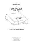
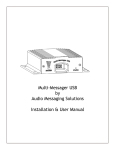
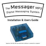
iLink
by
Installation & User Manual
888.664.3366
Mitel On Hold
720 Brooker Creek Blvd., Ste. 215
Oldsmar, FL 34677
888.664.3366
Fax: 727.785.7659
http://mitelonhold.com
[email protected]
Index:
Introduction ........................................................................................................................3
iLink Layout Summary..................................................................................................... 4
Installation ....................................................................................................................... 5
Connectivity Test/Volume Adjustments................................................................................
6-7
Troubleshooting ................................................................................................................ 8 - 9
Indicator & Button Function Charts ...................................................................................10
Warranty & FCC ....................................................................................................................
11
Introduction:
The iLink is an Internet downloadable messaging system utilizing state-of-the-art MPEG compression to achieve truly
stunning near-CD quality audio storage and playback. All unit management and audio downloads are accomplished by your
dealer using a special controller software suite. When an update is needed your dealer connects to the iLink via your highspeed Internet connection and digitally transfers the MP3 audio files and configuration settings you need. Changes can be
initiated on demand, scheduled from minutes to weeks, or the iLink can be instructed to connect automatically and load new
audio.
Unpacking and Inspection:
Before you begin installation, unpack and verify you have all the correct parts.
(1) iLink
(1) 12VDC @ 500mA power supply
(1) Ethernet cable
(1) RCA to RCA cable
(1) RCA to 3.5mm adapter
(1) Wall mount bracket
(2) Wall mount screws
(1) Instruction manual and software utilities on CD
If you are missing any of these parts STOP and call your dealer.
3
iLink Layout Summary:
Front of Unit
888.664.3366
CHANNEL A & B - Depending upon the MODE these multi-color LED’s will indicate unit status or volume
control settings.
VOLUME - The primary function of these buttons is to control the output volume of the iLink as well as the
BGM feedthrough level. The secondary function of these is to initiate a forced connection back to the dealers
server as well as resetting the system.
MODE - This button places the iLink in different configuration modes that control server connection, unit reset,
formatting and volume control functions.
Rear of Unit
LAN - This jack connects to the local Ethernet that allows the iLink connectivity to the Internet. The jack also has
two built in LEDs that report back network activity and speed status.
CHANNEL A or B (IN) - This signal level jack allows an external BGM (Background Music) source to be fed
through the iLink unit.
CHANNEL A or B (OUT) - This jack connects to a phone systems MOH input or a PA amplifier.
8Ω or 600 - This switch changes the output impedance of the CHANNEL A or B (OUT) jack.
POWER - Use this switch to turn the unit ON and OFF.
12VDC - This is where the supplied 12VDC @ 500mA power pack is connected.
4
Installation :
Step 1: Wall or shelf mount the unit. Rubber feet, a wall bracket and screws are supplied in the accessory kit.
Step 2: Verify the power switch on rear of unit is set to OFF. Attach the included power pack to a wall or power
strip receptacle, then attach the other end to the jack on the rear of the unit labeled 12VDC.
Step 3: If connecting unit to an amplifier make sure it is turned OFF for this part of the installation.
Step 4: Connect a RCA cable (supplied in the accessory kit) to the CHANNEL A (OUT) jack on the rear of the
unit. Connect the other end of the RCA cable to a phones MOH port, PA amplifier or speaker. For dual output
applications follow the same procedure for the CHANNEL B (OUT).
Step 5: (Optional) For messaging only applications the existing BGM (Background Music) can be fed through
the iLink. Connect the audio source to the CHANNEL A or B (IN) jack(s) on the rear of the unit. This jack must
only be fed signal level audio - ANY AMPLIFIED AUDIO WILL DAMAGE THE UNIT.
Step 6: Connect an Ethernet cable (supplied in the accessory kit) to the LAN jack on the rear of the unit. Connect
the other end to a 10/100 speed switch or hub.
(Optional)
To MOH or PA
(Optional)
To BGM Source
To MOH or PA
(Optional)
To BGM Source
To Switch or Hub
Wiring Diagram
5
Connectivity Test:
Step 1: Turn the power switch to ON while holding in the DOWN VOLUME button for 5 seconds.
888.664.3366
Step 2: The CHANNEL A and CHANNEL B LEDs should both BLINK ORANGE while trying to connect to
server, once connected both LED’s should be SOLID ORANGE.
888.664.3366
Step 3: After successful connection and download the LEDs (depending upon which CHANNELS are in use)
will change to SOLID or FLASHING GREEN. This process can take anywhere from seconds to hours depending
upon the size of download.
If this step fails try to power cycle the unit before using the troubleshooting guide or calling your dealer.
Stored Audio & BGM Feedthrough Level Adjustments:
Step 1: Verify CHANNEL A or B (OUT) is connected to either a phone’s MOH port, PA amplifier or speaker.
and/or
Step 2: While the CHANNEL LED is SOLID GREEN check the audio level of the device connected to the
corresponding OUT jack of the iLink.
Step 3: Depending upon the device the 600Ω/8Ω switch may need to be pushed to better match the impedance of
the device the iLink is driving.
Step 4: To adjust the stored audio output level press the MODE switch until the LEDs match the chart below.
Once they match the chart below then the VOLUME UP and DOWN buttons can be used to adjust the volume.
If no activity is seen after 60 seconds the unit LEDs will return to normal operation.
Adjust CHANNEL “A” volume
Adjust CHANNEL “B” volume
6
“A” LED
SOLID GREEN
OFF
“B” LED
OFF
SOLID GREEN
STOP! If this does not require a BGM feedthrough then installation is complete!
Step 5: Verify CHANNEL A or B (IN) is connected to the BGM source.
and/or
Step 6: To adjust the BGM feedthrough output level press the MODE switch until the LEDs match the chart
below. Once they match the chart below then the VOLUME UP and DOWN buttons can be used to adjust the
volume. If no activity is seen after 60 seconds the unit LEDs will return to normal operation.
Adjust CHANNEL “A “ BGM volume
Adjust CHANNEL “B” BGM volume
“A” LED
“B” LED
FLASHING GREEN
OFF
OFF
FLASHING GREEN
If this step fails see the troubleshooting guide or call your dealer before continuing.
INSTALLATION COMPLETE
7
Connectivity Troubleshooting:
Step 1: Verify the iLink has been assigned an address by the network.
a. Place the “Documentation and Utilities” CD on a computer on the local network.
b. Browse the CD and run the NTL Studio Utilities program.
c. Click on the “Scan Network” button. Any iLink units on the local network will be displayed.
d. If iLink units MAC and IP address are displayed the skip to Step 3, otherwise continue to Step 2.
Step 2: Manually assign a Static IP address to the iLink.
a. Using the same application as the previous step, click on the “Assign IP” button.
b. In the pop-up screen enter the MAC found on the bottom label of the iLink.
c. Assign a Static IP address as well as the subnet mask and gateway of local network.
d. Make sure DHCP is not checked.
e. Click “OK”
f. Retry the “Connectivity Test” - If test fails continue to next troubleshooting step.
8
Step 3: Verify the iLink has been assigned at least one Connect-Back address.
a. Open a web browser and type the DHCP assigned or manually assigned Static IP address. If the NTL Studio Utilities program is still open, then the “Configure IP” button can be clicked for the same result.
Example:
b. The unit’s built in web application will launch and display the current system settings.
c. Inspect the “Connect-Back Settings” - there should be at least one IP address assigned.
Connect-Back Settings
Connect-Back #1
71.181.88.130
Connect-Back #2
0.0.0.0
Connect-Back #3
0.0.0.0
Connect-Back #4
0.0.0.0
d. If all of these fields are blank then contact your dealer for assistance in entering this information.
e. If at least one field has an IP address then continue to next step.
Step 4: Verify iLink can communicate with your dealer’s server.
a. Run the NTL Studio Utilities program from the CD.
b. Enter the Connect-Back Server IP Address (This is the address from the previous step).
c. Click on the “Test Connect-Back Server” button.
d. The status bar on the bottom of program will display a PASS or FAIL.
e. PASS will signify that the unit seems to be setup correctly on the network.
f. FAIL will signify that a firewall or other security setting is blocking traffic to the unit and that the
network administrator or dealer will need to get involved.
9
Front LED Indicators
Action
Nothing Playing/No Schedules
Playing Audio
Scheduled Mode
Attempting Server Connection
Connected to Server
Adjust CHANNEL “A” volume
Adjust CHANNEL “B” volume
Adjust CHANNEL “A” BGM volume
Adjust CHANNEL “B” BGM volume
Formatting
CHANNEL “A” LED
SOLID RED
SOLID GREEN
FLASHING GREEN
FLASHING ORANGE
SOLID ORANGE
SOLID GREEN
OFF
FLASHING GREEN
OFF
CHANNEL “B” LED
SOLID RED
SOLID GREEN
FLASHING GREEN
FLASHING ORANGE
SOLID ORANGE
OFF
SOLID GREEN
OFF
FLASHING GREEN
GREEN → ORANGE→ RED
GREEN → ORANGE→ RED
Rear LAN LED Indicators
Yellow
Action
No Link
10 Mbps
100 Mbps
Green
Action
No Activity
Half-Duplex
Full-Duplex
LED
OFF
FLASHING
SOLID
LED
OFF
FLASHING
SOLID
Front Buttons
Action
Volume Control Settings1
Forced Connect-Back to Server
Reset Unit2
Complete Reformat of Unit3
1
10
▲
Hold on Power Up
Hold on Power Up
▼
Hold on Power Up
Hold on Power Up
Hold on Power Up
MODE
Push and Release
Hold on Power Up
.
Local volume control must be enabled by dealer for this function to work. 2 All unit settings are lost EXCEPT IP settings. 3 All unit settings are lost and returns unit back to factory default settings
Limited Warranty
TERMS: Mitel warrants to the original purchaser (“Buyer”) that the Product sold is free from defects in material and workmanship
at the time of purchase. The warranty period begins at the time of Product’s original purchase by the first end-user. The warranty
applies for five (5) year from the original date of purchase, or as long as the product is owned by the original purchaser, whichever
comes first. Included in the warranty are parts and labor. Buyer must provide written notice to Mitel of any defective part or
conditions within the warranty period. If the defect is not the result of improper use, service, maintenance or installation, and if the
equipment has not been otherwise damaged or modified after shipment, Mitel or its authorized representative shall either replace or
repair the defective Product at Mitel’s option. No credit shall be allowed for work performed by Buyer or unauthorized parties. Outof-warranty repairs are invoiced at the current hourly rate plus the cost of parts, shipping and handling. In the event that the product
serial number is missing or has been tampered with in any way, the foregoing warranty is void and without effect and Mitel shall have
no liability whatsoever on account of defects to such product.
LIMITATIONS: Except as stated above, there are no warranties, express or implied, that extend beyond the specifications for the
product. Mitel expressly disclaims any warranty, express or implied, that equipment sold hereunder is of merchantable quality or
that it can be used, or is fit for any particular purpose. Buyer purchases and accepts equipment solely on the basis of the warranty
here in above expressed. Under no circumstances shall Mitel be liable by virtue of this warranty or otherwise for any special indirect,
secondary or consequential damages to any person or property arising out of the use or inability to use the product.
REPAIRING OR REPLACING PRODUCT: Buyer may obtain the repair or replacement of any eligible part or equipment
covered under this warranty through a Nel-Tech Labs dealer only. Buyer is responsible for all shipping and handling charges in
connection with the performance of this warranty. Products returned to Mitel must be securely packaged to prevent damage in
transit, freight prepaid, and insured for replacement value. A return authorization number assigned byMitel must be clearly marked
on the outside of the shipping container. Proof of purchase must accompany shipment. Items delivered to Mitel without a return
authorization clearly marked on the outside of the shipping container, and/or without proof of purchase is refused.
COPYRIGHT NOTICE: The Mitel iLink is strictly used for licensed content only. Use of copyrighted content is illegal and NelTech Labs, Inc. takes no responsibility for that action.
FCC Part 15 : This equipment has been tested and found to comply within the limits for a Class A digital device, pursuant to Part
15 of the FCC rules. These limits are designed to provide reasonable protection against harmful interference when the equipment is
operated in a commercial environment. This equipment generates, uses and can radiate radio frequency energy and, if not installed
and used in accordance with the instruction manual, may cause harmful interference to radio communications. Operation of the
equipment in a residential area is likely to cause harmful interference in which case the user will be required to correct interference at
his own expense. In order to maintain compliance with FCC regulations shielded cables must be used with this equipment. Operation
with non-approved equipment or unshielded cables is likely to result in interference to radio & television reception.
Changes or modifications not expressly approved by Mitel could void the users’ authority to operate the equipment.
IC ES 003 : This Class A digital apparatus complies with Canadian ICES-003 C et appareil numérique de la classe A est conform e
à la norme NMB-003 du Canada.
CE CONFORMITY : The Mitel iLink conforms with the following standards, in accordance with the EU Safety, EMC Emissions,
& EMC Immunities : EN 60950-1:2001, EN 55022:1998 for Class A, EN 55024:1998 + A1:2001 + A2:2003, EN 61000-4-2:1995 +
A1:1998, EN 61000-4-3:1995, EN 61000-4-4:1995, EN 61000-4-5:1995, EN 61000-4-6:1996, EN 61000-5-11:1994.
11
Nel-Tech Labs, Inc.
4 Ash Street Extension
Derry, NH 03038
1.800.344.4685
www.nel-techlabs.com
Rev. C - 07/08
Copyright © 1984 - 2008 by Nel-Tech Labs, Inc.