1
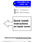
TELink 700 FLASH by INSTALLATION AND OPERATION MANUAL Attention: A telco line surge protector should be used in series with the line connected to this unit. Please leave this manual with the unit after installation Important warranty information enclosed Audio Messaging Solutions, LLC 720 Brooker Creek Blvd., Ste. 215 Oldsmar, FL 34677 800.584.HOLD (4653) Fax: 727.785.7659 http://onholdbusiness.com [email protected] TELink 700 FLASH 04/2009 FCC Notice WARNING: This equipment has been tested and found to comply with the limits for a Class A digital device pursuant to Part 15 of FCC Rules. These limits are designed to provide reasonable protection against harmful interference when this equipment is operated in a commercial environment. This equipment generates, uses, and can radiate radio frequency energy and, if not installed and used in accordance with the instruction manual, may cause harmful interference to radio communications. Operation of this equipment in a residential area is likely to cause harmful interference in which case the user will be required to correct the interference at his/her own expense. This digital apparatus does not exceed the Class A limits for radio noise emissions from digital apparatus set out in the Radio Interference Regulations of the Canadian Department of Communications. Le présent appareil numérique n'émet pas de bruits radioélectriques dépassant les limites applicables aux appareils numériques de la Class A prescrites dans le Règlement sur le brouillage radioélectrique édicté par le ministère des Communications du Canada. Limited Warranty{tc \l1 "LIMITED WARRANTY} TERMS: Audio Messaging Solutions (“AMS”) warrants to the original purchaser ("Buyer") that the Product sold is free from defects in material and workmanship at the time of purchase. The warranty extends five (5) years from the date of original purchase and covers parts and labor. Buyer must provide written notice to AMS within the warranty period of any defective part or conditions. If the defect is not the result of improper use, service, maintenance or installation, and if the equipment has not been otherwise damaged or modified after shipment, AMS or its authorized representative shall either replace or repair the defective Product at AMS's option. No credit shall be allowed for work performed by Buyer or unauthorized parties. Out-of-warranty repairs will be invoiced at the current hourly rate plus the cost of parts, shipping and handling. IN THE EVENT THAT THE PRODUCT SERIAL NUMBER IS MISSING OR HAS BEEN TAMPERED WITH IN ANY WAY, THE FOREGOING WARRANTY IS VOID AND WITHOUT EFFECT AND AMS SHALL HAVE NO LIABILITY WHATSOEVER ON ACCOUNT OF DEFECTS TO SUCH PRODUCT. LIMITATIONS: EXCEPT AS STATED ABOVE, THERE ARE NO WARRANTIES, EXPRESSED OR IMPLIED, THAT EXTEND BEYOND THE SPECIFICATIONS FOR THE PRODUCT. AMS EXPRESSLY DISCLAIMS ANY WARRANTY, EXPRESSED OR IMPLIED, THAT EQUIPMENT SOLD HEREUNDER IS OF MERCHANTIABLE QUALITY OR THAT IT CAN BE USED, OR IS FIT FOR ANY PARTICULAR PURPOSE. BUYER PURCHASES AND ACCEPTS EQUIPMENT SOLELY ON THE BASIS OF THE WARRANTY HEREINABOVE EXPRESSED. UNDER NO CIRCUMSTANCES SHALL AMS BE LIABLE BY VIRTUE OF THIS WARRANTY OR OTHERWISE FOR ANY SPECIAL, INDIRECT, SECONDARY OR CONSEQUENTIAL DAMAGES TO ANY PERSON OR PROPERTY ARISING OUT OF THE USE OR INABILITY TO USE THE PRODUCT. REPAIRING OR REPLACING PRODUCT: Buyer may obtain the repair or replacement of any eligible part or equipment covered under this warranty through AMS only. Buyer is responsible for all shipping and handling charges in connection with the performance of this warranty. Products returned to AMS must be securely packaged to prevent damage in transit, freight prepaid, and insured for replacement value. A return authorization number assigned by AMS must be clearly marked on the outside of the shipping container. Proof of purchase must accompany shipment. Items delivered to AMS without a return authorization clearly marked on the outside of the shipping container, and/or without proof of purchase will be refused. Please contact AMS at the address and phone number below to receive a return authorization number and to arrange for the repair or replacement of a flawed part covered by this warranty. Please indicate the Product's serial number in all correspondence. an authorization number will not be issued in the absence of a serial number. Audio Messaging Solutions, 720 Brooker Creek Blvd., Ste. 215, Oldsmar, FL 34677 Phone: (800) 584-4653. Copyright Notice This manual copyright 1993-2009 by Audio Messaging Solutions All rights reserved. No part of it may be copied, photocopied, reproduced, translated, or reduced to any electronic medium or machine-readable form without AMS's prior written consent. Information contained herein is subject to change without prior notification. AMS provides this manual without warranty of any kind, expressed or implied. This user's manual may contain technical and/or typographical errors. Printed in the U.S.A TELink 700 FLASH 2 04/2009 TABLE OF CONTENTS FCC NOTICE ....................................................................................................... 2 LIMITED WARRANTY ......................................................................................... 2 1. SYSTEM DESCRIPTION ............................................................................... 4 2. INSTALLATION .............................................................................................. 5 VOICE LINE AND/OR NIGHT ANSWER INSTALL PROCEDURE ........... 6 DEDICATED LINE INSTALL PROCEDURE .............................................. 7 FAX SHARE INSTALL PROCEDURE ....................................................... 9 FINAL INSTALLATION............................................................................. 11 3. OPTIONAL FEATURES ............................................................................... 12 4. TROUBLESHOOTING ................................................................................. 14 LIST OF TABLES TABLE 1—STATUS LIGHT INDICATIONS....................................................... 11 TABLE 2—NIGHT LIGHT INDICATIONS.......................................................... 13 TABLE 3—TROUBLESHOOTING .................................................................... 14 TELink 700 FLASH 3 04/2009 1. SYSTEM DESCRIPTION{tc \l1 "1. SYSTEM DESCRIPTION} The TELink FLASH is a powerful, simple to use messaging system intended for telephone Messaging On Hold (MOH). Once properly installed, no further interaction from the user is required. Unlike other MOH products, the TELink FLASH is designed to be operated remotely by the MOH provider using a central PC Controller. This feature eliminates the need for tape distribution because all audio information and configuration settings are downloaded over telephone lines. Because the unit uses non-volatile FLASH memory, your audio program is safe from erasure due to power loss for up to 10 years. If power is lost, audio playback resumes automatically once power is restored. This feature eliminates the need for a battery backup system. The TELink FLASH has been designed to accommodate several different installation needs. The standard installation method allows normal access to the telephone line while automatically preventing an unintentional disruption of a communication session between the TELink and the PC Controller. In a typical installation, the unit is installed directly to the incoming telephone line with no other telephone equipment connected prior to the TELink. An installation involving a KSU or PBX may look like what is illustrated below: TELink 700 FLASH 4 04/2009 2. INSTALLATION{tc \l1 "2. INSTALLATION} If your MOH provider included other installation instructions, those instructions should be followed first. There are three installation procedures available, depending on the phone line used. Keep in mind that whichever installation procedure is used, the TELink must always be connected directly to the telephone company input, ahead of any other devices using that line. If you have any questions or require assistance installing the TELink, please contact your MOH provider. TELink 700 FLASH 5 04/2009 VOICE LINE AND/OR NIGHT ANSWER INSTALL PROCEDURE{tc \l2 "INSTALLATION PROCEDURE A} 1. Make sure the power switch on the back of the TELink is in the OFF position. 2. Connect one end of the included modular telephone cable directly to the phone company box for the installation phone number. It is important that this cable is attached to a direct line, prior to any other telephone equipment. The user may need to adapt one end of the modular cable to mate to the incoming phone line. If the TELink is equipped with the Night Answer option, the installation line must be the first line answered by the telephone system. If you are not sure which line this is, check with your local phone company. 3. Connect the other end of the modular cable to the TELCO jack on the back of the TELink. 4. Using another modular telephone cable, connect the PHONE jack on the back of the TELink to the installation phone line's original destination (KSU, PBX, telephone, etc). 5. Set the HI/LO switch on the back of the TELink to the proper position for the telephone system (LO=8 Ω, HI=1K Ω). 6. Connect the TELink's AUDIO OUTPUT jack to the telephone system's MOH input using the included RCA cable. The user may need to adapt the phone system end of this cable to match the MOH input connection on the phone system. 7. Plug the included 12VDC power supply into a normal 110VAC wall outlet. Connect the other end to the 12VDC jack on the back of the TELink. 8. Turn the power switch ON. Turn to page 9 for further instructions. TELink 700 FLASH 6 04/2009 DEDICATED LINE INSTALL PROCEDURE{tc \l2 "INSTALLATION PROCEDURE B} 1. Make sure the power switch on the back of the TELink is in the OFF position. 2. Connect one end of the included modular telephone cable directly to the phone company box for the installation phone number. The user may need to adapt one end of the modular cable to mate to the incoming phone line. 3. Connect the other end of the modular cable to the TELCO jack on the back of the TELink. 4. Using another modular telephone cable, connect the PHONE jack on the back of the TELink to the installation phone line's original destination (KSU, PBX, telephone, etc). 5. Set the HI/LO switch on the back of the TELink to the proper position for the telephone system (LO=8 Ω, HI=1K Ω). 6. Connect the TELink's AUDIO OUTPUT jack to the telephone system's MOH input using the included RCA cable. The user may need to adapt the phone system end of this cable to match the MOH input connection on the phone system. 7. Plug the included 12VDC power supply into a normal 110VAC wall outlet. Connect the other end to the 12VDC jack on the back of the TELink. 8. Turn the power switch ON. Turn to page 9 for further instructions. TELink 700 FLASH 7 04/2009 TELink 700 FLASH 8 04/2009 FAX SHARE INSTALL PROCEDURE{tc \l2 "INSTALLATION PROCEDURE C} 1. Make sure the power switch on the back of the TELink is in the OFF position. 2. Connect one end of the included modular telephone cable directly to the phone company box for the installation phone number. The TELink must be connected before the fax machine. The user may need to adapt one end of the modular cable to mate to the incoming phone line. 3. Connect the other end of the modular cable to the TELCO jack on the back of the TELink. 4. Using another modular telephone cable, connect the PHONE jack on the back of the TELink to the fax machine. 5. Set the HI/LO switch on the back of the TELink to the proper position for the telephone system (LO=8 Ω, HI=1K Ω). 6. Connect the TELink's AUDIO OUTPUT jack to the telephone system's MOH input using the included RCA cable. The user may need to adapt the phone system end of this cable to match the MOH input connection on the phone system. 7. Plug the included 12VDC power supply into a normal 110VAC wall outlet. Connect the other end to the 12VDC jack on the back of the TELink. 8. Set the fax machine to answer on the fewest rings possible (but a minimum of two rings). TELink 700 FLASH 9 04/2009 9. Turn the power switch ON. Turn to page 9 for further instructions. TELink 700 FLASH 10 04/2009 FINAL INSTALLATION{tc \l2 "FINAL INSTALLATION} After installation is complete, a download may be required. Check the STATUS light on the front panel (note: on some units this light is labeled ACTIVE): IF IT IS ON (STEADY): An audio file is present in memory and is currently playing. Download is not required. IF IT IS FLASHING SLOWLY: No audio file is present. Contact your MOH provider. They must call the unit and download audio. IF IT IS FLASHING FAST: The unit is automatically calling the callback number stored in memory to download audio from the PC Controller. This first callback to the PC Controller must be successful in order to validate the callback number. If the first call does not result in contact with the PC Controller, then callback validation has failed and the unit will not call again. In this case, the STATUS light will alternate between a flash fast for one second and no flash for one second. Contact your MOH provider. They may then call the unit and download audio. During communications sessions between the TELink and the PC Controller, the STATUS light flashes fast and the phone line becomes unavailable for incoming and outgoing calls (no dial tone will be present). After a successful download the STATUS light remains on (steady). At this point, call into the phone system and ask to be placed on hold. While listening to the on-hold audio, adjust the volume (if necessary) using the volume UP/DOWN buttons on the front panel. If there is no on-hold audio, verify all connections against the installation procedure used and try again. If there is still no on-hold audio, contact your MOH provider. STATUS (or ACTIVE) Light On Off Flashing Slowly Indication Audio file in memory, currently playing No power to unit or an error has occurred No audio file in memory, phone line free Data session with PC Controller is being Flashing Fast attempted or is in progress Alternating – Fast Flash / No The TELink failed to validate the callback Flash number. Contact your MOH provider. Table 1—Status Light Indications TELink 700 FLASH 11 04/2009 3. OPTIONAL FEATURES{tc \l1 "3. OPTIONAL FEATURES} Your TELink may have optional features which provide additional convenience and functionality. The serial number label on the bottom of the unit indicates which features the unit has. Note that the unit may be equipped with optional features that have not been activated by your MOH provider. CALL ON SCHEDULE (CS) allows the TELink to be programmed to call the PC Controller at a future date and time to automatically download a new audio program. The scheduled callback can be set to a specific time, month, day, and year. The STATUS (or ACTIVE) light flashes fast during a callback. If the unit cannot connect to the PC Controller (for instance, if the line is busy), it will continue calling at seven minute intervals until a connection is made, or until the preprogrammed number of retries has been exhausted. Before CS can operate automatically, the callback telephone number must be validated during initial installation and whenever the callback number is changed by the MOH provider. During validation, the TELink makes one call attempting to establish communications with the PC Controller. If it is successful, the callback features become fully operational. If validation fails, contact your MOH provider. FAX SHARE (FS) allows the TELink to share a phone line with a fax machine, saving the expense of having to install a separate line. In a Fax Share installation, the TELink only answers calls from the PC Controller and does not interfere with incoming or outgoing fax transmissions. The fax machine must be set to answer on two or more rings. Fax Share is standard on most units, although the FS designation may not appear on the serial number label. Fax Share cannot be used together with Night Answer. NIGHT ANSWER (N) provides the capability to store a separate 15, 30, 45, or 60 second night answer message, in addition to the standard MOH message. Before using Night Answer, the MOH provider must enable the feature from the PC Controller and download a standard MOH message and a Night Answer message. When activated (ON), the TELink answers incoming calls, plays the Night Answer message, then hangs up the call. Two Night Answer modes are available: Scheduled - The Night Answer message can be scheduled from the PC Controller to turn on and off automatically once per day, on a sevenday calendar. Sample schedule: Night Answer turns OFF at 9am and ON at 5pm Monday-Friday, with no ON or OFF time scheduled for Saturday and Sunday. Under this schedule, Night Answer is active during non-business hours (5pm-9am) and all weekend long. TELink 700 FLASH 12 04/2009 Manual - Night Answer can be turned ON or OFF on demand by pressing the NIGHT button on the front panel. If a Night Answer schedule is present, this will preempt it. If you manually turn Night Answer ON or OFF, it will remain in that state until you cancel Manual mode (press the NIGHT button again). Then, Night Answer operation will return to Scheduled (if a schedule is present). IMPORTANT: If Night Answer is turned ON manually, you must remember to turn it OFF when you want calls to ring through normally. Until Night Answer is turned OFF, the TELink will continue to answer calls, play the Night Answer message, then hang up. DO NOT forget to turn Night Answer OFF at the desired time. When using Night Answer, it is extremely important that the TELink is installed on the first phone number that the phone system answers. However, because this line is likely to be the most heavily used, the PC Controller may encounter difficulty (busy line) when trying to call the unit. For the same reason, the unit may also have difficulty calling the PC Controller. Therefore, it is recommended that the initial installation and subsequent downloads be scheduled during times when the line is not likely to be in use (during non-business hours). Note that when the TELink answers a call in Night Answer mode, any other calls that come in will not hear the Night Answer message, but will instead be handled normally by the phone system. The NIGHT light on the front of the TELink indicates the current ON/OFF status of the Night Answer feature: NIGHT Light On Off Flashing TELink 700 FLASH Indication Night Answer ON Night Answer OFF Slow flash – Night Answer OFF Fast flash – Night Answer ON Table 2—Night Light Indications 13 04/2009 4. TROUBLESHOOTING{tc \l1 "4. TROUBLESHOOTING} Problem / Symptom Audio output level is too low or too high. TELink does not answer when called by the PC Controller. The telephone line to which the TELink is attached does not work. STATUS (or ACTIVE) light alternates between 1 second flash flash, and 1 second no flash. Possible Solution(s) • Adjust the volume by pressing the UP/DOWN volume switches on the front panel. If the volume level does not change, contact your MOH provider. • Possible impedance mismatch between phone system’s MOH port and the TELink. Try switching the HI/LO switch on the back of the TELink. • The TELink is not connected directly to the telephone company input. • Other telephone devices are connected prior to the TELink. The TELink must be the first device connected to where the telephone line enters the building. • The TELink may be communication with the PC controller. The unit automatically locks its phone line during communications to protect data integrity. Check the STATUS led. If it is flashing fast, the unit is in a data session. • First attempt to call the callback phone number has failed. • If the initial callback validation has failed you will need to contact your MOH provider for further instruction. Table 3—Troubleshooting TELink 700 FLASH 14 04/2009