1
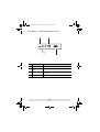
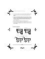
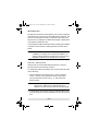
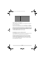
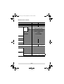
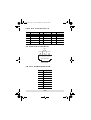
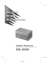
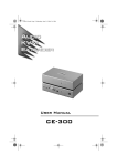
CE252.fm Page 1 Friday, September 15, 2006 12:08 PM User Manual CE-252R/L Read this guide thoroughly and follow the installation and operation procedures carefully in order to prevent any damage to the units and/or any devices that connect to them. This package contains: 1 CE-252L KVM Extender (Local Unit) 1 CE-252R KVM Extender (Remote Unit) 1 User Manual 1 User Guide 2 KVM Cables 2 Power Adapters 2 Rack Mount Kits If anything is damaged or missing, contact your dealer. Copyright © 2006 ATEN® International Co., Ltd. Manual Part No. PAPE -1278 -100G Printing Date: 09/2006 ATEN and the ATEN logo are trademarks of ATEN International Co., Ltd. All rights reserved. All other trademarks are the property of their respective owners. CE252.fm Page 2 Friday, September 15, 2006 12:08 PM Note: This equipment has been tested and found to comply with the limits for a Class B digital device, pursuant to Part 15 of the FCC Rules. These limits are designed to provide reasonable protection against harmful interference in a residential installation. This equipment generates, uses and can radiate radio frequency energy, and if not installed and used in accordance with the instruction manual, may cause interference to radio communications. However, there is no guarantee that interference will not occur in a particular installation. If this equipment does cause harmful interference to radio or television reception, which can be determined by turning the equipment off and on, the user is encouraged to try to correct the interference by one or more of the following measures: Reorient or relocate the receiving antenna; Increase the separation between the equipment and receiver; Connect the equipment into an outlet on a circuit different from that which the receiver is connected; Consult the dealer or an experienced radio/television technician for help. This product is RoHS compliant. CE252.fm Page 3 Friday, September 15, 2006 12:08 PM OVERVIEW The CE-252R/L offers local and remote access to your KVM installation. Both (local and remote) KVM extenders support PS/2 consoles and can be located up to 300 m (1000 feet) apart. You can reliably manage a large number of computers via a KVM switch. Additional computers can also be connected to the remote KVM extender. The CE-252R/L also features Automatic Gain Control, which compensates signal strength as the distance between the local and remote KVM extenders varies (over Cat 5 cables). This translates into high resolution video (up to 2048 x 1536) at a lower cost. The CE-252R/L uses a custom ASIC to ensure the utmost reliability and compatibility. This technology comprises automatic distance sensing and signal strength (gain) adjustment. Setup is easy - simply connect the computer system box (or KVM switch) and Local Console to the CE-252 Local Unit; run a Cat. 5 cable to the CE-252 Remote Unit (up to 300 meters away); finally plug the Remote Console into the Remote Unit. -3- CE252.fm Page 4 Friday, September 15, 2006 12:08 PM Features Built-in ASIC for greater reliability and compatibility Cat.5 cable to connect the local and remote units up to 300 meters apart Dual console operation – control the system from both the local and remote consoles Push button selection – sequential selection between local and auto mode High resolution video – up to 1024 x 768 @ 60Hz, 300 meters VGA, SVGA, and multisync monitor support Local monitor supports DDC; DDC2; DDC2B Two gain control modes provided for the sharpest video quality – adjustable (manual) or automatic Adjustable gain control – manually adjusts signal strength Automatic gain control – automatically adjusts signal strength Easy to install – no software required – connecting cables to the devices is all it takes -4- CE252.fm Page 5 Friday, September 15, 2006 12:08 PM System Requirements Consoles Two VGA, SVGA, or Multisync monitors capable of the highest resolution that you will be using on any computer in the installation Two PS/2 style keyboards Two PS/2 style mice Note: If you connect a DDC type monitor to the Local Unit, the monitor that connects to the Remote Unit must be able to support the highest video resolution that the DDC monitor can provide. Computers The following equipment must be installed on each computer that is to be connected to the system: A VGA, SVGA, or Multisync card A 6-pin mini-DIN mouse port A 6-pin mini-DIN Keyboard port Cables Although it is possible to use standard KVM cables to link computers with PS/2 type keyboard and mouse ports to the CE-252R/L, for optimal signal integrity ATEN recommends using the KVM Cables provided with this package. For best performance, use Category 5 (or better) cables to connect the CE-252 Local and Remote Units. -5- CE252.fm Page 6 Friday, September 15, 2006 12:08 PM Hardware Overview CE-252 Local Front View 1 2 3 4 # Description Function 1 CPU Port (KVM Port) Section KVM cable connector 2 Local LED On: local console active Off: remote console active Flash: neither console active 3 Remote LED On: remote console active Off: local console active Flash: neither console active 4 Push Button Press to choose the operating mode: Local: only local console controls system Auto: both consoles control system -6- CE252.fm Page 7 Friday, September 15, 2006 12:08 PM CE-252 Remote Front View 1 2 5 6 3 4 # Description 1 CPU Port (KVM Port) Section KVM cable connector Function 2 Manual Gain Control Use a flathead screwdriver or other similar object to manually adjust the signal gain 3 Auto/Manual Gain Selection Switch Auto: the unit automatically adjusts the signal gain Manual: signal gain is set using the Manual Gain Control 4 Hotkey Selection Switch Select CTRL + CTRL or SCROLL LOCK + SCROLL LOCK as the hotkey. (When changing hotkey settings, you must disconnect and then reconnect the Remote Unit's power adapter cable for the new settings to take effect.) 5 Local LED On: remote console is accessing local PC or is able to access local PC Off: remote console is not accessing local PC Flash: connection to the local PC failed 6 Remote LED On: remote console is accessing remote PC Off: remote console is not accessing remote PC -7- CE252.fm Page 8 Friday, September 15, 2006 12:08 PM CE-252L / CE-252R Rear View 1 3 4 2 # Description Function 1 Power Jack The AC Power Adapter cable connects here 2 Keyboard/Mouse Ports PS/2 ports for keyboard (purple) and mouse (green) 3 Remote I/O The Category 5 cable that connects the two units plugs in here 4 Monitor Port The monitor connects to this port -8- CE252.fm Page 9 Friday, September 15, 2006 12:08 PM Hardware Installation Before you Begin 1. Ensure that all equipment to be connected is powered off. 2. Make sure that all devices you will be connecting up are properly grounded. 3. Unplug the power cords of any computers that have the Keyboard Power On function. Setting up the CE-252 is simply a matter of plugging in the cables. Refer to the installation diagram on the following page (the numbers in the diagram correspond to the numbered steps) and do the following: 1. Connect the local console devices (mouse, keyboard and monitor) to the ports on the rear of the Local Unit (CE-252L). 2. Plug the provided KVM cable into the appropriate connector on the front of the CE-252L, then plug the connectors on the other end of the KVM cable into the appropriate ports on the computer system (or Console section of the KVM switch - if you are using one). Each connector is marked with an identifying icon. 3. Connect one end of a Category 5 twisted pair cable to the Remote I/O port on the CE-252L, then plug the other end of the Category 5 twisted pair cable into the Remote I/O port on the CE-252R. 4. Connect one of the provided power adapters into an AC source, then connect the adapter's power cable to the Power Jack on the rear of the CE-252L. -9- CE252.fm Page 10 Friday, September 15, 2006 12:08 PM 5. Connect the remote console devices (mouse, keyboard and monitor) to the ports on the rear of the Remote Unit (CE252R). 6. Plug the provided KVM cable into the appropriate connector on the front of the CE-252R, then plug the connectors on the other end of the KVM cable into the appropriate ports on the computer system (or Console section of the KVM switch - if you are using one). Each connector is marked with an identifying icon. 7. Connect the other provided power adapter into an AC source, then connect the adapter's power cable to the Power Jack on the CE-252R. Installation Diagram Remote Front View Local Front View 2 6 KVM cable Local PC Remote PC Local Rear View Remote Rear View Cat. 5 cable 3 4 7 Power adapter cable 1 1 5 - 10 - 5 CE252.fm Page 11 Friday, September 15, 2006 12:08 PM Operation By default, the Remote Console allows you to access computers connected to the Local Unit (via the KVM switch). Moreover, the Remote Console offers access to computers connected to the Remote Unit. For example, an additional computer or KVM switch connected to the Remote Unit. The CE-252R/L KVM Extender features the following two flexible computer access methods: Hotkey Operation and Auto Scan Mode. Note: Before using the Remote Console, verify the Hardware installation is complete. See “Hardware Installation” on page 9. Hotkey operation and Auto Scan mode are only available to Remote Console (Remote Unit) users. Hotkey Operation Hotkeys offer convenient switching between the Local and Remote Units from the Remote Console. To change the KVM focus between the Local and Remote Units do the following: 1. From the Remote Unit, select CTRL + CTRL or SCROLL LOCK + SCROLL LOCK (Hotkey selection slide switch, see CE-252 Remote Front View, p. 7). This will set the desired hotkey. Note: When connecting an additional KVM switch to the Remote Unit, make sure the selected hotkey is different from the one being used to control the KVM. 2. At the Remote Unit console, press the selected hotkey twice. This will change the KVM focus between the local and remote PCs. - 11 - CE252.fm Page 12 Friday, September 15, 2006 12:08 PM Auto Scan Mode (ASM) The Auto Scan feature automatically toggles the KVM focus between the Local and Remote Units at regular intervals. As a result, any computers connected to each can be monitored without user intervention. The default time interval is 5 seconds. To invoke Auto Scan Mode do the following: Press and release the Left Shift key; then press and release the Right Shift key: [Left Shift] [Right Shift] Once scanning begins, it continues until you press the [Spacebar] to exit Auto Scan Mode. The port that was currently active at the time scanning stopped remains active. Note: While Auto Scan Mode is in effect, ordinary keyboard and mouse functions are suspended. You must exit Auto Scan Mode by pressing the [Spacebar] in order to regain normal control of their use. Changing the Scan Interval If you wish, before you invoke Auto Scanning you can change the amount of time Auto Scan stops at each port. To do so, use the following Hotkey combination (press and release the keys one at a time): [Left shift] [Right shift] [n] Where n represents a number from 1 to 4 that specifies the desired scan interval time, as shown in the table on the following page: - 12 - CE252.fm Page 13 Friday, September 15, 2006 12:08 PM n Scan Interval 1 3 secs 2 5 secs 3 10 secs 4 20 secs Using Gain Controls After installing the CE-252R/L, you can adjust the strength of the video signal (Gain). There are two available Gain controls: Automatic and Manual. Select the Automatic Gain slide switch on the Remote Unit to let CE-252R/L adjust the video signal strength. Otherwise, to adjust the gain manually, select the Manual Gain slide switch, then turn the Video Gain Control knob left or right. Accessing Local Computers The Local/Auto button located on the Local Unit allows users to restrict the access to the KVM switch connected to it. Pushing the Local button will block access from the remote console to the local computers (only the Local Console has access). Selecting Auto will allow access from both consoles (Local and Remote Consoles). - 13 - CE252.fm Page 14 Friday, September 15, 2006 12:08 PM Specifications Function CE-252L CE-252R Computer Connections 1 Port Selection Connectors 1 x Pushbutton Console Port Keyboard Video 1 x HDB-15 Female (Blue) Mouse 1 x 6-pin Mini-DIN Female (Green) KVM Port 1 x SPHD-15 Female (Yellow) Link 1 x RJ-45 Power adapter LEDs Knobs Switches Emulation 1 x DC Jack (Black) Local 1 (green) Remote 1 (green) Video Gain Control N/A 1 Auto / Manual Gain N/A 1 x 2 Slide Hotkey Selection N/A 1 x 2 Slide Keyboard / Mouse PS/2 Video 2048 x 1536 @60Hz, DDC2B Power Consumption 1600x1200 @ 150 m. 1024x768 @ 300 m. DC 5.3V, 2.6W Environment Operating Temperature 0°–50°C Storage Temperature Physical Properties N/A 1 x 6-pin Mini-DIN Female (Purple) -20°–60°C Humidity 0–90% RH, Non-condensing Housing Metal Weight 0.4kg Dimensions (L x W x H) 13 x 7.7 x 4.5 cm - 14 - 20 x 7.7 x 4.5 cm CE252.fm Page 15 Friday, September 15, 2006 12:08 PM VGA Pin Assignments Pin Signal Pin Signal Pin Signal 1 Red Video 6 2 Green Video 7 Analog Ground 11 ID0 Analog Ground 12 ID1 3 Blue Video 8 4 ID2 9 Analog Ground 13 Horizontal Sync NC 14 Vertical Sync 5 Ground 10 Ground 15 ID3 TP WIRING DIAGRAM PAIR 3 PAIR 2 PAIR 1 PAIR 4 1 2 3 4 5 6 7 8 W-O O W-G Bl W-Bl G W-Br Br JACK POSITIONS T568B AT&T 258A TP PIN ASSIGNMENTS Pin Assignment 1 V OUT B 2 /V OUT B 3 V OUT G 4 V OUT R 5 /V OUT R 6 /V OUT G 7 /DO 8 DO - 15 - CE252.fm Page 16 Friday, September 15, 2006 12:08 PM Getting Help If you need to contact ATEN technical support with a problem, visit our website at www.aten.com. Limited Warranty IN NO EVENT SHALL THE DIRECT VENDOR'S LIABILITY EXCEED THE PRICE PAID FOR THE PRODUCT FROM THE DIRECT, INDIRECT, SPECIAL, INCIDENTAL OR CONSEQUENTIAL DAMAGES RESULTING FROM THE USE OF THE PRODUCT, DISK OR ITS DOCUMENTATION. The direct vendor makes no warranty or representation, expressed, implied, or statutory with respect to the contents or use of this documentation, and specially disclaims its quality, performance, merchantability, or fitness for any particular purpose. The direct vendor also reserves the right to revise or update the device or documentation without obligation to notify any individual or entity of such revisions, or update. For further inquires please contact your direct vendor. - 16 -