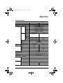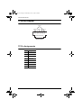
1
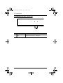
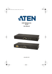
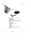
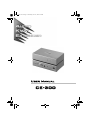
ce300-v3.book Page i Wednesday, June 21, 2006 2:45 PM User Manual CE-300 ce300-v3.book Page ii Wednesday, June 21, 2006 2:45 PM CE-300 User Manual FCC Information Note: This equipment has been tested and found to comply with the limits for a Class B digital device, pursuant to Part 15 of the FCC Rules. These limits are designed to provide reasonable protection against harmful interference in a residential installation. This equipment generates, uses and can radiate radio frequency energy, and if not installed and used in accordance with the instruction manual, may cause interference to radio communications. However, there is no guarantee that interference will not occur in a particular installation. If this equipment does cause harmful interference to radio or television reception, which can be determined by turning the equipment off and on, the user is encouraged to try to correct the interference by one or more of the following measures: Reorient or relocate the receiving antenna; Increase the separation between the equipment and receiver; Connect the equipment into an outlet on a circuit different from that which the receiver is connected; Consult the dealer or an experienced radio/television technician for help. RoHS This product is RoHS compliant. ii ce300-v3.book Page iii Wednesday, June 21, 2006 2:45 PM CE-300 User Manual User Notice All information, documentation, and specifications contained in this manual are subject to change without prior notification by the manufacturer. The manufacturer makes no representations or warranties, either expressed or implied, with respect to the contents hereof and specifically disclaims any warranties as to merchantability or fitness for any particular purpose. Any of the manufacturer's software described in this manual is sold or licensed `as is'. Should the programs prove defective following their purchase, the buyer (and not the manufacturer, its distributor, or its dealer), assumes the entire cost of all necessary servicing, repair and any incidental or consequential damages resulting from any defect in the software. The manufacturer of this system is not responsible for any radio and/or TV interference caused by unauthorized modifications to this device. It is the responsibility of the user to correct such interference. The manufacturer is not responsible for any damage incurred in the operation of this system if the correct operational voltage setting was not selected prior to operation. PLEASE VERIFY THAT THE VOLTAGE SETTING IS CORRECT BEFORE USE. iii ce300-v3.book Page iv Wednesday, June 21, 2006 2:45 PM CE-300 User Manual Safety Instructions General Read all of these instructions. Save them for future reference. Follow all warnings and instructions marked on the device. Do not place the device on any unstable surface (cart, stand, table, etc.). If the device falls, serious damage will result. Do not use the device near water. Do not place the device near, or over, radiators or heat registers. The device cabinet is provided with slots and openings to allow for adequate ventilation. To ensure reliable operation, and to protect against overheating, these openings must never be blocked or covered. The device should never be placed on a soft surface (bed, sofa, rug, etc.) as this will block its ventilation openings. Likewise, the device should not be placed in a built in enclosure unless adequate ventilation has been provided. Never spill liquid of any kind on the device. Unplug the device from the wall outlet before cleaning. Do not use liquid or aerosol cleaners. Use a damp cloth for cleaning. The device should be operated from the type of power source indicated on the marking label. If you are not sure of the type of power available, consult your dealer or local power company. The device is equipped with a 3-wire grounding type plug. This is a safety feature. If you are unable to insert the plug into the outlet, contact your electrician to replace your obsolete outlet. Do not attempt to defeat the purpose of the grounding-type plug. Always follow your local/national wiring codes. Do not allow anything to rest on the power cord or cables. Route the power cord and cables so that they cannot be stepped on or tripped over. If an extension cord is used with this device make sure that the total of the ampere ratings of all products used on this cord does not exceed the extension cord ampere rating. Make sure that the total of all products plugged into the wall outlet does not exceed 15 amperes. To help protect your system from sudden, transient increases and decreases in electrical power, use a surge suppressor, line conditioner, or un-interruptible power supply (UPS). iv ce300-v3.book Page v Wednesday, June 21, 2006 2:45 PM CE-300 User Manual Position system cables and power cables carefully; Be sure that nothing rests on any cables. When connecting or disconnecting power to hot-pluggable power supplies, observe the following guidelines: Install the power supply before connecting the power cable to the power supply. Unplug the power cable before removing the power supply. If the system has multiple sources of power, disconnect power from the system by unplugging all power cables from the power supplies. Never push objects of any kind into or through cabinet slots. They may touch dangerous voltage points or short out parts resulting in a risk of fire or electrical shock. Do not attempt to service the device yourself. Refer all servicing to qualified service personnel. If the following conditions occur, unplug the device from the wall outlet and bring it to qualified service personnel for repair. The power cord or plug has become damaged or frayed. Liquid has been spilled into the device. The device has been exposed to rain or water. The device has been dropped, or the cabinet has been damaged. The device exhibits a distinct change in performance, indicating a need for service. The device does not operate normally when the operating instructions are followed. Only adjust those controls that are covered in the operating instructions. Improper adjustment of other controls may result in damage that will require extensive work by a qualified technician to repair. v ce300-v3.book Page vi Wednesday, June 21, 2006 2:45 PM CE-300 User Manual Rack Mounting Before working on the rack, make sure that the stabilizers are secured to the rack, extended to the floor, and that the full weight of the rack rests on the floor. Install front and side stabilizers on a single rack or front stabilizers for joined multiple racks before working on the rack. Always load the rack from the bottom up, and load the heaviest item in the rack first. Make sure that the rack is level and stable before extending a device from the rack. Use caution when pressing the device rail release latches and sliding a device into or out of a rack; the slide rails can pinch your fingers. After a device is inserted into the rack, carefully extend the rail into a locking position, and then slide the device into the rack. Do not overload the AC supply branch circuit that provides power to the rack. The total rack load should not exceed 80 percent of the branch circuit rating. Ensure that proper airflow is provided to devices in the rack. Do not step on or stand on any device when servicing other devices in a rack. vi ce300-v3.book Page vii Wednesday, June 21, 2006 2:45 PM CE-300 User Manual Package Contents This package consists of: 1 CE-300L Audio KVM Extender (Local Unit) 1 CE-300R Audio KVM Extender (Remote Unit) 1 Custom KVM Cable (1.8 m) 2 Power Adapters 2 Rack Mounting Kits 1 Firmware Upgrade Cable 1 User Manual 1 Quick Start Guide Check to make sure that all the components are present and that nothing got damaged in shipping. If you encounter a problem, contact your dealer. Read this manual thoroughly and follow the installation and operation procedures carefully to prevent any damage to the unit, and/or any of the devices connected to it. * Features may have been added to the CE-300 since this manual was printed. Please visit our website to download the most up to date version of the manual. © Copyright 2006 ATEN® International Co., Ltd. Manual Part No. PAPE-XXXX-XXXX Printing Date: 06/2006 ATEN and the ATEN logo are registered trademarks of ATEN International Co., Ltd. All rights reserved. All other brand names and trademarks are the registered property of their respective owners. vii ce300-v3.book Page viii Wednesday, June 21, 2006 2:45 PM CE-300 User Manual Contents FCC Information . . . . . . . . . . . . . . . . . . . . . . . . . . . . . . . . . . . . . . . . . . . . . ii User Notice . . . . . . . . . . . . . . . . . . . . . . . . . . . . . . . . . . . . . . . . . . . . . . . . . iii Safety Instructions . . . . . . . . . . . . . . . . . . . . . . . . . . . . . . . . . . . . . . . . . . .iv General . . . . . . . . . . . . . . . . . . . . . . . . . . . . . . . . . . . . . . . . . . . . . . . . .iv Rack Mounting . . . . . . . . . . . . . . . . . . . . . . . . . . . . . . . . . . . . . . . . . . .vi Package Contents . . . . . . . . . . . . . . . . . . . . . . . . . . . . . . . . . . . . . . . . . . vii About this Manual . . . . . . . . . . . . . . . . . . . . . . . . . . . . . . . . . . . . . . . . . . . .ix Conventions . . . . . . . . . . . . . . . . . . . . . . . . . . . . . . . . . . . . . . . . . . . . . . . . x Getting Help . . . . . . . . . . . . . . . . . . . . . . . . . . . . . . . . . . . . . . . . . . . . . . . . x 1. Introduction Overview. . . . . . . . . . . . . . . . . . . . . . . . . . . . . . . . . . . . . . . . . . . . . . . . . . . 1 Features . . . . . . . . . . . . . . . . . . . . . . . . . . . . . . . . . . . . . . . . . . . . . . . . . . . 2 System Requirements . . . . . . . . . . . . . . . . . . . . . . . . . . . . . . . . . . . . . . . . 3 Consoles . . . . . . . . . . . . . . . . . . . . . . . . . . . . . . . . . . . . . . . . . . . . . . . . 3 Computers. . . . . . . . . . . . . . . . . . . . . . . . . . . . . . . . . . . . . . . . . . . . . . . 3 Operating Systems . . . . . . . . . . . . . . . . . . . . . . . . . . . . . . . . . . . . . . . . 4 Cables . . . . . . . . . . . . . . . . . . . . . . . . . . . . . . . . . . . . . . . . . . . . . . . . . . 4 Components . . . . . . . . . . . . . . . . . . . . . . . . . . . . . . . . . . . . . . . . . . . . . . . . 5 C-300L (Local Unit) Front View. . . . . . . . . . . . . . . . . . . . . . . . . . . . . . . 5 CE-300R (Remote Unit) Front View . . . . . . . . . . . . . . . . . . . . . . . . . . . 6 CE-300L / CE-300R Rear View. . . . . . . . . . . . . . . . . . . . . . . . . . . . . . . 7 2. Hardware Setup 3. Operation CE-300L (Local Unit) . . . . . . . . . . . . . . . . . . . . . . . . . . . . . . . . . . . . . . . . 11 CE-300R (Remote Unit) . . . . . . . . . . . . . . . . . . . . . . . . . . . . . . . . . . . . . . 12 4. The Firmware Upgrade Utility Before You Begin . . . . . . . . . . . . . . . . . . . . . . . . . . . . . . . . . . . . . . . . . . . 13 Starting the Upgrade. . . . . . . . . . . . . . . . . . . . . . . . . . . . . . . . . . . . . . . . . 15 Upgrade Succeeded . . . . . . . . . . . . . . . . . . . . . . . . . . . . . . . . . . . . . . . . . 17 Upgrade Failed . . . . . . . . . . . . . . . . . . . . . . . . . . . . . . . . . . . . . . . . . . . . . 17 Appendix Specifications . . . . . . . . . . . . . . . . . . . . . . . . . . . . . . . . . . . . . . . . . . . . . . 19 TP Wiring Diagram . . . . . . . . . . . . . . . . . . . . . . . . . . . . . . . . . . . . . . . . . . 20 TP Pin Assignments . . . . . . . . . . . . . . . . . . . . . . . . . . . . . . . . . . . . . . . . . 20 Troubleshooting . . . . . . . . . . . . . . . . . . . . . . . . . . . . . . . . . . . . . . . . . . . . 21 Limited Warranty. . . . . . . . . . . . . . . . . . . . . . . . . . . . . . . . . . . . . . . . . . . . 21 viii ce300-v3.book Page ix Wednesday, June 21, 2006 2:45 PM CE-300 User Manual About this Manual This User Manual is provided to help you get the most from your c/c system. It covers all aspects of installation, configuration and operation. An overview of the information found in the manual is provided below. Chapter 1, Introduction, introduces you to the CE-300 system. Its purpose, features and benefits are presented, and its front and back panel components are described. Chapter 2, Hardware Setup, describes how to set up your installation. The necessary steps – from a basic single stage hookup to a complete 32 switch daisy chained operation are provided. Chapter 3, Operation, explains the fundamental concepts involved in operating the CE-300. Chapter 4, The Firmware Upgrade Utility, explains how to use this utility to upgrade the CE-300's firmware with the latest available versions. An Appendix, provides specifications and other technical information regarding the CE-300. ix ce300-v3.book Page x Wednesday, June 21, 2006 2:45 PM CE-300 User Manual Conventions This manual uses the following conventions: Monospaced Indicates text that you should key in. [] Indicates keys you should press. For example, [Enter] means to press the Enter key. If keys need to be chorded, they appear together in the same bracket with a plus sign between them: [Ctrl+Alt]. 1. Numbered lists represent procedures with sequential steps. ♦ Bullet lists provide information, but do not involve sequential steps. → Indicates selecting the option (on a menu or dialog box, for example), that comes next. For example, Start → Run means to open the Start menu, and then select Run. Indicates critical information. Getting Help If you need to contact ATEN technical support with a problem, visit or website at www.aten.com. x ce300-v3.book Page 1 Wednesday, June 21, 2006 2:45 PM Chapter 1 Introduction Overview The CE-300 KVM Extender with onboard audio allows access to a computer system from a remote console (keyboard, monitor, stereo speakers, microphone and mouse). It is perfect for factory and construction sites, or any type of installation where the console needs to be in a conveniently accessible location, but you want the system equipment to reside in a safe place - away from dust, dirt, and harsh environmental influences. The CE-300 also is useful for control and security purposes. Store the system unit in a secure area at the same time that you put the console in a location that offers convenient access. Recognizing the increased importance of sound in the computing environment, the CE-300 improves on earlier models by incorporating audio capability. Now, audio (Stereo Microphone and Stereo Speakers) transmission can be extended to the remote system along with the KVM data. The CE-300 KVM Extender plus Audio provides the ideal means to access the remote system box, since it improves on previous designs by using the compact Category 5 cable - the kind commonly used in Ethernet networks - instead of bulkier, more expensive, standard cables. Category 5 cabling makes for a much neater, more convenient, more reliable data transfer connection. The CE-300 features a custom ASIC to ensure the utmost in reliability and compatibility, and can also sense the distance to the system and automatically adjust the gain to compensate. Setup is as easy as can be - simply connect the computer system box and local console to the Local CE-300 Module; run the Cat 5 cable to the Remote CE300 Module (up to 100 meters away); and plug the remote console into the Remote Module. Note: You can control numerous remote systems from a single console by combining the CE-300 with a KVM switch. 1 ce300-v3.book Page 2 Wednesday, June 21, 2006 2:45 PM CE-300 User Manual Features Built-in ASIC for greater reliability and compatibility Cat 5 Ethernet cable to connect the local and remote units - up to 100 m apart Dual console operation - control your system from both the local and remote consoles (ps/2 keyboard, mouse, stereo speakers, stereo microphone and monitor) Pushbutton selection of the active console High resolution video - up to 1280 x 1024 @ 60 HZ at 100m Supports VGA, SVGA, and Multisync monitors Local monitor supports DDC; DDC2; DDC2B Automatic gain control - automatically adjusts signal strength to compensate for distance Supports Stereo Speakers And Stereo Microphone Upgradable firmware 2 ce300-v3.book Page 3 Wednesday, June 21, 2006 2:45 PM 1. Introduction System Requirements Consoles A VGA, SVGA, or Multisync monitor capable of the highest resolution that you will be using on any computer in the installation A PS/2 style keyboard A PS/2 style mouse Stereo microphone and stereo speakers (optional) Note: If you connect a DDC type monitor to the Local unit, the monitor that connects to the Remote unit must be able to support the highest video resolution that the DDC monitor can provide. Computers The following equipment must be installed on each computer that is to be connected to the system: A VGA, SVGA or Multisync card. A 6-pin mini-DIN mouse port A 6-pin mini-DIN keyboard port 3 ce300-v3.book Page 4 Wednesday, June 21, 2006 2:45 PM CE-300 User Manual Operating Systems DOS: 6.22 and higher Windows: 95 and higher Linux: Red Hat 6.0 and higher; Mandrake/Mandriva 9.0 and higher; SUSE 8.2 and higher FreeBSD: 3.5.1 and higher Netware: 5.0 and higher OS/2: 2.0 and higher AIX: 4.3 and higher Cables Although it is possible to use standard KVM cables to link computers with PS/2 type keyboard and mouse ports to the CE-300L, for optimum signal integrity and to simplify the layout, we strongly recommend that you use the high quality custom KVM cable sets provided with this package. It is not possible to use standard KVM cables to link computers with AT type keyboard and mouse ports to the CE-300L. For those computers, custom KVM cable sets must be used. Contact your dealer for details. Category 5 cable is the minimum required to connect the local and remote CE-300 units. Cable of a lesser standard will result in degraded video signals. For best performance, we strongly recommend Category 5 cable. 4 ce300-v3.book Page 5 Wednesday, June 21, 2006 2:45 PM 1. Introduction Components C-300L (Local Unit) Front View 1 2 3 No. Component 4 Description 1 KVM Port Section This section is made up of a microphone jack, speaker jack and KVM (keyboard, video, mouse), data connector. The cable that links the CE-300L to your local KVM console plugs in here. Only KVM cables designed to work with this switch can plug in (see Cables, page 4, for details). 2 LEDs The Local Unit has two LEDs to indicate the operating status of the Local and Remote units (see page 11, for details). 3 Firmware Upgrade Port The Firmware Upgrade Cable that transfers the firmware upgrade data from the administrator's computer to the CE300L plugs into this connector. 4 Operating Mode Selection Switch Pressing this switch cycles through the operating mode choices: Local: Only the local console can control the system(s) the default. Auto: both consoles can control the system(s); Remote: only the remote console can control the system(s). 5 ce300-v3.book Page 6 Wednesday, June 21, 2006 2:45 PM CE-300 User Manual CE-300R (Remote Unit) Front View 1 No. 1 6 Component On Line / Power On LEDs Description These LEDs indicate the operating status of the Local and Remote units (see page 12, for details). ce300-v3.book Page 7 Wednesday, June 21, 2006 2:45 PM 1. Introduction CE-300L / CE-300R Rear View 1 2 4 No. Component 3 5 Description 1 Power Jack The cable from the AC Power Adapter plugs into this jack. 2 Remote I/O The Category 5 twisted pair cable that connects the Remote and Local units plugs into this connector. 3 Console Audio Jacks The stereo microphone and stereo speaker plugs of the custom KVM cable supplied with this package plug into these jacks. The jacks and plugs are color coded and marked with an appropriate icon to indicate themselves. 4 Keyboard and Mouse Ports The PS/2 keyboard and mouse connectors of the custom KVM cable supplied with this package plug into these ports. The connectors and ports are color coded and marked with an appropriate icon to indicate themselves. 5 Monitor Port The monitor connector of the custom KVM cable supplied with this package plugs into this port. Note: If you are combining the CE-300 with a KVM switch, the custom KVM cable connects back to the respective ports on the Console section of the switch. 7 ce300-v3.book Page 8 Wednesday, June 21, 2006 2:45 PM CE-300 User Manual This Page Intentionally Left Blank 8 ce300-v3.book Page 9 Wednesday, June 21, 2006 2:45 PM Chapter 2 Hardware Setup 1. Important safety information regarding the placement of this device is provided on page iv. Please review it before proceeding. 2. Make sure that power to all the devices you will be connecting up have been turned off. You must unplug the power cords of any computers that have the Keyboard Power On function. Setting up the KVM Extender System is simply a matter of plugging in the cables. Refer to the installation diagram on the next page as you perform the following steps (the diagram numbers correspond to the numbers of the steps): 1. Plug the cables from the local console devices (mouse, keyboard, monitor, microphone and speakers) into their ports on the rear panel of the Local Unit (CE-300L). The connectors are color coded and marked with an icon to identify themselves. 2. Plug the connectors on the custom KVM cable provided with this package into their appropriate ports on the CE-300L’s front panel. The connectors are color coded and marked with an icon to identify themselves. 3. Plug the connectors on the other end of the custom KVM cable into their appropriate ports on the computer system (or Console section of the KVM switch - if you are using one). 4. Connect one end of a Category 5 twisted pair cable to the Remote I/O port on the CE-300L; connect the other end into the Remote I/O port on the CE-300R. 5. Plug the cables from the remote console devices (mouse, keyboard, monitor, microphone and speakers) into their ports on the rear panel of the Remote Unit (CE-300R). 6. Connect one of the power adapters provided with this package into an AC source; connect the adapter's power cable to the Power Jack on the CE-300L. 7. Connect the other power adapter provided with this package into an AC source; connect the adapter's power cable to the Power Jack on the CE-300R. 9 ce300-v3.book Page 10 Wednesday, June 21, 2006 2:45 PM <Manual> User Manual CE-300L 1 6 CE-300L 4 2 CE-300L 5 7 10 3 ce300-v3.book Page 11 Wednesday, June 21, 2006 2:45 PM Chapter 3 Operation The CE-300 Local and Remote Units each have two LEDs to indicate their operating status, as shown in the tables below: CE-300L (Local Unit) Operating Mode LED Local Local Lights to indicate that the local console is active (the Remote LED is out). Auto Lights when the local console is Remote The LED is Of active (the Remote LED is off). Turns off when the remote console is active (the Remote LED turns on. Flashes on and off alternately with the Remote LED when neither console is active. Remote The LED is Off. Lights when the remote console is active (the Local LED is off). Turns off when the local console is active (the Local LED turns on). Flashes on and off alternately with Lights to indicate that the remote console is active (the Local LED is off). the Local LED when neither console is active. 11 ce300-v3.book Page 12 Wednesday, June 21, 2006 2:45 PM CE-300 User Manual CE-300R (Remote Unit) LED Power Indication Lights steadily to indicate that the connection to the Local Unit is OK. Flashes when there is a problem with the connection to the Local Unit. On Line Lights when the remote console is active. Is Off when the local console is active. Is Off when there is a problem with the connection to the Local Unit. 12 ce300-v3.book Page 13 Wednesday, June 21, 2006 2:45 PM Chapter 4 The Firmware Upgrade Utility The Windows-based Firmware Upgrade Utility (FWUpgrade.exe) provides a smooth, automated process for upgrading the KVM switch's firmware. The Utility comes as part of a Firmware Upgrade Package that is specific for each device. New firmware upgrade packages are posted on our web site as new firmware revisions become available. Check the web site regularly to find the latest packages and information relating to them: http://www.aten.com Before You Begin To prepare for the firmware upgrade, do the following: 1. From a computer that is not part of your KVM installation go to our Internet support site and choose the model name that relates to your device (CE-300) to get a list of available Firmware Upgrade Packages. 2. Choose the Firmware Upgrade Package you want to install (usually the most recent), and download it to your computer. 3. Shut down the computers on your CE-300 installation. 4. Turn the power of the Remote unit on. Connect the Cat 5 cable from the Remote Unit to the Local Unit. 5. Press and hold the select button. Then turn the power for the Local unit on. 6. Wait until both front panel green LEDs on the Local unit are flashing on and off to release the select button. 7. Check to see if the orange LED on the front panel of the Remote unit is on to indicate that Firmware Upgrade Mode is in effect. (If the LED is blinking or not on, the unit is not ready to upgrade the firmware. You must repeat steps 5 and 6 again.) (Continues on next page.) 13 ce300-v3.book Page 14 Wednesday, June 21, 2006 2:45 PM CE-300 User Manual 8. Use the provided Firmware Upgrade Cable to connect a COM port on your computer to the Firmware Upgrade Port on the switch. 14 ce300-v3.book Page 15 Wednesday, June 21, 2006 2:45 PM 4. The Firmware Upgrade Utility Starting the Upgrade To upgrade your firmware: 1. Run the downloaded Firmware Upgrade Package file - either by double clicking the file icon, or by opening a command line and entering the full path to it. The Firmware Upgrade Utility Welcome screen appears: Note: The screens shown in this section are for reference only. The wording and layout of the actual screens put up by the Firmware Upgrade Utility may vary slightly from these examples. 2. Read and Agree to the License Agreement (enable the I Agree radio button). (Continues on next page.) 15 ce300-v3.book Page 16 Wednesday, June 21, 2006 2:45 PM CE-300 User Manual 3. Click Next to continue. The Firmware Upgrade Utility main screen appears: The Utility inspects your installation. All the devices capable of being upgraded by the package are listed in the Device List panel. 4. As you select a device in the list, its description appears in the Device Description panel. 5. After you have made your device selection(s), Click Next to perform the upgrade. If you enabled Check Firmware Version, the Utility compares the device's firmware level with that of the upgrade files. If it finds that the device's version is higher than the upgrade version, it brings up a dialog box informing you of the situation and gives you the option to Continue or Cancel. If you did not enable Check Firmware Version, the Utility installs the upgrade files without checking whether or not they are a higher level. As the Upgrade proceeds, status messages appear in the Status Messages panel, and the progress toward completion is shown on the Progress bar. 16 ce300-v3.book Page 17 Wednesday, June 21, 2006 2:45 PM 4. The Firmware Upgrade Utility Upgrade Succeeded After the upgrade has completed, a screen appears to inform you that the procedure was successful: Click Finish to close the Firmware Upgrade Utility. After successfully upgrading the firmware, the switches automatically exit Firmware Upgrade Mode. Upgrade Failed If the Upgrade Succeeded screen does not appear, then the upgrade failed to complete successfully. You should repeat the upgrade procedure from the beginning. 17 ce300-v3.book Page 18 Wednesday, June 21, 2006 2:45 PM CE-300 User Manual This Page Intentionally Left Blank 18 ce300-v3.book Page 19 Wednesday, June 21, 2006 2:45 PM Appendix Specifications Function Computer Connections Connectors Console KB CE-300L CE-300R 1 N/A 1 x 6-pin Mini-DIN Female (Purple) Video 1 x HDB-15 Female (Blue) Mouse 1 x 6-pin Mini-DIN Female (Green) Speaker Microphone KVM Port Keyboard 1 x Mini Stereo Jack (Green) 1 x Mini Stereo Jack (Pink) 1 x SPHD-15 Female (Yellow) N/A Speaker 1 x Mini Stereo Jack (Green) N/A Microphone 1 x Mini Stereo Jack (Pink) N/A 1 x Mini Stereo Jack (Black) N/A Video Mouse F/W Upgrade Power 1 x DC Jack (Black) Unit to Unit 1 x RJ-45 (Black) Switches Local/Remote Select 1 x Pushbutton LEDs On Line N/A Power N/A N/A Local N/A Remot N/A I/P Rating DC 5.3 V; 2.4 A Power Consumption Video 2.5 W 1280 x 1024 @ 60Hz; DDC2B (Local monitor only) Cable Length Environment Physical Properties 150 m (500') max. Operating Temp. 0–50o C Storage Temp. -20–60o C Humidity 0–80% RH Housing Metal Weight Dimensions (L x W x H) .375 kg .365 kg 13.9 x 8.8 x 3.8 cm 13.9 x 8.3 x 3.8 cm 19 ce300-v3.book Page 20 Wednesday, June 21, 2006 2:45 PM CE-300 User Manual TP Wiring Diagram PAIR 3 PAIR 2 PAIR 1 PAIR 4 1 2 3 4 5 6 7 8 W-O O W-G Bl W-Bl G W-Br Br JACK POSITIONS T568B AT&T 258A TP Pin Assignments Pin 20 Assignment 1 /V OUT B 2 V OUT B 3 /V OUT G 4 /V OUT R 5 V OUT R 6 V OUT G 7 /DO 8 DO ce300-v3.book Page 21 Wednesday, June 21, 2006 2:45 PM Appendix Troubleshooting Problem No Video Action Make sure that all cables are securely plugged into their sockets. Limited Warranty IN NO EVENT SHALL THE DIRECT VENDOR'S LIABILITY EXCEED THE PRICE PAID FOR THE PRODUCT FROM DIRECT, INDIRECT, SPECIAL, INCIDENTAL, OR CONSEQUENTIAL DAMAGES RESULTING FROM THE USE OF THE PRODUCT, DISK, OR ITS DOCUMENTATION. The direct vendor makes no warranty or representation, expressed, implied, or statutory with respect to the contents or use of this documentation, and especially disclaims its quality, performance, merchantability, or fitness for any particular purpose. The direct vendor also reserves the right to revise or update the device or documentation without obligation to notify any individual or entity of such revisions, or update. For further inquiries, please contact your direct vendor. 21 ce300-v3.book Page 22 Wednesday, June 21, 2006 2:45 PM CE-300 User Manual 22 ce300-v3.book Page 1 Wednesday, June 21, 2006 2:45 PM <Manual> User Manual Contents FCC Information . . . . . . . . . . . . . . . . . . . . . . . . . . . . . . . . . . . . . . . . . . . . . ii User Notice . . . . . . . . . . . . . . . . . . . . . . . . . . . . . . . . . . . . . . . . . . . . . . . . .iii Safety Instructions. . . . . . . . . . . . . . . . . . . . . . . . . . . . . . . . . . . . . . . . . . . iv General . . . . . . . . . . . . . . . . . . . . . . . . . . . . . . . . . . . . . . . . . . . . . . . . iv Rack Mounting . . . . . . . . . . . . . . . . . . . . . . . . . . . . . . . . . . . . . . . . . . vi Package Contents. . . . . . . . . . . . . . . . . . . . . . . . . . . . . . . . . . . . . . . . . . . vii About this Manual . . . . . . . . . . . . . . . . . . . . . . . . . . . . . . . . . . . . . . . . . . . ix Conventions . . . . . . . . . . . . . . . . . . . . . . . . . . . . . . . . . . . . . . . . . . . . . . . . x Getting Help . . . . . . . . . . . . . . . . . . . . . . . . . . . . . . . . . . . . . . . . . . . . . . . . x 1. Introduction Overview . . . . . . . . . . . . . . . . . . . . . . . . . . . . . . . . . . . . . . . . . . . . . . . . . . . 1 Features . . . . . . . . . . . . . . . . . . . . . . . . . . . . . . . . . . . . . . . . . . . . . . . . . . . 2 System Requirements. . . . . . . . . . . . . . . . . . . . . . . . . . . . . . . . . . . . . . . . . 3 Consoles . . . . . . . . . . . . . . . . . . . . . . . . . . . . . . . . . . . . . . . . . . . . . . . . 3 Computers . . . . . . . . . . . . . . . . . . . . . . . . . . . . . . . . . . . . . . . . . . . . . . . 3 Operating Systems . . . . . . . . . . . . . . . . . . . . . . . . . . . . . . . . . . . . . . . . 4 Cables . . . . . . . . . . . . . . . . . . . . . . . . . . . . . . . . . . . . . . . . . . . . . . . . . . 4 Components . . . . . . . . . . . . . . . . . . . . . . . . . . . . . . . . . . . . . . . . . . . . . . . . 5 C-300L (Local Unit) Front View . . . . . . . . . . . . . . . . . . . . . . . . . . . . . . . 5 CE-300R (Remote Unit) Front View . . . . . . . . . . . . . . . . . . . . . . . . . . . 6 CE-300L / CE-300R Rear View . . . . . . . . . . . . . . . . . . . . . . . . . . . . . . . 7 2. Hardware Setup 3. Operation CE-300L (Local Unit). . . . . . . . . . . . . . . . . . . . . . . . . . . . . . . . . . . . . . . . . 11 CE-300R (Remote Unit) . . . . . . . . . . . . . . . . . . . . . . . . . . . . . . . . . . . . . . 12 4. The Firmware Upgrade Utility Before You Begin . . . . . . . . . . . . . . . . . . . . . . . . . . . . . . . . . . . . . . . . . . . 13 Starting the Upgrade . . . . . . . . . . . . . . . . . . . . . . . . . . . . . . . . . . . . . . . . . 15 Upgrade Succeeded . . . . . . . . . . . . . . . . . . . . . . . . . . . . . . . . . . . . . . . . . 17 Upgrade Failed . . . . . . . . . . . . . . . . . . . . . . . . . . . . . . . . . . . . . . . . . . . . . 17 Appendix Specifications . . . . . . . . . . . . . . . . . . . . . . . . . . . . . . . . . . . . . . . . . . . . . . 19 TP Wiring Diagram . . . . . . . . . . . . . . . . . . . . . . . . . . . . . . . . . . . . . . . . . . 20 TP Pin Assignments . . . . . . . . . . . . . . . . . . . . . . . . . . . . . . . . . . . . . . . . . 20 Troubleshooting . . . . . . . . . . . . . . . . . . . . . . . . . . . . . . . . . . . . . . . . . . . . 21 Limited Warranty . . . . . . . . . . . . . . . . . . . . . . . . . . . . . . . . . . . . . . . . . . . . 21 1 ce300-v3.book Page 2 Wednesday, June 21, 2006 2:45 PM <Manual> User Manual 2