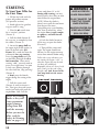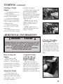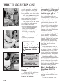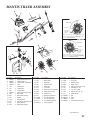
1
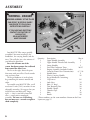
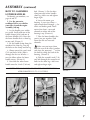
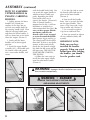
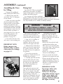
Tiller/Cultivator
OWNER’S MANUAL
WELCOME TO THE WORLD
OF MANTIS GARDENING!
Here’s your new MANTIS Tiller . . .
the lightweight wonder that’s
“Changing the Way People Garden.”
Unlike big tillers, your MANTIS Tiller
weighs only 9 kg (20 pounds). So it
lifts easily, handles smoothly, tills and
weeds precisely. And, unlike other
small tillers, it features serpentine tines
that churn soil to 25 cm deep (10
inches). It creates a soft, smooth seed
bed, even in problem soil.
Once you know how to use your tiller
correctly, we guarantee you’ll love it.
So first, please read this manual. It
shows, step by step, how to use your
tiller safely. Plus, it shows how the
MANTIS Border Edger can make light
work of your edging needs.
If you have questions about any topic
in this Manual, or for the name of
your local dealer, call 1-800-363-7333
toll free, Monday - Friday, 8:00 a.m.
to 5:00 p.m., Atlantic Time, or ask for
Customer Service.
If you wish to order Mantis
Attachments, call 1-800-363-7333 toll
free and ask for our sales department.
TABLE OF CONTENTS
Safety Rules & Warnings . . . . . . . . . . . . . . . . .3-5
Safety Decals . . . . . . . . . . . . . . . . . . . . . . . . . . .4
Engine & Fuel Warnings . . . . . . . . . . . . . . . . . .5
Assembly and Mixing Fuel . . . . . . . . . . . . . . .6-9
Starting . . . . . . . . . . . . . . . . . . . . . . . . . . . .10-11
Additional Information . . . . . . . . . . . . . . . . . .11
What to Do Just In Case . . . . . . . . . . . . . . .12-13
Getting to Your Garden . . . . . . . . . . . . . . . . . .13
Tilling & Cultivating . . . . . . . . . . . . . . . . .14-16
Tine Positioning . . . . . . . . . . . . . . . . . . . . .16-17
Cultivating . . . . . . . . . . . . . . . . . . . . . . . . . . . .16
2
Maintenance . . . . . . . . . . . . . . . . . . . . . . . .17-20
Storage . . . . . . . . . . . . . . . . . . . . . . . . . . . .21-22
Trouble Shooting & Specifications . . . . . . .23-24
Service Maintenance Guide . . . . . . . . . . . . . . .25
Using the Border/Edger Attachment . . . . . . . .26
MANTIS Tiller Assembly Layout . . . . . . . . . . .27
Engine Parts Assemblies . . . . . . . . . . . . . . .28-29
Notes . . . . . . . . . . . . . . . . . . . . . . . . . . . . . . . .30
The MANTIS Promise . . . . . . . . . . . . . . . . . . .31
Limited Warranty Information . . . . . . . . . . . .32
SAFETY RULES & WARNINGS
You will notice throughout this Owners Manual Safety Rules and Important Notes. Make sure you
understand and obey these warnings for your own protection.
I. Special Safety Information
! WARNING • DANGER
!
ATTENTION: THIS SYMBOL POINTS OUT
OUR IMPORTANT SAFETY INSTRUCTIONS.
WHEN YOU SEE THIS SYMBOL, !
HEED IT’S WARNING!! STAY ALERT!!
! WARNING • DANGER
!
TO REDUCE THE POTENTIAL FOR ACCIDENTS, COMPLY WITH
THE SAFETY INSTRUCTIONS IN THIS MANUAL.
FAILURE TO COMPLY MAY RESULT IN SERIOUS PERSONAL
INJURY, AND/OR EQUIPMENT AND PROPERTY DAMAGE.
II. Safety & Warnings
! WARNING • DANGER
!
IMPROPER USE OR CARE OF THIS TILLER
OR FAILURE TO WEAR PROPER PROTECTION
CAN RESULT IN SERIOUS INJURY.
READ AND UNDERSTAND THE RULES FOR SAFE OPERATION
AND ALL INSTRUCTIONS IN THIS MANUAL.
WEAR HEARING AND EYE PROTECTION.
! WARNING: The Engine Exhaust from this product contains chemicals known
to the State of California to cause cancer, birth defects or other reproductive harm.
PRODUCT EMISSION
. DURABILITY
The 300 hour emission durability compliance period is the time span selected by the manufacturer certifying the
engine emissions output meets applicable emissions regulations, provided that approved maintenance procedures are
followed as listed in the Maintenance Section of this manual
3
III. Safety Decal Information
An important part of the safety system incorporated in this tiller are
the warning and information decals found on various parts of the tiller.
These decals must be replaced in time due to abrasion, etc. It is your responsibility
to replace these decals when they become hard to read. The location and part
numbers (P/N) of these decals are illustrated on Page 27.
P/N 400620
CUTTING HAZARD; KEEP
FEET AND HANDS AWAY
FROM ROTATING TINES.
DO NOT CARRY THE
TILLER IN THIS
POSITION.
READ OWNER’S MANUAL
BEFORE USING TILLER, OR
PERFORMING ANY REPAIR
OR MAINTENANCE. KEEP
OWNERS MANUAL IN A
SAFE PLACE.
CAUTION: WHEN ASSEMBLING
THE HANDLES, MAKE SURE
FUEL TANK FACES OPERATOR.
THIS IS THE REAR OF THE
TILLER, REFER TO ASSEMBLY
INSTRUCTION ON PAGE 7.
INCORRECT ASSEMBLY.
DON’T FUEL, REFUEL,
OR CHECK FUEL WHILE
SMOKING, OR NEAR AN
OPEN FLAME OR
OTHER IGNITION
SOURCE.
P/N 4043
IMPORTANT ENGINE INFORMATION
ENGINE FAMILY : 4EHXS.0214KI DISPLACEMENT : 21.2cc
EMISSION COMPLIANCE PERIOD: 300 HOURS
THIS ENGINE MEETS U.S. EPA PH2 AND 2005 2006 CALIFORNIA EMISSION REGULATIONS
FOR SOREs. REFER TO OWNER'S MANUAL
FOR MAINTENANCE SPECIFICATIONS AND
ADJUSTMENTS.
EMISSION CONTROL -The emission control
system for this
engine is EM
(Engine Modification).
Emission Control Label
located on Engine.
EXAMPLE ONLY,
information on label
varies by FAMILY).
! WARNING
•
WEAR EAR AND EYE
PROTECTION.
MIX UNLEADED GAS
WITH 2 CYCLE 50:1
OIL.
DANGER !
IF THE TILLER IS USED IMPROPERLY OR SAFETY PRECAUTIONS ARE NOT FOLLOWED,
THE USERS RISK SERIOUS INJURY TO THEMSELVES AND OTHERS.
READ AND UNDERSTAND THIS MANUAL BEFORE ATTEMPTING TO OPERATE THIS TILLER.
IV. Warnings - Do’s
Read and understand the
owner’s manual. Pay
particular attention to all
sections regarding safety.
1. Always keep a firm grip on
both handles while the tines are
moving and/or the engine is running.
BE AWARE!! The tines may coast
after throttle trigger is released. Make
sure tines have come to a complete
stop and engine is off before letting
go of the tiller.
2. Always maintain a firm footing
and good balance. Do not overreach
while operating the tiller. Before you
start to use the tiller check the work
area for obstacles that might cause
you to lose your footing, balance or
control of the machine.
3. Thoroughly inspect the area
where equipment is to be used and
remove all objects, which can be
thrown by the machine.
4. Always keep area clear of
children, pets, and bystanders.
5. Always stay alert. Watch what
you are doing and use common
4
sense. Do not operate unit when
fatigued.
6. Always dress properly. Do not
wear loose clothing or jewelry, they
might get caught in moving parts.
Use sturdy gloves. Gloves reduce the
transmission of vibration to your
hands. Prolonged exposure to
vibration can cause numbness and
other ailments.
7. While working, always wear
substantial footwear and long
trousers. Do not operate the
equipment when barefoot or wearing
open sandals.
8. Always wear ear and eye
protection. Eye protection must meet
ANSI Z 87.1. To avoid hearing
damage, we recommend hearing
protection be worn whenever using
the equipment.
9. To reduce fire hazard, keep the
engine, and petrol/gas storage area
free of vegetative material and
excessive grease.
10. Start the engine carefully,
according to the manufacturer’s
instructions and with feet well away
from tool(s).
11. Keep all nuts, bolts and screws
tight to be sure the equipment is in
safe working condition.
12. Use extreme caution when
reversing or pulling the machine
towards you.
13. Work only in daylight or good
artificial light.
14. Always be sure of your footing
on slopes.
15. Exercise extreme caution
when changing direction on slopes.
16. Always keep a safe distance
between two or more people when
working together.
17. Always inspect your unit
before each use and ensure that all
handles, guards and fasteners are
secure, operating, and in place.
18. Always maintain and examine
your Tiller with care. Follow
maintenance instructions given in
manual.
19. Always store tiller in a
sheltered area (a dry place), not
accessible to children. The tiller as
well as fuel should not be stored in a
house.
V. Warnings - Don'ts
Don’t use tiller with one hand.
Keep both hands on handles with
fingers and thumbs encircling
the handles, while tines are
moving, and engine is running.
Don’t overreach. Keep a good
footing at all times.
Don’t run with the machine,
walk.
Don’t work on excessively
steep slopes.
Don’t attempt to clear tines
while they are moving. Never try
to remove jammed material
before switching the engine off
and making sure the tines have
stopped completely.
Don’t allow children or
incapable people to operate this
tiller.
! WARNING
•
Don’t operate while under
the influence of alcohol or drugs.
Don’t attempt to repair this
tiller. Have repairs made by a
qualified dealer or repairman.
See that only original Mantis
parts are used.
DANGER !
HANDLE FUEL WITH CARE, IT IS HIGHLY FLAMMABLE. FUELING A HOT ENGINE OR NEAR AN IGNITION
SOURCE CAN CAUSE A FIRE AND RESULT IN SERIOUS PERSONAL INJURY AND/OR PROPERTY DAMAGE.
VI. Engine/Fuel Warnings - Do’s
Always use fresh gasoline in the
fuel mixture. Stale gasoline can
cause damage.
Always store fuel in containers
specifically designed for this
purpose.
Always pull starter cord slowly
until resistance is felt. Then pull
cord rapidly to avoid kickback and
prevent arm or hand injury.
laws apply on federal lands.
Always operate engine with
spark arrestor installed and
operating properly. The use of spark
arrestor mufflers is required by law
in the state of California (Section
4442 of the California Public
Resources Code), as well as in other
states or municipalities. Federal
Stop the engine whenever you
leave the machine.
Allow the engine to cool before
storing in any enclosure.
If the fuel tank needs to be
drained, this should be done
outdoors.
VII. Engine/Fuel Warnings - Don’ts
Don’t fuel, refuel or check fuel
while smoking, or near an open
flame or other ignition source.
Stop engine and be sure it is cool
before refueling.
Don’t leave the engine running
while the tiller is unattended. Stop
engine before putting the tiller
down or while transporting from
one place to another.
Don’t refuel, start or run this
tiller indoors or in an improperly
ventilated area.
Don’t run engine when
electrical system causes spark
outside the cylinder. During
periodical checks of the spark
plug, keep plug a safe distance
from cylinder to avoid burning of
evaporated fuel from cylinder.
Don’t check for spark with
spark plug or plug wire removed.
Use an approved tester.
Don’t crank engine with spark
plug removed unless spark plug
wire is disconnected. Sparks can
ignite fumes.
Don’t run engine when the
odor of gasoline is present or
other explosive conditions exist.
Don’t operate the unit if
gasoline is spilled. Clean up spill
completely before starting engine.
Don’t operate your tiller if
there is an accumulation of debris
around the muffler, and cooling
fins.
Don’t touch hot mufflers,
cylinders or cooling fins as
contact may cause serious burns.
Don’t change the engine
governor setting or over speed
the engine.
The spark ignition system meets all requirements of the
Canadian Interference-Causing Equipment Regulations.
5
ASSEMBLY
!
!
WARNING • DANGER
8,7,42
26 27
IMPROPER ASSEMBLY OF THIS TILLER
CAN RESULT IN SERIOUS INJURY.
MAKE SURE TO FOLLOW ALL
INSTRUCTIONS CAREFULLY.
IF YOU HAVE ANY QUESTIONS
CONTACT OUR FACTORY AT
1-800-363-7333
OR AN AUTHORIZED
MANTIS DEALER
1
2
5
3
39
29
Your MANTIS Tiller comes partially
assembled. You must install only the
handlebars, the carrying handle, and the
tines. This will take just a few minutes if
you follow the directions.
First, take all items out of the
carton. But do not remove the cardboard
from around the tiller’s base.
The list at the right, shows the parts
that come with your tiller. Check to make
sure you have them.
The bag of hardware is in the plastic
bag containing the owner’s manual and
video.
To assemble your MANTIS Tiller, you’ll
need two 11 mm (7/16”) wrenches or two
adjustable wrenches. We suggest that you
install all nuts and bolts only “finger
tight” — that is, one-half to one full
turn — until you’ve completed
assembly. The nuts are self locking,
but you must use a wrench to tighten
them completely.
6
40
Quantity
1
1
2
1
1
Description
*Key #
Upper Handle Assembly
2
Upper Handle Throttle Side Assembly
1
Lower Handles
3
Pair Tiller/Cultivator Tines
26/27
Engine Assembly (includes Fender
Guard & Worm Gear Transmission)
8, 7, 10
1
Handle Brace
5
1
Plastic Carrying Handle
29
1
Bag of Hardware Containing:
2
Cap Screws
34*
4
Lock Nuts
35
2
Bolts (3” long)
36
2
Tine Retaining Pins
28
2
Handle Clamps
38
1
Throttle Clips
6
2
Bolts
39
2
Knobs
40
*These numbers are the same numbers shown on the Parts
Layout on page 27.
ASSEMBLY (continued)
HOW TO ASSEMBLE
LOWER HANDLES
To identify part numbers, see
pages 6 and 27.
1. Use the protective
cardboard sleeve to stabilize
your tiller. Stand the engine
assembly (#8) up.
2. Lay the handle parts within
easy reach. You’ll need one of the
handle clamps (#38) and one of
the lower handles (#3). Note that
the lower handles have a short leg
on one end. (Picture 1)
3. Fit the handle clamp along the
outside of the short leg. Line up
the holes on the clamp and the leg.
4. Choose one of the two 3-inch
(7.62 cm) bolts (#36). Slide it
through the first set of holes —
near the elbow where the lower
handle curves. (Picture 2)
5. Now slide the other lower
handle onto the 3-inch (7.62 cm)
bolt. (Picture 3.) Fit the other
clamp onto this other handle’s
short leg. Add a nut and tighten
finger tight.
6. Locate the worm gear
housing. It starts just above —
and extends down through — the
tiller’s red fender guard. You’ll
notice that there’s a recessed
channel on either side of the
housing’s top. (Picture 4.)
7. Take the lower handles that
you’ve just put together. Slide
them into the two recessed
channels.
!
Make sure you insert them
from the rear of the tiller (gasoline
tank faces the operator) . . . so that
the bolt fits along the back of the
housing. (Picture 5)
8. Slide the second 3-inch (7.62
cm) bolt through the second set of
holes in the short legs. Add a nut
and tighten finger tight.
NOTE: THE LOCK NUTS ARE STAMPED. FINGER TIGHT IS
APPROXIMATELY 1/2 TO 1-1/2 TURNS.
Picture 3
Picture 1
Picture 4
Picture 2
Picture 5
7
ASSEMBLY (continued)
HOW TO ASSEMBLE
UPPER HANDLES &
PLASTIC CARRYING
HANDLE.
1. Lightly squeeze the lower
handles (#3) toward one
another so that they line up
with the two smaller holes on
the carrying handle (#29). Then
slide the carrying handle over
and down the lower handles. It
will rest about four to six inches
above the engine. (Picture 1)
2. Gently pull the lower
handles out to their original
position.
3. Attach the upper handle
assembly (#1) – the handle with
the throttle cable and ground
wire – onto either handle, and
secure
with the handle knob (#40). You
can attach this upper handle to
whichever lower handle you
prefer, depending on which
hand you’d rather use to
squeeze the throttle. (Picture #2)
Note: If throttle handle is
mounted on the left, it will not
fold down as completely as
when mounted on the right.) Be
sure you have proper throttle
movements and that the
throttle cable is not wrapped
or twisted around the handle
bar. Squeeze trigger and let go.
The triangle must click in both
directions. If there is any doubt,
remove air filter and visually
check that the throttle triangle
hits both the idle screw and the
full open stop. THIS MUST BE
DONE BEFORE STARTING
THE ENGINE.
4. Follow the same steps to
install the other upper handle
onto the other lower handle.
(Picture 3)
5. Use the clip (#6) to secure
the throttle cable and wire in
place on the lower handle.
(Picture 4)
6. Now install the Handle
Brace. Line it up with the holes
on the upper handles. Then
insert a Cap Screw and a Lock
Nut on either side (Picture 5)
7. Use a wrench to tighten
Cap Screws and Lock Nuts.
8. Now use wrench to tighten
all nuts and bolts firmly and
securely.
IMPORTANT NOTE:
Make sure you have
installed the handles
properly. When you stand
behind your tiller, holding
the handles, you should
face the gasoline tank.
! WARNING: Improper throttle installation can cause
tines to rotate unexpectedly .
! WARNING • DANGER !
REMOVE TINES BEFORE STARTING ENGINE
AND MAKING ADJUSTMENTS.
Picture 1
Picture 2
8
Picture 3
Picture 4
Picture 5
ASSEMBLY (continued)
Assembling the Tines
for Tilling
1. Remove the cardboard
from around your Tiller’s base.
2. Slide the tines onto the
axle shafts. The “D” hole goes
on the outside.
3. Make sure you’ve installed
the tines properly for tilling.
Liken the tines to your fingers.
When your palm faces the
ground, your fingers curl down.
Stand behind the tiller and hold
your hand next to the tines. Do
the tine blades curl down, as
your fingers do? If so, they are
in the tilling position. (To
switch to the cultivating
position, see page 15.)
4. To secure each tine to the
axle, insert a tine retaining pin.
IMPORTANT NOTE:
Before you use your
MANTIS Tiller, read the
safety rules & warnings
on pages 3-5.
Mixing Fuel
Your MANTIS Tiller is powered by a
commercial two stroke, air cooled
engine which requires a fuel mixture of
gasoline and lubricating oil.
Use a mixture of 50 parts unleaded
regular gasoline and 1 part two-stroke MANTIS oil (50:1.) Use
branded 89 octane (R+M+2) unleaded gasoline or ethanol (maximum
10% ethyl alcohol, or 15% MTBE, no methyl alcohol.)
!
WARNING • DANGER
!
FUEL IS EXTREMELY FLAMMABLE. HANDLE IT WITH
CARE. KEEP AWAY FROM IGNITION SOURCES. DO NOT
SMOKE WHILE FUELING YOUR EQUIPMENT.
Your Mantis Tiller comes with
a free pre-measured bottle of
two-cycle engine oil. Here’s how
to mix the oil with the gasoline:
1. Pour 2.5 l (2/3 gallon) of
the gasoline into a safe
container. Do not mix the fuel
and oil in the engine fuel tank.
2. Add one bottle (100 ml/3.44
ounces) of two-cycle engine oil to
the gasoline and mix. Then add
the other 2.5 litres (2/3 gallon) of
the gasoline.
3. Screw the cap onto the
gasoline can. Then swirl the can
to blend the oil and gas.
4. Carefully pour the fuel mix
into the tiller’s fuel tank. After
putting the fuel tank’s cap back
on, wipe up any spilled fuel
from tank and gasoline can.
IMPORTANT:
Two stroke fuel separates and
ages. Do not mix more than you
will use in a month. Using old
fuel can cause difficult starting or
engine damage. Shake fuel
container to thoroughly mix fuel
before each use. Do not attempt
to run your engine on gasoline
only, use proper fuel mixture.
Need more pre-measured
engine oil? You can order it
directly from Mantis. Just call
toll free 1-800-363-7333 and ask
for our Sales Dept.
Remember …
•Always mix two-cycle oil with
gasoline before fueling your
tiller. Never, ever run your tiller
on gasoline alone. This will ruin
your engine and void all
warranties.
•Always use a clean gas can and
always use unleaded gas.
•Never try to mix the oil and
gasoline in the engine fuel tank.
•Always mix oil and gas in the
proper proportions: 5 litres (1.3
gallons) of unleaded gasoline to
100 ml (3.44 ounces) of twocycle engine oil.
IMPORTANT NOTE:
Do not use old or stale
oil/gasoline mixture.
Always use the proper
oil/gasoline mixture. If you
do not, your engine will
suffer rapid, permanent
damage. And you will void
the engine warranty.
9
STARTING
! WARNING !
To Start Your Tiller for
the First Time:
1. Fill the fuel tank with the
proper oil/gasoline mixture.
(See previous section.)
2. Hand tighten the gasoline
cap just until it’s snug.
3. Place the o/I switch into
the I “start/on” position.
(Picture 1)
4. Pull the choke button all
the way out, to completely close
the choke. (Picture 2)
5. Locate the purge bulb on
the upper right of the engine, in
front of the fuel tank. (See
Picture 3) It sends fuel into the
carburetor, for easy starting.
Press the purge bulb until you
see fuel flow through the clear
fuel return line. Since you’re
starting “cold,” you may need to
press six to eight times. As soon
as fuel starts flowing through
the clear fuel line, stop pressing!
(Picture 3)
6. Don’t press the throttle
trigger during the starting of the
engine.
7. Pull the starter cord
(Picture 4) until resistance is
felt. Then give the recoil starter
cord a few brisk pulls until the
engine fires. Note: Pull the
starter cord about 12" to 18".
During cold starting, you may
need to pull at least three or four
times before the engine fires.
NOTE: When the choke is
closed, never pull the cord more
than four or five times.
Overpulling may cause flooding.
Also, bear in mind that, when
the engine fires, it only coughs
or sputters, and will not run
on choke.
8. Push the choke button in,
all the way, to open the choke.
(Picture 5)
9. Then pull the starter cord
again. The engine should start
and run. Let the engine warm up
two to three minutes before using.
Follow these steps whenever you
are starting the engine “cold”, or
when the engine has run dry and
you have just added fuel.
Remember, always use short, brisk
pulls. Don’t give the cord a long,
forceful yank. And, do not let the
cord snap back into the starter
housing.
DO NOT SQUEEZE THE
THROTTLE TRIGGER
WHEN STARTING.
MAINTAIN PROPER IDLE
SPEED ADJUSTMENT
(2500-3100 RPM)
Picture 4
Picture 5
Never use starting
fluids as they will
cause permanent
engine damage.
Using them will
void the warranty.
Before you use the
tiller, read the
Safety & Warning
rules on pages 3-5.
Picture 1
10
AVOID ACCIDENTAL
BLADE ENGAGEMENT
Picture 2
Picture 3
STARTING (continued)
Starting a Warm
Engine
1. Push ignition switch to I
“start/on” position.
2. Push choke button in to
the RUN (open) position.
3. If there is no fuel in the
clear return line, push primer
bulb 3-4 times or until fuel is
visible in the line.
4. Pull starter rope using
short pulls, 1/2 to 2/3 of the
rope length.
5. If engine fails to start in 4
pulls, use “First Time” starting
procedure on page 10.
6. With engine running, and
both hands on the handles,
press the throttle lock out
button (Picture 1), then squeeze
the throttle trigger gradually to
increase the engine speed and
engage the tines.
NOTE: Once the throttle
trigger is squeezed, you can
release the lockout button
(Picture 2).
NOTE: Step #6 must be
repeated each time your tiller
trigger is released.
ADDITIONAL INFORMATION
! WARNING • DANGER
!
IF ENGINE DOES NOT STOP WHEN SWITCH IS PUT IN THE STOP
POSITION, RELEASE THE THROTTLE, ALLOW ENGINE TO IDLE.
PUT THE TILLER DOWN, AND PULL THE CHOKE BUTTON OUT
TO COLD START (CLOSED) POSITION.
CHECK AND RETURN IGNITION SWITCH TO ON POSITION
BEFORE STARTING ENGINE AGAIN.
How to Stop the
Engine
Simply push the o/I
“stop/start” switch to “o”
(Picture 3). This will stop the
engine instantly. If it should
ever fail to do so, just pull out
the choke button. The engine
will stop at once.
About the Choke
The choke controls the
amount of air drawn into the
engine. Your tiller will run only
if the choke is open — that is, if
the choke is pushed in.
Picture 1
Picture 2
A Tip for Extending
Your Engine’s Life
After you start the engine, let
your tiller warm up for two to
three minutes before you use it.
Then, before you put your tiller
away, let it idle for a minute to
give the engine a chance to cool
down.
A Special Feature
(with the idle set
properly and the
engine running)
Even when the engine is
running, the tines won’t turn
unless you press the throttle
lock out button and squeeze the
throttle lever on the handlebars.
And, when you release the
throttle lever, the tines will stop.
Picture 3
11
WHAT TO DO JUST IN CASE
Picture 1
Picture 2
If you follow the normal
starting procedure, you should
have no problem starting your
tiller. But, just in case you do
have problems, here’s what to do.
Make sure the o/I switch is on
I “start.” You’d be surprised how
many people forget to push the
switch into the “I” position.
If the switch was on “o” when
you pulled the cord, you may
have flooded the engine.
•First, examine the spark plug.
Use the special wrench that
comes with our optional
MANTIS Handy Item Kit (Item
MT1422) or a spark plug
wrench. (Picture 1)
•Remove the cap over the spark
plug.
•Unscrew the spark plug.
(Picture 2)
IMPORTANT NOTE:
To avoid possible damage
to the threads, do not try
to remove the plug from a
hot aluminum cylinder
head.
! WARNING !
MAKE SURE THE START/STOP
SWITCH IS IN THE STOP
POSITION.
KEEP PLUG WIRE AWAY FROM
ENGINE TO AVOID
UNINTENTIONAL SPARK.
Picture 3
Starting a Flooded
Engine
1. If the end of the spark plug
is wet, the engine may be
flooded. Make sure the switch
is in the “o” position,
12
disconnect spark plug wire and
remove plug. Use a paper towel
or a clean rag to dry the spark
plug, then, with the spark plug
out of the engine, pull the
starter cord several times.
Next, replace the spark plug.
Use the wrench to tighten it and
replace the cap. Next, put the
switch in the “I” position and
pull the choke button out. Pull
the starter cord three or four
times until the engine coughs or
sputters. Open the choke (push
the choke button in) and pull
the cord a few times. The engine
should start and run.
2. If the end of the spark plug
is dry, check to see if the fuel
line is blocked. First loosen the
fuel cap to relieve the pressure in
the tank. The fuel line runs from
the fuel tank to the carburetor.
Pull it off at the carburetor end.
Fuel should drip slowly from the
line. Wipe off any excess or
spilled fuel.
If fuel does not drip from the
line, check the line for any bends
or pinches. (Picture 3). Kinks in
the line restrict the flow of fuel
to the engine. Just straighten out
the line. Reconnect. Then follow
the normal starting procedure.
If fuel drips too freely, the line
may be disconnected from the fuel
filter. You’ll find the fuel filter
inside the fuel tank. Just re-attach
the line to the filter, and put the
filter back in the tank. Then follow
the normal starting procedure.
Here’s Another Way to
Start Your MANTIS
Tiller
If you follow the steps above
and your engine still won’t start,
try this:
1. Push the switch to “start.”
WHAT TO DO JUST IN CASE (continued)
2. Push in the choke button
to open the choke.
3. Press the plastic bubble a
few times.
4. Give the starter cord a few
short, quick pulls. The engine
should start and run.
5. If the engine does not start,
then pull out the choke button
to close the choke. Pull the
starter cord four to five times.
The engine should sputter or
cough.
6. After the engine sputters,
push the choke button in. Then
pull the starter cord. The engine
should start and run.
7. If the engine still does not
start, repeat steps 2 through 6.
8. If the engine still does
not start, call 1-800-363-7333
and ask for Customer Service
or the name of your local
MANTIS dealer.
IMPORTANT NOTE:
Never use starting fluids.
Starting fluids will cause
permanent engine
damage. Using them will
void the warranty.
IMPORTANT NOTE:
Before you use your
MANTIS Tiller, read the
safety rules & warnings
on pages 3-5.
GETTING YOUR TILLER TO YOUR GARDEN
Walk it.
Once your tiller is running,
you can “walk” it to your
garden. Just press the throttle
lock out button and squeeze the
throttle lever gently and let the
tiller “tip-toe” across your yard
on its tines. It won’t hurt your
lawn or driveway.
Carry It.
Make sure the engine is off.
Then use one hand to grasp the
Picture 1
convenient carrying handle. Use
the other hand to hold the
handlebars. (Picture 1) Then lift
your tiller and carry it to your
garden. Since it weighs only 20
pounds, it won’t strain your
muscles or tire you out!
Take It for a Ride.
You can easily transport your
MANTIS Tiller to a friend’s or
relative’s house. Just empty the
fuel tank. (This is crucial.)
Then stow your Tiller in the
trunk of your car or truck. It
fits easily. And you can put it in
and take it our without
straining your back.
! WARNING !
NEVER CARRY YOUR TILLER
AS THE PERSON IN PICTURE 3
IS DOING. IF YOU DO, AND THE
TINES ENGAGE, YOU COULD
SUFFER SERIOUS INJURY.
Picture 2
13
TILLING
! WARNING • DANGER
!
THE OPERATOR OF THIS TILLER IS RESPONSIBLE FOR
ACCIDENTS OR HAZARDS OCCURRING TO HIMSELF,
OTHER PEOPLE OR THEIR PROPERTY.
Picture 1
Picture 2
Picture 3
14
Now You’re Ready to
Use Your MANTIS Tiller.
You Can Even Control
Depth.
If you’ve seen other tillers,
your MANTIS Tiller may surprise
you. It tills best when you pull it
backward! You see, when you
pull your MANTIS Tiller
backward, you give extra
resistance to the tines, so they
dig deeper.
(Picture 1)
What’s more when you go
backward, you erase your
footprints. So your soil stays light
and fluffy. With other tillers, by
contrast, you walk right over the
soil you’ve just tilled, packing it
down, so it’s less plantable.
For Deeper Tilling:
Move your Tiller slowly back
and forth, as you would a
vacuum cleaner. Work the same
area over and over until you’ve
dug to your desired depth.
(Picture 3)
Run Your MANTIS
Tiller like a Vacuum
Cleaner.
Place your Tiller at the head of
the row or area you want to till.
Start it up. Then use an easy
rocking motion. First, pull your
Tiller backward. Then use an
easy rocking motion. Again, pull
your Tiller backward. Then, let it
move forward just a little bit.
Then pull it backward again.
This will help you till deeper.
Keep repeating these steps
until you’ve tilled an entire row.
Start again on the next row. It’s
much like running a vacuum
cleaner! (Picture 2)
For Shallow Tilling:
Switch the tines to the
cultivating position. (See page
15 to learn how.) Then move
your Tiller quickly over your
soil surface.
For Big Weeds or Tough Roots:
Let your Tiller rock back and
forth over the tough spot, until
the tines slice through the weed
or root.
Your MANTIS Tiller
Handles Special Tilling
Projects.
Want to turn part of your lawn
into a colorful flower border?
Your MANTIS Tiller makes it
easy! Just run your Tiller back
and forth until the sod begins to
break up. Then continue tilling.
Your Tiller will chop the clumps
of sod until they’re fine. Then, it
will work them into the soil.
Pretty soon, you’ll have a soft,
fresh planting bed.
TILLING/CULTIVATING
! WARNING • DANGER
!
IF YOUR TINES GET JAMMED OR ENTANGLED, SHUT OFF THE ENGINE AT ONCE.
REMOVE THE SPARK PLUG WIRE THEN REMOVE THE OBSTRUCTION
WHILE THE ENGINE IS OFF. NEVER TRY TO REMOVE AN OBSTRUCTION
WHILE THE ENGINE IS RUNNING. SERIOUS INJURY CAN RESULT.
How about a family-size
vegetable garden?
Nowadays many gardeners
prefer small gardens —
especially in the suburbs, where
space is at a premium. But, if
you’re fortunate enough to own
a large lot, you can create a
bigger garden — a half acre or
more. Here’s how:
1. First, hire someone with a
tractor or big tiller to break
ground for you. This is a onetime-only investment that’s well
worth the small cost.
2. Then, use your Tiller to
break up any remaining clumps
of soil or sod. Unlike a tractor
or big tiller, your MANTIS Tiller
is a precision tool. It will
pulverize your soil into a
smooth seed bed.
Picture 1
Picture 2
Your MANTIS Tiller
Makes Weeding a
Pleasure!
How to Switch From
Tilling to Cultivating
Position
As a tiller, your MANTIS
Tiller works the soil down to
10” (25.4 cm) deep. But, as a
cultivator, it gently cultivates
the surface, only 2” to 3” (5.09
cm to 7.62 cm) deep.
First, you must change the
tines to the weeding position.
This takes less than a minute.
Then, your MANTIS Tiller’s
sharp “tine teeth” will slice up
those pesky weeds, burying
them as you go along. And,
since the tines in this position
won’t dig too deep, they won’t
hurt your plants’ precious root
systems.
The result? Your Tiller will
cut your weeding time in half,
and turn a tiresome chore into a
pleasure.
1. Make sure your Tiller is
off.
2. Remove the retaining pins
from the tines.
3. Remove the tines from the
axle.
4. Place the right-side tine
onto the left-side axle. Place the
left side tine onto the right-side
axle. The “D” hole should be to
the outside.
5. Here is how to make sure
you’ve installed the tines
properly. Stand behind the Tiller
and hold your hand, palm up,
next to the tines. Do the tine
points curl up, as your fingers
do? If so, they are in the correct
cultivating position.
6. Reinsert the pins.
15
CULTIVATING
Now You’re Ready to
Cultivate or Weed.
Tilling Position
Tine teeth point in the same
direction as the rotation of the
tine; or toward the front of the
Tiller, away from the operator.
Guide your Tiller where you
want to weed and start it up.
Pull your Tiller backward
slowly, then let it move forward
a bit, in a gentle rocking
motion. Watch it slice, shred,
and bury those weeds!
Got tough weeds? Lighten
your pressure on the throttle to
slow your Tiller down. Then
work back and forth until your
Tiller chops up the weeds. It’s
easy and effective!
Remember, any tiller will
tangle in tall grass, stringy
vines, or super-big weeds. So, if
you have a “backyard jungle,”
first use a knife, pruner, or
brush cutter to chop up the
overgrowth. If the tines become
tangled anyway, push the
switch to the “o” position to
turn the engine off completely
before trying to clear them.
The optional tine Detangler
(Item #1322) will clear tines in
a jiffy. Call 1-800-363-7333 for
details. (Ask for the Sales
Department.)
Your Mantis Tiller Will
Weed Between Narrow
Rows!
Your Mantis Tiller is a
precision weeder that easily fits
in tight places. So don’t be afraid
to weed anywhere: between
plants and shrubs; in corners;
against fences; on raised beds; in
wide rows; even in very narrow
rows. Your Mantis Tiller weeds
six* to nine inches wide. So you
can run it in a tightly planted
garden without damaging your
delicate plants. That’s good news
for suburban gardeners, who
often have to plant rows close
together!
*With optional Planter
Furrower attachment
(Item MT6222).
Cultivating Position
Tine teeth point in the
opposite direction as the
rotation of the tine. Tines point
toward the back of the tiller, or
toward the operator.
16
MAINTENANCE
Check the Air Filter Often
A wet or dirty air filter can
affect the way your engine starts,
performs, and wears. So, it’s a
good idea to check your air filter
once a month.
If you work in dusty soil, or if
you want to be on the safe side
— then check your filter more
often (for instance, before each
use). But be sure to replace it at
least once a year, in the spring or
fall. Clean or change it as
needed. It is recommended to
change the air filter yearly.
4. If the air filter needs
cleaning or no longer fits
properly, remove it. Just lift an
edge carefully and “peel” it out.
(Picture 3)
5. Use a brush to remove
debris from the pad.
6. If the air filter is so dirty
that it won’t come clean, you
must replace it or severe engine
damage will occur. Order a new
one directly from our Customer
Service Dept. Call 1-800-3637333.
7. Insert your clean filter
inside the air-cleaner cover.
IMPORTANT! Make sure
filter is “seated” properly
in the cover. The filter
must fit snugly inside the
rim that holds the filter in
place.
Installing the filter incorrectly
will cause engine damage and
void the warranty. Fit the cover
back over the air cleaner. (Again,
make sure to clear the choke
button.)
8. Tighten the wing nut to
secure the cover.
How to Check, Clean and
Change the Air Filter
1. Loosen the wing nut on the
side of the air-cleaner cover. (See
Picture 1, or look up Key #1 in
Air Cleaner Parts Assembly on
page 28.)
2. Take off the cover. Make
sure to clear the choke button.
(Picture 2)
3. The air filter is the white
pad on the inside of the aircleaner cover. Check whether it
is soiled or moist.
Picture 1
Picture 2
Note:
Please check the lip
on the Air Cleaner
Cover. If the lip is
chipped or cracked,
it should be
replaced. This will
prevent dirt from
being ingested
through the
carburetor into the
inside of the engine.
Picture 3
17
MAINTENANCE (continued)
How to Check the Grease
Level Inside the
Worm Gear Housing
When we built your MANTIS Tiller,
we lubricated the worm gear housing
thoroughly.
It is imperative that you inspect the
grease level once a year. Simply
remove the cover plate on the worm
gear housing. (Picture 1) Then check
to make sure the grease comes almost
to the top of the housing. If it doesn’t,
add lithium #0 grease (Item M9985.)
This is the only way to add grease to
the worm gear housing. (Picture 2) To
purchase Mantis grease, call our sales
Dept. - 1-800-363-7333.
Please do not overfill. Too much
grease can create pressure, which
could cause seals to fail or the clutch
to slip.
Picture 1
Picture 2
Clear Blockages From the
Fuel Line & Filter:
After you’ve used your Tiller for a
few seasons, check for blockages in
the fuel tank and fuel filter. Such
blockages can keep your Tiller from
starting.
Clear any blockages you see in the
tank, fuel filter, or fuel line.
Remember: The fuel filter is located
inside the tank. (See Picture 3) Then
use the normal starting procedure to
start your Tiller.
18
Picture 3
MAINTENANCE (continued)
! WARNING•DANGER !
REMOVE TINES BEFORE
STARTING ENGINE AND
MAKING ADJUSTMENTS
What to Do if Your
Engine Idles Too High
What if your engine runs too
fast … or if the tines turn the
instant you start the Tiller? You
may need to adjust the idle
screw (Key #19 under
Carburetor on page 28) by itself
right below the H and L screws.
Gently turn it counterclockwise. You’ll know you’ve
adjusted it correctly when the
axles do not turn at low idle.
What to Do if Your
Engine Runs “Rough”
If your engine runs “rough”
or stalls, you may need to adjust
the carburetor and idle screws.
If you remove the air-cleaner
cover, you’ll see the two
carburetor, adjustment screws
next to the choke button.
(Picture 1)
The “RED” screw is the
HIGH-speed adjustment…The
“WHITE” screw is the low
speed adjustment.
First, remove the tines from
the axle. Then start engine. Let
it run for two to three minutes.
“FLASH” the choke several
times during the warm-up to
clear any air from the Fuel
system.
Then stop the engine after it
reaches operating temperature.
Now, turn the RED, highspeed screw counter-clockwise
all the way to stop…Then turn
the WHITE, low speed screw
halfway between the counterclockwise and clockwise stop
positions.
Now restart the engine to
finish the carburetor
adjustment.
Run the engine at full speed
two or three seconds to clear
out any excess fuel. Then return
to idle.
Now, accelerate the engine to
full throttle several times to
check for a smooth transition
from idle to high speed.
If the engine hesitates turn
the WHITE, low-speed screw
counter-clockwise one-eighth of
a turn. Then accelerate the
engine.
Repeat the adjustment until
you get a smooth transition to
high speed.
Picture 1
19
MAINTENANCE (continued)
How to Reseat the
Flange
At some point, you may find
that the tines won’t turn when
you press the throttle. This
may mean the engine isn’t
sitting all the way down on the
worm gear housing.
Perhaps you’ve been using
your Tiller for several years.
Or perhaps you’ve removed
the engine for use with our
hedge trimmer attachment,
then replaced it. In either case,
the flange bolt (Key #38, page
29) may have come loose and
lifted the engine up.
If this happened you’ll
notice a gap between the
bottom of the engine flange
(clutch case) (Key #39, page
29) and the top of the worm
gear housing. (Picture 1)
To fix this, loosen the flange
bolt. Take the engine off the
worm gear housing. Notice
the hex head on top of the
drive shaft (Key #22, Page 27).
Inside the flange housing,
you’ll find the clutch drum
(Key #31, Page 29). Make sure
the hex head lines up with the
clutch drum inside the flange
housing.
Then put the engine back
on the worm gear housing.
Make sure the plastic carrying
handle is not under the fuel
tank.
Picture 1 … Note how the
engine doesn’t sit all the way
down on the transmission.
If you’ve followed these steps
properly, there will be no gap
between the engine flange and
the worm gear housing.
(Picture 2) Make sure you
tighten the flange bolt!
Picture 2 … Note how the
engine sits all the way down on
the transmission.
Cleaning the Muffler
Screen
1. Take out the spark plug.
2. Remove the red cylinder
cover, (Key #32) which is held
on by 1 phillips-head screw,
(Key #33) and 1 hex-head
screw, (Key #34) which you
will need an allen wrench
to remove.
3. You will see the metal
exhaust guide, held on by 3
more phillips-head screws.
(Key #26) Remove the exhaust
guide.
4. Behind the exhaust guide
(Key #25) will be the muffler
gasket (Key #24) and muffler
screen (Key #23). The screen
sits under the gasket.
5. If the screen (Key #23) is
clogged with deposits, it needs
to be cleaned. Use carburetor
cleaner, and any brush that is
not metal. Brush the screen
until you are able to see
through it.
6. If the screen remains
plugged after attempts at
cleaning, it must be replaced.
26
25
24
23
19
22
21
20
18
32
! WARNING•DANGER !
DO NOT USE
GASOLINE OR OTHER
FLAMMABLE SUBSTANCE
33
20
34
STORAGE
!
!
WARNING•DANGER
DO NOT STORE IN AN AREA
WHERE FUEL FUMES MAY
ACCUMULATE AND REACH A
FLAME OR SPARK.
Each fall — or before you
store your Mantis Tiller for
any long period — be sure to
take these measures:
1. Do not store your Tiller
with fuel still in it. Even under
ideal conditions, stored fuel
containing ethanol or MTBE
can start to go stale in 30 days.
And, since stale fuel has a
high gum content, it can clog
the carburetor, this, in turn,
will restrict fuel flow. So,
when you’re ready to store
your Tiller, or will not be
using it for more than 2
weeks, drain the fuel tank
completely. (Picture 2)
2. Next, restart the engine
to make sure no fuel is left in
the carburetor. Then run the
engine until it stops. This will
prevent gum deposits, forming
inside of the carburetor and
possible engine damage.
3. Disconnect spark plug
wire and remove the spark
plug. (Use the wrench that
comes in our optional Handy
item Kit, Item MT1422. Or
use a 19mm or 3/4” sparkplug wrench.) Pour about a
teaspoon of clean, air-cooled,
two-cycle oil through the
spark-plug hole into the
combustion chamber. (Picture 3)
Leaving the spark plug out
slowly pull the starter cord two
or three times to coat the
inside of the cylinder wall.
Picture 1
4. Inspect the spark plug, and,
if necessary, clean it. If you
need to replace it, buy a
NGK-BPMR-7A. A
replacement spark plug is
included in the optional
Handy Item Kit item MT1422.
5. Install the spark plug, but
leave the spark plug wire
disconnected.
6. Clean the air filter as
described on Page 17.
7. Clean dirt, grass, and
other materials from the entire
machine.
8. Wipe the tines with oil or
spray them with WD-40, to
prevent rusting.
9. Oil the throttle cable and
all visible moving parts. (Do
not remove the engine cover.)
Picture 2
Picture 3
21
STORAGE (continued)
10. Check the grease level in the
worm gear housing, as described
on page 18.
11. Order new parts to
replace any that are badly
worn or broken. Just call
1-800-363-7333 and ask for a local
authorized Mantis dealer.
12. Store your Tiller, in an
upright position, in a clean, dry
place. You can store with the
handles in an extended position or
folded down. (Picture #1,
preceding page)
13. To fold the handles, follow
these easy steps: Loosen the
handle knobs (#53), fold the
handles forward (see picture #1,
inset, preceding page). Tighten
knob securely. Your handles are
now folded and ready to store in a
smaller area.
14. Do you have fuel left over
from last season? Dispose of it
properly. Buy fresh oil and gasoline
next season.
How to Prepare Your
MANTIS Tiller for
Restarting
Unfold the handles into an upright or extended position. Tighten
the two handle knobs (#53)
WARNING
!
Always make sure the handle
knobs are secure before
starting your Mantis Tiller.
!
In the Spring, when you take your
Tiller out of storage, remove the
spark plug. Pull the starter cord
three or four times to clean oil
from the combustion chamber.
22
(Picture 1) Wipe oil from the
spark plug. Place the spark plug
back into the cylinder. Re-connect
the spark plug wire back on the
spark plug. Then follow the steps
on pages 9 & 10 to refuel and
restart your Tiller.
Again, Check the
Carburetor.
If your Tiller won’t restart in the
Spring — or if it lacks its usual
power — the carburetor may need
attention. Follow the steps on
page 19 for adjusting the H and L
screws. (Picture 2)
Picture 1
Check the Spark Plug
Too.
If your Tiller won’t restart, or if
it lacks full power, the spark plug
may be at fault. Check to see if the
plug is fouled with oily black
deposits. Clean or replace it if it is.
(Picture 3)
Also, check whether the center
electrode is rounded at the end,
or if the ground electrode is worn.
If either is the case, you should
replace it with a NGK-BPMR-7A
spark plug. Use a 19mm or a 3/4”
spark-plug wrench to install it.
Adjust the plug gap .024 - .028 in.
(0.6 to 0.7 mm)
Picture 2
Caution: Do not over
tighten the plug. The correct
torque is 18 to 22 ft.-lbs.
(24-30 n.m)
IMPORTANT NOTE:
To avoid possible damage
to the threads, do not try to
remove the plug from a hot
aluminum cylinder head.
Picture 3
TROUBLE SHOOTING
Problem
Cause
Remedy
1. Tines don’t turn when throttle
is depressed
• Engine is not seated properly on
the gear housing.
• Re-install engine following the
instructions on page 20 (How to
re-seat the flange).
2. Engine fails to start
• o/I switch is in “o” position.
• Move switch to “I”.
•
•
•
•
•
No fuel in tank.
Fuel strainer clogged.
Fuel line clogged.
Spark plug shorted or fouled.
Spark plug is broken (cracked
porcelain or electrodes broken)
• Ignition lead wire shorted,
broken or disconnected from
spark plug.
• Ignition inoperative
•
•
•
•
•
• Water in gasoline or stale fuel
mixture.
• Too much oil in fuel mixture.
• Drain entire system and refill
with fresh fuel.
• Drain and refill with correct
mixture.
• If flooded by over choking,
proceed according to
instructions in operation
section. If under choked, move
choke lever to closed position
and crank two or three times.
• See “Carburetor Adjustment”
• Replace gaskets.
3. Engine hard to start.
• Engine under or over choked.
• Carburetor out of adjustment.
• Gasket leaks (carburetor or
cylinder base gasket).
• Weak spark at spark plug.
Fill Tank.
Replace Strainer.
Clean fuel line.
Install new spark plug.
Replace spark plug.
• Replace lead wire or attach to
spark plug.
• Contact your local authorized
dealer.
• Contact your local authorized
dealer.
4. Engine continuously floods.
• Fuel tank vent line is not in an
upright position.
• Return the fuel tank vent line
to the upright position and
place it under the cylinder
cover in the small “pocket” in
the cylinder cover
5. There is black smoke coming
from exhaust
• The muffler screen is clogged
• Clean carbon from muffler
screen (page 20)
6. Engine misses.
• Dirt in fuel line or carburetor.
• Carburetor improperly adjusted.
• Spark plug fouled, broken or
incorrect gap setting.
• Weak or intermittent spark at
spark plug.
• Remove and clean.
• See “Carburetor Adjustment”.
• Clean or replace spark plug - set
gap to .024-.028 in. (0.6-0.7 mm)
• Contact your local authorized
dealer.
23
TROUBLE SHOOTING
Problem
7. Engine lacks power.
(continued)
Cause
•
•
•
•
Air filter clogged.
Carburetor out of adjustment.
Muffler clogged.
Clogged exhaust ports.
• Spark Arrestor Clogged.
• Poor compression.
8. Engine overheats.
• Insufficient oil in fuel mixture
• Air flow obstructed
Remedy
•
•
•
•
Clean or replace air filter.
See “Carburetor Adjustment”.
Clean carbon from muffler.
Remove muffler, rotate engine
until the piston is at top of
cylinder. With a wooden
scraper or blunt tool, remove
all carbon from exhaust ports.
Be careful not to scratch or
damage piston or cylinder
walls. Blow out all loose carbon
with compressed air. Install
muffler and gasket.
• Clean Spark Arrestor
• Contact your local authorized
dealer.
• Mix fuel as described in starting
instructions.
• Clean flywheel cylinder fins
and screen.
9. Engine noisy or knocking.
• Spark plug in incorrect heat
range.
• Bearings, piston ring or cylinder
walls are worn.
• Replace with plugs specified for
engine.
• Contact your local authorized
dealer.
10. Engine stalls under load.
• Carburetor adjustment too “lean”.
• Engine overheats.
• See “Carburetor Adjustment”.
• Remove dust and dirt from
between fins.
ENGINE SPECIFICATIONS
Dry Weight
Type of Engine
Rotation
Bore
Stroke
Spark Plug
Fuel
Fuel Oil Ratio
Gasoline
Displacement
Exhaust System
Carburetor
Ignition System
Starter
Oil
Fuel Tank Capacity
24
2.8kg — 6 lbs., 3 ounces
Air Cooled, Two stroke, Single-Cylinder, Gasoline Engine
Clockwise, viewed from TOP
32.2 mm (1.268 in.)
26.0 mm (1.04 in.)
NGK BPM8Y
Premixed two stroke fuel
50:1 ratio with MANTIS oil
Unleaded (see page 9)
21.2 cc (1.294 cu. in.)
Spark arrester muffler
ZAMA diaphragm model C1U type
Flywheel magneto, capacitor discharge ignition type
Automatic rewind type
Designated, two-stroke, air-cooled engine oil
0.5 lit. (17.0 oz.)
SERVICE MAINTENANCE GUIDE
Area
Maintenance
Frequency
Air Filter
Clean
Replace
Inspect
Replace
Clean
Replace
Check / Rebuild
Replace
Inspect / Clean
Inspect / Clean
Inspect / Clean
Check Grease
Inspect / Clean / Lubricate
Inspect / Repair
Inspect / Tighten / Replace
Inspect / Replace
Inspect / Replace
Inspect / Replace
Inspect / Replace
Inspect / Replace
Replace
Check
Clean
Replace
Daily or every 4 hrs. use
Every 3 mths. or 90 hrs. use
Monthly
Fuel Filter
Spark Plug
Carburetor
Cylinder Exhaust Port
Cooling System
Muffler (Spark Arrestor)
Gear Housing
Tines
Fuel Leaks
Fasteners
Labels
Handles
Guards / Safety Devices
Fuel Line
Starter Rope
Fuel Strainer
Choke
Ignition System
Every 3 mths. or 90 hrs. use
6 months or 270 hrs. use
6 months or 300 hrs. use
Yearly or 600 hrs. use*
Every 3 mths. or 90 hrs. use
Before Use
Monthly
Yearly
After Use
Before Use
Before Use
Before Use
Before Use
Before Use
Monthly
Monthly
Every 3 mths. or 100 hrs. use
With each re-fueling
No maintenance
For coil and flywheel
* Replacement will be required for commercial use after 600 hours. For Consumer use, cleaning every 6 months is required. Cleaning includes Rebuild Kits.
IMPORTANT: Time Intervals shown are maximum. Actual use and your experience will determine the
frequency of required maintenance.
Notes:
25
USING THE BORDER EDGER ATTACHMENT
Your MANTIS Tiller has been
designed and built to accept a
wide range of MANTIS Tiller
Attachments to increase its
usefulness in your lawn and
garden. And, all MANTIS Tiller
Attachments have been
designed for quick and easy
attachment to the Tiller or
Engine.
The Border Edger
(Item MT3222)
The most popular
attachment, the Border Edger
can be used to cut clean, neat
edges along walkways, or
around trees, shrubs, and
garden beds.
The Border Edger has two
parts: a wheel and a hardened
steel blade, with pointed tines.
How to Install the
Border Edger
The following instructions
refer to “right” and “left” axles.
Assume that you’re standing
behind your tiller, as you would
for tilling and cultivating.
Some areas of your garden
may harbor roots and other
underground obstructions. In
places like this you’ll want to
edge your borders shallowly
2.54 to 5 cm deep (1” to 2”).
Here’s how to install the Border
Edger for shallow edging:
1. First remove your
tilling/cultivating tines.
2. Then slide the edger’s
wheel onto the right axle.
3. Now slide the edger blade
onto the left axle. The blade’s
angled face should hit the
ground when you spin the blade
forward.
4. Insert retaining pins on
both left and right axles.
Around walkways and garden
beds, you’ll want to edge more
deeply 7.5 to 10 cm deep (3” to
4”). Here’s how to install the
Border Edger for that purpose:
1. Remove the
tilling/cultivating tines.
2. Slide the edger’s blade onto
the right axle. The blade’s
pointed face should hit the
ground when you spin the blade
forward.
3. Slide the wheel onto the
left axle.
4. Insert retaining pins on
both sides.
How to Use the
Border Edger
1. Position your MANTIS
Tiller so that the edger blade is
right along the garden edge and
the wheel is outside (on the
lawn, on the sidewalk,
wherever). (Picture 1)
2. Start your tiller and pull
your MANTIS backward along
the garden edge. (Picture 2)
The Border Edger can
Handle Special
Projects!
1. Install the Edger for deep
edging, as directed above. Then
use it to cut sod strips.
2. Edge and weed at the same
time! Just attach the Edger
blade on one axle and a Tiller
tine on the other axle, “Mix and
match” blades; don’t be afraid to
experiment.
IMPORTANT NOTE:
If you do a lot of edging,
you’ll appreciate the
MANTIS Wheel Set (Item
MT9222.) It gives you
added stability, for even
easier handling.
To order the Wheel Set, or
any Mantis Attachment, call
1-800-363-7333, Monday
through Friday, 8 am to 5:30
pm, Eastern Time. Ask for the
Sales Department.
1
26
2
MANTIS TILLER ASSEMBLY
P/N 438LA
DIRECTION
Raised Hub
Teeth point in
a Clockwise
Direction
When you look at a Tine with the raised hub facing you
and the teeth are pointing in a CLOCKWISE rotation,
you have a LEFT HAND TINE.
P/N 438RA
DIRECTION
Raised Hub
Teeth point in
a Counter
Clockwise
Direction
When you look at Tine with the raised hub facing you
and the teeth are pointing in a COUNTER CLOCKWISE
rotation, you and a RIGHT HAND TINE.
*
ITEM NAME
1
2
3
4
5
6
7
8
*9
10
11
12
13
14
15
400254
400255
400224
400620
148
478
465
400908
468
466
436
437A
651
423
425
QTY MATERIAL
1
1
2
1
1
2
1
1
1
1
1
1
4
1
2
Trigger Handle Assm. RH
Handle Assm. LH
Lower Handle - Fold Down
Label
Handle Brace
Throttle Clip
Fender Guard
Engine Assembly SV-5C/2
Drive Shaft
Worm Gear Housing
Gasket
Housing Cover
Rd. Hd. Self Tapping Screw
Roller Bearing
Worm Bearing Race
ITEM
16
17
18
19
20
21
22
23
24
25
26
27
28
29
NAME
QTY
424
1
422
1
426
1
428
1
429
1
431
1
430
2
432
2
434
2
435
2
438RA
1
438LA
1
418-1
2
400218 1
MATERIAL
Worm Thrust Bearing
Worm Shaft
Worm Disk
Retaining Ring
Worm Gear
Tine Shaft
Worm Gear Thrust Washer
Worm Gear Bearing
Bearing Seal
Bearing Seal Retainer
Tine Assembly (RT)
Tine Assembly (LT)
Tine Retaining Hair Pin
Carrying Handle
ITEM
30
31
32
33
34
35
36
37
38
39
40
41
42
NAME
QTY
487MA
1
4043
1
458
1
4058
1
410
2
972
4
470
2
140
2
377
2
400509 2
400510 2
400230 2
400010 1
MATERIAL
Engine Label
Tine Label
Roller Bearing
Mantis Label
Cap Screw 1/4-20 x 1” LG.
Lock Nut 1/4 - 20
1/4 - 20 x 3” Bolt
Bolt 1/4-20 x 3/8” Lg.
Handle Clamp
Bolt
Knob
Plug
Transmission Assembly
* Also in Key #55
27
ITEM
SV-5C/2
ENGINE PARTS
ASSEMBLIES
PART #
QTY.
A021001090
1
CARBURETOR -- C1U-K82
DESCRIPTION / REMARKS
1
2
3
4
5
6
7
8
9
10
11
12
13
14
15
16
17
18
19
20
21
22
P005000980
P005000620
12538108660
P005000970
--------------12533942030
12537613120
12537242030
12532713930
P005001070
12531342030
12531413930
12531649030
12532715130
12531813120
12532909860
12532013310
12532939030
12533406960
12533306960
12532412820
12531012820
4
1
1
1
1
1
1
1
1
1
1
1
1
1
1
1
1
1
1
1
1
2
SCREW, PURGE BASE
RETAINER, PURGE PUMP
PUMP, PURGE
BASE, PURGE
BODY, CARBURETOR / NOT AVAILABLE SEPARATELY
SCREW, METERING LEVER PIN
NOZZLE, CHECK VALVE
SWIVEL
CLIP, THROTTLE SHAFT
SHAFT, THROTTLE
SPRING, THROTTLE RETURN
SCREW, THROTTLE VALVE
VALVE, THROTTLE
CLIP, THROTTLE SHAFT
NEEDLE - LOW SPEED
CAP, MIXTURE LIMITER - LOW SPEED
NEEDLE - HIGH SPEED
CAP, MIXTURE LIMITER - HIGH SPEED
SCREW, IDLE ADJUST
SPRING, IDLE ADJUST
COVER, FUEL PUMP
SCREW, FUEL PUMP COVER
23
24
25
26
27
28
29
30
31
32
33
12530013120
-----------------------------------------------------------------------------------------------------------------------------------------------------------------------------------
1
1
1
1
1
1
1
1
1
1
1
REPAIR KIT / INCLUDES ITEMS 24-33
DIAPHRAGM, METERING
GASKET, METERING DIAPHRAGM
PIN, METERING LEVER
LEVER, METERING
VALVE, INLET NEEDLE
SPRING, METERING LEVER
WELCH PLUG
STRAINER
DIAPHRAGM, FUEL PUMP
GASKET, FUEL PUMP
34
35
36
37
38
12530313120
-------------------------------------------------------------------------
1
1
1
1
1
GASKET/DIAPHRAGM KIT / INCLUDES ITEMS 35-38
DIAPHRAGM, METERING
GASKET, METERING DIAPHRAGM
DIAPHRAGM, FUEL PUMP
GASKET, FUEL PUMP
1
2
3
4
CARBURETOR
24
35
25
36
23
27
34
6
26
28
7
30
29
14
5
13
17
12
15
18
31
11
16
10
39
9
32
37
8
33
38
21
20
22
19
AIR CLEANER, MUFFLER,& THROTTLE
17
15
GASKET KIT
16
26
13
25
12
24
27
23
19
14
8
4
6
10
7
2
22
11
5
1
21
9
20
18
3
ITEM
1
2
3
4
5
6
7
8
9
10
11
12
13
14
15
16
17
28
PART # QTY. DESCRIPTION / REMARKS
90052800005
13032611522
89012147530
13031004560
90024205057
13041005360
17851504560
17851600830
13030104560
17881005230
17851004560
A021001090
13001642031
90023805020
13001742031
90050000005
13001042032
1
1
1
1
2
1
1
1
1
1
1
1
1
2
1
2
1
WING NUT
COVER, AIR CLEANER
LABEL, CHOKE
FILTER, AIR
SCREW 5X57
BRACKET, AIR CLEANER
SHUTTER, CHOKE
SPACER
CASE, AIR CLEANER / INCLUDES ITEM 10
GROMMET
ROD, CHOKE
CARBURETOR -- C1U-K82
GASKET, INTAKE
SCREW 5X20
INSULATOR
NUT 5
SHIELD, INTAKE
ITEM
18
19
20
21
22
23
24
25
26
PART # QTY. DESCRIPTION / REMARKS
V104000590
A300000521
V150000371
V347000000
90010505055
14586240630
V104000072
A313000700
9136704012
1
1
1
4
2
1
1
1
3
SHIELD, EXHAUST
MUFFLER
EYE PLATE
WASHER, CONICAL
BOLT 5X55
SCREEN, MUFFLER
GASKET, EXHAUST
GUIDE, EXHAUST
SCREW 4X12
Also Included in GASKET KIT
27 P021009110
1
GASKET KIT
BOLD Indicates New Part
SV-5C/2 ENGINE PARTS
BLOCK
FUEL TANK
12
ITEM
13
1
3
14
2
4
6
8
7
9
5
10
1
2
3
4
5
6
7
8
9
10
11
12
13
14
PART #
QTY. DESCRIPTION / REMARKS
A350000300
13104528230
90027505015
V471001230
V137000030
13201309820
13120507320
A356000030
13011100530
V471001200
13201049030
13100409060
13101655830
13105156030
1
1
3
1
1
1
1
1
1
1
1
1
1
1
TANK, FUEL / INCLUDES ITEM 2
SPACER
SCREW 5X15
PIPE, FUEL - 3X5X210MM / BULK OPTION: 90014
GROMMET
CLIP
FILTER, FUEL
VALVE, CHECK
CLIP, PIPE
PIPE, VENT - 3X5X70MM / BULK OPTION: 90014
PIPE, RETURN - 3X6X50MM / BULK OPTION: 90017
FUEL TANK CAP ASY / INCLUDES ITEM 13-14
GASKET, FUEL TANK CAP
CONNECTOR, FUEL TANK CAP
PART #
QTY.
1
2
3
4
5
6
7
8
9
10
11
12
13
14
15
16
90016205022
A130000550
V100000160
P021007712
A101000090
10001311520
10001504630
10001411520
A011000390
V553000010
10020411521
10021242031
10021503930
10024242030
9403536201
90016205028
2
1
1
1
1
1
2
2
1
1
1
2
2
1
2
3
11
STARTER, PAWL CATCHER & CLUTCH
23
15
16
21
ITEM
19
17
DESCRIPTION / REMARKS
BOLT 5X22
CYLINDER
GASKET, CYLINDER
PISTON, KIT / INCLUDES ITEMS 5-8
RING, PISTON
PIN, PISTON
CIRCLIP, PISTON PIN
SPACER, PISTON PIN
CRANKSHAFT ASY / INCLUDES ITEM 10
BEARING, NEEDLE
CRANKCASE KIT / INCLUDES ITEMS 12-16
OIL SEAL
DOWEL PIN
GASKET, CRANKCASE
BEARING, BALL
BOLT 5X28
Also included in GASKET KIT
17
P021009110
1
GASKET KIT
18
19
20
21
22
23
24
25
26
27
A411000220
90016204020
15611004920
V475002200
15901201620
15901103432
15901010230
16202152830
61032502730
A409000150
1
2
1
1
1
1
1
1
1
1
COIL, IGNITION
BOLT 4X20
BUSHING
TUBE
CAP, SPARK PLUG
TERMINAL, SPARK PLUG
SPARK PLUG -- BPMR-7A
LEAD, IGNITION
WOODRUFF KEY
FLYWHEEL
28
29
30
31
90060500008
17720212220
17721844330
17723412220
1
1
2
2
SPRING WASHER 8
STARTER PAWL ASY / INCLUDES ITEMS 30-31
PAWL, STARTER
SPRING, PAWL RETURN
32
33
34
A160000610
90023804018
9110704008
1
2
2
COVER, CYLINDER
SCREW 4X18
SCREW 4X8
18
20
22
30
31
29
28
ITEM
GASKET KIT
PART # QTY. DESCRIPTION / REMARKS
27
25
24
26
27
28
29
30
31
32
33
34
35
39
37
38
36
BOLD Indicates New Part
15
16
17
18
17720012820
17722042030
17721544430
17722605530
1
1
1
1
19
20
21
22
23
17722742030
17722811120
177724611120
17723644330
90023804016
1
1
1
1
4
STARTER ASY / INCLUDES ITEMS 16-21
SPRING, REWIND
DRUM, STARTER
ROPE, STARTER 3MM(1/8") X 1000MM(39-1/2"),
BULK OPTION: 99944440000
GUIDE, ROPE
STARTER GRIP KIT
RETAINER, ROPE
SCREW
SCREW 4X16
24
25
26
27
28
29
30
31
32
33
34
35
36
37
38
39
17500007531
17501605020
17501805130
17500905131
17501904630
90060000010
90080836000
17501004633
17504404630
17501411520
90023806012
90023804014
90060000005
90060500005
13041611520
61022311520
1
1
2
2
1
1
1
1
1
1
1
4
1
1
1
1
CLUTCH ASY / INCLUDES ITEMS 25-27
HUB, CLUTCH
SPRING, CLUTCH
SHOE, CLUTCH
PLATE, CLUTCH
WASHER 10
BEARING, BALL
DRUM, CLUTCH
WASHER, CLUTCH
WASHER, CLUTCH
SCREW 6X12
SCREW 4X14
WASHER 5
SPRING WASHER 5
BOLT 5X25
CASE, CLUTCH
17
26
12
16
25
19
18
20
21
15
24
23
10
14
8
1
13
32
34
6
7
5
4
11
22
3
9
2
12
33
29
EPA PHASE 2 / CALIFORNIA TIER III
EMISSION CONTROL WARRANTY STATEMENT
YOUR RIGHTS AND OBLIGATIONS
The Environmental Protection Agency (EPA) and the California Air
Resources Board (C.A.R.B.) and The Equipment Manufacturer are pleased to
explain the emission control system warranty on your EPA Phase 2 /
C.A.R.B. Tier III model year 2005 and later small off road engine (SOREs).
New small off road engines must be designed, built and equipped to meet
stringent EPA and C.A.R.B. anti-smog standards. Echo, Incorporated must
warrant the emission control system on your small off road engine for the
periods of time listed below provided there has been no abuse, neglect or
improper maintenance of your small off road engine.
Your emission control system may include parts such as the carburetor or
fuel injected system, and the ignition system and catalytic converter. Also
included may be hoses, belts, connectors and other emission-related
assemblies.
Where a warrantable condition exists, the Manufacturer will repair your
small off road engine at no cost to you including diagnosis, parts and labor.
MANUFACTURER'S WARRANTY COVERAGE:
The 1995 and later small off road engines are warranted for two
years. If any emission-related part on your engine is defective,
the part will be repaired or replaced by the Manufacturer.
OWNER'S WARRANTY RESPONSIBILITIES:
- As the small off road engine owner, you are responsible for the
performance of the required maintenance listed in your Operator's
Manual . The Manufacturer recommends that you retain all receipts
covering maintenance on your small off road engine, but the
Manufacturer cannot deny warranty solely for the lack of receipts or
for your failure to ensure the performance of all scheduled
maintenance.
- As the small off road engine owner, you should however be aware that
the Manufacturer may deny you warranty coverage if your small off
road engine or a part has failed due to abuse, neglect, improper
maintenance or unapproved modifications.
You are responsible for presenting your small off road engine to the
Manufacturer's authorized service center as soon as a problem exists. The
warranty repairs should be completed in a reasonable amount of time, not to
exceed 30 days.
If you have any questions regarding your warranty rights and responsibilities,
you should contact your Product Manufacturer.
EPA PHASE 2 / CALIFORNIA TIER III EMISSIONS
DEFECT WARRANTY EXPLANATION
This is additional detailed information about the EPA PHASE 2/
CALIFORNIA TIER III EMISSIONS DEFECT WARRANTY for your small
off road engine.
WHAT DOES THIS WARRANTY COVER?
The Manufacturer warrants that your unit was designed, built and equipped
to conform with applicable California emissions standards and that your unit
is free from defects in material and workmanship that would cause it to fail
to conform with applicable requirements within two (2) years. The warranty
period begins on the date the product is delivered to a retail purchaser. This is
your emission control system, DEFECTS WARRANTY.
IMPORTANT
If the diagnosis reveals no defect, the emission defect warranty does not
apply.
WHAT PARTS ARE COVERED BY THE EPA PHASE 2/
CALIFORNIA TIER III 2005 & LATER SMALL OFF ROAD
ENGINE EMISSIONS DEFECT WARRANTY?
•Any emission related part not scheduled for, "required maintenance"
(See Engine Operators Manual, "SERVICE MAINTENANCE
SCHEDULE") will be repaired or replaced within the warranty period.
The repaired or replaced part will be warranted for the remaining
Emissions Defect warranty period.
•Any emission related part scheduled for replacement during "required
maintenance" (See Engine Operators Manual, "SERVICE
MAINTENANCE SCHEDULE") is warranted for the period of time
prior to the first scheduled replacement point for that part. Any such
part repaired or replaced under warranty shall be warranted for the
remainder of the period prior to the first scheduled replacement point
for that part.
•Any manufacturer-approved replacement part may be used in the
performance of any warranty maintenance or repairs on emissionrelated parts, and must be provided without charge if the part is still
under warranty.
•Any replacement part that is equivalent in performance and durability
may be used in non-warranty maintenance or repairs, and shall not
reduce the warranty obligations of the manufacturer.
•The owner is responsible for the performance of the required
maintenance described in the operators manual.
SPECIFIC EMISSION RELATED WARRANTED PARTS:
- Choke
- Carburetor (complete assembly or replaceable components)
- Fuel Injection Assembly or replaceable components
- Air Filter
- Electronic Ignition System
- Spark Plug
- Catalytic Converter / Muffler Assembly
WHAT IS NOT COVERED BY THE EPA PHASE 2/CALIFORNIA
TIER III 2005 & LATER SMALL OFF ROAD ENGINE
EMISSIONS DEFECT WARRANTY?
•Any failure caused by abuse, neglect, improper maintenance.
•Any failure caused by unapproved modifications, use of unapproved add-on
parts/modified parts or unapproved accessories.
Attention Mantis Product Owners!
Get maintenance tips for your Mantis
product on our web site at
www.mantisgardentools.com
HOW WILL A COVERED PART BE CORRECTED?
If there is a defect in a part covered by this warranty, a Manufacturer's
Authorized Service Dealer will correct the defect.
You will not have to pay anything to have the part adjusted, repaired or
replaced. This includes any labor and diagnosis for warranted repairs
performed by the dealer. In addition, engine parts not expressly covered under
this warranty but whose failure is a result of a failure of a covered part will be
warranted.
Emissions System repairs covered under this warranty should be completed
in a reasonable time, not to exceed 30 days.
30
Click on ASK MANTIS,
then TIPS FOR OWNERS.
The password is:
mantisowner
THE VESEYS PROMISE
Try any Mantis product you buy from Veseys with NO-RISK! If you’re not completely
satisfied, send it back to us within one year for a complete, no-hassle refund.
Tines Guaranteed Never to Break!
Lifetime Factory Service
Our tines not only work better than the rest;
they’re also guaranteed for life against
breakage. If any tine ever breaks in normal
use, send the broken tine back to us and
we’ll send you a replacement tine FREE!
If you ever need Veseys parts, we’ll get them
right out to you. Usually shipped within 48
hours. (And, if a major repair is ever
required, we’ll do it quickly and reasonably.)
Two-year Warranty!
All components of the Mantis by Veseys
Tiller/Cultivator are warranted for a period
of two full years from the date of purchase. If
any part fails to work because of defects in
materials or workmanship, we will repair or
replace that part at no charge to you.
Always call first - 1-800-363-7333 to receive your Return Authorization
number.
Please have this information when you call:
1. Date of purchase
2. Date machine was first used
3. Serial Number, located on top of engine
4. Customer number, if available
PLEASE CALL US FIRST!
If you are having any trouble with any Mantis product, please call us TOLL-FREE AT 1-800-3637333. Ask for the Customer Service Dept. Usually, we can solve most problems over the phone.
IF YOU NEED TOO RETURN A PRODUCT - CALL
FIRST!
Very few customers ever need to return a Mantis product, but just in case you have to ... here are
some simple instructions that will help us serve you quicker and better.
Please clean the product if it has been used. (Drain the tank and remove dirt from the machine).
Give us as much information as possible, so that we can help you as quickly as possible.
Please provide the following information and send this completed form with your product.
Name
Address
City State Zip
Phone: Day (
)
Evening (
)
Customer No.:
(not necessary but helpful)
Product(s) being returned
What do you want us to do?
Repair
Refund
Other
If you are requesting a refund, please tell us why:
Product is different than I expected
Not satisfied with performance
Not satisfied with quality
Other
For repair service, please continue on other side of this form.
31
LIMITED WARRANTY INFORMATION
FOR MANTIS BY VESEYS TILLER
VESEYS extends only to the original
consumer purchaser a limited warranty
against defects in material and
workmanship for a period of two years
from date of purchase. This warranty
covers all portions of the MANTIS BY
VESEYS Tiller.
VESEYS will repair or, at its option, replace
any defective part or parts of the product
free of charge. In the event of a defect or
malfunction, the purchaser must send the
product, postage prepaid, to
Mantis by Veseys
P.O. Box 9000
Charlottetown, PEI
C1A 8K6
VESEYS assumes no responsibility in the
event that the product was assembled or
used in contravention of any assembly,
care, safety, or operating instructions
contained in the Owner’s Manual; was not
used with reasonable care; or was used for
other than normal and intended purposes.
VESEYS MAKES NO EXPRESS WARRANTIES
OR REPRESENTATION EXCEPT THOSE
CONTAINED HEREIN. THE DURATION OF
ANY IMPLIED WARRANTY, INCLUDING
MERCHANTABILITY AND FITNESS FOR A
PARTICULAR PURPOSE, IS LIMITED TO THE
DURATION OF THE EXPRESS WARRANTY.
VESEYS DISCLAIMS ALL LIABILITY FOR
INDIRECT AND/OR CONSEQUENTIAL
DAMAGES. SOME STATES DO NOT ALLOW
LIMITATIONS ON HOW LONG AN IMPLIED
WARRANTY LASTS AND/OR DO NOT
ALLOW THE EXCLUSION OR LIMITATION
OF INCIDENTAL OR CONSEQUENTIAL
DAMAGES, SO THAT ABOVE LIMITATIONS
AND EXCLUSIONS MAY NOT APPLY TO
YOU. THIS WARRANTY GIVES YOU
SPECIFIC LEGAL RIGHTS, AND YOU MAY
ALSO HAVE OTHER RIGHTS WHICH VARY
FROM STATE TO STATE.
Mantis by Veseys
P.O. Box 9000
Charlottetown, PEI
C1A 8K6
Tel: (902) 368-7333
Fax: (902) 566-1620
Specifications, descriptions, and illustrative material in this literature are as accurate as known at the time of publication, but are subject to change without notice.
P/N 401724
© MANTIS 5/05
Printed in USA
If you are returning a product for repair, please call us first for a return authorization
number. (See previous page).
Disassemble and pack your product in the
original shipping carton or any other strong
corrugated box. Ship the returned product to
Veseys.
FOR REPAIR or REFUNDS:
MANTIS BY VESEYS
P.O. BOX 9000
CHARLOTTETOWN, PEI
C1A 8K6