1
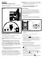
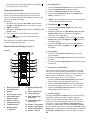
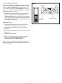
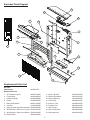
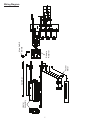
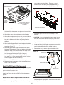
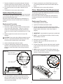
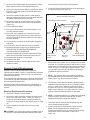
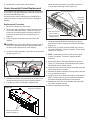
Service Manual
32” Purifire Fireplace with Full Feature Remote
Model Numbers:
DF3215 - MOD / to D
REV
Dimplex North America Limited
1367 Industrial Road Cambridge ON Canada N1R 7G8
1-888-346-7539 www.dimplex.com
In keeping with our policy of continuous product development, we reserve the right to make changes without notice.
PCN
DATE
00
~~~~
Aug 22, 07
01
11540 Jul 28, 09
7400170000rev01
Table Of Contents
Page 3 Operation
Page 6 Exploded Parts Diagram and Parts List
Page 7
Wiring Diagram and Schematic
Page 8
Light Bulb Replacement
Page 9
Purifire™ Filter Replacement
Page 9
Mirror Replacement
Page 10 Main On/Off Switch Replacement
Page 11 Switch Board Replacement
Page 11 Flicker Motor/Flicker Rod Replacement
Page 12
Remote Control Board Replacement
Page 13 Heater Assembly/Cutout Replacement
Page 14 Power Cord Replacement
2
Operation
CAUTION: If you need to continuously reset the heater,
unplug the unit and call Dimplex North America Limited at
1-888-346-7539 for technical support.
Electric Fireplace Manual Control
The manual controls for the fireplace are located in the upper
right hand corner (Figure 1).
* Not applicable on DF3215NH model fireplaces.
** Flame only function of DF3215NH
Remote Control
Figure 1
The remote control has a range of approximately 50 ft.
(15.25m). It does not have to be pointed at the fireplace
and can pass through most obstacles (including walls). It
is supplied with 243 independent frequencies to prevent
interference with other units.
SERIAL No.
XXX
Battery Installation
XX
1. Depress tab on the battery cover on the back of the
remote transmitter and remove battery cover (Figure 2).
Figure 2
Batteries
Unlocked
B
Locked
A
Initialization
Button
Child Lock Tab
Child Lock
Indicator
Light
2. Install two (2) AAA batteries into the remote control
(included).
3. Ensure child lock is in the “unlocked” position.
A. Main On/Off Switch
Supplies power to the 3 position manual control switch.
4. Replace the battery cover.
! NOTE: When the
B. 3 Position Manual Control Switch
Remote (left position): The unit is operated with the remote
control.
Flame (center position): The flame effect is turned ON.
* * Flame & Heat (right position): The flame effect and
heater are turned ON simultaneously. When the manual
control is in the Flame & Heat position the heater does not
run on the remote operated thermostat. When the heater is
ON the red indicator light is activated on the firebox and the
fan and heater are running on low.
symbol is present on the
remote control it is recommended to replace the batteries
promptly, to maintain full functionality of the remote/
fireplace. The remote transmitter has a battery backup
time of only several hours.
Initializing The Remote Control
1. Plug cord into 120 Volt wall outlet.
2. Ensure the Main On/Off switch located in the switch box
in the fireplace in the upper right hand corner is in the On
position.
3. Set the 3 position manual control to the Remote position
(left position).
4. Press and hold the initialization button on the unit.
5. While holding the initialization button, press the Flame/
Heat On/Off button or the Purifire™ On/Off button on
the remote control transmitter.
6. Release the initialization button on the unit.
! NOTE: When the manual control switch is in the Flame
and Flame & Heat positions, the fireplace unit will not
operate with the remote control.
Resetting The Temperature Cutoff Switch *
Should the heater overheat, an automatic switch will turn the
heater off and it will not come back on without being reset.
The temperature cutoff switch can be reset by unplugging the
unit, waiting 5 minutes and plugging the unit back in.
7. Press the Flame/Heat On/Off button
3
to turn the Flame/
2. Set Temperature*
Heat function On or press the Purifire™ On/Off button
to turn the Purifire™ function ON.
1.
2.
3.
4.
Frequency Interference
If the fireplace does not respond properly to the remote
control, the remote operating frequency may have to be
reset. The remote control can send another frequency code
to the circuit board to eliminate
interference.
1. Simultaneously press the “Slow Start” button and the
“Purifire™ Low Speed” button on the remote control.
2. “CODE” will appear.
3. Release the “Slow Start” button and the “Purifire™ Low
Speed” button.
4. Press and hold the initialization button on the unit.
! * NOTE: The set temperature buttons are not operational on the DF3215NH model fireplaces.
3. Light Dimmer
Your remote will now have a different frequency
communicating with the fireplace.
Remote Control Functions (Figure 3)
Figure 3
9
11
3
4
5
6
17
1.
2.
3.
4.
5.
6.
7.
8.
9.
Room Temperature
Set Temperature*
Dimmer
Flame Speed Control
Slow Start/Fading
Embers Control
Purifier™ Speed
Temperature Down*
Temperature Up*
Dimmer Down/
Firelight Off
1. Press the 17. Flame/Heat On/Off button to turn the
Flame/Heat On.
2. Press the 12. Flame Speed Up to increase the speed of
the flame.
3. Press the 11. Flame Speed Down to decrease the speed
of the flame.
8
10
12
13
15
4. Flame Speed
1
7
5. Slow Start / Fading Embers
14
The slow start function simulates a starting fire. The slow
start function is automatically programmed for 30 seconds.
The slow start timer setting cannot be changed. The fading
embers function simulates a fire going out. The fading
embers timer can be set to 1, 5 or 10 minutes.
1. Press the 14. Slow Start Fading Embers On button to
turn the Slow Start/Fading Embers function on.
2. Press the 14. Fading Embers On button repeatedly to
set the fading embers timer time to 1, 5 or 10 minutes.
3. Press the 13. Fading Embers Off button to turn the
Fading Embers timer function off.
16
18
10.
11.
12.
13.
14.
15.
16.
17.
18.
Firelight
1. Press the 17. Flame/Heat On/Off button to turn the
Flame/Heat On.
2. Repeatedly press the 10. Light Dimmer Up or 9. Light
Dimmer Down button to decrease or increase the
brightness of the upper lights.
3. To activate the “Firelight”, continue pressing 10. Light
Dimmer Up until the “Firelight On” icon
is shown on
the display screen.
4. To shut the “Firelight” off, turn the 9. Light Dimmer
Down button until the “Firelight” icon off is shown on
the display.
5. Press the button on the remote and release the
initialization button.
2
Press 17. Flame Heat On/Off button to turn fireplace on.
Press 8. Temperature Up to raise thermostat.
Press 7. Temperature Down to lower thermostat.
Press both 8. Temperature Up and 7. Temperature
Down to change °F to °C.
Dimmer Up/Firelight
On
Flame Speed Down
Flame Speed Up
Slow Start/Fading
Embers Off
Fading Embers On/
Timer Cycle
Purifier™ Low Speed
Purifier™ High Speed
Flame & Heat On/Off
Purifier™ On/Off
6. Purifier™ Speed
Press the 18. Purifire™ On/Off button to turn the Purifire™
function On. When the Purifire™ function is On the
Purifire™ Speed symbol will flash. When off the symbol
will be solid. The default setting for the Purifire™ is set at
low speed. Press the 16. Purifier™ High Speed button
to switch to the high speed level and the Purifier™ Speed
symbol will flash more quickly. Press the 15. Purifier™ Low
Speed button to switch back to the lower speed, or Press the
18. Purifire™ On/Off button to turn the Purifire™ function
Off.
4
17.Flame / Heat On/Off Button*
Figure 4
Press the 17. Flame/Heat On/Off button to turn the Flame/
Heat function On. When the 2. Set Temperature is higher
then the 1. Room Temperature the heat will come on. To
turn the heat off, lower the 2. Set Temperature so that it’s
setting is lower then the 1. Room Temperature. The default
temperature setting is 72°F (22°C).
Unlocked
Locked
! NOTE: When using the remote control the heater runs
on a thermostat. Press the 8. Temperature Up or 7.
Temperature Down button to adjust the set temperature.
Once the desired set temperature is reached the heater
will turn Off. The heater will cycle On and Off to maintain
the desired set temperature.
Child
Lock
Child Lock (Figure 4)
1. Depress tab on the battery cover on the back of the
remote transmitter and remove the battery cover.
2. Move Child Lock tab to the right to lock the remote
transmitter.
3. Move Child Lock tab back to the left to unlock the remote
transmitter.
4. Replace the battery cover.
! NOTE: To temporarily unlock the remote transmitter
press (in order) 7. Temperature Down then 8.
Temperature Up then 9. Dimmer Down.
When the remote transmitter’s backlight is illuminated the
Child Lock is bypassed. When the backlight is off the Child
Lock is re-activated.
5
Child Lock Switch
Exploded Parts Diagram
4
3
13
7
18
5
10
11
15
6
12
1
14
7
2
17
16
Replacement Parts List
DF3215
Part Number
6902520159
Replacement Part:
1. 30” Urethane Log set
0439070100RP
2. Flicker Motor 3000240200KIT
3. Heater Assembly 2200490600RP
4. Cutout
2300200500RP
5. Main On/Off Switch 2800070700RP
6. Cord Set 4100040400RP
7. Upper & Lower Light Wire Assembly 2500200200RP
8. Wire Harness - Receiver to Log set 2500380100RP
9. Wire Harness - Receiver to Blower 2500390100RP
10. Switch Board
3000320300RP
11. Mirror - Silvered
12. Remote Transmitter 13. Remote Receiver 14. Flicker Rod 15. Purifire™ Filter
16. Fireplace Foot
17. Steel Curtain
18. Steel Curtain Rod
19. Bi-fold Doors Kit
6
5900160700RP
3000610100RP
3000320500RP
5900080700RP
0439060100RP
8800090100RP
8800240603RP
8800250400RP
6902560100RP
Heater
Assembly
Cord Set
Flicker
Motor
Remote
Receiver
Main On/Off
Switch
Wiring Diagram
7
Light Bulb Replacement
7. Pull the Flicker Rod to the far right, then bend it carefully
to free and lift the left side out of the mounting bracket.
Allow at least five (5) minutes for light bulbs to cool before
touching bulbs to avoid accidental burning of skin.
! NOTE: When removing the Flicker Rod, damage may
occur if bent excessively. If the Flicker Rod is damaged,
replace to insure proper operation.
Light bulbs need to be replaced when you notice a dark
section of the flame or when the clarity and detail of the log
ember bed exterior disappears. There are four (4) bulbs
under the log set, which generate the flames and embers,
and two (2) bulbs above the log that illuminate the log
exterior.
8. Replace bulb(s) as needed.
9. Reinstall the Flicker Rod.
10.Reconnect the log set LED wire harness.
Helpful Hints
11. Replace the log set by inserting the rear edge of the log
set and push down on the front edge of the ember bed
until it snaps into place (Figure 6).
It is a good idea to replace all light bulbs at one time if they
are close to the end of their rated life. Group replacement
will reduce the number of times you need to open the unit to
replace light bulbs. Care must be taken when removing the
log set as the log set contains LED’s and wires.
! NOTE: Ensure the log set is installed tightly under the
back ledge to prevent light leakage.
Lower Light Bulb Requirements
Figure 6
Quantity of four (4) clear chandelier or candelabra bulbs with
an E-12 (small) socket base, 60 Watt rating. Example: GE
60BC or Philips 60 CTC.
Back
Ledge
Do not exceed 60 Watts per bulb
Log
Ember bed
To access the lower light bulb area (Figure 5):
1. Disconnect power to fireplace.
2. Slide fireplace out from mantel.
Rear
Tab
3. Open the bi-fold doors and steel curtain.
4. Pull the front edge of the plastic ember bed or plastic
grate up and forward until the rear tab releases from the
ledge located at the bottom of the mirror.
Front
Edge
Side Section
12.Close steel curtain and bi-fold doors.
13.Replace fireplace into mantel.
! IMPORTANT: Only handle the log set by the ember bed.
Upper Light Bulb Requirements
! NOTE: Log set fits tightly into firebox, some force may
Quantity of two (2) clear chandelier or candelabra bulbs with
an E-12 (small) socket base, 25 Watt rating.
be necessary to remove.
Do not exceed 25 Watts per bulb
5. Set log set in front of fireplace.
To access the upper light bulb area (Figure 7):
6. Disconnect the log set LED wire harness from unit
(Figure 5).
1. Open bi-fold doors and steel curtain.
2. Upper bulbs are located in the upper left and upper right
corners of fireplace.
Figure 5
Figure 7
Light Bulb
Upper Light
LED Wire
Harness
Screw
Log Set
Light
Bracket
8
2. Lay fireplace on its back.
3. Remove the light cover for each bulb (one (1) Philips
screw each).
3. Remove the 10 Philips screws that attach the bottom
panel to the fireplace as shown in Figure 9. There are:
two (2) screws along the bottom edge of each side;
two (2) screws immediately behind the front trim piece;
and two (2) screws along the back, bottom edge of the
fireplace.
4. Unscrew bulbs counter clockwise.
5. Insert new bulbs.
6. Re-install upper light bracket.
7. Close steel curtain and bi-fold doors.
Purifire™ Filter Replacement
Figure 9
To replace filter:
1. Open the bi-fold doors.
2. Remove the three (3) mounting screws from the air filter
bracket (Figure 8).
3. Remove the air filter bracket assembly from the firebox.
4. Slide filter out of air filter bracket.
5. Reassemble in reverse order as above.
! NOTE: Use caution when removing bottom panel as
Rear view of fireplace
The Purifire™ filter supplied in the fireplace is reusable
and washable. The filter should be cleaned or replaced
on average once a year. To clean the filter gently tap filter
on a hard surface to dislodge any loose dirt or debris,
and then clean with water. No soap or cleaning products
are recommended. The filter size is 20” X 10” X 1” rated
at MERV 10. If using an after market filter follow the
manufacturers recommended replacement instructions.
there are components attached to the panel which are
hard wired within the fireplace chassis.
! NOTE: The bi-fold doors are supported by the bottom
panel. When pulling the bottom panel away from the
chassis, do so carefully so that the doors do not get
damaged.
4. Carefully remove bottom panel from fireplace and swivel
it outwards to the right so as to keep wiring connected
but allowing sufficient room to work.
Figure 8
Air
Filter
5. Slide the bi-fold doors out of the top frame track and set
aside.
Air Filter
Bracket
6. Disconnect the log set LED wire harness.
7. Remove the six (6) Philips screws that hold the log set
support bracket in place. Refer to Figure 10 for a side
view of the fireplace showing screw locations.
! NOTE: Some fireplaces have these three points riveted
Mounting
Screws
instead of screwed in place. If this is the case, use a 1/8
inch drill bit to drill out the rivet.
Figure 10
Mirror Replacement
Front of
Fireplace
If the fireplace was operating prior to servicing allow at least
10 minutes for light bulbs and heating element to cool off to
avoid accidental burning of skin.
Disconnect power before attempting any maintenance or
cleaning to reduce the risk of electric shock or damage to
persons.
3 Screws to remove (per side)
8. Remove the log set and set aside.
Replacement Procedure
9. Referring to Figure 11, the sides of the log set support
bracket are aligned within the rubber extrusions of the
1. Slide fireplace out from mantel.
9
cover to the rest of the firebox. There are: three (3)
screws on each side along the top edge; and two (2)
screws on the back along the top edge (Figure 12).
Figure 11
Mirror
Rubber Extrusions
Figure 12
Log Set
Support
Bracket
These edges of bracket
slide into grooves of
extrusions
Top Section of Fireplace
Steel Curtain, Log Set and Bottom Panel removed for clarity
fireplace. Slide the bracket directly out the bottom of the
fireplace and set aside.
3. Flip the top panel over and rest it on the top of the
fireplace.
10.Slide Mirror down and out the bottom of the fireplace.
11. Align sides of replacement Mirror with grooves of rubber
extrusions and with brick effect facing out towards the
front of the fireplace, slide Mirror up into the fireplace.
The Mirror should slide into a holding track just beneath
the filter.
CAUTION: Use caution when flipping top panel over as
there are components attached to the top panel which
are wired to the internal cavity of the fireplace.
4. Open the bi-fold doors and steel curtain.
5. Locate the Main On/Off Switch mounted on the top of the
fireplace on the right side (Figure 13) and disconnect the
two (2) wiring clips noting their original locations.
6. Depress the two (2) retainer clips on the sides of the
12.Slide Log Set Support Bracket back into place, the sides
of the bracket lining up with the grooves of the rubber
extrusions (Figure 11).
13.Reinstall Log Set while support bracket is loose within
fireplace. The back edge of the Log Set should fit under
the bottom edge of the Mirror, and the front edge of the
Log Set should fit in behind the top, inside edge of the
Log Set Support Bracket (see Figure 6, page 8).
Figure 13
14.Install Log Set Support Bracket using the six (6) screws
from step 7 (or, if rivets were originally in place, use the
screws supplied with RP kit for Mirror).
Black wire to
Power Cord
Orange wire to
Circuit Board
15.Reconnect the LED Wire Harness for the Log Set.
16.Reassemble the bottom panel of the fireplace following
steps 1-5 in reverse order.
Main On/Off
Switch
Main On/Off Switch Replacement
If the fireplace was operating prior to servicing allow at least
10 minutes for light bulbs and heating element to cool off to
avoid accidental burning of skin.
Disconnect power before attempting any maintenance or
cleaning to reduce the risk of electric shock or damage to
persons.
Retainer Clip
Main On/Off Switch Replacement Procedure:
switch and push the switch through the sheet metal and
into the fireplace display cavity. Remove from the front of
the fireplace
1. Remove the firebox from the mantel.
2. Remove the eight (8) Philips screws that fasten the top
10
7. Properly orientate the new switch and push it through
the sheet metal from inside the firebox. Push until the
retainer clips on either side of the switch snap into place.
8. Re-connect the two (2) wire clips to the back of the
switch.
9. Reassemble in the reverse order as above.
7. Properly orientate the new Switch Board, snap onto
the mounting studs and reconnect the ribbon cable as
before.
8. Reassemble in the reverse order as above.
Flicker Motor/Flicker Rod Replacement
If the fireplace was operating prior to servicing allow at least
10 minutes for light bulbs and heating element to cool off to
avoid accidental burning of skin.
Disconnect power before attempting any maintenance or
cleaning to reduce the risk of electric shock or damage to
persons.
Switch Board Replacement
If the fireplace was operating prior to servicing allow at least
10 minutes for light bulbs and heating element to cool off to
avoid accidental burning of skin.
Disconnect power before attempting any maintenance or
cleaning to reduce the risk of electric shock or damage to
persons.
Replacement Procedure:
1. Slide fireplace out from mantel.
Replacement Procedure
2. Open the bi-fold doors and steel curtain.
1. Remove the firebox from the mantel.
2. Remove the eight (8) Philips screws that fasten the top
cover to the rest of the firebox. There are: three (3)
screws on each side along the top edge; and two (2)
screws on the back along the top edge (Figure 12, Page
10).
3. Flip the top panel over and rest it on the top of the
fireplace.
3. Pull the front edge of the plastic ember bed or plastic
grate up and forward until the rear tab releases from the
ledge located at the bottom of the mirror (Figure 5,
Page 8).
! IMPORTANT: Only handle the log set by the ember bed.
! NOTE: Log set fits tightly into firebox, some force may
be necessary to remove.
CAUTION: Use caution when flipping top panel over as
there are components attached to the top panel which
are wired to the internal cavity of the fireplace.
4. Set log set in front of fireplace.
5. Disconnect the log set LED wire harness from unit
(Figure 5, Page 8).
4. Open the bi-fold doors and steel curtain.
5. Locate the Switch Board mounted on the top of the
fireplace on the right side (Figure 14) and disconnect
the one (1) wide white ribbon cable noting its original
location.
6. Pull the Flicker Rod to the far right, then bend it carefully
to free and lift the left side out of the mounting bracket
(Figure 15).
! NOTE: When removing the Flicker Rod, damage may
occur if bent excessively. If the Flicker Rod is damaged,
replace to insure proper operation.
Figure 14
Wide white ribbon
cable to Circuit Board
Figure 15
Flicker Rod
Switch Board
Mounting
Studs (2)
Flicker
Motor
Screws
(2)
6. The Switch Board is fastened to the sheet metal by
two (2) mounting studs, one on each side (Figure 14).
Squeeze both mounting stud’s clasp to release and
remove the Switch Board.
Exploded view used for clarity
11
7. Remove Flicker Rod (replace and reassemble if Flicker
Motor does not need to be changed at this point).
are wired to the internal cavity of the fireplace.
4. Locate the Remote Control Receiver on the right side of
the upturned top panel (Figure 16).
8. Before removing the Flicker Motor, cut the Flicker Motor
wires (five (5) in total) close to the Flicker Motor end
with wire cutters.
9. Remove the rubber bushing from the motor shaft by
applying needle nose pliers to the motor shaft and twist
the rubber bushing off of the motor shaft.
10.Remove the motor by unscrewing the two (2) Philips
screws that attach the motor to the mounting bracket
(Figure 15).
11. Discard old Flicker Motor.
Figure 16
View of underside of Top Panel
White Wire to Heater Assembly
12.Pick up new Flicker Motor and cut wire leads to 3 1/2
inch long with wire cutters.
13.Using one of the supplied wire connectors from the
Replacement Part Kit, place one (1) yellow wire from
the new Flicker Motor and the yellow wire cut in step 9
into each terminal.
14.Secure the wire connector by crimping the 3M symbol
with pliers.
15. Pull on end of wires to ensure a strong connection.
16. Repeat the process for the four (4) remaining wires.
ENSURE THAT ALL WIRES ARE PAIRED BY
COLOUR IN EACH CONNECTOR.
17.Properly orientate and secure the replacement Flicker
Motor to the bracket with screws removed in step 10.
18.Replace rubber bushing on motor shaft.
19.Replace Flicker Rod.
20.Reassemble firebox in reverse order as above and
replace in mantel.
Antenna
Wire
White ribbon
cable to Switch
Board
Cable Connectors (4)
Black Wire to
Power Cord
Mounting
Studs (7)
Orange Wire to
Main On/Off Switch
5. Remove the one (1) white, one (1) orange, one (1) black
wire lead, four (4) cable connectors and the one (1) white
ribbon cable from the Remote Control Receiver Board as
shown in Figure 16, noting their original locations. The
four (4) cable connectors all use different sized plugs,
reinstallation will not be difficult.
Remote Control Replacement
Remote Control hand held transmitters require no
replacement procedure however, a reinitialization procedure
may need to be followed. Refer to Page 3 for the Remote
Initialization procedure.
If the fireplace was operating prior to servicing allow at least
10 minutes for light bulbs and heating element to cool off to
avoid accidental burning of skin.
Disconnect power before attempting any maintenance or
cleaning to reduce the risk of electric shock or damage to
persons.
! NOTE: The Antenna Wire is permanently attached to
the fixed daughter card of the Remote Control Receiver
Board (Figure 16). Do not attempt to remove.
6. The Remote Control Receiver Board is fastened to the
underside of the top panel by seven (7) Mounting Studs,
one (1) in each corner, and three (3) down off center
as shown in Figure 16. Either squeeze each mounting
stud’s clasp to release, or use side cutters to cut and
remove each of the Mounting Studs on the board.
Receiver Replacement Procedure:
1. Remove the firebox from the mantel.
2. Remove the eight (8) Philips screws that fasten the top
cover to the rest of the firebox. There are: three (3)
screws on each side along the top edge; and two (2)
screws on the back along the top edge (Figure 12, Page
10).
3. Flip the top panel over and rest it on the top of the
fireplace.
! NOTE: If mounting studs are cut, replacement mounting
studs will need to be inserted through the top panel.
Replacement Mounting Studs are supplied.
7. Clear both ends of each cut Mounting Stud from the
control board and the top panel.
8. Properly orientate the new Remote Control Receiver
Board, run the Antenna Wire out the side of the
fireplace as it had been and re-connect all of the wiring
connections (refer to notes taken in step 5 and
Figure 16).
CAUTION: Use caution when flipping top panel over as
there are components attached to the top panel which
12
9. Reassemble in the reverse order as above.
Heater Assembly/Cutout Replacement
Heater Assembly and panel in one hand, remove the
four (4) heater mounting screws (Figure 18).
Figure 19
If the fireplace was operating prior to servicing allow at least
10 minutes for light bulbs and heating element to cool off to
avoid accidental burning of skin.
Disconnect power before attempting any maintenance or
cleaning to reduce the risk of electric shock or damage to
persons.
White wire
to Remote
Control
Board
Replacement Procedure
1. Remove the firebox from the mantel.
2. Remove the eight (8) Philips screws that fasten the top
cover to the rest of the firebox. There are: three (3)
screws on each side along the top edge; and two (2)
screws on the back along the top edge (Figure 12,
Page 10).
3. Flip the top panel over and rest it on the top of the
fireplace.
Cutout
White wire from left
side of Cutout to
bottom terminal of
Heater Element
7. Carefully separate the Heater Assembly from the top
panel as the Cutout is mounted to the Heater Assembly
(Figure 19).
8. Remove one (1) Philips screw that holds the Cutout to
the Heater Assembly - replace if required. Follow wiring
reference in Figure 19.
CAUTION: Use caution when flipping top panel over as
there are components attached to the top panel which
are wired to the internal cavity of the fireplace.
4. Locate the Heater Assembly in the center of the upturned
top panel (Figure 17).
Figure 17
! NOTE: Reassemble in reverse order from this point
if repair is complete. Continue if replacing Heater
Assembly.
Heater Assembly
9. Remove the three (3) Mounting Brackets as shown in
Figure 19. Each bracket will be attached to the Heater
Assembly by two (2) Philips screws.
10.Attach the Cutout to the new Heater Assembly using the
same screw removed in step 8.
11. Reattach the Heater Assembly to the top panel using the
four (4) screws from step 6.
12.Using Figure 20 as a reference as well as notes made in
step 5, reconnect the six (6) wire connections between
the Heater Assembly and Remote Control Board.
13.Reattach the Top Panel to the fireplace using the eight
(8) screws removed in step 2.
14.Insert fireplace back into mantel.
5. Disconnect all six (6) wire connections at the side of the
Heater Assembly, noting all of their original positions.
6. Turn the top panel over and while supporting the
Figure 18
Mounting Brackets (3)
Top section of fireplace
Screws to remove for
Heater Assembly (4)
13
Figure 20
Black wire from front
terminal of element to P2
White wire looped from right terminal
of motor to upper terminal of element
Long white wire
from Cutout
White wire
from Cutout
to top middle
terminal of
element
Red wire from
motor’s upper
left terminal
to P1
Blue wire from
motor’s lower
left terminal
to P3
Black wire from lower back
terminal of element to P4
P1
P2
P3
P4
Enlarged view of Heater Assembly and Remote Control Board
Power Cord Replacement
Figure 20
If the fireplace was operating prior to servicing allow at least
10 minutes for light bulbs and heating element to cool off to
avoid accidental burning of skin.
Disconnect power before attempting any maintenance or
cleaning to reduce the risk of electric shock or damage to
persons.
Clamp
Neutral black
wire from
power cord
(ribbed side) to
N terminal of
Remote Control
Board
Replacement Procedure:
1. Remove the firebox from the mantel.
2. Remove the eight (8) Philips screws that fasten the top
cover to the rest of the firebox. There are: three (3)
screws on each side along the top edge; and two (2)
screws on the back along the top edge (Figure 12,
Page 10).
3. Flip the top panel over and rest it on the top of the
fireplace.
Live black wire
from power cord
(smooth side) to
bottom terminal
of Main On/Off
Switch
access panel and secure with clamp.
8. The wide blade of the power plug is designed to be
neutral and is connected to the cord side with ridges in
the rubber of the cord. Connect this side of the Power
Cord to the Neutral (N) terminal of the Remote Control
Board.
The other side of the Power Cord will have stamped
writing in the rubber sheath and is live. Connect this side
of the Power Cord to the bottom terminal of the Main On/
Off Switch.
9. Reassemble firebox
10.Replace firebox back into mantel and plug in.
CAUTION: Use caution when flipping top panel over as
there are components attached to the top panel which
are wired to the internal cavity of the fireplace.
4. Disconnect the two (2) wire connections leading from the
existing power cord. One (1) leads to the bottom terminal
of the Main On/Off Switch, the other leads to the Neutral
terminal on the Remote Control Board mounted to the
underside of the Top Panel (Figure 21).
5. Using pliers, squeeze the sides of the plastic wire clamp
on the inside of the fireplace and push it, and the power
cord through the chassis (Figure 21).
6. Release clamp from power cord and remove cord from
fireplace.
7. Feed replacement power cord through opening in the
14