1
9. Reassemble in the reverse order as above.
Heater Assembly/Cutout Replacement
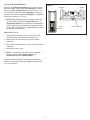
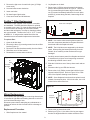
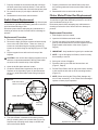
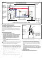
Heater Assembly and panel in one hand, remove the
four (4) heater mounting screws (Figure 18).
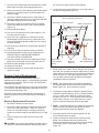
Figure 19
If the fireplace was operating prior to servicing allow at least
10 minutes for light bulbs and heating element to cool off to
avoid accidental burning of skin.
Disconnect power before attempting any maintenance or
cleaning to reduce the risk of electric shock or damage to
persons.
White wire
to Remote
Control
Board
Replacement Procedure
1. Remove the firebox from the mantel.
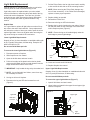
2. Remove the eight (8) Philips screws that fasten the top
cover to the rest of the firebox. There are: three (3)
screws on each side along the top edge; and two (2)
screws on the back along the top edge (Figure 12,
Page 10).
3. Flip the top panel over and rest it on the top of the
fireplace.
Cutout
White wire from left
side of Cutout to
bottom terminal of
Heater Element
7. Carefully separate the Heater Assembly from the top
panel as the Cutout is mounted to the Heater Assembly
(Figure 19).
8. Remove one (1) Philips screw that holds the Cutout to
the Heater Assembly - replace if required. Follow wiring
reference in Figure 19.
CAUTION: Use caution when flipping top panel over as
there are components attached to the top panel which
are wired to the internal cavity of the fireplace.
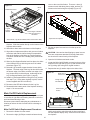
4. Locate the Heater Assembly in the center of the upturned
top panel (Figure 17).
Figure 17
! NOTE: Reassemble in reverse order from this point
if repair is complete. Continue if replacing Heater
Assembly.
Heater Assembly
9. Remove the three (3) Mounting Brackets as shown in
Figure 19. Each bracket will be attached to the Heater
Assembly by two (2) Philips screws.
10.Attach the Cutout to the new Heater Assembly using the
same screw removed in step 8.
11. Reattach the Heater Assembly to the top panel using the
four (4) screws from step 6.
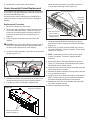
12.Using Figure 20 as a reference as well as notes made in
step 5, reconnect the six (6) wire connections between
the Heater Assembly and Remote Control Board.
13.Reattach the Top Panel to the fireplace using the eight
(8) screws removed in step 2.
14.Insert fireplace back into mantel.
5. Disconnect all six (6) wire connections at the side of the
Heater Assembly, noting all of their original positions.
6. Turn the top panel over and while supporting the
Figure 18
Mounting Brackets (3)
Top section of fireplace
Screws to remove for
Heater Assembly (4)
13