1
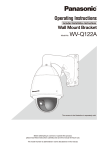
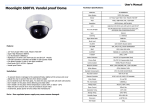
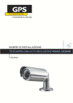
microBus-Cam II
Installation and Operation Manual
Thank you for choosing the microBus-Cam II®. This combination of a digital recorder,
camera and microphone into one package is a breakthrough in size, cost and convenience.
Totally solid-state, with no moving parts, the microBus-Cam II® records to an SD (secure
digital) memory card for ultimate reliability in all weather and road conditions.
This manual provides a source for easy navigation and setup of the product features and
operation. Here, you can set:
•
•
•
•
•
On-screen and recorded Time and Date stamps.
Recording quality.
Recording speed.
Recording schedule.
Whether to overwrite or stop recording when memory is full.
Please refer to the individual sections for complete details on each phase of use.
microBus-Cam II
Table of Contents
1.0 Mechanical Installation............................................................................................................. 3
2.0 Product Features...................................................................................................................... 4
2.1 Status LEDs.......................................................................................................................................... 5
3.0 Electrical Connections............................................................................................................. 6
4.0 Remote Control Layout............................................................................................................ 7
5.0 Screen Layouts......................................................................................................................... 8
5.1 Standby (Live) Mode............................................................................................................................ 8
5.2 Record Mode......................................................................................................................................... 8
6.0 Image Setup............................................................................................................................... 9
7.0 Recording Setup..................................................................................................................... 11
7.1 Scheduling.......................................................................................................................................... 11
8.0 Continuous Record Mode (Rewrite)......................................................................................14
9.0 Clip Length Select...................................................................................................................14
10.0 Motion Detection...................................................................................................................15
11.0 Recording Mode.................................................................................................................... 17
12.0 Playback................................................................................................................................ 18
13.0 System Settings.................................................................................................................... 19
14.0 Working with Clips--The SD Card........................................................................................21
15.0 Post Trip Delay...................................................................................................................... 22
16.0 Specifications & Features....................................................................................................23
2
microBus-Cam II
1.0 Mechanical Installation
1. Mount the support bracket to the bulkhead or ceiling of the vehicle, using the
sheet-metal screws (provided). Position the bracket at the horizontal center of
the vehicle. If the bracket is to be bulkhead-mounted, then position the bracket
as high as possible on the bulkhead. If the bracket is being mounted to the
ceiling, then mount the bracket as far forward as possible. These mounting
practices will provide optimal sight-lines.
2. Mount the microBus-Cam II® unit to the support bracket with the two 8-32
machine screws (provided). Ensure that the Camera Lens is to the left, as
viewed from the front.
3
microBus-Cam II
2.0 Product Features
Mic
Camera
Lock
A/V Jack
Status
LEDs
Remote
Sensor
SD Card
Cover
4. To access the SD Card Socket:
1. Unscrew Lock, using the key
2. Pivot the cover open
3. Push to Install / Remove SD Card
4
microBus-Cam II
2.1 Status LEDs
LED Number
Steady
Flashing
1
Menus
Playback Active
2
Preview
Reading SD Card
3
--
Recording
4
Power
Power
5
microBus-Cam II
3.0 Electrical Connections
Access the Power Connector from the Rear of the Unit
Connect each wire as indicated by the diagram. Make sure that the battery connection is
to a constant source of +12 VDC power, and fuse the +12 VDC wire at a maximum of 2A.
That's it! You're done with the installation.
Finally, plug the AV Adaptor (provided) into the A/V jack that is located below the camera.
Insert your standard RCA-type A/V cable to connect to your desired video monitor or TV (it
must be equipped with A/V inputs, of course).
When the unit has been powered, you will see a live image in your monitor. That will help
you to position the unit for the desired view, and to adjust the focus accordingly.
If you need to adjust the focus, then lightly grasp the lens and rotate it slightly, while
confirming focus in your attached monitor.
6
microBus-Cam II
4.0 Remote Control Layout
Buttons
Functions
▲
Up / Volume up (during playback)
▼
Down / Volume down (during playback)
◄
Left / Fast Forward (during playback)
►
Right / Fast Rewind (during playback)
OK
Confirm / Record (during playback)
MENU
P/P
STOP
ESC
Activate Menu
Play / Pause playback / Delete file
Stop
Return to Previous Menu or Clip
7
microBus-Cam II
5.0 Screen Layouts
5.1 Standby (Live) Mode
5.2 Record Mode
8
microBus-Cam II
6.0 Image Setup
9
microBus-Cam II
10
microBus-Cam II
7.0 Recording Setup
7.1 Scheduling
11
microBus-Cam II
12
microBus-Cam II
13
microBus-Cam II
8.0 Continuous Record Mode (Rewrite)
9.0 Clip Length Select
14
microBus-Cam II
10.0 Motion Detection
15
microBus-Cam II
16
microBus-Cam II
11.0 Recording Mode
NOTE: Use only Manual and Scheduled Settings for Vehicles.
17
microBus-Cam II
12.0 Playback
18
microBus-Cam II
13.0 System Settings
19
microBus-Cam II
Note: The GPS function is reserved for future versions. Use the TIME selection to
enable/disable the display and recording of the time-stamp. The ENABLE setting is highly
recommended.
When you have finished programming, press MENU to save and exit to LIVE MODE. When
the Ignition is activated, the unit will start recording with your new settings.
20
microBus-Cam II
14.0 Working with Clips--The SD Card
The recorded video clips are stored on a totally solid-state SD (Secure Digital) Card. The
microBus-Cam II® can accept SD Cards with capacities up to 32 GB.
Most users prefer to use a computer to view their clips. It is more convenient than onvehicle viewing— just remove the card and plug it into the SD Card reader on your
computer. Most recent computers have such readers already built in, but if yours does
not, a very inexpensive reader can be purchased at your local computer store (or us). The
readers use the computer's USB 2.0 port to adapt to the SD Card.
Important:
Before proceeding with SD Card removal , stop all recording by pressing the
'STOP' button on the Remote Control, and wait for the green record light to go
off. Failure to stop recording before removing the SD Card can corrupt it.
To remove the SD Card from the microBus-Cam II®, use the provided key to disengage
the lock next to the card, then swing the SD Card cover away from the opening..
Next, push the SD Card toward the unit, then release it--the card will disengage.
Reverse the procedure to install a new card.
Note:
Make sure that your computer has the latest video codecs installed. Free codecs are available
for download at www.divx.com. They also have some excellent video players at a nominal
cost, but the standard Windows Media Player is perfectly capable of playing clips from the
microBus-Cam II®
(with the proper codecs, of course).
High-quality video playback of any kind requires a good-quality video graphics card and USB
2.0 port on your computer.
21
microBus-Cam II
15.0 Post Trip Delay
This feature provides the ability to continue recording for a set period--even after the
Ignition (or other trigger source) is turned off.
The time delay setting can be made with the 3-position DIP switch that is located on the
rear of the unit. Simply use a small screwdriver or pen to slide the small switches into the
OFF or ON positions. We have provided a table of time delays (in minutes) and the switch
settings that correspond to those delays (see below). You can choose among the following
values: 1, 2, 3, 5, 10, 20 or 30 minutes.
DIP Switch
Position 1
Time (minutes)
Switch
1
2
3
0 (No Delay)
OFF
OFF
OFF
1
ON
OFF
OFF
2
OFF
ON
OFF
3
ON
ON
OFF
5
OFF
OFF
ON
10
ON
OFF
ON
20
OFF
ON
ON
30
ON
ON
ON
22
microBus-Cam II
16.0 Specifications & Features
For DVR
Parameter
Compression Standard
MPEG-4 / H.264
Resolution
Full D1 (704 x 576)
Video Format
MPEG-4/ASF
Audio Format / Rate, Encoding
MP3 / 8KHz,ADPCM
Frame Rate
User-selectable, 5/15/30
Storage Medium
SDHC Memory Card, Max. 32 GB
Playback
Composte NTSC
User Control/Setup
Via Infrared Remote Control (provided)
Wide Operating Voltage Range
5-35V DC
Low Power Consumption
Standby: 1W / Recording: 2W
Stability
Built-in Watch Dog Circuit
Automatic Operation
On Ignition Trigger (or other 12VDC source) or with
Ignition Trigger + Schedule.
For Camera
Parameter
Image Sensor
Sony 1/3”
CCD + DSP
Sony 672AK + Sony Effio-E Image Processor
Horizontal Resolution
700TVL, Low Illumination, DWDR, OSD, DNR
Pixels
NTSC, 976H x 582V
TV System
NTSC
Usable Illumination
0.001 Lux / F2
S/N Ratio
≥ 115 dB, AGC Off
Gamma Correction
0.45
Video Out
NTSC Composite (1Vp-p @ 75 Ohms)
Scanning System
NTSC 525 Lines, 60 Fields/Second
Electronic Shutter Speed
1/60 Second to 1/100,100 Second
General
Parameter
Dimension (without Bracket)
5.75” L x 3.25” W x 1/25” H
Operating Voltage
5 – 32 VDC
Operating Temperature
15°F to 122°F
Enclosure Composition, Compliance
ABS / UL 94 HB
Enclosure Tensile Strength
6530 psi
microBus-Cam II® is a product of Robotics Technologies, Inc. All material and information contained herein
are Copyright 2013, with all rights reserved. Please visit our website, www.roboticstech.com, for current warranty,
policy and technical information.
23