1
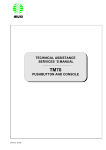
THE ORANGE BOOK operator’s guide PSL1569 issue 1 Contents Introduction Welcome XL Multiphase panel layout XL signal head panel layout Installation XL signal heads Checking whether a head can be used Upgrading earlier XL signal heads Setting up the heads and controller Phase set up examples 2 2 3 4 5 5 5 5 6 8 Operation Making adjustments Operation modes Calling ‘hold all red’ from a signal head Resetting the system Decommissioning the system Incidents during operation Error indications Troubleshooting Fuse replacement Further information Control panel rear connections Specifications Power requirements Warranty Disclaimers Environmental information 13 13 13 14 14 15 15 16 17 18 19 19 19 19 20 20 20 release 1.0g Introduction Welcome Thank you for choosing the XL Multiphase Controller which allows you to orchestrate up to eight wireless signal heads controlling a maximum of four separate traffic phases. Using sophisticated radio links and integral failsafe measures, the XL Multiphase system lets you quickly and safely install junction control without the complication of cables. Although powered by advanced technology within, outwardly the XL Multiphase Controller has a panel with a conventional appearance and logical layout. This allows you to quickly apply settings and then to easily monitor every aspect of the system in operation. Secure radio links The XL Multiphase Controller can maintain radio communication with up to eight remote signal heads located up to 500 metres away (line of sight). The XL Multiphase Controller is fully type approved to Highways Agency specification TR2502 and is manufactured in the UK in accordance with ISO 9001 Quality Assurance procedures. XL Multiphase Controller 2 Direct connection The primary signal head can be optionally connected directly to the XL Multiphase Controller. XL Multiphase panel layout The control panel of the XL Multiphase Controller is arranged logically for ease of set up and use. General items are located in the lower section of the panel while controls PHASE 1 specific to each phase are placed in four identical groups. XL MULTIPHASE CONTROLLER DEMAND 45 ALL RED 50 PHASE 1 All red dial Sets the time (in seconds) that all signal heads must remain on red before the next phase can begin its amber/ green cycle (see page 11). Maximum green dial Sets the time (in seconds) that this phase will show green during a normal cycle of operation (see page 11). Phase on/off button Use this button to enable or disable this phase within the current set up (see page 11). 45 ALL RED 50 DEMAND 1 40 5 30 10 25 20 15 PHASE 2 30 DEMAND 5 40 30 15 20 ALL RED 50 45 MAXIMUM GREEN 60 55 15 4050 20 45 25 30 40 25 50 20 45 25 40 35 DEMAND 30 PHASE ON/OFF ON/OFF Phase mode This section determines the number of heads and their MANUAL function within this phase (see HOLD ALL RED page 11). RUN Demand button MAXIMUM GREEN When the60 mode switch 55 15 is set to MANUAL, this 50 20 button simulates the microwave vehicle de45 25 tector being triggered for that phase. When 40 30 35 chosen pressed, the phase will change to green after all others PHASE have been set to red (see page 12). Low battery indicator ON/OFF Illuminates to warn that one or both of the remote heads on this phase are getting low onVEHICLE battery charge (see page 16). FIXED TIME 45 5 40 10 30 15 50 20 45 25 15 40 35 30 DEMAND 45 40 DEMAND 30 20 ALL RED 50 45 5 40 10 30 45 25 35 30 DEMAND 1 5 10 20 15 DEMAND 1 20 ALL RED 50 25 MAXIMUM GREEN 60 55 15 25 PHASE 20 ON/OFF 15 50 40 PHASE 4 1 PHASE 4 PHASE ON/OFF ALL RED 50 25 MAXIMUM GREEN 60 55 15 5 DEMAND MAXIMUM GREEN 60 55 15 5 DEMAND 50 20 45 10 15 DEMAND 25 40 35 30 PHASE ON/OFF ON/OFF ON/OFF SERIAL NUMBER: MANUAL MAXIMUM GREEN 60 55 15 20 PHASE 3 DEMAND 1 DEMAND 10 20 ALL RED 50 25 1 30 35 PHASE 45 10 PHASE 3 25 PHASE 2 1 40 Signal head mimic These indicators show the signals ALL RED given currently being 50 at the 1 this 45head(s) for phase (left side = pri40 5 mary head; right side = secondary head). 30 10 The top (demand) indicator shows15when 25 20 the microwave vehicle detector recognises an approaching vehicle (see page 16). XL MULTIPHASE CONTROLLER HOLD ALL RED MAXIMUM GREEN 60 55 15 VEHICLE FIXED TIME RUN DEMAND 50 45 20 APPROVED FOR MULTISTAGE OPERATION 25 40 PHASE ON/OFF button Press and release to switch on, press and hold for twoON/OFF seconds to switch off (see page 11). TIME SECONDS DEMAND TIME SECONDS 8888 MAXIMUM GREEN 60 55 15 50 20 45 25 DEMAND STATUS 40359 4034, WWW.PIKESIGNALS.COM 30 PIKE30 SIGNALS LIMITED, BIRMINGHAM, 0121 35 RUN button Press to begin running the programmed sequences (see page 12). 8888 35 Mode switch PHASE Timer display Expansion Selects the Counts the connector main operation elapsed time (in Reserved for mode for the seconds) within future use. system as a ON/OFF the current phase whole (see of operation. When page 13). failures occur, this displays trouble-NUMBER: SERIAL shooting codes (see page 16). PSL1481 iss 1 Status indicator Displays green or red to indicate the current status of operation (see page 16). 3 XL signal head panel layout The control panel of each XL signal head is located either at the rear of the head or within the head’s base unit. All XL signal heads must be configured before the XL Multiphase Controller begins operation. All configuration is achieved using the three blue buttons and the display screen. Display screen Indicates available options, current settings and error messages. All red call button Can be used to place the multiphase system into Hold All Red mode. Demand button Not used for multiphase operation. Signal head mimic These indicators flash if an error occurs on a different head. Demand button Not used for multiphase operation. M PLEASE SELECT ONE OF THE FOLLOWING XL TWO PHASE á MULTIPHASE S Demand indicator Shows when the microwave vehicle detector of this signal head recognises an approaching vehicle. Demand indicator Not used for multiphase operation. Power switch I/O PIKE SIGNALS LIMITED BIRMINGHAM B19 2RS MODEL: XL SERIAL NO: xxxxx TYPE APPROVED TO DoT SPECIFICATION TR 0111/A O I 12V DC Radio signal Flashes green when radio communication is OK. Flashes red to indicate a radio link problem. 4 Low battery Flashes red when battery is low. Remains on when battery is too low to continue operation. Major fault Flashes red if a major fault occurs. Switch off and return for repair. Signal head mimic These indicators show the signals currently being given at this head. Information label Models with serial numbers less than 7xxxx must be upgraded for multiphase operation. Upgraded models are handmarked with an ‘M’. Early models with serial numbers starting with 5 cannot be upgraded. Scroll and enter buttons Use to choose and confirm setup options. Installation The XL Multiphase Controller can control up to four phases of traffic, either all via wireless links or with one phase directly connected by cable and the remainder by wireless. According to the junction layout, the XL Multiphase Controller can be set to control each junction approach as a separate phase or alternatively combine both directions of a road within a single phase. XL signal heads Checking whether a head can be used There are two ways to determine the suitability of an XL signal head: Switch on and check the initial screen Check the serial number In the lower right corner of the XL signal head control panel is the serial number label. It will take one of three forms: PIKE SIGNALS LIMITED BIRMINGHAM B19 2RS MODEL: XL SERIAL NO: xxxxx TYPE APPROVED TO DoT SPECIFICATION TR 0111/A PIKE SIGNALS LIMITED BIRMINGHAM B19 2RS MODEL: XL M SERIAL NO: xxxxx TYPE APPROVED TO DoT SPECIFICATION TR 0111/A Old version Upgraded New version Must be upgraded before it can be used with the XL Multiphase Controller. See note below: Label marked by a handwritten M or with a sticker. Can be used with the XL Multiphase Controller. Serial number 7xxxx or above. Can be used with the XL Multiphase Controller. Note Models that have serial numbers beginning with 5 cannot be upgraded or used with the XL Multiphase Controller. • If this is the initial screen then the XL head IS able to operate with the XL Multiphase Controller. PLEASE SELECT ONE OF THE FOLLOWING XL TWO PHASE á MULTIPHASE • If this is the initial screen then the XL head IS NOT able to operate with the XL Multiphase Controller until it receives an upgrade. FOR LAST MODE/SET UP TIMES PRESS ENTER ßá FOR NEW MODE/SET UP TIMES PRESS SCROLL à Upgrading earlier XL signal heads Most earlier versions of XL heads (except those with 5xxxx serial numbers) can be upgraded to operate with the XL Multiphase Controller. The upgrade work must be carried out by a Pike certified engineer, either on site or at Pike Signals. Contact Pike Signals for details. 5 Setting up the heads and controller 1 Set up all signal heads, cones and signs according to Highways Agency regulations. Required reading • ‘The use of vehicle actuated portable traffic signals’ (the ‘Pink Book’) ISBN: 0115507817 • ‘Safety at street works and road works’ (the ‘Maroon Book’) ISBN: 0115519580 • ‘Traffic signs regulations and general directions’ (TSRGD) Chapter 8 ISBN: 0110429427 Attach the supplied antenna to the XL Multiphase Controller and connect a fully charged battery. Ensure that all signal head batteries are fully charged. Notes The XL Multiphase Controller should be OFF at this stage. The battery should be a ‘deep cycle’ type of no less than 105Ah capacity. If a signal head is directly connected to the XL Multiphase Controller by cable, it will automatically become the primary signal head of phase 1 (PH1áS). If a signal head is directly connected to the XL Multiphase Controller, the cable must be less than 5 metres in length and the signal lamps should be LED types. 6 2 For each approach, measure the distance from each WAIT HERE sign to the WAIT HERE sign furthest away. 3 On each remote XL signal head: I/O a O I b PLEASE SELECT ONE OF THE FOLLOWING XL TWO PHASE á MULTIPHASE Switch on the signal head at the control panel. Press á Use row S for a single or primary signal head. e Use row D for a second signal head in a phase (if used). á Press to choose ( ) the correct phase number for this head. See pages 8 to 10 for phase set up examples. Press If correct, press to proceed. to proceed. If the signal head does not display the above screen, it may not be suitable for use. See page 5. USE UP & DOWN KEYS PH1 PH2áPH3 PH4 S PH1 PH2 PH3 PH4 D PRESS ßá KEY The screen will confirm your settings. If a change is required, use to make the change, as per step c. Important c MULTIPHASE OPERATION THIS SIGNAL HEAD PHASE TWO SINGLE IF OK PRESS ßá KEY to choose ( ) MULTIPHASE. Press d to proceed. MULTIPHASE OPERATION PHASE TWO SINGLE WAITING FOR MASTER PLEASE WAIT The head is now ready and waiting for control signals from the XL Multiphase Controller. No signal lamps will be lit at this stage. Repeat for all other signal heads then go to step 4... ...continued on page 11 Notes Ensure that each XL signal head is capable of operating with the XL Multiphase Controller. See page 5 for details about how to check. If a signal head is directly connected to the XL Multiphase Controller by cable, it will automatically become the primary signal head of phase 1 (PH1áS). 7 Phase set up examples Example 1: Carriageway (2 approaches, 2 phases, 2 heads) This example shows a carriageway controlled by two single approach phases, each with one signal head. Example 2: Carriageway (2 approaches, 2 phases, 4 heads) This example shows a carriageway controlled by two single approach phases, each with nearside and offside signal heads. Offside head: Secondary Phase modes One head per approach 12 USE UP & DOWN KEYS PH1áPH2 PH3 PH4 S PH1 PH2 PH3 PH4 D PRESS ßá KEY Phase modes PH Two heads per approach PH 12 USE UP & DOWN KEYS PH1 PH2 PH3 PH4 S PH1 PH2áPH3 PH4 D PRESS ßá KEY Nearside head: Primary USE UP & DOWN KEYS PH1áPH2 PH3 PH4 S PH1 PH2 PH3 PH4 D PRESS ßá KEY E2 PH E2 PH HA S P AS AS E1 USE UP & DOWN KEYS PH1 PH2áPH3 PH4 S PH1 PH2 PH3 PH4 D PRESS ßá KEY PH AS E1 USE UP & DOWN KEYS PH1 PH2 PH3 PH4 S PH1áPH2 PH3 PH4 D PRESS ßá KEY Offside head: Secondary 8 PH PH USE UP & DOWN KEYS PH1 PH2áPH3 PH4 S PH1 PH2 PH3 PH4 D PRESS ßá KEY Nearside head: Primary D USE UP & DOWN KEYS PH1áPH2 PH3 PH4 S PH1 PH2 PH3 PH4 D PRESS ßá KEY Phase modes PH PH One head per approach PH 12 3 USE UP & DOWN KEYS PH1áPH2 PH3 PH4 S PH1 PH2 PH3 PH4 D PRESS ßá KEY E1 2 USE UP & DOWN KEYS PH1 PH2 PH3 PH4 S PH1áPH2 PH3 PH4 D PRESS ßá KEY HA S One head per approach PH USE UP & DOWN KEYS PH1 PH2áPH3 PH4 S PH1 PH2 PH3 PH4 D PRESS ßá KEY 2 1 PH A Phase modes PH Two opposed heads Example 4: T-junction control (3 approaches, 3 phases) This example shows two approaches of a main road controlled by two separate single approach phases. The side road approach is controlled by a third single-approach phase. P PH E AS AS E1 PH USE UP & DOWN KEYS PH1 PH2áPH3 PH4 S PH1 PH2 PH3 PH4 D PRESS ßá KEY 2 SE Example 3: T-junction control (3 approaches, 2 phases) This example shows two approaches of a main road controlled by one phase with opposed heads. The side road approach is controlled by a single approach phase. PH A SE SE 3 A PH 1 USE UP & DOWN KEYS PH1 PH2 PH3áPH4 S PH1 PH2 PH3 PH4 D PRESS ßá KEY 9 PH AS PH E2 10 1D 12 AS E Phase modes PH E2 E1 USE UP & DOWN KEYS PH1áPH2 PH3 PH4 S PH1 PH2 PH3 PH4 D PRESS ßá KEY PH AS AS Two opposed heads 2 SE A PH PH D USE UP & DOWN KEYS PH1 PH2 PH3 PH4 S PH1 PH2áPH3 PH4 D PRESS ßá KEY PH PH USE UP & DOWN KEYS PH1 PH2 PH3 PH4 S PH1áPH2 PH3 PH4 D PRESS ßá KEY USE UP & DOWN KEYS PH1 PH2áPH3 PH4 S PH1 PH2 PH3 PH4 D PRESS ßá KEY Note: For 2 heads per approach, set up each phase as per example 2 SE AS E1 Phase modes PH PH PH PH 4 A PH USE UP & DOWN KEYS PH1áPH2 PH3 PH4 S PH1 PH2 PH3 PH4 D PRESS ßá KEY 12 3 4 USE UP & DOWN KEYS PH1 PH2 PH3áPH4 S PH1 PH2 PH3 PH4 D PRESS ßá KEY E3 USE UP & DOWN KEYS PH1 PH2áPH3 PH4 S PH1 PH2 PH3 PH4 D PRESS ßá KEY Example 6: Crossroad control (4 approaches, 4 phases) This example shows a crossroad (or staggered junction) controlled by four separate single-approach phases. PH AS Example 5: Crossroad control (4 approaches, 2 phases) This example shows a crossroad (or staggered junction) controlled by two phases (two opposed heads). One head per approach USE UP & DOWN KEYS PH1 PH2 PH3 PH4á S PH1 PH2 PH3 PH4 D PRESS ßá KEY Setting up (continued from page 7) 4 On the XL Multiphase Controller, change the mode switch to HOLD ALL RED. 5 Press the ON/OFF but- ton to power on the XL Multiphase Controller. MANUAL HOLD ALL RED c Using the measurement taken earlier 45 (from this phase’s WAIT HERE sign to the WAIT HERE sign furthest away), set the appropriate ALL RED time: 0m 50m 5 seconds ALL RED 50 1 40 5 30 10 25 20 15 100m 10 seconds 150m 15 seconds 250m 200m 20 seconds 25 seconds 300m 30 seconds Note On steep gradients, increase the ALL RED time by 5 seconds for the uphill phase(s). 6 For each phase that will be used: to enable or disable the phase. Ensure that all unused phases are disabled. FIXED TIME ON/OFF The controller retains all of the settings from its previous installation. a Press the PHASE ON/OFF button VEHICLE PHASE ON/OFF d Using the measurement taken earlier MAXIMUM GREEN 60 55 15 (from this phase’s WAIT HERE sign to the WAIT HERE sign furthest away), set the appropriate MAXIMUM GREEN time: 50 20 45 25 40 35 30 b Press the phase mode button to choose the appropriate mode: One head per approach Two heads per approach 0m 75m 35 seconds 135m 40 seconds 195m 45 seconds 300m 50 seconds Two opposed heads See pages 8 to 10 for phase set up examples. Repeat for each active phase and then go to step 7 overleaf 11 7 Press the RUN button to begin operation. It is at this point that the XL Multiphase Controller will begin to communicate with the remote XL signal heads. 8 You can now switch to VEHICLE activated operation. RUN If traffic is tailing back significantly on one approach: a Change the mode switch to MANUAL. MANUAL LL RED VEHICLE FIXED If any communication or configuration problems exist, it is now that they will become apparent. Errors are signalled on the XL Multiphase Controller panel in three main ways: • Flashing indicators within each phase section of the control panel, • Error codes shown on the numeric TIME display, and/or • Flash codes on the STATUS indicator. Operation will not begin and the signal heads will not be lit until all communication and/or configuration problems are solved. See pages 14, 15 and 16 for details about error indications and possible remedies. When the XL Multiphase Controller is fully confident of the system integrity, the signal heads in each phase/ approach will in turn display amber and then red. b Press the DEMAND button for that approach/phase. DEMAND c Then, as the traffic starts to flow, change the mode switch to VEHICLE. VEHICLE FIXED If traffic is evenly spread among the approaches: a Change the mode switch straight to VEHICLE. Important To preserve battery power, after 20 minutes of normal operation the XL Multiphase Controller panel indicators will switch off. The backlight for the RUN button and also the STATUS indicator will remain on and normal operation will continue. To restore the indicators, press the RUN button. 12 MANUAL L RED MANUAL L RED VEHICLE FIXED Operation Making adjustments Operation modes When the system is running, continue to monitor the build up of traffic on each approach. If regular patterns of significant traffic queues are emerging on particular approaches, consider making careful adjustments to alleviate the problem. The mode switch determines how the system operates. Timing adjustments can be made to a phase at any time. The effects of timing changes will be incorporated during the next full cycle of operation for each phase. Note Introduce timing changes in small steps and one at a time. Observe the results before making any further changes. Slow moving vehicles not clearing the works If there are large numbers of slow moving vehicles which have difficulty in clearing the works before the signals have changed, increase the ALL RED settings for the affected approach(es) by 5 seconds. 45 ALL RED 50 1 40 5 30 10 25 20 15 HOLD ALL RED All signal heads are forced to red and held until the mode is changed. MANUAL HOLD ALL RED Vehicles taking more than one green period to clear the works If substantial queues begin to form and vehicles regularly take more than one green period to get through the works, increase the MAXIMUM GREEN settings for the affected approach(es) by 5 seconds. MANUAL Phases respond to the control panel DEMAND buttons - the microwave vehicle detectors of the heads are ignored. In this mode, the ALL RED time settings for each phase are used, the minimum green time is set at 12 seconds and the maximum green time is determined by the operator’s actions. Note: It is important to set the correct ALL RED time for each phase in order to prevent green signals being given too soon on opposing phases. MAXIMUM GREEN 60 55 15 50 20 45 25 40 35 VEHICLE All enabled phases use their configured timings and respond to the microwave vehicle detectors on each signal head. This is the most efficient mode of operation and should be used in most situations unless there are special circumstances. VEHICLE FIXED TIME FIXED TIME All enabled phases use only their configured timings - the microwave vehicle detectors of the heads are ignored. This is an inefficient mode of operation as it does not adapt to the prevailing traffic conditions. 30 13 Calling ‘hold all red’ from a signal head Resetting the system The multiphase system allows the ‘hold all red’ mode to be invoked from any of the remote signal heads as well as via the main control panel. This is a useful feature for: Certain failures within the XL multiphase system require the operator to cure/acknowledge the failure and reset the system as a whole. In such cases the system may be held within a special condition or remain operating in a reduced mode. • Occasional heavy plant crossings, • When the works involve temporarily blocking the shuttle lane(s), or • When traffic needs to be stopped due to an accident or incident within the works area. To call ‘hold all red’ from a remote signal head 1 On the remote signal head, press the all red call button. • All signal heads will be returned to red and will stay at red until the state is overridden. • The time display on the XL Multiphase Controller will show rrc (remote red call). • The display panel on each head will show ALL RED KEY ACTIVE. To override the ‘hold all red’ state 1 On the XL Multiphase Controller, press the RUN button. • The system will resume with the mode that was running prior to the ‘hold all red’. 14 RUN To reset the system after an error 1 Inspect the XL Multiphase Controller panel indicators to trace the problem. Pages 15, 16 and 17 provide descriptions. 2 If the problem is traced to one or more signal heads, visit each affected head and check the control panel(s). Depending on the fault: • If possible, rectify the problem and reset the signal head(s), or • Replace the signal head(s) and follow the set up instructions in step 3 (shown on page 7) to select the correct phase number(s). 3 When all affected heads have been reset, on the XL Multiphase Controller panel press the RUN button to restart operation. Monitor the system operation until you are sure that it is operating correctly. Decommissioning the system Incidents during operation When the portable traffic signals are no longer required, please follow this procedure to decommission their use: In accordance with Highways Agency specification TR2502, the XL Multiphase Controller and all associated signal heads monitor themselves continually for faults or unexpected incidents during operation. The system as a whole adheres to a defined set of responses for particular failures, as discussed here. 1 Ensure that the shuttle lanes are cleared of obstructions (with the exception of the signals heads, their cones and related warning signs). 2 Change the mode switch of the XL Multiphase Controller to HOLD ALL RED. 3 In turn, go to each approach and face the signal head away from the traffic. 4 When all signal heads have been faced away from traffic, press and hold the ON/OFF button on the XL Multiphase Controller until all indicators extinguish. 5 Remove the signal heads from the carriageways. 6 Carefully remove all cones, then the signs, all in accordance with the recommended procedures given in the guide “Safety at street works and road works” ISBN: 0115519580. Red signal failures If a red signal failure is detected on a signal head: • The green signals on all other approaches/phases will be suppressed. In other words, as any other phase begins its sequence, the green signal that should immediately follow the red/amber will be blanked. The signal head with the failed red is the only one that will continue to show green during its active cycle. All green times will be reduced to 12 seconds. • On the XL Multiphase Controller panel, the mimic indicator representing the failed red signal will flash continuously. If failed red signals are detected on more than one signal head: • All signals will be immediately blanked and the controller will stop operation. • On the XL Multiphase Controller panel, the TIME display will show StoP and the mimic indicators representing the failed red signals will flash. See Resetting the system on page 14. Green signal conflicts If opposing phases show green signals simultaneously at any time: • All signals will change directly to red (no amber signal) and all will remain at red. See Resetting the system on page 14. • On the XL Multiphase Controller panel, the TIME display will show StoP and the mimic indicator representing the signal head that incorrectly presented a green signal will flash. 15 Error indications The XL Multiphase Controller uses its various panel indicators to provide assistance in tracing and solving operational problems. Mimic indicators (for each phase) In normal operation these displays mimic the currently active lamps of each signal head with a steady illumination of the appropriate lamp colour. If a lamp fails or a green conflict is detected, the relevant indicator(s) will flash to highlight the location of the problem. The left three indicators of the mimic represent the primary signal head for a phase, the right three indicators represent the secondary head (if used). The top indicator shows when a vehicle is detected by the microwave vehicle detector (on either signal head). DEMAND Battery indicators (for each phase) The battery indicator will flash when there is roughly two hours of operational time remaining within a remote signal head battery. When the battery becomes too low for operation, the signal head will switch off and the indicator on the XL Multiphase Controller will remain on. If two heads are used within a phase, the low battery state could signify low power at either or both signal heads - the control panel on each XL signal head will provide further details. When the primary signal head and the XL Multiphase Controller are cable connected, they both use a common battery. The common battery’s low power state is signified by a bAtt message on the TIME display. Time display The four digit display at the bottom of the control panel shows a continual count of the elapsed time for the current signal of the active phase. In error situations, this display is used to provide alphanumeric status codes, as follows: TIME SECONDS 8888 Conn then CnF Connection/configuration problem with remote XL signal heads. Heads are either not configured as set up on the XL Multiphase Controller or are not available as expected. StoP Operation has been stopped due to a serious fault. Check the other panel indicators and the signal head displays to locate and remedy the fault. bAtt The battery supplying the XL Multiphase Controller is running low - roughly two hours operation or less remaining. rrc The system has entered ‘hold all red’ mode due to a request from a remote signal head. Press RUN to override. Status indicator In normal operation the status indicator will show a constant green light or other states as follows: Constant green System running correctly. Constant red System unconfigured, not running. STATUS Flashing green Attempting to locate a remote head that is registered to be available according to panel settings. Flashing red Setting/state change made at the control panel but not yet transferred to the affected signal head(s). Note: Alternate red and green flashes may be seen as attempts are made to send new settings to remote heads. 16 Troubleshooting Green mimic indicator flashing A green conflict has been detected. Reset or replace the corresponding signal head, as necessary. See Resetting the system on page 14. Red mimic indicator flashing A red lamp failure has been detected. Check and replace the affected signal lamp or head, as necessary. See Resetting the system on page 14. The Status indicator is flashing Flashing green Communications - attempting to locate a remote head that is registered to be available according to the panel settings. Flashing red Setting/state change made at the control panel but not yet transferred to the affected signal head(s). Flashing red and green Attempts are being made to transfer new control panel settings to one or more signal heads. Battery symbol flashing The indicated signal head has roughly two hours or less of operation remaining before it must shut down. Check the control panel of the affected signal head and replace its battery. Battery symbol on The indicated signal head has shut down due to insufficient battery power. Change the battery of the affected signal head. The mimic lights are not working on the controller The controller has probably entered power save mode (after 20 minutes of operation). Press the RUN button to restore the status illuminations, if required. Operation of the signal heads is not affected by the power save mode. XL Multiphase Controller does not respond to ON/OFF button A fuse may have blown within the controller. See page 18 for details. 17 Fuse replacement The XL Multiphase Controller has three fuses located on its right hand side. The control panel must be removed from its cradle in order to access the fuses. All fuses are standard automotive blade-types that are available at many outlets. To change a fuse 1 Switch off the XL Multiphase Controller, if it is still switched on - all slave signals will show red until the controller is reinstated. If traffic needs to be directed, make immediate provision of alternative controls while the XL Multiphase Controller is out of action. 2 Remove the eight cross-headed screws located in the corners of the control panel. 3 Lift the control panel carefully out of the cradle. Take care not to pull or snag the cables at the rear. 18 30 Note: The 1 amp fuse powers the Microwave Vehicle Detector (MVD) on the signal head connected directly to the XL Multiphase Controller (if used). Check the MVD on the head for indications before checking the fuse. 30 5 Place the control panel back into its cradle and replace the eight screws. 1 4 Pull out each fuse and inspect it visually (and with a meter, if necessary). If a fuse is blown, replace it with an identically rated fuse. Check all three fuses. Blade fuses: 30 amp Controller power 30 amp Controller power 1 amp MVD (see note) Further information Control panel rear connections Specifications • Type approved to Highways Agency specification TR2502 Approval number: AP14/703. A copy of the approval authorisation can be provided upon request. • Manufactured in the United Kingdom in accordance with ISO 9001 Quality Assurance procedures. Power requirements • Operating range: 10.5Vdc to 14.5Vdc • System shuts down at 10.5Vdc to protect supply batteries. • Use only deep cycle batteries with a minimum power rating of 105Ah. 19 Warranty Environmental information The XL Multiphase Controller is guaranteed against failure subject to fair wear and tear, correct operation and return to our works carriage paid. We undertake to repair or replace this equipment free of charge providing: EU directive 2002/95/EC on the Restriction of the use of certain hazardous substances in electrical and electronic equipment (RoHS) • It has been maintained in good condition and operated with due care, and • Any failures are directly traceable to faulty material or workmanship. However, we cannot entertain any claims for labour or other expenditure in connection therewith. Items or components subject to another manufacturer’s guarantee are subject to the terms of that guarantee only. Any warranty given is void if seals on equipment are subsequently found to have been broken without prior permission by Pike Signals Limited. Any item of equipment repaired by Pike Signals Limited is guaranteed from failure for three months from the date of repair, provided that the item has been subjected to fair usage and regular maintenance. Disclaimers Pike Signals Ltd reserves the right to change or alter product specifications without prior notice. The information contained within this guide is subject to copyright and may not reproduced in part or in full without prior written permission by Pike Signals Ltd. While every effort has been taken to ensure that this guide provides accurate information, no liability shall be accepted for any errors or omissions. It is a policy of Pike Signals Ltd to seek registered Design and/or Patent Protection for its products. 20 It is Pike Signal Limited’s desire to meet customer requirements with respect to the RoHS initiative. We are actively working to achieve the important objective of making our products compliant with the EU RoHS directive (and similar initiatives) through efficient product design that reduces unnecessary waste; the use of recyclable materials throughout, and a transfer to lead-free components and solder. EU directive 2002/96/EC on Waste Electrical and Electronic Equipment (WEEE) Pike Signals Limited is focused on developing a compliance program for the European Union (“EU”) Directive on Waste Electrical and Electronic Equipment, Directive 2002/96/EC. Under the EU WEEE Directive manufacturers of covered electronic equipment are obligated to take back such products at the end of their useful life. Pike Signals Limited is committed to meeting or exceeding environmental standards in the production of all products and is engaged in a comprehensive, company-wide effort towards full compliance with the EU WEEE Directive. Documentation by: www.ctxd.com 8 RADIO LINK UP TO 8 HEADS EASY SET UP BATTERY POWERED Pike Signals Limited Units 7, 9 & 11 Phoenix Business Park, Avenue Road, Aston, Birmingham, B7 4NU tel: +44(0)121 359 4034 fax: +44(0)121 333 3167 email: [email protected] www.pikesignals.com PORTABLE