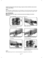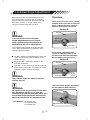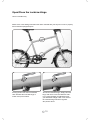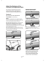
1
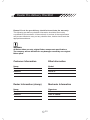
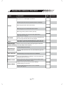
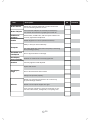
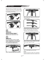
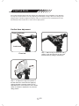
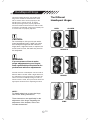
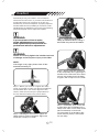
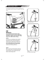
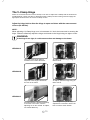
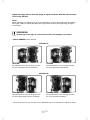
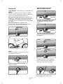
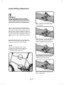
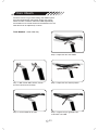
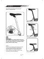
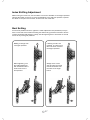
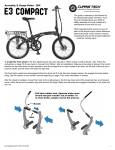
Service
Instructions
Contents
Dealer Pre-delivery Checklist .............................................................................03
VRO Stem ..................................................................................................................07
Flat Pak Stem ...........................................................................................................08
Handlepost Hinge ..................................................................................................10
Headset .......................................................................................................................12
Frame Latch ..............................................................................................................13
LockJaw Hinge Adjustment ...............................................................................17
Kore I-Beam ..............................................................................................................22
Dahon Neos Derailleur .........................................................................................23
02
Dealer Pre-delivery Checklist
Please fill out the pre-delivery checklist to activate the warranty.
This following pre-delivery checklist information should be filled out by
a qualified bicycle mechanic. If the mechanic is unclear of the requirements
and process needed to carry out any checklist item, he/she should seek the
appropriate assistance.
WARNING:
All Dahon bikes use only original Dahon component specifications.
The company will not be liable for any damages caused by non-original
Dahon parts.
Customer Information
Bike Information
Name:
Model:
Email:
Year:
Address:
Serial #:
Dealer Information (stamp)
Mechanic Information
Name:
Signature:
Email:
Name:
Address:
Date of check:
03
Dealer Pre-delivery Checklist
Item
Description
OK
The frame is not damaged or defective.
All frame joints do not have physical defect or damage.
Frame
Main hinge(s) opens and closes freely.
Main hinge(s) is not obstructed when locked.
Main hinge safety latch functions properly.
Magnetix holding latches are securely tightened in
front and rear of bicycle.
Drivetrain
Pedal, cranks, chainrings, bottom bracket and derailleur(s)
are securely fastened and correctly aligned.
Chain
The chain is correctly wired between the front and rear
sprockets; chain is free from physical defects and rust.
Moves freely and accurately through all gear selections.
Chain and gear
selector assembly Correctly aligned with all gears.
Cable locking nut is secure.
Derailleur(s) /
hub actuator
Excess cable should be tied, cut (reasonable length) and
capped.
Gear selection
Mechanism(s) is securely fixed to the handlebars.
Chain guard
Free of physical defect or damage. Correctly positioned.
Retaining nuts are secure.
Brake Levers
Moves and returns without restraint with the brake cable
positioned correctly within the lever.
Brake Cables
Calipers can move and are free from damage.
Cable locking nut is secure.
Excess cable should be tied or cut to a sensible
length and capped.
04
Remarks
Item
Description
OK
Brake Blocks
Blocks are correctly positioned to make contact with
the rim. Retaining nuts are secure.
Brake Calipers
Front and rear calipers are correctly centered; they
are smooth and effective in gripping the wheel rim.
Saddle and
seatpost
All seat bolts, saddle bolts, and seat quick releases are
correctly tightened and adjusted.
Saddle
Saddle alignment is correct (forward and level).
Ability to fold your frame efficiently.
Seatpost
(For bikes fitted with suspension seatposts) Functioning
and operating properly.
Handlebar and
handlepost
Free of physical defect or damage.
Handlepost,
stem,handlebar
All bolts are fastened and correctly tightened.
Headset
Correctly tightened and adjusted.
Opens and closes.
Handlepost
hinge
Free of all obstruction when locked.
Safety lock operates properly.
Wheel rims, bearings and spokes do not have any
physical damage or defect.
Wheels
Wheel nuts and spoke nipples are tight.
Front and rear wheels are securely fastened; do not
foul the brake blocks, mudguards, or anything else.
05
Remarks
Dealer Pre-delivery Checklist
Item
Wheel quick
release
Description
OK
Correctly installed and adjusted.
Wheel bearings Correctly installed and adjusted.
Tires
Free of physical damage or defect; properly positioned and
facing the correct direction.
Have the correct air pressure; dust cap can be located
on the valves.
Bell
Check that the bell is present and securely fastened to
the handlebar.
Reflectors
Check that both reflectors are present and securely
fastened to your front and rear wheels.
Accessories
Mudguards, racks, kickstands, and supports are firmly attached
to your bicycle. All supports are in place and tightly fastened.
Lights
Lights and wiring are firmly attached and functioning properly.
if a dynamo hub is fitted, check that the rotation direction is correct.
Owner Manual
Correct owner manual is with the bicycle.
Support brackets function properly.
Magnetix correctly aligned.
Folding and
unfolding
Bike folds properly.
The bike stands firmly when folded.
Bike unfolds completely.
06
Remarks
VRO Stem
With a VRO clamp, the handlebar can be easily
adjusted to fit the rider’s height or desired riding
position by simply moving it up and down, forward
and backward. The following instructions explain
how to adjust the VRO clamp.
Step 2 -Using a 5mm Allen key, loosen the bolts
of theVRO clamps.
Step 3 - Adjust the height and position of the
handlebar to attain your preferred riding position.
Move the VRO clamp within the window of
adjustment - front, backwards, up and down.
WARNING:
Check to see if the clamps are
facing the outside; properly
aligned to the stem mount T-bar.
WARNING:
If you are unsure of how to make
proper adjustments to your bicycle,
seek a qualified bicycle technician
for professional adjustments.
Step 4 - When you have established your desired
position, proceed to tighten the bolts of the VRO
clamps using a torque of 10 Nm.
Step 5 - Putting Allen key into tool box.
Step 1 - Taking 5mm Allen Key out of tool box.
NOTE:
Check to see that the angle of the handlebar
allows immediate access to the brake levers.
07
Flat Pak Stem
The newly developed Flat Pak stem allows easy adjustment of the handlebar in any direction
through two quick-release levers. By adjusting the handlebar's angle, riders can change their
riding position; whether upright for leisurely riding, or forward for more competitiveness. The
Flat Pak stem also rotates 90° to save room in tight spaces.
Flat Pak Stem Adjustment
Front Lock Lever
Lock Lever
Overview
Step 1 - When facing the stem from riding
position, open the lock lever on top of the
Flat Pak stem by pulling it towards you.
Step 2 - To adjust the height and position of
the Flat Pak stem, close lock lever tightly by
pushing forward. Lock lever tension can be
adjusted with the screw below the stem. Rotate
within the window of adjustment for preferred
riding position
08
Flat Pak Stem Continued
To achieve your preferred riding position,
you can adjust the height and position of
the Flat Pak stem. Here are some
suggested riding positions:
High
City position
Step 3 - Lift front lock lever and rotate handlebars
to desired position. While establishing your
perferred riding position, check to see that the
handlebar is readjusted in the right position.
The correct angle of the handlebars should
allow the fingers to reach the brake levers.
Level
Trekking position
Step 4 - After the handlebar has been
placed in the desired position, close front
lock lever tightly.
Low
Road position
NOTE: Check that the angle of the
handlebar will allow immediate
access to the brake levers.
Flat For folding
NOTE: To avoid rust, regularly apply
grease to the joints.
WARNING:
Before you start riding your bicycle, check
to see that all screws and lock levers are
tightly secured.
09
Handlepost Hinge
The Different
Handlepost Hinges
On Dahon folding bicycles, the handle-post
hinge latch should be checked before each
ride to ensure that it closes properly for the
handle-post to remain secure. A closed
handle-post hinge with a properly adjusted
and secured latch should not have side-to-side
movement. Periodically, inspect the handle-post
to ensure that it is properly adjusted.
OPEN
CLOSED
CAUTION:
Do not attempt to ride your bicycle with a
loose handlepost hinge. If when you close
the handlepost hinge and then close the
hinge latch, it appears loose or requires too
much force to close, the latch may need to
be readjusted.
RADIUS V
WARNING:
If you are unsure of how to make
proper adjustments to your bicycle,
seek a qualified bicycle technician for
professional advice on adjustments.
Several versions of handlepost can be found on
different Dahon models. With a slight difference,
the adjustment of the hinge latch is virtually the
same. Check the handlepost hinge to find out
which version is used, then proceed to follow the
appropriate instructions for adjusting the latch.
RADIUS
NOTE:
For details about how to open the hinge,
refer to the “folding instructions”.
These instructions are specifically for the
adjustment of the hinge. Regarding the
adjustment of the headset, refer to the
“headset instructions”.
VYBE
10
Adjusting the Handlepost Hinges
NOTE:
To avoid over tightening or loosening the hinge, make adjustments in small(1/16) increments.
NOTE:
If the hinge is very tight, please clear off
dirt and add lubricating oil.
Radius V - to make adjustments, use a 6mm
wrench to tighten or loosen. An adjustable
wrench or small pliers can also be used if a
6mm wrench is not available.
LOOSEN:
TIGHTEN:
Follow the arrows on
which way to turn the
latch bolt.
Follow the arrows on
which way to turn the
latch bolt.
Adjust the latch bolt until the latch is able to
open and close with a 29-49 Nm force.
WARNING:
If the hinge is too tight this can cause
damage to the hinge.
RADIUS V
Radius - to make adjustments, use an 8mm
wrench to tighten or loosen. An adjustable
wrench or small pliers can also be used if an
8mm wrench is not available.
Adjust latch bolt until latch opens and closes
with 29~49 Nm force.
WARNING:
If the hinge is too tight this can cause
damage to the hinge.
RADIUS
Vybe - to make adjustments, use a 6mm
wrench to tighten or loosen. An adjustable
wrench or small pliers can also be used if
a 6mm wrench is not available.
Adjust latch bolt until latch is able to open
and close with a 29-49 Nm force.
WARNING:
If the hinge is too tight, this can
cause damage to the hinge.
VYBE
11
Headset
Periodically check your headset. If the handlepost
should ever feel too loose, or you have noticed there is
an abundant amount of movement in the fork, the
headset may need to be adjusted. A properly adjusted
headset eliminates the possibility of movement, while
still allowing the handlebars to be turned. The following
instructions explain how to adjust the headset.
WARNING:
Step 1 - Open the handlepost
clamp as indicated above, using a
6mm Allen key counter-clockwise.
If you are unsure of how to make
proper adjustments to your bicycle,
seek a qualified bicycle technician for
professional advice on adjustments.
WARNING:
Failure to correctly tighten the headset can lead
to damage to the bicycle or injury to the rider.
NOTE:
If the hinge is very tight, please clear off dirt
and add lubricating oil.
Step 2 - Apply Loctite 222 (Loctite 242
is also acceptable) when tightening the
headset screw. Follow the arrow above
and turn the headset screw clockwise
to tighten, with a torque of 6.8-11.3 Nm.
Step 4 – Before you continue to tighten the clamp
screw, check again to make sure that the handlepost
and handlebar are in the correct alignment. Also,
check to make sure that they are perpendicular to
the front wheel as shown in the picture above.
Step 3 - Periodically, apply Loctite 222
(Loctite 242 is also acceptable) to the
clamp screw. Take out the clamp screw,
place a small drop of Loctite 222
(or Loctite 242) on the threads of this
screw and then place the screw back
into the clamp.
Step 5 - Following the arrow above, tighten the
clamp screw by turning it clockwise. Tighten the
screw with a torque of 11.3 Nm.
12
Telescope stem
A telescope stem allows for convenient adjustment of
the handlebar height. Operation is exlained in the steps
below.
Red mark point
Safety line
Step 1
Open quick release
(MIN.INSERTION)
WARNING:
Do not extend the telescope stem
beyond the safety line when adjusting
handlebar height. Check that the safety
line is not visible before riding.
Step 2
Adjust handlebar to comfortable height
NOTE:
If you find your handlepost quick release
becoming too stiff, clear dirt and add a
small amount of lubrication between the
quick release and the spacer. However,
do not allow lubrication to make contact
with the handlepost surface as this will
influence the locking efficiency.
NOTE:
When you fold your bike please note that
the red mark point on handle post should
just be visible. In this situation the stem
has the best folding effect.
Step 3
Lock quick release tightly
13
Frame Latch
The most important part of a folding bicycle is frame
hinge. Special care should be taken to check that the
hinge is adjusted correctly before each ride.
Tools Needed: • 10 mm wrench
• 6 mm Allen key
Your frame hinge will need occasional adjustments
from time to time. If the hinge ever becomes too
loose it may need to be adjusted. Properly adjusting
the hinge will eliminate movement or looseness.
By tightening the hinge it will allow a strong seal,
which will make the frame feel solid when closed.
FRAME HINGE CLOSED
WARNING:
If you are unsure of how to make
proper adjustments to your bicycle,
seek a qualified bicycle technician for
professional advice on adjustments.
WARNING:
Failure to correctly tighten the frame latch
can lead to damage to the bicycle or injury
to the rider. Do NOT cycle with a loose
frame hinge.
FRAME HINGE OPEN
Dahon uses several different frame hinges on its
bikes. Check your bike to see which instructions
are applicable to you.
The ViseGrip™ Hinge (also applies to the
Vybe frame hinges)
Use a 6mm wrench, an adjustable wrench or small
pliers to tighten or loosen the hinge. Adjust the hinge
bolt for the hinge to open and close with the correct
force: 49-59 Nm for aluminum frames and 29-59 Nm
for steel frames.
TIGHTEN:
Facing the hinge head-on, turn the
hinge latch bolt downwards.
NOTE:
While adjusting a loose hinge, slowly turn in
1/16 increments. Failure to effectively adjust the
hinge could result in the hinge being too tight
or loose.
LOOSEN:
Facing the hinge head-on, turn the
hinge latch bolt upwards.
14
The V-Clamp Hinge
There are a several versions of the V-Clamp. Learn how to adjust the V-Clamp with the instructions
provided below. Check your bike to determine which V-Clamp version is being used and apply the
appropriate instructions to the correct V-clamp version.
Adjust the hinge bolt to allow the hinge to open and close with the same amount
of force (39~88 Nm).
NOTE:
While adjusting a V-Clamp hinge, turn in increments of 1/16 for the best result in securing the
hinge. Failure to effectively adjust the hinge could result in the hinge being too tight or loose.
WARNING:
If the hinge is too tight, it could cause tension and damage to the frame.
VERSION A
Only half of the hinge clamp is
located on the back of the frame.
To adjust, open the hinge using an
8mm wrench.
Only half of the hinge is located on
the front of the frame.
To adjust, open the hinge using an
8mm wrench.
VERSION B
Lock Nut
VERSION C
The hinge clamp is located completely
in the front of the frame, with the
adjusting nut on the outside. To adjust,
use a 6mm Allen key.
15
Open hinge before you do any
adjustments. Proceed to loosen the
lock nut with a 10mm wrench.
Adjust the hinge bolt to allow the hinge to open and close with the same amount
of force (39~88 Nm).
NOTE:
While adjusting a V-Clamp hinge, turn in increments of 1/16 for the best result in securing
the hinge. Failure to effectively adjust the hinge could result in the hinge being too tight
or too loose.
WARNING:
If the hinge is too tight, it could cause tension and damage to the frame.
*TOOLS NEEDED: 8 mm wrench
VERSION A*
TIGHTEN:
LOOSEN
As indicated above, face the hinge and turn
the screw upwards (counter-clockwise).
As indicated above, face the hinge and turn
the screw downwards (clockwise).
VERSION B*
TIGHTEN:
LOOSEN
As indicated above, face the hinge and turn
the screw downwards (counter-clockwise).
As indicated above, face the hinge and turn
the screw upwards (clockwise).
* Use an 8 mm wrench (you can also use an adjustable wrench or small pliers) to adjust the hinge.
16
Adjust the hinge bolt to allow the hinge to open and close with the same amount
of force (39~88 Nm).
NOTE:
While adjusting a V-Clamp hinge, turn in increments of 1/16 for the best result in securing the
hinge. Failure to effectively adjust the hinge could result in the hinge being too tight or loose.
WARNING:
If the hinge is too tight, it could cause tension and damage to the frame.
VERSION C*
*TOOLS NEEDED: 10 mm wrench, 6 mm Allen key
Step 1 - To loosen the Lock Nut: Use a
10mm wrench. Turn the wrench in the
direction shown above.
Step 2 - Close the hinge. Do not close the
latch in this process.
Step 3 - To tighten the hinge clamp, use
a 6mm Allen Key. Tun the adjustment
nut clockwise
Step 3a - To loosen the hinge clamp, use
a 6mm Allen key turning the adjustment
nut counter-clockwise.
To make sure the tightness of the clamp
is correct, open and close the hinge latch.
Step 4 - Lock Nut Tightening:
After adjusting the hinge, use 10mm wrench
to tighten the lock nut.Turn the wrench in the
direction shown above.
NOTE:
While tightening the lock nut, hold the adjustment nut tightly with an Allen key.
17
LockJaw Hinge Adjustment
Overview
Bikes equipped with the LockJaw hinge look like
your average bike. In order to see the LockJaw,
pinpoint where the bike folds. Read the following
directions carefully to ensure safety when
using the LockJaw hinge with your bike.
There are two versions of the LockJaw
available. Check your bike to determine
which LockJaw version is used and
apply the appropriate instructions.
Version A
OC Bolt
WARNING:
If you are unsure of how to make
proper adjustments to your bicycle,
seek a qualified bicycle technician for
professional advice on adjustments.
Adjustment
Bolt
Pivot Bolt
The Lockjaw hinge (located on the top tube and
on the down tube) has three components, each
fulfilling a different function.
OC Bolt – Allows the LockJaw hinge to open and
close. It is secured by a special Safety Screw
(Version B only).
Adjustment Bolt – Adjusts the tension of the
LockJaw mechanism.
On Version B, adjustment bolts
contain an additional safety screw
(located inside the Adjustment Bolt).
See the different versions below.
Version B
OC Bolt
Pivot Bolt – Is the actual hinge axle where the two
halves rotate on the frame. The pivot bolt can be
adjusted to tighten or loosen the hinge.
Adjustment
Bolt
Pivot Bolt
WARNING:
Safety
Screw
The LockJaw hinge can ONLY be opened
with the OC bolt.
The Lock Screw and the Pivot Bolt
are the same for both versions.
WARNING:
As a general rule, the pivot bolt will not need
any adjustment. Do NOT try to open the
LockJaw hinge with the pivot bolt. ONLY open
the Lockjaw hinge with the OC bolt and only
adjust the tension with the adjustment bolt.
Lock Screw
Pivot Bolt
Tools Needed: • 6 mm Allen key
• 2.5 mm Allen key
• 2 mm Allen key
Adjustment Bolt
18
Open/Close the LockJaw Hinge
Use a 6 mm Allen key.
Please refer to the folding instructions that were included with your bicycle on how to properly
fold a LockJaw equipped bicycle.
Turning the OC bolt counter-clockwise
180° will allow the LockJaw hinge to
unlock. See picture above.
To lock the LockJaw hinge, simply close the
hinge and turn the OC bolt clockwise 180°.
If you properly adjust the adjustment bolt,
you should feel a slight “click.” The teeth of
the LockJaw hinge will come together.
See picture above.
19
Adjust the Tightness of the
LockJaw (The Adjustment Bolt)
Adjust the Adjustment Bolt
while the frame is closed.
The LockJaw is exceptionally secure,but will
require periodic inspection and adjustment to
ensure that it is properly working. Adjust the
LockJaw according to the following instructions.
Version A
Do not over-loosen the adjustment bolt
TIGHTEN
Tools Needed: • 6mm Allen key
NOTE:
Only turn the adjustment bolt in small increments
(e.g. an 1/8 turn) each time, otherwise it could result
in too much constriction and/or movement.
To tighten the adjustment bolt, turn it
clockwise when looking at the bolt head-on.
Do not put too much force on the adjustment bolt.
By tightening the adjustment bolt too much, it
could result in the damaging of the meshing
mechanism, which will eventually affect the functionality
of the LockJaw and your safety.
Do not over-loosen the adjustment bolt. If it is too
loose, the LockJaw hinge will not close securely,
which will result in a loose joint.
LOOSEN
To loosen the adjustment bolt, turn it
counter-clockwise when looking at the bolt
head-on.
Open OC Bolt and turn it counter-clockwise
180°.
To check for the correct tension of the
LockJaw, close and open the OC bolt.
When the OC bolt closes with a “click”
at the end , the tension is just right.
Once you have achieved the correct
tension, close the LockJaw by turning
the OC bolt 180° counter-clockwise.
DO NOT open frame
20
Adjust the Adjustment Bolt
while the frame is closed.
Version B
Tools Needed: • 6mm Allen key • 2.5mm Allen key
NOTE:
Only turn the adjustment bolt in small increments
(e.g. an 1/8 turn) each time, otherwise it could result
in too much constriction and/or movement.
Do not put too much force on the adjustment bolt.
Tightening the adjustment bolt too much could result
in damage to the meshing mechanism, which will
eventually affect the functionality of the LockJaw and
your safety
Do not over-loosen the adjustment bolt.
If it is too loose, the LockJaw hinge will not close
securely, which will result in a loose join.
TIGHTEN
To tighten the adjustment bolt, turn it
clockwise when looking at the bolt
head-on.
LOOSEN
To loosen the adjustment bolt, turn it
counter-clockwise when looking at the
bolt head-on.
Open OC Bolt and turn it counter-clockwise
180°.
OPEN
DO NOT open frame
CLOSE
NOTE:
Before you can adjust the adjustment bolt, loosen
and remove the safety screw.
Checking for the correct tension of the
LockJaw, close and open the OC bolt.
If the OC bolt closes with a slight “click”
at the end, the tension is just right.
2.5 mm Allen key
Loosen the safety screw by turning it
counter-clockwise.
Once you have achieved thecorrect tension,
insert and tighten the safety screw.
Remove safety screw.
21
Index Shifting Adjustment
WARNING:
If you are unsure of how to make
proper adjustments to your bicycle,
seek a qualified bicycle technician for
professional advice on adjustments.
Step 1 - Open the lock screw using
a 2mm Allen key.
When the LockJaw is unlocked, the frame is
able to rotate around the pivot bolt. Follow the
instructions to adjust (loosen/ tighten) the pivot
bolt. At times, it might be difficult to rotate the
frame due to the pivot bolt being too tight. This
may be a direct result of adjusting the tension
of the pivot bolt, while adjusting the adjustment
bolt.
Step 2 (Loosen) - Use a 6mm Allen key
to loosen the pivot bolt by turning it
counter-clockwise. See picture above.
A 2mm and a 6mm Allen key are needed to
adjust the pivot bolt. The pivot bolt and its lock
screw are on the bike’s non-chain side.
NOTE:
Only turn the adjustment bolt in small
increments (e.g. an 1/8 turn) each time,
otherwise it could result in too much
constriction and/or movement.
Step 2 (Tighten) - Use a 6mm Allen key
to tighten the pivot bolt by turning it
clockwise. See picture above.
Step 3 - When finished close the lock
with a 1 Nm torque.
22
Kore I-Beam
The Kore I-beam is a ground-breaking new saddle system.
As well as dramatically cutting down weight, the system
allows the rider to achieve maximum saddle adjustability.
The saddle can be moved forward and backward on the rail,
while the tilt can be adjusted up or down.
Tools Needed: • 4mm Allen key
Step 3 - Adjust the tilt of the saddle.
Step 1 - With a 4mm Allen wrench, loosen
the Kore I-beam seat rail clamp
Step 4 - Adjust the fore and aft position.
Step 2 - Fit the saddle to the rails.
Step 5 - Tighten the pre-greased bolts
to 85 in/lbs or 9.5 NM.
23
Seatpost
Your seatpost is secured by a quick release that
allows for easy height adjustment to the proper
and most comfortable height.
Step 1
Open quick release
Step 2
Move saddle to proper position
WARNING:
Do not adjust the seatpost height beyond the
Min Insertion or Max Insertion lines. Remember
to check that the position is inbetween these
safety markers before riding.
NOTE:
If you find your seatpost quick release becoming
too stiff, clear dirt and add a small amount of
lubrication between the quick release and the
spacer. However, do not allow lubrication to
make contact with the seatpost surface as this
will influence the locking efficiency.
24
Step 3
Lock quick release tightly
Dahon Neos Derailleur
The low-profile Dahon Neos derailleur was specially designed for small-wheeled bicycles. The
Neos allows much more ground clearance than a conventional derailleur. Using cache technology,
it permits the derailleur body to lie flat underneath the chain stays. This way the derailleur body only
projects 12mm from the chain stays and is much more protected than a standard derailleur, which
protrudes up to 40mm.
Due to its special design, the Dahon Neos
derailleur differs from that of a conventional
derailleur. The Neos is alligned in the opposite
direction (i.e. the adjustment screws and the
wire adjustment bolt are facing forward), but
you can adjust it like any other derailleur.
Please follow the instructions below.
WARNING:
If you are unsure of how to make
proper adjustments to your bicycle,
seek a qualified bicycle technician for
professional advice on adjustments.
Dahon Neos Derailleur
Conventional Derailleur
Adjustment Screws
Wire Adjustment Bolt
High Adjustment Screw
Low Adjustment Screw
Wire Tension
Adjustment Bolt
Wire Fastening Bolt
25
High Adjustment
When looking from the rear, turn the top adjustment screw to align
the guide pulley with and below the outer line of the smallest sprocket.
Low Adjustment
Turn the low adjustment screw for the guide pulley to move directly
in-line with the largest sprocket.
26
Index Shifting Adjustment
While turning the crank arm, use the shifter to move the derailleur to the largest sprocket.
Operate the shifter once more to move the derailleur to the 2nd-gear sprocket. Operate
the shifter to the point of movement, and then turn the crank arm.
Best Setting
For the best possible outcome, tighten the cable adjustment bolt (clockwise) until you
hear a noise that occurs without harming the shifter being operated. Proceed to loosen
(counter-clockwise) 360 degrees. Lastly, shift through all gears to check that no sound
occurs in any of the gear positions.
Making a change from
a 3rd gear sprocket.
3
When tightening, turn
the cable adjustment
bolt clockwise until the
chain returns to the
2nd sprocket.
If shifting to 2nd is not
possible, or noises occur
when the chain contacts
the largest sprocket.
2
Simply move to 2nd
gear and turn the screw
counter-clockwise until
the noise is no longer
heard.
2
2
27
Service Instructions
Headquarters
Dahon Technologies, Ltd.
Dahon Europe
Dahon North America INC.
833 Meridian Street
Duarte CA 91010
+1 800 442 3511
Dahon Bldg, Furong 6th
Rd., Shajing
Shenzhen, 518125, P.R.C
+86 755 27249136
No.1 P.O. Box 17,
Goliamokonarsko Shosse Str.
Tsaratsovo Village, 4027, Bulgaria
+359 32335 598
www.dahonbikes.com
2012 Dahon North America