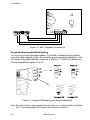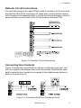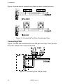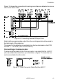
1
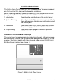
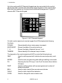
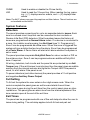
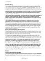
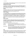
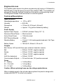
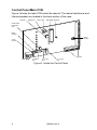
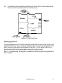
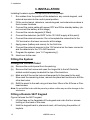
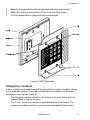
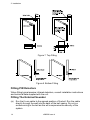
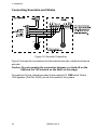
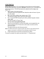
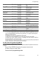
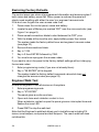
INSTALLATION AND PROGRAMMING GUIDE HARDWIRED CONTROL PANEL Scantronic Leading the way in security Contents 1. INTRODUCTION ......................... 1 Operator Controls and Displays ....... 1 System Features ............................. 3 Detectors .......................................... 3 Full Setting ....................................... 3 Exit Times ......................................... 3 Part Setting ....................................... 4 Entry and Unsetting the System ....... 4 Alarm ................................................ 4 External and Internal Sounders ..... 4 Re-Arm .............................................. 5 First to Alarm Indication and Shock Sensor Reset ............................. 5 Communicator Outputs .................. 6 Keypad Panic Alarm ......................... 6 Chime ............................................... 6 Power Supply ................................... 6 User Control ..................................... 6 Log ................................................... 7 Engineer Access .............................. 7 Technical Description ....................... 7 Specification ..................................... 7 Power Supply ................................... 7 Outputs ............................................. 7 Fuses ................................................. 8 Control Panel Main PCB .................. 8 2. SYSTEM PLANNING .................. 9 Installation Precautions .................... 9 Fitting the System .......................... 12 Fitting the Control Panel ................. 12 Fitting a Remote 9427 Keypad ....... 12 Fitting Door Contacts ...................... 13 Fitting PIR Detectors ...................... 14 Fitting The External Sounder ......... 14 Wiring the Control Panel ................ 15 Cable Entries .................................. 15 Mains Connection .......................... 15 Battery Connection ......................... 15 Connecting a 9427 Remote Keypad15 Keypad Addressing and Backlighting ............................. 16 Detector Circuit Connections ......... 17 Connecting Door Contacts ............. 17 Connecting PIRs ............................ 18 Connecting a Communicator ......... 19 Connecting Sounders and Strobe .. 20 Wiring Example .............................. 21 Initial Start Up ................................ 22 4. PROGRAMMING ...................... 23 Factory Default Programming ........ 23 Changing Default Programming .... 23 Engineer Program Command List . 24 To Re-enter Programming Mode ... 25 Restoring Factory Defaults ............ 26 Engineer Walk Test ........................ 26 Programming Example .................. 27 Locating The Control Panel .............. 9 Locating The External Bell ............... 9 Locating The Deterrent Bell (Dummy)9 Detectors .......................................... 9 Installation Example ...................... 10 Ground Floor .................................. 10 First Floor ....................................... 10 Setting Options ............................... 11 3. INSTALLATION ......................... 12 9448+ Hardwired Control Panel Installation and Programming Guide. © Scantronic Ltd. 1997 Every effort has been made to ensure that the contents of this book are correct. However, neither the authors nor Scantronic accept any liability for loss or damage caused or alleged to be caused directly or indirectly by this book. The contents of this book are subject to change without notice. Printed and published in the U.K. 1. INTRODUCTION The 9448+ Alarm Control Panel is a fully programmable 7 zone control panel with Full and Part Set, designed for domestic installations. Before installing the alarm system, make sure you are familiar with the functions, system plans, and detectors described in this manual. 1. Introduction Describes the main features of the control panel. 2. System Planning Gives typical installation plans and examples. Study these plans before attempting to install and program the control panel. 3. Installation Describes how to fit the control panel and connect the power supply, detectors and alarm devices. 4. Programming Describes how to program the control panel for individual users. Operator Controls and Displays The control panel comprises a single printed circuit board, with microprocessor electronics, mounted in a Polycarbonate casing with a hinged lid. On the outside of the lid is a backlit soft rubber keypad and a column of LED (Light Emitting Diode) displays (see Figure 1). Figure 1. 9448+ Front Panel Layout 496236 Issue 4 1 1. Introduction Up to two optional 9427 Remote Keypads can be connected to the control panel and used in exactly the same way as the keypad on the control panel. Note that the captions on the keys have a different arrangement. Figure 2 shows a 9427 Remote Keypad. Figure 2. 9427 Remote Keypad. On both control panel and remote keypad the LEDs display the following functions: POWER Glows steadily when mains power is present. ENTRY/EXIT Shows the state of the entry/exit zone. 1-6 Shows the state of detector zones 1 to 6. TAMPER Glows steadily if the tamper loop is broken. The keypad on the control panel and 9427 provide the following keys: OMIT Used to set the panel with individual zones temporarily omitted. ENTER Used to enter programming and setting/unsetting commands. PA Pressing the two PA keys (1 and 3) at the same time starts a PA alarm. PART Used to set the system with a preprogrammed number of detectors omitted. BELL Used to start a test of the sounders and strobe. WALK Used to start a test of the detectors. CODE Used to change the user access code. 2 496236 Issue 4 1. Introduction CHIME LOG Used to enable or disable the Chime facility. Used to read the 10-event log. When reading the log, pressing << (1) displays earlier events, and >> (3) displays later events. Note: The 9427 shows zones and key captions not listed above. These functions are not available on the 9448+. System Features Detectors The panel provides connections for up to six separate detector zones. Each zone is a closed circuit loop that can be connected to door contacts or Passive Infra Red (PIR) detectors. Whe the system leaves the factory all zones are programmed as Normal Alarm zones. If no device is connected to a zone, the Installer must program it as Not Used (see "4. Programming"). Zone 5 can be programmed as a Fire zone. When this zone is triggered the system will give a distinctive two-tone fire alarm. Zone 6 can be programmed as a Panic Alarm. A Panic Alarm will start a full alarm whether the system is set or unset. The panel provides a separate Entry/Exit Zone for a door contact or PIR on the entrance door. Zone 3 can be programmed as an additional Entry/Exit zone if required. All wiring, detectors, bell circuits and the panel lid are protected by an Anti Tamper loop. If the anti-tamper loop is broken then the panel gives an audible warning from the internal sounder and lights the Tamper LED if the panel is unset, or a full alarm if the panel is set. To power detectors (and other devices) the panel provides a 12 volt positive and negative Auxiliary Power Output. Full Setting To full set the system the user enters a four digit access code. When the code is complete the panel gives an exit tone and starts the exit timer. If any zone is open during the exit time then the control panel gives an interrupted tone. The panel gives an alarm tone from the internal speakers if the zone remains open at the end of the exit time. Exit Times The panel can be programmed with one of five exit delays to allow the user to leave during setting. The exit delay applies to both full set and part set. 496236 Issue 4 3 1. Introduction Part Setting The Installer can program the panel so that certain zones are omitted if the user sets the system by keying "2 + ENTER + ACCESS CODE". (You cannot program the system to omit Entry/Exit zones.) This facility can be used, for example, to protect a downstairs floor while the family is sleeping upstairs. The part set system may need a separate Entry/Exit Zone from the full set system. In the example, family members will enter the protected area by the stairs rather than by the front door. The Installer can program zone 1 to be an Entry/Exit Zone while the system is part set. Once programmed, opening zone 1 when the system is part set starts the entry timer. Note that zone 1 behaves as an Entry Route when the system is full set. The Installer can also program the system for Silent Part Set. Once programmed, the control panel does not give any tones during the exit time. The Installer can program the alarm response during part set to be either Full (internal and external sounders, and trigger Intruder communications output pin) or Internal Sounder Only (no external sounders, do not trigger Intruder output pin). See "Communication Outputs" overleaf for a description of the communicator output pins. Entry and Unsetting the System Opening the Entry/Exit Zone when the panel is set starts the entry timer, and the panel gives an entry tone. The panel can be programmed with one of five delays to allow the user to get in and unset the panel. If the entry time elapses before the end user enters the access code, the panel starts a fixed 30 second Dual Ply timer and gives an internal alarm. The user must enter a valid access code before the Dual Ply timer runs out or the panel starts a full alarm. The Installer can disable the Dual Ply timer in programming. The panel then gives a full alarm at the end of the entry time. Normally Zone 1 is an Entry Route zone; it is ignored during the entry/exit time. If necessary the Installer can program zone 2 as an additional Entry Route. If the user strays from the Entry Route then the panel starts the Dual Ply timer and gives an internal alarm. If the user does not enter the access code before the Dual Ply timer ends then the panel gives a full alarm. If the Installer disables the Dual Ply timer then the panel starts a full alarm as soon as the user strays from the Entry Route. Alarm External and Internal Sounders The panel provides two separate transistorised outputs to control an External Sounder and Strobe. The external sounder and strobe usually comprises a 4 496236 Issue 4 1. Introduction bell or siren fitted in a tamper proof housing with the strobe warning light fitted to the casing. A control module fitted within the casing contains a rechargeable battery which will continue to ring the bell/siren if the wiring is cut or the casing is tampered with. This type of module is used to power a sounder or bell which will typically draw no more than 450mA. Opening the bell tamper switch or damaging the wiring will cause a Full Alarm to occur. The trigger provided by the panel is negative applied in alarm condition (SAB). The control panel uses an internal loudspeaker to give Entry, Exit and Alarm tones. There is a volume adjuster within the panel which allows you to change the volume of the Entry/Exit tones. An external 16 ohm loudspeaker (for example a Type 9040) can also be connected to the panel. The Installer can program the panel to sound the alarm for one of several set times and then fall silent. Re-Arm The Installer can program the control panel to rearm itself after an alarm. With this option selected, the panel silences the alarm at the end of its programmed time and rearms ready for another activation. If the option is not selected, the internal and external sounders will remain silent until the user enters their access code. The panel can be programmed to rearm up to three times. First to Alarm Indication and Shock Sensor Reset The panel provides a Programmable Output (O/P) which can be used for PIR Set Latch or Shock Sensor Reset. If two or more PIR detectors are fitted to a zone then the panel cannot identify which unit caused an alarm. Connecting O/P to the Latch input of the detectors on the zone overcomes this problem. When O/P is programmed as PIR Set Latch the panel activates the output when the exit time expires, resetting the detectors. When an alarm occurs the panel deactivates the output. This latches the indicator of the unit triggered and inhibits all other units. The first detector to alarm will then have its activity LED glowing, while the others will be dark. This output can also be used for break glass detectors. (Note that the panel also deactivates the output when the system is unset.) Stand-alone shock sensors normally latch when they are triggered. To reset the detectors automatically, connect the negative supply from the detectors to O/P and program O/P as Shock Sensor Reset. At the start of the exit time the panel deactivates the output for six seconds to clear the latched devices. (Refer to the sensor manufacturer's instructions for more details on the reset methods available.) Communicator Outputs The panel provides two output pins which can be used to trigger a Speech or Digital Communicator. One pin is fixed as PA and the other as Intruder. The pins are normally +12V when quiescent, changing to 0V in alarm (positive 496236 Issue 4 5 1. Introduction removal to trigger). After an alarm the pins will return to their quiescent state (+12V) when the user resets the system. Keypad Panic Alarm The Installer can program the panel so that users can start a Panic Alarm by pressing keys 1 and 3 at the same time on any keypad. The Panic Alarm works whether the system is set or unset. When the panel is supplied from the factory this feature is disabled. Chime The internal sounders can give a chime tone when selected detectors are activated while the system is unset. The Installer selects the zones during programming. The user can turn the facility on or off. Power Supply To comply with BS4737, the control panel's mains supply should come from an un-switched, fused spur unit fitted with a 1A fuse. All electrical connections should be carried out by a qualified electrician and must comply with the current IEEE Wiring Regulations: 16 Edition, Appendix 5 - Standard Circuit Arrangement. The control panel must be fitted with a rechargeable stand-by battery so that the system can continue to operate during a mains power failure. User Control The panel provides two independent 4-digit user access codes (defaults 1234 and 0000). The user can change either of these codes at any time, but cannot program the system with these codes. Note that the default second user code (0000) is inactive. The user can set the panel in the following modes: Full Set All the zones function as programmed during installation. Part Set Selected zones are omitted. The Installer must program which zones will be omitted. Set with Omit One or more zones temporarily omitted. The user selects the zones to be omitted during setting. Note that the user cannot omit zone 6 if it is programmed as a Panic Alarm, zone 5 if it is programmed as a Fire zone, or any Entry/Exit zone. Log The panel keeps a record of the last 10 alarm and tamper events. The Installer can read the log in programming mode by using command 90 (see "4. Programming"). The system displays events by lighting the appropriate LEDs on the keypads. To see earlier events press << (1), for later events press >> (3). 6 496236 Issue 4 1. Introduction Engineer Access The Installer gains access to system programming by keying in 0 followed by ENTER and a 4-digit Engineer Access Code (default 7890). The Installer can change the Engineer Access Code at any time while in programming mode. The Engineer Access Code cannot set or unset the system. Technical Description Specification Operating temperature Humidity Dimensions Weight Power Supply System Power Supply Quiescent Panel Power Active Panel Power 9427 Remote Keypad Standby Battery = = = = -10º to +50ºC 80% RH 210mm W, 210mm H, 65mm D Approx 1.1kg (without stand-by battery) = = = = = 230VAC (Ambient Temp. 20 º. C) 50mA nominal 150mA nominal 20mA 12 Volt, 2.1AH rechargeable lead-acid, Gel Type battery = 185mm W, 55mm H, 30 mm D Battery Space Outputs Bell, Strobe, O/P and AUX are open collector transistor outputs. Bell = 500mA, 12VDC. negative applied Strobe = 500mA, 12VDC. negative applied O/P = 100mA, 12VDC. negative applied AUX (for detectors) = 300mA, 12VDC Communicator Outputs = PA and Intruder, 12V positive removed. Fuses F1 - Battery = 1A Slow Blow F2 - 12V AUX = 1A Fast Blow F3 - 21 VAC = 1A Slow Blow Caution: When replacing fuses use the ratings quoted above. When installed as part of an intruder alarm system this panel is designed to comply with BS4737 for a bell only system. 496236 Issue 4 7 Control Panel Main PCB Figure 3 shows the main PCB inside the case lid. The mains transformer and internal speaker are located in the back section of the case. NVM Chip Backlight Link Tamper switch Microcontroller Reset Pins Volume Control for Entry/Exit tones Battery Connector Comms Connector 21VAC Connector Connectors F1 - Battery Fuse F3 - 21 VAC Fuse F2 - 12V Aux Fuse Figure 3. Inside the Control Panel 8 496236 Issue 4 2. System Planning 2. SYSTEM PLANNING Installation Precautions Before installation ensure that all windows and doors are secure and do not need repair. False alarms can occur if doors and windows are insecure. Make sure there will be no pets or movement which will directly affect the performance of any movement detectors. Where possible fit locks to the ground and upper floor windows. By delaying an intruder, the alarm system can be simpler, more effective and less likely to false alarm than a complex system covering all rooms and windows. Locating The Control Panel Install the control panel in a safe, unobtrusive position near a mains supply. Stair cupboards are suitable in most houses. Position the unit so that the user can see the control panel easily, and set and unset the system without difficulty. Make sure the user can reach the final door promptly and hear the exit tone at the required distance. Fit an extension speaker if necessary. Locating The External Bell Fit the unit as high as possible, to reduce the chance of interference by an intruder. Locate the unit in a position where it may easily be seen. Do not locate the bell facing heavy traffic or a railway as this can affect the ability of the bell to be heard at a relatively short distance. The wiring to the unit should enter the bell directly through the wall. Never run surface wiring to an external bell. Locating The Deterrent Bell (Dummy) For additional protection a 'Dummy' bell housing can be fitted to the other sides of the building. The housings are identical in appearance to the real unit but do not contain any equipment. These act as good deterrents from any elevation to show the house is protected. Detectors There are several types of detector available suitable for a simple domestic installation: A Passive Infra Red (PIR) is a movement detector which detects an intruder by infra red body heat compared to the normal room level. A Door contact is a magnetic reed switch used to detect the opening of windows or doors. A Vibration detector is designed to detect a shock attack on a window or door frame. 496236 Issue 4 9 2. System Planning A Panic button is a device used to operate the alarm sounders in the event of threat to the user and will operate irrespective of the panel setting. Installation Example Figure 4 shows a security system fitted to a typical house with two floors. Ground Floor (a) (b) Over two thirds of burglars gain entry through the front or back doors. Figure 4 shows magnetic door contacts fitted to the front and back doors to detect when the doors have been forced. In addition, the system will not set if a door contact is open, prompting the user to check and close doors or windows before setting. The front door is connected to the Entry/Exit Zone (EE), the back door to Zone 2. The downstairs rooms are protected by PIRs (zones 3, 4 and 5). One PIR is fitted in the hallway (zone 1) to start the entry timer and tone when the system is part set. Figure 4. House Ground Floor Plan First Floor (a) 10 The first floor in Figure 5 shows a single PIR (zone 6) fitted on the landing. This ensures that anyone entering the house through a bedroom triggers an alarm when moving onto the landing. Alternatively, zone 6 can be used for a panic button fitted in the main bedroom. 496236 Issue 4 (b) The external bell and strobe is fitted high at the front of the house and a 'Dummy' bell is located to the rear of the house. Figure 5. First Floor Plan Setting Options The occupants should Full Set the system when leaving the house empty, and Part Set the system when sleeping upstairs. Zone 1 should be programmed to start the entry timer when the system is Part Set. This is useful if a child or guest inadvertently strays downstairs when the system is set. See "4. Programming - Example" for details of how to program the system for this example. 496236 Issue 4 11 3. Installation 3. INSTALLATION Installing the alarm system comprises the following steps: 1. Run cables from the position of the detectors, any remote keypad, and external sounders to the control panel position. 2. Fit the control panel, detectors, remote keypad, and external sounders in their chosen locations. 3. Connect the mains cable with power OFF and fit the standby battery (do not connect the battery at this stage). 4. Connect the remote keypads (if fitted). 5. Connect the detectors (but NOT to the 12V AUX supply at this point). 6. Connect the external sounder. Do not complete the connection to the 12V terminal on the lower connector at this stage. 7. Apply power (battery and mains) for the first time. 8. Connect the external sounder to the 12V terminal on the lower connector and the detectors to the 12V AUX terminal. 9. Program the system (see "4. Programming"). 10. Hand over to the user. Fitting the System Fitting the Control Panel (a) (b) (c) (d) Remove the control panel from the packing. Remove the front screw and open the hinged lid to the left. Note the slotted central keyway located at the top of the back box. Mark and drill the centre hole and temporarily fix the panel to the wall. Now mark the remaining holes, remove the panel and continue to drill the other two holes. Refit the panel to the wall using not less than 30mm x No 8 Dome or Panhead screws. Note: Do not drill the holes with the panel in position as this may result in damage to the electronics. Fitting a Remote 9427 Keypad Figure 6 shows the 9427 keypad. 1. Lift the flaps on the faceplate of the keypad and undo the four screws holding on the back of the case. 2. Hold the keypad back in place and mark, drill and plug the position of keyhole. 12 496236 Issue 4 3. Installation 3. 4. 5. Mount the keypad back with a single screw through the keyhole. Mark, drill and plug the position of two more mounting holes. Fix the keypad back in place with two more screws. Figure 6. 9427 Backplate Fitting Door Contacts A door contact comprises a magnetic reed switch housed in a plastic casing and a separate magnet. Two types of switches are suitable for a domestic installation (see Figures 7 and 8): The 'Surface' contact is fitted on the facing of the door frame with the magnet fitted in-line on the door. The 'Flush' contact is inserted in a pre-drilled hole in the frame. The magnet is similarly inserted in the door and aligned with the contact. 496236 Issue 4 13 3. Installation Figure 7. Top Fitting Figure 8. Bottom Fitting Fitting PIR Detectors When fitting typical passive infrared detectors, consult installation instructions and technical data supplied with the unit. Fitting The External Sounder (a) 14 Run the 6 core cable to the agreed position of the bell. Run the cable directly through the wall into the back of the bell casing. Do not run surface wiring to the bell as this will compromise the security of the system. 496236 Issue 4 3. Installation (b) Separate the back plate from the cover. Mount the required module and the bell to the back plate. Fix the strobe to the cover using suitable fixings. Fix back plate to the wall using not less than 40mm x 8 screws. If available fix using 10mm Rawl Bolts. Wiring the Control Panel Cable Entries The back of the control panel case provides a 30mm round cable entry at the left hand side and a trunking knockout at the top left. Mains Connection The panel must be permanently connected to an unswitched spur outlet fitted with a 1 Amp fuse. Connect the mains supply to the control panel using the 3way terminal block located in the panel back. Note that the panel does not have an internal mains fuse. All electrical connections should be carried out by a qualified electrician and must comply with the current IEEE Wiring Regulations: 16 Edition, Appendix 5 - Standard Circuit Arrangement. Figure 9. Mains Connection Caution: Do not apply mains power at this point. Battery Connection The control panel must be fitted with a 2.1AH maximum rechargeable battery. Caution: Do not apply battery power at this point. Connecting a 9427 Remote Keypad Figure 10 shows the connections for a 9427 Keypad. 496236 Issue 4 15 3. Installation Figure 10. 9427 Keypad Connections Keypad Addressing and Backlighting You can fit up to two remote keypads. (The 9448+ software will not handle more than two keypads.) Each one must be given a separate "address". Link LK1 sets the keypad address, as shown in Figure 11. Use LK4 to switch the remote keypad backlights on or off. Figure 11. Keypad Addressing and Keypad Backlight Note:The control panel, when supplied from the factory, is configured with its backlight ON. To turn the backlight OFF clip the link indicated in Figure 3. 16 496236 Issue 4 3. Installation Detector Circuit Connections The right hand edge of the main PCB provides a connector for the six zones and the Entry/Exit Zone, see Figure 12. Each zone (circuit) should have an Anti-Tamper circuit associated with it. Link all the zone anti-tamper circuits in series and then connect them to the A/T terminals on the main PCB. Figure 12. Detector Circuit Connections Connecting Door Contacts Figure 13 shows the connections for one door contact per zone loop. Use four core cable for the tamper and circuit connections. Note that the reed switch inside the door contact is connected to the plated screws (shown in black in Figures 8 and 9). Figure 13. Connecting One Door Contact per Zone 496236 Issue 4 17 3. Installation Figure 14 shows how to connect more than one door contact per zone. Figure 14. Connecting Two Door Contacts per Zone Connecting PIRs Figure 15 shows the connections for one PIR per zone loop. Use 6 core for the power, tamper and circuit connections Figure 15. Connecting One PIR per Zone. 18 496236 Issue 4 3. Installation Figure 16 shows the connections for wiring more than one detector to a zone. Use 8 core alarm cable. Figure 16. Connecting Several PIRs per Zone Note that the programmable output from the control panel should be wired to the latch input of the detectors. The power for the detectors is available from the two terminals on the PCB marked "+ - 12V AUX" (max current 300mA). Connecting a Communicator To wire a communicator to the Com connector, use cable Part No. 485127. (You can obtain this cable from your distributor.) Figure 17 shows the connections available from the cable. Figure 17. Com Connector Cable Part No 485127 496236 Issue 4 19 3. Installation Connecting Sounders and Strobe Figure 18. Sounder Connection Figure 18 shows the connections for the external sounder, strobe and internal sounder. Caution: Do not complete the connection between +ve Hold off on the SAB and the 12V terminal on the 9448+ at this stage. Connections for the internal sounder(s) are marked LS. ONE extra 16ohm 12W speaker (Part No. 9040) can be connected to the system. 20 496236 Issue 4 3. Installation Wiring Example Figure 19 shows an example system wired for two detectors. Note that mains and battery connections are not shown. Figure 19. Wiring Example 496236 Issue 4 21 Initial Start Up Before applying power to the control panel, ensure that any remote keypad and all zone circuits are connected. DO NOT connect the 12V terminal to the external sounder or 12VAUX terminals to the detectors at this stage (see Figure 16). 1. Apply mains to the control panel. The green power LED lights and the internal sounder will sound. Ignore any other lights 2. Key-in the factory default user access code: 1234. The internal sounder stops. Ignore any other lights. 3. Key-in 0 then ENTER followed by the factory default engineer access code: 7890. All LEDs, except for Power, flash. You are now in programming mode. 4. Open the control panel lid, connect the battery, and complete the connections between the 12V terminal on the lower connector and the external sounder. The external sounder should become silent. Note: The SAB module in the external sounder will continue to ring until the hold off supply is connected, or until the bell cover lid tamper switch is closed. 5. Close the panel lid once all the connections are made. Proceed to program the system as described in "4. Programming". 22 496236 Issue 4 4. Programming 4. PROGRAMMING When supplied from the factory the panel is already programmed with a set of default options. These are listed below. Factory Default Programming Feature Zones omitted in part set Chime Zones Not Used Engineer code User code 1 User code 2 Silent Part Set Zone 2 Auto Rearm Bell time Entry time Exit time Zone 6 Prog O/P Zone 1 in Part Set Part set alarm response Zone 3 Zone 5 Dual Ply Keypad 1 & 3 PA default To change use command: none 10 none 11 none 15 7890 20 1234 21 0000 (inactive until changed) 22 No 35 Normal Alarm 36 Never 40 20 minutes 42 20 seconds 43 10 seconds 44 Normal Alarm 50 PIR set latch 51 Normal Alarm 52 Full Alarm 53 Normal Alarm 54 Normal Alarm 55 Enabled 64 Disabled 68 Changing Default Programming To change the factory defaults, the panel must be in programming mode. Then: 1. Key in a two digit programming command followed by "ENTER". (See "Engineer Program Command List".) On commands 35 to 68 a LED will glow to show you the current option used in the command. If the LED is OFF the option is "0". 2. Key in the correct digit for the option you want, and then press ENTER. 496236 Issue 4 23 4. Programming The panel beeps twice to show that it has accepted the command. All the LEDs flash, and the panel is ready for the next command. The panel gives a single error tone if you enter an incorrect command. Re-enter the correct command. 3. Key in "99 ENTER" to leave programming mode when you have finished. You will then be in user mode. Engineer Program Command List To change: Zones omitted in Part Set* Chime Zones Not Used Engineer Code User Code 1 User Code 2 Silent Part set Zone 2 Entry Route Auto Re-Arm Bell Time Entry time Exit time 24 Key-in: followed by: 10 ENTER zone n..n ENTER Notes LEDs ON for zones omitted (see note 1) 11 ENTER zone n..n ENTER LEDs ON for chime (EE zone = zone 7) 15 ENTER zone n..n ENTER LEDs OFF for zone not used (see note 2) 20 ENTER new code ENTER 4 digits 21 ENTER new code ENTER 4 digits (see note 3) 22 ENTER new code ENTER 4 digits (see notes 3 & 4) 35 ENTER 0 ENTER Audible 1 ENTER Silent 36 ENTER 0 ENTER Normal Alarm 1 ENTER Entry Route 40 ENTER 1 ENTER Never rearm 2 ENTER Rearm once 3 ENTER Rearm twice 4 ENTER Rearm three times 42 ENTER 1 ENTER 90 seconds 2 ENTER 3 minutes 3 ENTER 10 minutes 4 ENTER 20 minutes 43 ENTER 1 ENTER 10 seconds 2 ENTER 20 seconds 3 ENTER 30 seconds 4 ENTER 45 seconds 5 ENTER 1 minute 44 ENTER 1 ENTER 10 seconds 2 ENTER 20 seconds 3 ENTER 30 seconds 4 ENTER 45 seconds 5 ENTER 1 minute 496236 Issue 4 4. Programming Zone 6 50 ENTER 0 ENTER 1 ENTER Prog O/P 51 ENTER 0 ENTER 1 ENTER Zone 1 in Part Set 52 ENTER 0 ENTER 1 ENTER Part Set Alarm 53 ENTER 0 ENTER Response 1 ENTER Zone 3 54 ENTER 0 ENTER 1 ENTER Zone 5 55 ENTER 0 ENTER 1 ENTER 30-second 64 ENTER 0 ENTER Dual Ply 1 ENTER Keypad 1 & 3 PA 68 ENTER 0 ENTER 1 ENTER View Log 90 ENTER Walk Test Load Defaults Normal Alarm PA PIR set latch Shock reset Normal Alarm Entry/Exit Full Alarm Internal sounder Normal Alarm Entry/Exit Normal Alarm Fire Enabled Disabled Disabled Enabled Press << to see earlier events, >> for later events. 97 ENTER Trigger detectors. Press OMIT to exit test. 98 ENTER Does not change access Leave Program 99 ENTER codes (See note 5.) Notes: 1. n..n = the numbers of the zones. Key the zone number to toggle the zones on or off. Pressing ENTER stores the zones selected. You cannot omit Entry/Exit zone(s) in Full or Part set. 2. Program any zones not connected as "Not used". 3. The end user may change the user codes (see separate user guide). 4. Default user code 2 "0000" is inactive. Changing user code 2 back to "0000" at any time makes the code inactive again. 5. If the internal sounder activates when you use this command then check the lid tamper, bell tamper, and the global zone anti tamper. To Re-enter Programming Mode You can re-enter programming mode at any time when the panel is not set or in alarm: Key-in 0 then ENTER followed by the engineer access code. All LEDs, except for Power, flash. You are now in programming mode. 496236 Issue 4 25 Restoring Factory Defaults The control panel can retain all programmed information and access codes if both mains and battery power fail. When power is restored the panel will simply need resetting with either the user's or engineer's access code. If the end user forgets the user access code then: 1. Power down the control panel, mains and battery. 2. Locate the pair of Molex pins marked 'RST' near the microcontroller (see Figure 3 on page 8). 3. Place a small screwdriver blade to short between the 'RST' pins. 4. With the blade still across the pins, apply battery power then mains. The system loads the factory default user and engineer's access codes (see page 23). 5 Remove the screwdriver blade. 6. Key in 1234. 7 Key in 0 then ENTER followed by 7890. 6 You must now reprogram the access codes. If you want to return the panel to the factory default settings without changing the access codes: 1. Enter programming mode (if you are not already there). 2. Key in "98 ENTER" at the keypad. The system loads the factory default command values but does not changes the access codes (see page 23). Engineer Walk Test Allows the engineer to test all devices on the system. 1. Enter programming mode. 2. Key in "97 ENTER" The panel gives a continuous tone. 3. Open and close each detector contact in turn. When a detector contact is open the panel gives an interrupted tone and flashes the zone LED. 4. Press OMIT to stop the walk test. Note that the Engineer's walk test allows you to test all zones including PA zones, zone tampers, and panel and bell tampers. The user's walk test does not allow this. 26 496236 Issue 4 Programming Example To program the installation example given in Section 2 some changes need to be made to the factory default settings. For the example we will assume that the: Entry time must be 30 seconds Exit time must be 45 seconds. Entry Exit zone and back door should chime. System should rearm three times. Key in: Result 1. 0 + ENTER + 7890 The panel enters programming mode and all LEDs (except Power) flash in unison. 2. 10 + ENTER + 6 + ENTER Zone 6 is by passed during Part Set. 3. 11 + ENTER + 72 + ENTER Entry exit zone and zone 2 are chime zones. 4. 40 + ENTER + 4 + ENTER Rearm three times. 5. 43 + ENTER + 3 + ENTER Entry time 30 seconds. 6. 44 + ENTER + 4 + ENTER Exit time 45 seconds. 7. 52 + ENTER + 1 + ENTER Zone 1 is Entry/Exit Zone in Part Set. 8. 99 + ENTER Leave programming mode. If you wish to make zone 6 a PA zone, then you could add the step: 7a. 50 + ENTER + 1 + ENTER Zone 6 is a PA zone. 496236 Issue 4 27 Manufactured in the UK by Scantronic Ltd. Product Support (UK) - Tel - (0891) 616343 between 09:00 and 17:30, Monday to Friday. (CALLS CHARGED AT 50P PER MINUTE.) PRODUCT SUPPORT FAX NO. (01594) 544136. Part No. 496236 Issue 4