1
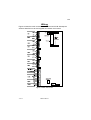
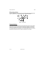
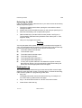
9800
Installation and User Guide
Compatible Equipment
9825
9827
9040
9056
9076-01/02
960
9066
Remote Keypad
Remote Keypad
Internal loudspeaker (16 Ohm). 2 max, fit at least one.
Plug-on Digital Communicator
Signalling Relay Interface
Speech/Digital Communicator
Self-Activating Bell (SAB) Module
496334 Issue 1
1 of 14
9800
Introduction
The 9800 Alarm Control Panel comprises a control unit in a shielded case,
and up to four separate keypads.
The control unit provides:
°
Connections for up to eight Closed Circuit zones.
°
Connections for four outputs (external sounder, strobe, and two fully
programmable outputs).
°
Connections for up to four 9825 Keypads.
°
Pins for fitting a plug-on communication device. Any device that
complies with the Scantronic plug-on footprint can be fitted.
°
Internal sounder loudspeaker output with electronically generated
Chime, Alarm and Fire tones.
The programming interface is arranged as a set of two-digit numbered
commands.
The system can provide for up to 4 separate users. User facilities include:
°
Three different security levels (full set and two part sets) which can be
programmed by the installer.
°
User programmable Duress code.
°
Keyswitch setting/unsetting.
Technical Specifications
General
Operating temperature
Humidity
Dimensions
Weight
Standby Battery
= -10 °C to + 40 °C.
= Up to 80% non-condensing.
= h x w x d 300 x 300 x 75 mm.
= 4.85 Kg (excl battery).
= 12 Volt, 6.0Ah rechargeable lead-acid, Gel
Type battery.
Power Supply
The total current available from the control unit is as follows:
System output current
= 800mA (Ambient Temp. 20 °C).
Control unit pcb
= 60mA quiescent.
= 500mA active (when driving standard
external bell).
Each 9825 Remote Keypad
= 20mA quiescent.
= 60mA active.
2 of 14
496334 Issue 1
9800
9825 Keypad Addressing
Standard 9066 SAB Module
Plug-on 9056 Communicator
= 40mA.
= 40mA.
Keypad Wiring
Recommended maximum distances for the remote keypads from the control
unit, using standard alarm cable is 100 metres for the star configuration.
Outputs
OP1, OP2, Bell, Strobe
= 500mA. Transistorised outputs capable of
driving a relay.
9825 Keypad Addressing
Before connecting the keypad(s) to the system, the engineer must set the
address of each keypad. Each keypad in a system must have a different
address number to ensure that the control unit can correctly identify them.
To set the address:
1. Ensure the system is powered down.
2. Open the keypad and identify the four position DIP switch on the keypad
pcb, see Figure 1 below. Note that each switch is numbered 1 to 4. The
numbers correspond to the keypad address.
Figure 1. Keypad Address Switch
3.
Select one switch and move it to the ON position (up). Make sure all the
other switches are OFF (down). The keypad now has the address given
by the switch that is ON.
Adjusting Keypad Sounder Volume
You can alter the volume of the keypad sounder by adjusting the potentiometer located next to the sounder. See Figure 1. When first installing the
keypad set the potentiometer midway using a small screwdriver.
496334 Issue 1
3 of 14
9800
Wiring
Figure 2 shows the main connector on the control unit PCB. Subsequent
sections describe how to wire keypads and closed circuit zones.
Figure 2. Main Connector
4 of 14
496334 Issue 1
9800
Wiring Keypads
Wiring Keypads
All keypads must be connected to Keypad terminals on the control unit PCB
or "daisy chained" to other keypads. Figure 3 shows the connections for each
keypad using the 9285 as an example:
Figure 3. Wiring the 9285 Keypad
Note: The output for the lock release interface must be a transistorised type. A
recommended type is RS Components 349-254. A SEPARATE 12 Volt DC
supply is required. Contact rating is 10 A.
Caution: Do not connect other devices (for example SAB, speakers and so on) in the
same cable as the remote keypad wiring.
496334 Issue 1
5 of 14
Wiring Keyswitches
9800
Wiring Keyswitches
Connect a keyswitch to the I/P and 0V terminals of the nearest keypad (see
Figure 4). Make sure you use a two position, unbiased keyswitch.
Figure 4. Keyswitch
Communications
The control unit can be fitted with communicators that conform to the standard Scantronic plug-on communicator footprint (for example, the 9056 and
9058 Plug-on Digital Communicators, a 960 Speech/Digital Communicator,
or a Plug-on Red Care Transmitter). For communicators that do not conform
the 9076-01 and 9076-02 can be used as interfaces to the system.
6 of 14
496334 Issue 1
9800
Programming
Initial Power Up
When all wiring is complete, power up the system for the first time as follows:
1. Ensure that the keypad(s) and detectors are securely fitted and their
tamper switches closed.
2. Connect the battery and then close the case.
3. Switch on the mains power. Ignore any tones from the internal and
keypad sounders.
4. Go to a keypad and key in 1234.
5. Key in 0 followed by 7890 (the default Engineer’s code).
The keypad gives an intermittent tone.
6. Open the end station lid. (If the lid is already open, close and open the
tamper switch.)
The displays shows “E” (engineer).
You are now in programming mode.
Programming Commands
When delivered from the factory the control unit already has default program
settings. To change the default programming you must be in programming
mode. Then:
1. Key in the appropriate command number.
The display shows the current value of the command.
2.
Key in digits to select the value you require.
The display shows a code giving the new value.
3. Press Clear to store the new value of the command.
If at any time you change your mind, repeat step 1 to 3. The table on the
following pages shows the commands and their options. ( A y next to a
command value shows that it is the factory default.)
The factory default access codes are:
Engineer Code
7890
Access Code User 1
1234
Access Code 2 to 4
AAAA (inactive)
Access Code 3
BBBB (inactive)
Access Code 4
CCCC (inactive)
Duress Code
OMIT, OMIT, OMIT, OMIT (inactive)
Note: The factory default Access Codes 02 to 04 and the Duress Code must be
changed by USER 1 to a four digit number to activate them.
496334 Issue 1
7 of 14
Engineer Program Commands
9800
Engineer Program Commands
To change:
Zone n
Notes
Default
n = zone number 01 to 08
x = Zone type, one of:
0 = nu (not used)
y
1 = PA (panic alarm)
2 = Fr (fire zone)
3 = Al (normal alarm)
4 = 24 (24 hour zone)
5 = FE (final exit)
6 = ER (entry route)
y = Zone attributes, any of:
7 = ch (chime)
8 = St (soak test)
9 = 2A (double knock)
B = b (armed in part set B)
C = c (armed in part set C)
OMIT = OA (omit allow)
Example: Zone 3 is a Normal Alarm, active in Part Set B and C, that is Omit Allowed. Type in: 03 Zone Number
3 Normal Alarm
B Active in Part Set B
C Active in Part Set C
OMIT Omit Allow
CLEAR to store the value of the command.
Output 1
11 x y
x = Output Type, one of:
0 = Bell follow
1 = Exit/entry follow
2 = Set latch type 1
Y
3 = Set latch type 2
4 = Shock sensor reset
5 = Walk test
6 = Entry system
7 = 24 hour alarm
y = Output state, one of:
8 = positive applied
Y
9 = positive removed
Output 2
12 x y
(as for command 11)
49
Engineer Code
20 nnnn Engineer code
7890
Bell Output Type
21 0
SAB, negative applied in alarm
Y
1
SCB, negative removed in alarm
Loudspeaker Chime
22 1
Chime through loudspeaker & kypds
Y
0
Chime through keypads only
RedCare reset †
23 0
Disabled
Y
1
Enabled
8 of 14
Key-in:
0n x y
496334 Issue 1
9800
To change:
Duress mode
Internal Sounder
Sounder Delay on Entry
PA Response
Night Line Fault Response
Day Line Fault Response
System Reset
PA Reset
First circuit lockout
Entry Abort
Day tamper comms †
and Engineer on Site
Keypad Input
Exit Mode
Auto Re-Arm
Bell Delay
Engineer Program Commands
Key-in:
24 0
1
25 0
1
26 0
1
30 0
1
31 0
1
32 0
1
33 0
1
34 0
1
35 0
1
36 0
1
37 0
1
38 0
1
2
39 0
1
2
40 0
1
2
3
4
41 0
1
2
3
4
5
6
7
Notes
Default
Audible
Silent
Y
Follows external bell
Y
Continuous
Normal
Delay always
Y
Audible
Y
Silent
Full alarm
No alarm
Y
Audible
Y
Silent
User reset
Y
Engineer reset
User reset
Y
Engineer reset
Lock out
Y
Re-arm
Disabled
Y
Enabled (90 seconds abort time)
Disable (local audibles only)
Y
Enabled, communicator channel 5
Exit terminate
Y
Keyswitch
Lockset
Timed or terminate set
Y
Final door set
Lock set
Never
Once
Y
Twice
Three times
Always
No delay
Y
1.5 minutes
3 minutes
5 minutes
10 minutes
15 minutes
20 minutes
Infinite delay
496334 Issue 1
9 of 14
Engineer Program Commands
9800
To change:
Bell Duration
Key-in:
Notes
Default
42 1
1.5 minutes
2
3 minutes
3
5 minutes
4
10 minutes
5
15 minutes
6
20 minutes
Y
7
nil
Entry Time
43 1
10 Seconds
Y
2
20 seconds
3
30 seconds
4
45 seconds
5
60 seconds
6
120 seconds
Exit Time
44 0
Continuous (exit terminate only)
1
10 Seconds
Y
2
20 seconds
3
30 seconds
4
45 seconds
5
60 seconds
6
120 seconds
CSID Code
50 n...n Seed code for remote reset
Available from Jan 1993 on all models.
Area B final exit response
60 0
Final exit
Y
1
Normal alarm
Area B Entry route
61 0
Entry route
Y
1
Start entry timer
Area B Exit mode
62 0
As full set
1
Quick set (10s)
Y
2
Instant set
3
Deferred set
Area B Alarm response
63 0
Keypad sounders only
1
Internal and keypad sounders
Y
2
All sounders, no comms
3
Full alarm (comms and sounders)
Area C final exit
70
see 60
Area C Entry route
71
see 61
Area C Exit mode
72
see 62
Area C Alarm response
73
see 63
Event log
90 1
View earlier events
3
View later events
Test External Bells
91 Bell output operates
Clear Bell test ends
Test Strobe
92 Strobe output operates
Clear Strobe test ends
Test Internal sounder
93 Internal sounder operates
Clear Internal sounder test ends
10 of 14
496334 Issue 1
9800
Leaving Programming Mode
To change:
Test keypad sounder
Test output 1
Test output 2
Walk Test
Load defaults
Leave programming
Key-in:
Notes
94 Keypad sounder operates
Clear Keypad sounder test ends
95 Programmable output 1 operates
Clear Output 1 test ends
96 Programmable output 2 operates
Clear Output 2 test ends
97 Zone LED and sounder operate when
circuit open
Clear End walk test
98 Load defaults
99
Default
Leaving Programming Mode
When all programming has been completed:
1. Key-in ‘99’ at the keypad.
The display clears and the Day LED is ON.
The system is now in user mode.
Note: If there is a fault on the system , for example an open tamper circuit, the
display shows this and will not return to Day mode. Press Y (Clear) and rectify
the faults.
Engineer Reset
To perform an Engineer Reset:
1. Check that the display is showing the alarm condition. (Note: if the
display shows “rr”, Press Clear twice.)
2. Key in 0 followed by the Engineer’s code (default 7890), followed by 99.
The display goes blank and the Day LED glows.
Re-Entering Programming Mode
“Initial Power Up” describes how to enter programming mode for the first time
in a new installation. If you wish to enter programming mode at any other
time:
1. Make sure the system is unset.
2. Press 0, then key in the Engineer’s code (default 7890).
The keypad gives an intermittent tone.
3.
Open the end station lid.
The display shows “E” (for ‘engineer’) and the intermittent tone stops.
You are now in programming mode.
496334 Issue 1
11 of 14
Refreshing the NVM
9800
Refreshing the NVM
If the user and/or engineer codes are lost, or you want to revert to the factory
default programming, then:
1. First remove mains power before opening the case and then disconnecting the battery.
2. Identify and remove the NVM chip (IC4) on the main pcb (see Figure 1).
3. Reconnect the battery, then re-apply mains power.
4. Refit the NVM chip (note the locator marker position, see Figure 1).
The end station loads the factory default access codes (User 1: 1234,
engineer: 7890).
5.
Carry on to re-program the system.
Testing
You may test parts of the system by entering commands at the keypad. To
carry out a test make sure the system is in programming mode and then key
in one of the following commands. Press Clear to end each test:
91
To test the external sounder/bell.
92
To test strobe output.
93
To test the internal sounder output.
94
To test the keypad sounder.
95
To test programmable output No. 1.
96
To test programmable output No. 2.
97
To carry out a system walk test. This allows the engineer to test all
alarm devices. When a circuit is opened, the internal sounder(s) will
emit a tone and the appropriate circuit LED lights.
Reading the Log
The control unit keeps a 60 event log of recent events. Each event is represented by a two digit code, shown on the next page. To review the event log,
make sure the system is in programming mode, then:
1. Key in 90.
The display shows the most recent event in the log, for example "c7".
For a list of the log codes see the next page.
2.
3.
Key in 1 to show earlier events or 3 to see more recent events.
Press Clear to leave the log.
12 of 14
496334 Issue 1
9800
Event Log Displays
The table below shows all the messages that can appear in the event log.
The left hand column shows the codes that appear on a keypad display.
Event Log Displays
Keypad
AA
Ab
Ac
AE
AP
bF
c1 to c8
cc
cF
E1 to E8
EA
EF
Lb
Lf
Lt
o1 to o8
PF
r1 to r4
rP
rr
rt
S1 to S8
Sr
t1 to t8
tr
u1 to u9
Meaning
Arm area A (full set)
Arm area B (part set)
Arm area C (part set)
Installer access
Auxiliary power failure
Battery fault
Zone violation
Communication successful
Communications failure
Entry via zone circuit
Entry alarm
Exit fault
Low battery
Telephone line failure
End station lid tamper
Zone omitted
Mains power failure
Remote keypad back tamper
Remote keypad missing
Installer reset required
Remote keypad excess key presses tamper
Zone soak Test
System reset (total power failure)
Zone tamper violation
Tamper return fault
Access user (u5 = Duress, u9 = keyswitch)
496334 Issue 1
13 of 14
9800
User Commands
Set/Unset System
User code + A
Part Set
User code + B or C
Omit zone (1-8)
User code + A, B or C + OMIT + Zone number
Omit 24 hour zone
User code + OMIT + Zone number
Reinstate omitted
24 hour zone
User code + OMIT + CLEAR
Change User code
User code + 4 + old code + new code + CLEAR
Read Log
User code + 5 +
1 to see earlier events or
3 to see later events +
CLEAR + CLEAR
Chime On/Off
User code + 7 + CLEAR
Bell Test
User code + 8
+ CLEAR to end test
Walk Test
User code + 9
+ CLEAR to end test
Note: Duress code default is OMIT OMIT OMIT OMIT and is inactive until changed.
14 of 14
496334 Issue 1