1
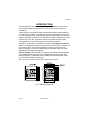
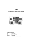
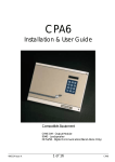
601/602
Installation and User Guide
Compatible Equipment
625
9040
660
Remote Keypad
Internal Sounder
Speech Communicator
496322 Issue 1
1 of 12
601/602
INTRODUCTION
The 601/602 Alarm Control Panel is a fully programmable six zone Alarm
Control Panel designed specifically for domestic and small commercial
installations.
A basic system comprises an Alarm Panel that houses the system electronics, power supply, battery, and speech communicator (if fitted). On the 601 a
numeric keypad and row of Light Emitting Diodes (LEDS) allow the user and
installer to operate the system. The 602 has no keypad or displays except for
a Power LED. The user controls the system from a 625 remote keypad.
The 601/602 can work with all types of intruder alarm detectors.
In addition, the 601/602 control panels can take the 660 Speech Communicator: a small digital recorder that can be fitted within the panel. The 660 can
be programmed to call up to four telephone numbers in the event of an
alarm, and deliver up to four recorded speech messages (refer to the 660
Installation and Programming Guide).
Remote Keypads. The 601/602 can support up to two 625 remote keypads.
The keypads provide the same keys, displays and sounders as the main
panel (see Figure 1). Note that you can disable the Personal Attack signal
from the keypad during programming.
Note: The 602 is supplied complete with one 625 remote keypad.
Fig 1. 625 Remote Keypad
2 of 12
496322 Issue 1
601/602
Technical Specification
Zones
Display
Keypads
Keyswitch
Expansion
Compliance
Log
Panel Siren
Extn Sounder
Battery
12 volt power
Aux DC Power
Dimensions
Weight
Communicator
Input
Outputs
6 Fully programmable closed loop plus
global anti-tamper.
LED (on 601).
601 On-board plus two 625 Remote keypads.
602 two remote keypads (one supplied).
Full and part set keyswitch option.
None.
Security Standards: BS4737 Pt. 1: (Audibles
only).
EMC Standards: Products are tested to EN
50081-1 and EN 50082-1, and are CE
marked accordingly.
15 events.
601 - Yes (80dB at 1m), 602 - not fitted.
1 x 9040 16 Ohm loudspeaker/sounder.
1.9 (2.1)Ah Lead acid gel type rechargeable.
Panel quiescent = 70mA.
Keypad quiescent = 40mA.
230mA max at 12 V quiescent.
h x w x d = 212 x 212 x 68 mm.
1.2 Kg.
PA + Burg + Open/Close outputs for 660
Speech Communicator.
Line fault.
Bell + Strobe (Negative applied (SAB)) giving
a total of 500mA at 12V in alarm state.
Transistorised OP1: programmable output
for PIR Set Latch, Shock Sensor Reset,
Internal alarm giving 150mA max. Armed
and Ready LED outputs for use with keyswitch set.
496322 Issue 1
3 of 12
601/602
Wiring Remote Keypads
Figure 2. Connecting Remote Keypads
Notes: Wire the second keypad, if fitted, in parallel to the first. Connect the cable
either at the first keypad (daisy chain) or at the panel (star). The maximum
cable length is 100m.
Cut the address link in the second keypad to change its address.
If fitting an Exit Terminate button connect a Normally Open button to the
terminals marked 0V and IP on the keypad.
Connecting Keyswitches
Figure 3. Keyswitch Connections
4 of 12
496322 Issue 1
601/602
Fitting a Speech Communicator
Note: Disconnect the speech communicator wiring harness from the main pcb if you
are NOT fitting a communicator.
Figure 4. Speech Communicator Connections
Wire the communicator harness to the 660 as shown in the following table:
601 Function
Colour 660
Pin 1 PA output +ve removed in alarm.
Red
ST2
Pin 2 Line mon. input, 12V +ve applied for Line Fault. Blue
LF
Pin 3 Burglar output +ve removed in alarm.
Yellow ST3
Pin 4 Open/close output +ve removed in alarm.
Black
ST4
Pin 5 12V Supply.
Brown 12V
Pin 6 0V Supply.
Orange 0V
Programming
Initial Power Up
Before applying power to the panel make sure that:
•
All used circuits are connected.
•
The bell trigger is NOT connected to the external sounder.
•
The battery or speech communicator (if fitted) is NOT connected.
•
The global anti tamper circuit is closed and the tamper return (TR) is
linked to 0V.
Note: The panel will not enter programming mode if the global anti tamper is open
circuit, or if the negative tamper return is not present.
1.
2.
Close the 601 (or 602) lid or defeat the lid tamper.
Apply mains power to the 601/602.
The Power LED comes on.
3.
Key in the default user code (1234) if there is an alarm. Ignore any
LEDs that are lit at this stage.
496322 Issue 1
5 of 12
Programming
4.
5.
6.
7.
601/602
For a 601:
Key in 0 + ENTER + the engineer code (default 7890).
The panel bleeps once per second.
Open panel lid or release the panel tamper.
The panel bleeps twice and all the LEDs flash.
You are now in Programming Mode.
For a 602 with 625 keypad:
Key in 0 + ENTER + the engineer code (default 7890).
The keypad bleeps once per second.
Open 602 end station lid or release the tamper.
The 602 bleeps twice if a 9040 sounder is fitted. (Keypad LEDs do not
flash.)
You are now in programming mode.
Connect the battery and make any final wired connections (for example
bell trigger to the external sounder, or communicator harness to main
pcb).
Remember to remove any link between 0V and TR if you are fitting a
SAB.
Programming Commands
To change the factory default program, use the commands listed in this
section as follows:
1. Enter the command number.
2. Enter one or more digits to give the new program.
3. Press ENTER.
The panel will give a double bleep to show that it has accepted the
command. If you enter the command incorrectly the panel gives a single
tone.
Default Settings
When delivered from the factory, the panel is programmed as follows:
Zone 1, Entry/Exit, Chime, active in Part Set.
01 489
Zone 2, Entry Route, active in Part Set, Omit allowed.
02 39 OMIT
Zone 3, Normal Alarm, active in Part Set, Omit allowed. 03 19 OMIT
Zone 4, Normal Alarm, active in Part Set, Omit allowed. 04 19 OMIT
Zone 5, Normal Alarm, Omit allowed.
05 1 OMIT
Zone 6, Personal Attack.
06 5
User 1 code
1234
6 of 12
496322 Issue 1
601/602
Engineer Program Commands
User 2 - 8 code
Duress code
0001 to 0007 * (inactive)
OMIT OMIT OMIT OMIT
(inactive)
* The default code for user two is “0001”, for user 3 it is “0002” and so on up
to user 8, which is “0007”. Refer to the 601 User Guide for instructions on
changing the user codes.
Engineer Program Commands
To change
Zones 1-6
Example:
Select one zone type
from 0 to 7.
Choose which attributes
you require from 8, 9
and OMIT.
The press ENTER.
Programmable Output 1
Key in: Then:
01-06 0 ENTER
1 ENTER
2 ENTER
3 ENTER
4 ENTER
5 ENTER
6 ENTER
7 ENTER
In addition:
8 ENTER
9 ENTER
OMIT ENTER
12
18 ENTER
Example:
To select Shock Sensor
Reset key in 12 28 and
then press ENTER.
Engineer Access
Key Switch Operation
20
21
PA
30
System Reset
31
2-Ply Entry Timer
32
Keypad PA
33
Set/Part Set Display
34
Exit Mode
35
Notes
Not used
Normal Alarm
24 Hour Alarm
Entry Route
Entry/Exit
PA
Fire Alarm
Technical Alarm
Default
Chime
Active in Part Set
Omit Allowed
PIR Set Latch (+ve applied
y
when active)
28 ENTER Shock Sensor Reset (+ve removed
when active)
49 ENTER Strobe (-ve switched)
59 ENTER Internal Alarm (+ve applied when
active)
Any 4 digit code
7890
0 ENTER Momentary
y
1 ENTER Latched
0 ENTER Audible Alarm
y
1 ENTER Silent Alarm
0 ENTER Customer Reset
y
1 ENTER Engineer Reset
0 ENTER Disabled
y
1 ENTER Enabled
0 ENTER Disabled
1 ENTER Enabled
y
0 ENTER LEDs ON when set and part set
1 ENTER LEDs OFF when set and part set y
0 ENTER Timed or Terminated
y
1 ENTER Final Door Set
496322 Issue 1
7 of 12
Engineer Program Commands
To change
Rearm
601/602
Key in:
40
External sounder delay
41
Ext. sounder duration
42
Entry Time
Exit Time
43
44
Part Set Entry/Exit
60
Part Set Entry Route Zone
Response
Part Set Exit Mode
61
Part Set Alarm Response
63
8 of 12
62
Then:
0 ENTER
1 ENTER
2 ENTER
3 ENTER
4 ENTER
0 ENTER
1 ENTER
2 ENTER
3 ENTER
4 ENTER
5 ENTER
6 ENTER
0 ENTER
1 ENTER
2 ENTER
3 ENTER
4 ENTER
5 ENTER
6 ENTER
1 ENTER
2 ENTER
3 ENTER
4 ENTER
5 ENTER
6 ENTER
0 ENTER
1 ENTER
2 ENTER
3 ENTER
4 ENTER
5 ENTER
6 ENTER
0 ENTER
1 ENTER
0 ENTER
1 ENTER
0 ENTER
1 ENTER
2 ENTER
0 ENTER
1 ENTER
Notes
Never
Once
Twice
Three times
Always
Nil
1.5 minutes
3 minutes
5 minutes
10 minutes
15 minutes
20 minutes
Nil
1.5 minutes
3 minutes
5 minutes
10 minutes
15 minutes
20 minutes
1seconds
10 seconds
15 seconds
20 seconds
30 seconds
60 seconds
Continuous
1 seconds
10 seconds
15 seconds
20 seconds
30 seconds
60 seconds
Starts Entry Timer
Instant Alarm
As Entry Route
Start Entry Timer
As Full Set
Silent Set
Instant Set
Local (No comms)
Full
496322 Issue 1
Default
y
y
y
y
y
y
y
y
y
601/602
Restoring Factory Default Settings
Restoring Factory Default Settings (Command 98)
If you want to restore all the programming to the original factory defaults,
then:
1. Key in 98 + ENTER.
The panel erases all programming the user or previous engineers have
entered, and restores the original factory defaults.
Leaving Programming Mode (Command 99)
1.
2.
Close panel lid.
Key in 99 ENTER.
The panel bleeps twice and the Power LED glow steadily. The panel is
now in user mode.
To Re-enter Programming Mode
1.
Key in 0 + ENTER + (engineer access code)
The panel starts bleeping once per second.
2.
Open the panel lid.
The panel bleeps twice and on the 601 all the LEDs flash. The panel is
now in programming mode.
Restoring Default Engineer and User Codes
If you want to remove any programmed Engineer and User codes (perhaps
to reuse the panel with another user) then:
1. Remove Mains supply.
2. Open 601/602 lid and remove Battery supply.
Note: Leave the lid open and make sure the Lid Tamper switch does not close, or
this procedure will not work.
3.
4.
5.
6.
On the 601: hold down OMIT and 9 and reconnect battery supply.
On the 602: short together the two RST pins on the main pcb with a
small screwdriver and reconnect battery supply. Remove the screwdriver after three seconds.
Close lid and key in 1234.
Follow normal programming procedure as described in “Initial Power
Up”.
496322 Issue 1
9 of 12
601/602
Testing
Once the panel is installed, connected and programmed, there are several
programming commands that can be used to test it while in Programming
Mode. These are listed below (Press ENTER to stop any test.):
To Test
Engineer Log
External Sounder
Strobe
Internal Sounder
Output 1
Walk Test
Key in:
90
91
92
93
95
97
Then:
4 see earlier events.
5 to see more recent events.
ENTER to quit log. (15 events max.)
ENTER to stop test.
ENTER to stop test.
ENTER to stop test.
ENTER to stop test.
ENTER to stop test.
Fault Finding
Power LED flashes continuously
•
•
Mains supply has failed, panel operating from battery only.
Check mains connection and fuse.
Sab will not stop ringing
•
•
•
•
SAB not receiving power.
Check 12V supply present.
Check tamper switch on external sounder.
Ensure cover on external sounder is secure.
Alarm activated, tamper light flashing rapidly after user code entered
•
•
•
Check negative tamper return present.
Check global anti tamper is closed circuit.
Check lid tamper is properly closed.
Alarm activated, tamper light pulses every two seconds
•
Check for telephone line failure.
After entering engineer code the sounder bleeps every second, but when lid
tamper opened system will not enter into programming mode
•
•
•
10 of 12
Check that the global anti-tamper terminals are closed circuit.
Check the negative tamper return is present.
If lid tamper is already open, close and open it again.
496322 Issue 1
601/602
User Commands
Full Set/Unset
User code
Part Set
2 + ENTER + User code
Omit zone
User code + OMIT + zone number + (repeat OMIT
and zone number for other zones to be omitted)
Chime On/Off
7 + ENTER + User code
Panic Alarm
1 + 3 together. Panel does not give any indication
of alarm
Read Log
5 + Enter + User code
press 4 to read earlier events
press 6 to read later events
Change User code
4 + ENTER + User code
+ current User code
+ new User code
Walk Test
9 + ENTER + User code
press ENTER to end test
Bell Test
8 + ENTER + User code
496322 Issue 1
11 of 12
12 of 12
496322 Issue 1