1
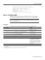
About This Guide
This chapter discusses the objectives, audience, organization, and conventions of the Dial Solutions
Quick Configuration Guide.
Cisco documentation and additional literature are available on the Documentation CD-ROM. The
CD is updated and shipped monthly so it might be more current than printed documentation. To
order the Documentation CD, contact your local sales representative or call Customer Service. The
CD is available both as a single CD and as an annual subscription. To order the CD, contact your
local sales representative or call Cisco Customer Service. You can also access Cisco technical
documentation via Cisco Connection Online on the World Wide Web URL http://www.cisco.com.
Document Objectives
This quick configuration guide describes the tasks you perform to solve common business problems
with dial networking technologies. It presents the most common dial access tasks in a format that
enables you to configure your access server quickly for the most common tasks. It does not describe
every feature, but describes those tasks that you most likely need to do to configure your access
server.
This guide begins with a case study followed by configuration scenarios. It also references detailed
configuration options described in the Cisco IOS configuration guides and command references so
that you can refer to these other documents for additional information.
Prerequisites
This guide assumes you understand the task for which your access server was purchased.
The configuration options indicated in this quick configuration guide are the recommended methods
for performing the specified tasks. Although they are typically the easiest or the most straightforward
method, they are not the only methods of configuring these tasks. If you know of another
configuration method not presented in this guide, you can use it.
About This Guide ix
Audience
Audience
This guide is intended primarily for the following audiences:
•
System administrators who are familiar with the fundamentals of router-based internetworking
and who are responsible for installing and configuring internetworking equipment, but who
might not be familiar with the specifics of Cisco products or the routing protocols supported by
Cisco products.
•
•
Customers who support dial-in users, but who have little experience with router-based networks.
Customers who know one networking protocol (such as Novell IPX) and one LAN protocol (such
as Ethernet), but have no additional networking background or experience.
Document Organization
This guide has two parts:
•
Part 1, “Dial Case Study”—This part describes how to build a network that provides a dial-up
environment using one Cisco AS5300. The access server supports remote users and remote
LANs connecting with modems and ISDN routers. Only IP networking and basic security are
described.This case study gives you a basic foundation from which you can scale to support
larger dial implementations.
— Chapter 1, “Dial Case Study Overview”
— Chapter 2, “Cisco AS5300 Configuration”
— Chapter 3, “Cisco 1604 Configuration”
— Chapter 4, “Cisco 766 Configuration”
•
Part 2, “Expanded Dial-Up Configurations”—This part provides comprehensive sample
configurations for mixed protocol scenarios (IP, IPX, and AppleTalk). It also describes how to
route over modem lines and set up security. Refer to the Dial Solutions Configuration Guide for
more information.
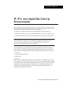
— Chapter 5, “IP, IPX, and AppleTalk Dial-Up Environments”
— Chapter 6, “Routing across Modem Lines”
— Chapter 7, “Security Configuration”
Document Conventions
This document uses the following conventions:
Convention
Description
^ or Ctrl
Represents the Control key. For example, when you read ^D or Ctrl-D, you should
hold down the Control key while you press the D key. Keys are indicated in capital
letters but are not case sensitive.
string
A string is defined as a nonquoted set of characters. For example, when setting an
SNMP community string to public, do not use quotation marks around the string;
otherwise, the string will include the quotation marks.
x Dial Solutions Quick Configuration Guide
Document Conventions
Examples use the following conventions:
Convention
Description
screen
Shows an example of information displayed on the screen.
boldface screen
Shows an example of information that you must enter.
<
Nonprinting characters, such as passwords, appear in angled brackets.
>
!
[
Exclamation points at the beginning of a line indicate a comment line. They are also
displayed by the Cisco IOS software for certain processes.
]
Default responses to system prompts appear in square brackets.
The following conventions are used to attract the reader’s attention:
Caution Means reader be careful. In this situation, you might do something that could result in equipment
damage or loss of data.
Note Means reader take note. Notes contain helpful suggestions or references to materials not
contained in this manual.
Timesaver Means the described action saves time. You can save time by performing the action described in
12
9
3
the paragraph.
6
About This Guide xi
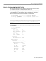
Command Syntax Conventions
Command Syntax Conventions
Command descriptions use the following conventions:
Convention
Description
boldface
Indicates commands and keywords that are entered literally as shown.
italics
Indicates arguments for which you supply values; in contexts that do not allow italics,
arguments are enclosed in angle brackets (< >).
[x]
Keywords or arguments that appear within square brackets are optional.
{x | y | z}
A choice of required keywords (represented by x, y, and z) appears in braces separated
by vertical bars. You must select one.
[x {y | z}]
Braces and vertical bars within square brackets indicate a required choice within an
optional element. You do not need to select one. If you do, you have some required
choices.
Where to Go for More Information
Refer to the following list of resources:
•
•
•
•
Cisco Connection Online
Technical Assistance Center
European Technical Assistance Center
Documentation Set
Cisco Connection Online
Cisco Connection Online (CCO) is Cisco Systems’ primary, real-time support channel.
Maintenance customers and partners can self-register on CCO to obtain additional information and
services.
Available 24 hours a day, 7 days a week, CCO provides a wealth of standard and value-added
services to Cisco’s customers and business partners. CCO services include product information,
product documentation, software updates, release notes, technical tips, the Bug Navigator,
configuration notes, brochures, descriptions of service offerings, and download access to public and
authorized files.
CCO serves a wide variety of users through two interfaces that are updated and enhanced
simultaneously: a character-based version and a multimedia version that resides on the World Wide
Web (WWW). The character-based CCO supports Zmodem, Kermit, Xmodem, FTP, and Internet
e-mail, and it is excellent for quick access to information over lower bandwidths. The WWW version
of CCO provides richly formatted documents with photographs, figures, graphics, and video, as well
as hyperlinks to related information.
You can access CCO in the following ways:
•
•
•
•
WWW: http://www.cisco.com
WWW: http://www-europe.cisco.com
WWW: http://www-china.cisco.com
Telnet: cco.cisco.com
xii Dial Solutions Quick Configuration Guide
Where to Go for More Information
•
Modem: From North America, 408 526-8070; from Europe, 33 1 64 46 40 82. Use the
following terminal settings: VT100 emulation; databits: 8; parity: none; stop bits: 1; and
connection rates up to 28.8 kbps.
For a copy of CCO’s Frequently Asked Questions (FAQ), contact [email protected]. For
additional information, contact [email protected].
Technical Assistance Center
If you are a network administrator and need personal technical assistance with a Cisco product that
is under warranty or covered by a maintenance contract, contact Cisco’s Technical Assistance Center
(TAC) at 800 553-2447 or 408 526-7209, or [email protected]. Emergency technical assistance
(for network-down or severe network problems) is available 24 hours a day, 7 days a week.
For popular configuration tips and hints gathered from Cisco’s Technical Assistance Center (TAC),
go to the Hot Tips home page at the following URL. This URL is subject to change without notice.
http://www.cisco.com/warp/public/701/
If you choose to telephone the TAC for help, have the following information ready:
•
•
•
•
Chassis serial number
Maintenance contract number
Software version level and hardware configuration (enter the show version command to display
this information)
Running software configuration. To display this information for Release 11.0 or later, enter the
show running config command. For Release 11.0 or earlier, enter the write terminal command.
European Technical Assistance Center
Cisco and its European Service Partners coordinate all customer service in Europe, including
hardware and software telephone technical support, onsite service, and module exchange and repair.
For more information, contact the European TAC.
European TAC numbers and e-mail address are as follows:
•
•
•
Phone: 32 2 778 42 42
Fax: 32 2 778 43 00
E-mail: [email protected]
About This Guide xiii
Where to Go for More Information
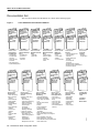
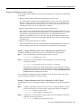
Documentation Set
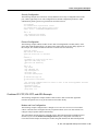
The Cisco IOS software documentation set is shown in the following figure:
Cisco IOS Software Documentation Modules
Module FC
Configuration
Guide
Module P1C
Configuration
Guide
Module P2C
Configuration
Guide
Module P3C
Configuration
Guide
Module FR
Command
Reference
Module P1R
Command
Reference
Module P2R
Command
Reference
Module P3R
Command
Reference
Module FC/FR:
Module P1C/P1R:
Configuration
Network Protocols,
Fundamentals
Part 1
• Configuration
• IP Addressing
Fundamentals
• IP Services
Overview
• IP Routing
• Cisco IOS User
Protocols
Interfaces
• File Management
• System Management
Module DC
Configuration
Guide
Module DR
Command
Reference
Module DC/DR:
Dial Solutions
• Dial-In Port Setup
• Dial-In Terminal
Services
• Dial-on-Demand
Routing (DDR)
• Dial Backup
• Dial-Out Modem
Pooling
• Large-Scale Dial
Solutions
• Cost-Control
Solutions
• ISDN
• X.25 over ISDN
• VPDN
• Dial Business
Solutions
and Examples
Module P2C/P2R:
Network Protocols,
Part 2
• AppleTalk
• Novell IPX
Module WC
Configuration
Guide
Module WR
Command
Reference
Module P3C/P3R:
Network Protocols,
Part 3
• Apollo Domain
• Banyan VINES
• DECnet
• ISO CLNS
• XNS
Module WC/WR:
Wide-Area
Networking
• ATM
• Frame Relay
• SMDS
• X.25 and LAPB
Module XC
Configuration
Guide
Module BC
Configuration
Guide
Module VC
Configuration
Guide
Module XR
Command
Reference
Module BR
Command
Reference
Module VR
Command
Reference
Module XC/XR:
Cisco IOS Switching
Services
• Switching Paths for IP
Networks
- Fast Switching
- Autonomous Switching
- NetFlow Switching
- Optimum Switching
- Cisco Express
Forwarding
- Tag Switching
- Multilayer Switching
• Virtual LAN (VLAN)
Switching and Routing
- Inter-Switch Link
Protocol Encapsulation
- IEEE 802.10
Encapsulation
- LAN Emulation
- Multiprotocol over ATM
Module VC/VR:
Module BC/BR:
Voice, Video, and
Bridging and IBM
Home Applications
Networking
• Voice over IP
• Transparent Bridging
• Voice over Frame
• Source-Route Bridging
Relay
• Token Ring Inter-Switch
• Voice over ATM
Link
• Voice over HDLC
• Remote Source-Route
• Video Support
Bridging
• Universal Broadband
• DLSw+
Features
• STUN and BSTUN
• LLC2 and SDLC
• IBM Network Media
Translation
• DSPU and SNA Service Point
• SNA Frame Relay Access Support
• APPN
• Cisco Database Connection
• NCIA Client/Server Topologies
• Cisco Mainframe Channel Connection
• Airline Product Set
xiv Dial Solutions Quick Configuration Guide
Module SC
Configuration
Guide
Module SR
Command
Reference
Module IC
Configuration
Guide
Module IR
Command
Reference
Module SC/SR:
Module IC/IR:
Security
Cisco IOS
• AAA Security Services
Interface
• Security Server
• Interface
Protocols
Configuration
• Traffic Filtering and
Firewalls
• IP Security and
Encryption
• Passwords and Privileges
• Neighbor Router Authentication
• IP Security Options
Module QC
Configuration
Guide
Configuration
Guide Master
Index
Module QR
Command
Reference
Command
Reference
Master Index
Module QC/QR:
Quality of Service
Solutions
• Classification
• Scheduling
• Packet Drop
• Traffic Shaping
• ATM QoS
• SNA QoS
• Line Protocols
Configuration
Guide Master
Index
Command
Reference
Master Index
14796
Figure 1
Using Cisco IOS Software
This chapter provides helpful tips for understanding and configuring Cisco IOS software using the
command-line interface (CLI).
•
•
•
•
Getting Help
Understanding Command Modes
Using the No and Default Forms of Commands
Saving Configuration Changes
For an overview of Cisco IOS software configuration, refer to the Configuration Fundamentals
Configuration Guide.
For information on the conventions used in the Cisco IOS documentation set, refer to the “About this
Guide” chapter at the beginning of this book.
Getting Help
Entering a question mark (?) at the system prompt displays a list of commands available for each
command mode. You can also get a list of any command’s associated keywords and arguments with
the context-sensitive help feature.
To get help specific to a command mode, a command, a keyword, or an argument, use one of the
following commands:
Command
Purpose
help
Obtain a brief description of the help system in any command
mode.
abbreviated-command-entry?
Obtain a list of commands that begin with a particular character
string. (No space between command and question mark.)
abbreviated-command-entry<Tab>
Complete a partial command name.
?
List all commands available for a particular command mode.
command ?
List a command’s associated keywords. (Space between command
and question mark.)
command keyword ?
List a keyword’s associated arguments. (Space between the
keyword and question mark.)
xv
Getting Help
Finding Command Options
This section provides an example of how to find and display the syntax for a command. The syntax
can consist of optional or required keywords. To display keywords for a command, enter a question
mark (?) at the configuration prompt, or after entering part of a command followed by a space.
The Cisco IOS software displays a list of keywords available along with a brief description of the
keywords. For example, if you were in global configuration mode, typed the command arap, and
wanted to see all the keywords for that command, you would type arap ?.
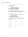
The following table shows you how to find the command options for the following two commands:
•
•
Table 1
controller t1 1
cas-group 1 timeslots 1-24 type e&m-fgb dtmf
How to Find Command Options
Command
Comment
Router> enable
Password: <password>
Router#
Enter the enable command and password to
access privileged EXEC commands.
Router# config terminal
Enter configuration commands, one per line. End with CNTL/Z.
Router(config)#
Enter global configuration mode.
You have entered privileged EXEC mode
when the prompt changes to Router#.
You have entered global configuration
mode when the prompt changes to
Router(config)#.
Router(config)# controller t1 ?
<0-3> Controller unit number
Router(config)# controller t1 1
Router(config-controller)#
Enter controller configuration mode by
specifying the T1 controller that you want
to configure using the controller t1 global
configuration command.
Enter a ? to display what you must enter
next on the command line. In this example,
you must enter a controller unit number
from 0 to 3.
You have entered controller configuration
mode when the prompt changes to
Router(config-controller)#.
Router(config-controller)# ?
Controller configuration commands:
cablelength
Specify the cable length for a DS1 link
cas-group
Configure the specified timeslots for CAS (Channel
Associate Signals)
channel-group Specify the timeslots to channel-group mapping for an
interface
clock
Specify the clock source for a DS1 link
default
Set a command to its defaults
description
Controller specific description
ds0
ds0 commands
exit
Exit from controller configuration mode
fdl
Specify the FDL standard for a DS1 data link
framing
Specify the type of Framing on a DS1 link
help
Description of the interactive help system
linecode
Specify the line encoding method for a DS1 link
loopback
Put the entire T1 line into loopback
no
Negate a command or set its defaults
pri-group
Configure the specified timeslots for PRI
shutdown
Shut down a DS1 link (send Blue Alarm)
Router(config-controller)#
xvi Dial Solutions Quick Configuration Guide
Enter a ? to display a list of all the
controller configuration commands
available for the T1 controller.
Getting Help
Table 1
How to Find Command Options (Continued)
Command
Comment
Router(config-controller)# cas-group ?
<0-23>
Channel number
Router(config-controller)# cas-group
Enter the command that you want to
configure for the controller. In this
example, the cas-group command is used.
Enter a ? to display what you must enter
next on the command line. In this example,
you must enter a channel number from 0
to 23.
Because a <cr> is not displayed, it indicates
that you must enter more keywords to
complete the command.
Router(config-controller)# cas-group 1 ?
timeslots
List of timeslots in the cas-group
Router(config-controller)# cas-group 1
After you enter the channel number, enter a
? to display what you must enter next on
the command line. In this example, you
must enter the timeslots keyword.
Because a <cr> is not displayed, it indicates
that you must enter more keywords to
complete the command.
Router(config-controller)# cas-group 1 timeslots ?
<1-24>
List of timeslots which comprise the cas-group
Router(config-controller)# cas-group 1 timeslots
After you enter the timeslots keyword,
enter a ? to display what you must enter
next on the command line. In this example,
you must enter a list of timeslots from 1 to
24.
You can specify timeslot ranges (for
example, 1-24), individual timeslots
separated by commas (for example 1, 3, 5),
or a combination of the two (for example
1-3, 8, 17-24). The 16th time slot is not
specified in the command line, because it is
reserved for transmitting the channel
signaling.
Because a <cr> is not displayed, it indicates
that you must enter more keywords to
complete the command.
Router(config-controller)# cas-group 1 timeslots 1-24 ?
service
Specify the type of service
type
Specify the type of signaling
Router(config-controller)# cas-group 1 timeslots 1-24
After you enter the timeslot ranges, enter a
? to display what you must enter next on
the command line. In this example, you
must enter the service or type keyword.
Because a <cr> is not displayed, it indicates
that you must enter more keywords to
complete the command.
Router(config-controller)# cas-group 1 timeslots 1-24 type ?
e&m-fgb
E & M Type II FGB
e&m-fgd
E & M Type IIFGD
e&m-immediate-start E & M Immediate Start
fxs-ground-start
FXS Ground Start
fxs-loop-start
FXS Loop Start
sas-ground-start
SAS Ground Start
sas-loop-start
SAS Loop Start
Router(config-controller)# cas-group 1 timeslots 1-24 type
In this example, the type keyword is
entered. After you enter the type keyword,
enter a ? to display what you must enter
next on the command line. In this example,
you must enter one of the signaling types.
Because a <cr> is not displayed, it indicates
that you must enter more keywords to
complete the command.
xvii
Getting Help
Table 1
How to Find Command Options (Continued)
Command
Comment
Router(config-controller)# cas-group 1 timeslots 1-24 type e&m-fgb ?
dtmf
DTMF tone signaling
mf
MF tone signaling
service
Specify the type of service
<cr>
Router(config-controller)# cas-group 1 timeslots 1-24 type e&m-fgb
In this example, the e&m-fgb keyword is
entered. After you enter the e&m-fgb
keyword, enter a ? to display what you
must enter next on the command line. In
this example, you can enter the dtmf, mf,
or service keyword to indicate the type of
channel-associated signaling available for
the e&m-fgb signaling type.
Because a <cr> is displayed, it indicates
that you can enter more keywords or press
<cr> to complete the command.
Router(config-controller)# cas-group 1 timeslots 1-24 type e&m-fgb dtmf ?
dnis
DNIS addr info provisioned
service
Specify the type of service
<cr>
Router(config-controller)# cas-group 1 timeslots 1-24 type e&m-fgb dtmf
In this example, the dtmf keyword is
entered. After you enter the dtmf keyword,
enter a ? to display what you must enter
next on the command line. In this example,
you can enter the dnis or service keyword
to indicate the options available for dtmf
tone signaling.
Because a <cr> is displayed, it indicates
that you can enter more keywords or press
<cr> to complete the command.
Router(config-controller)# cas-group 1 timeslots 1-24 type e&m-fgb dtmf
Router(config-controller)#
xviii Dial Solutions Quick Configuration Guide
In this example, enter a <cr> to complete
the command.
Understanding Command Modes
Understanding Command Modes
The Cisco IOS user interface is divided into many different modes. The commands available to you
at any given time depend on which mode you are currently in. Entering a question mark (?) at the
system prompt allows you to obtain a list of commands available for each command mode.
When you start a session on the router, you begin in user mode, often called EXEC mode. Only a
limited subset of the commands are available in EXEC mode. In order to have access to all
commands, you must enter privileged EXEC mode. Normally, you must enter a password to enter
privileged EXEC mode. From privileged mode, you can enter any EXEC command or enter global
configuration mode. Most of the EXEC commands are one-time commands, such as show
commands, which show the current status of something, and clear commands, which clear counters
or interfaces. The EXEC commands are not saved across reboots of the router.
The configuration modes allow you to make changes to the running configuration. If you later save
the configuration, these commands are stored across router reboots. In order to get to the various
configuration modes, you must start at global configuration mode. From global configuration mode,
you can enter interface configuration mode, subinterface configuration mode, and a variety of
protocol-specific modes.
ROM monitor mode is a separate mode used when the router cannot boot properly. If your router or
access server does not find a valid system image when it is booting, or if its configuration file is
corrupted at startup, the system might enter read-only memory (ROM) monitor mode.
Summary of Command Modes
The following table summarizes some of the main command modes of the Cisco IOS software.
Table 2
Summary of Main Command Modes
Command
Mode
Access Method
Prompt
Exit Method
User EXEC
Log in.
Router>
Use the logout command.
Privileged
EXEC
From user EXEC mode, use Router#
the enable EXEC command.
Global
configuration
From privileged EXEC
mode, use the configure
terminal privileged EXEC
command.
Router(config)#
From global configuration
mode, enter by specifying an
interface with an interface
command.
Router(config-if)#
From interface configuration
mode, specify a subinterface
with an interface command.
Router(config-subif)#
Interface
configuration
Subinterface
configuration
To exit back to user EXEC mode, use the disable command.
To enter global configuration mode, use the configure
terminal privileged EXEC command.
To exit to privileged EXEC mode, use the exit or end
command or press Ctrl-Z.
To enter interface configuration mode, enter an interface
configuration command.
To exit to global configuration mode, use the exit command.
To exit to privileged EXEC mode, use the exit command or
press Ctrl-Z.
To enter subinterface configuration mode, specify a
subinterface with the interface command.
To exit to global configuration mode, use the exit command.
To enter privileged EXEC mode, use the end command or
press Ctrl-Z.
xix
Using the No and Default Forms of Commands
Table 2
Command
Mode
ROM monitor
Summary of Main Command Modes (Continued)
Access Method
Prompt
Exit Method
From privileged EXEC
mode, use the reload EXEC
command. Press the Break
key during the first 60
seconds while the system is
booting.
>
To exit to user EXEC mode, type continue.
For more information regarding command modes, refer to the “Using the Command Line Interface”
chapter of the Configuration Fundamentals Configuration Guide.
Using the No and Default Forms of Commands
Almost every configuration command also has a no form. In general, use the no form to disable a
function. Use the command without the keyword no to reenable a disabled function or to enable a
function that is disabled by default. For example, IP routing is enabled by default. To disable IP
routing, specify the no ip routing command and specify ip routing to reenable it. The Cisco IOS
software command references provide the complete syntax for the configuration commands and
describes what the no form of a command does.
Configuration commands can also have a default form. The default form of a command returns the
command setting to its default. Most commands are disabled by default, so the default form is the
same as the no form. However, some commands are enabled by default and have variables set to
certain default values. In these cases, the default command enables the command and sets variables
to their default values. The Cisco IOS software command references describe what the default form
of a command does if the command is not the same as the no form.
Saving Configuration Changes
Enter the copy system:running-config nvram:startup-config command to save your configuration
changes to your startup configuration so that they will not be lost if there is a system reload or power
outage. For example:
Router# copy system:running-config nvram:startup-config
Building configuration...
It might take a minute or two to save the configuration. After the configuration has been saved, the
following output appears:
[OK]
Router#
On most platforms, this step saves the configuration to nonvolatile random-access memory
(NVRAM). On the Class A Flash file system platforms, this step saves the configuration to the
location specified by the CONFIG_FILE environment variable. The CONFIG_FILE variable
defaults to NVRAM.
xx Dial Solutions Quick Configuration Guide
C H A P TER
1
Dial Case Study Overview
This case study builds a dial-up network environment using one Cisco AS5300. The access server
supports remote users and remote LANs connecting with modems and ISDN routers. The remote
routers in this case study are a Cisco 1604 and Cisco 766. Only IP and basic security are used.
This exercise gives you a basic foundation from which you can scale to support larger dial
implementations.
The following sections are provided:
•
•
•
•
“Scenario Description” on page 1
“Design Architecture” on page 4
“Overview of Tasks” on page 9
“Related Documents and Web Tools” on page 10
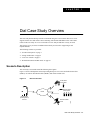
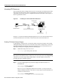
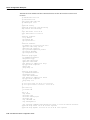
Scenario Description
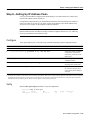
The case study is structured around the following three figures.
Figure 1-1 shows a headquarters network providing dial-up services to one small office/home office
(SOHO), one remote office/branch office (ROBO), and remote modem users.
Figure 1-1
Business Scenario
Small office/
home office
Headquarters
providing dial-up
services
Remote modem
users
15581
PSTN
Remote office/
branch office
Dial Case Study Overview 1-1
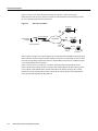
Scenario Description
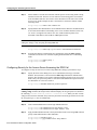
Figure 1-2 shows some of the physical elements present at layer 1 of the Open System
Interconnection (OSI) reference model. The public switched telephone network (PSTN) provides
the core interconnecting fabric between devices.
Figure 1-2
OSI Layer 1 Elements
Cisco 766
LAN
BRI
line
Four T1 PRI lines
Headquarters
network
PSTN/ISDN
BRI
line
Cisco 1604
LAN
Cisco AS5300
point-of-presence
POTS
line
Modem
Remote PC
15986
RS-232
In this scenario, a single Cisco AS5300 supports 96 concurrent modem and ISDN connections using
four T1 PRI lines and 96 integrated modems. Modem connections are established via the Cisco IOS
lines and corresponding asynchronous interfaces. Digital ISDN connections are established via the
Cisco IOS channelized serial interfaces.
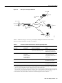
Figure 1-3 shows the layer 2 and layer 3 elements. The links going across the PSTN use the
Point-to-Point Protocol (PPP). In this case study scenario PPP negotiates the link control protocol
(LCP), CHAP or PAP authentication, and IP Control Protocol (IPCP) to bring up IP over PPP.
IPCP is the network control protocol (NCP) used in this case study. IPCP is the mechanism that
opens the links and negotiates the IP parameters.
1-2
Dial Solutions Quick Configuration Guide
Scenario Description
Figure 1-3
OSI Layer 2 and Layer 3 Elements
10.1.3.1/24
Ethernet
10.1.254.3/24
PPP
10.1.254.4/24
PPP
10.1.1.10/24
PSTN/ISDN
Ethernet
10.1.254.1/24
PPP
10.1.4.1/24
Remote PC
PPP
15582
Headquarters
IP network
Table 1-1 summarizes the types of services provided by the headquarters POP to the remote nodes
and sites. For more information, see Table 1-2 on page 4.
Table 1-1
Scenarios and Site Characteristics Provided by Headquarters
Scenario
Remote
Hardware1
Services Required
2
Notes
Remote node modem
Modem
Asynchronous shell (async shell)
Asynchronous PPP (async PPP)
Dial in only4. Remote
devices are assigned an IP
address from a central pool.
Remote node ISDN
ISDN routers using
port address
translation (PAT)3,
PC-based ISDN
terminal adapters
Synchronous PPP (sync PPP)
Dial in only4. PAT enabled.
Connecting devices are
assigned an IP address from a
central pool.
Remote office LAN
Cisco 1604
Synchronous PPP
Dial in and dial out4. Distinct
IP subnet. PAT not used.
Small office LAN
Cisco 766
Synchronous PPP
Dial in and dial out4. Distinct
IP subnet. PAT not used.
1. This is the typical hardware required at the remote site.
2. Cisco IOS shell terminal services can be used for low-level troubleshooting on asynchronous connectivity. The shell is the service
you use to access the command line interface. The shell provides you with a terminal screen.
3. PAT = Port address translation. Easy IP is an implementation of PAT. PAT vastly simplifies IP addressing design when supporting
remote sites. This case study does not describe how to configure PAT. For more information, see the Dial Solutions Configuration
Guide. PAT is mentioned in this table to show you how the technology is positioned in the remote access paradigm.
4. Unless otherwise stated, the terms “dial-in” and “dial-out” are from the perspective of the Cisco AS5300.
Dial Case Study Overview 1-3
Design Architecture
Design Architecture
The following sections provide the framework for this case study:
•
•
•
•
Service Definitions
Layer 3 IP Design
IP Subnet Rationale
Call Processing Components
Service Definitions
In this case study, the Cisco AS5300 offers three basic services: async shell, async PPP,
and sync PPP. See Table 1-2.
These services are based on real needs as requested by the remote sites. To access these services,
remote devices connect to the Cisco AS5300 via the PSTN.
Table 1-2
Services Provided by Headquarters
Security
Method Used
Service Term
Purpose
Physical Data Path1
Async shell
Provides access to Cisco IOS terminal
services (no PPP) to do the following:2
Client modems, POTS3,
Cisco IOS integrated
modems, lines, and
asynchronous interfaces
Login
Client modems, POTS3,
Cisco IOS integrated
modems, lines, and
asynchronous interfaces
PPP
(CHAP, PAP, or
login)
End-to-end ISDN using
B channels over a digital
synchronous path, calls
use interface serial
channels (for example,
S0:1, S0:2, and so forth)
PPP
(CHAP or PAP)
• Change passwords
• Access menus
• Troubleshoot modem connections using a
simple environment
• Access other network resources via telnet
Async PPP
• Provides IP (and multi-protocol)
connectivity for remote node modem users
• Supports any Internet application available
using IP such as e-mail, web browsing,
FTP, and Telnet.
Sync PPP
• Provides IP (and multi-protocol)
connectivity for BRI or PRI attached
remote sites.
• Supports any Internet application available
using IP such as e-mail, web browsing,
FTP, and Telnet4.
1. This is the equipment and interface path used to deliver calls into the Cisco AS5300. See Figure 1-5.
2. Terminal services provided by the Cisco AS5300’s integrated modems are terminated on TTY and VTY lines. The Cisco IOS shell
is called the EXEC, which you can reach via a modem. The Cisco IOS shell is secured using “login” security. Authentication
security associated with the EXEC is referred to as login. Sites offering terminal services can use menus to improve the user
friendliness of the environment. For tips on how to create menus, see the Configuration Fundamentals Configuration Guide.
3. POTS = Plain old telephone service.
4. Terminal services via a shell are not available to synchronous link users (for example, ISDN routers and terminal adapters via a BRI
channel). Only an asynchronous shell is available.
1-4
Dial Solutions Quick Configuration Guide
Layer 3 IP Design
Layer 3 IP Design
This case study uses PPP to transport IP packets across the PSTN and into the end-user devices
(remote LAN or remote node). IPCP is the specific service enabled over the PPP links. To deliver
this service, the case study uses address space from 10.1.0.0 /16. See the following figures and tables
for the IP subnetting plan.
Figure 1-4
IP Subnetting Diagram
10.1.1.0/24
Hq-access
10.1.3.0/24
Tahoe LAN
Dialer cloud
(PSTN/ISDN)
10.1.254.0/24
10.1.4.0/24
Austin LAN
16023
10.1.2.0/24
NAS loopback 0
Table 1-3
IP Subnetting Plan
Subnet Name
Assigned Subnet
Location
10.1.1.0 /24
Hq-access Ethernet
10.1.2.0 /24
Loopback interface
inside the Cisco AS5300
Dialer cloud
10.1.254.0 /24
Public switched
telephone network
Tahoe LAN
10.1.3.0 /24
Tahoe Ethernet
Austin LAN
10.1.4.0 /24
Austin Ethernet
...
...
...
...
...
...
Hq-access
NAS loopback 0
2
1
1. NAS = network access server. The loopback subnet supports the remote node devices.
2. These dots mean that you can add additional subnets and remote LANs to this solution.
This case study gives you a basic foundation from which you can scale to support
larger dial implementations.
Dial Case Study Overview 1-5
Design Architecture
Using the subnetting plan and topologies shown in the previous tables and figures, a router naming
and addressing plan is created in Table 1-4. Notice that the IP addresses are derived directly from the
subnet plan.
Table 1-4
Router IP Addressing Plan
WAN
IP Address
Ethernet
IP Address
hq-sanjose
10.1.254.1
255.255.255.0
10.1.1.10
255.255.255.0
soho-tahoe
10.1.254.3
255.255.255.0
10.1.3.1
255.255.255.0
robo-austin
10.1.254.4
255.255.255.0
10.1.4.1
255.255.255.0
...2
...
...
...
...
...
Router Name1
1. Using the subnetting plan and topologies shown in the previous tables and
figures, a router naming and addressing plan is created in are now assigned
host names.
2. These dots mean that you can add additional subnets and remote LANs to
this solution. This case study gives you a basic foundation from which you
can scale to support larger dial implementations.
IP Subnet Rationale
This section describes each IP subnet and its design criteria. IP route summarization occurs at the
gateway that connects the NAS to the IP backbone. IP range 10.1.0.0/16 is propagated to the
backbone.
Hq-access Subnet
IP subnet 10.1.1.0/24 is assigned to the Ethernet connected to the Cisco AS5300. If additional access
servers and POP management devices are needed, they are assigned to this IP subnet. Using one
subnet for the entire headquarters dial access POP simplifies network design.
NAS Loopback 0 Subnet
IP subnet 10.1.2.0/24 is assigned to the loopback interface on the Cisco AS5300. This is the subnet
used to host the remote node IP addresses. The access server has an IP pool range of 10.1.2.2 through
10.1.2.97.
Remote nodes dialing in request addresses from the Cisco AS5300’s local IP address pool.
This IP pool behaves like an address server handing out IP addresses to remote nodes during IPCP
negotiation (a component of PPP).
1-6
Dial Solutions Quick Configuration Guide
Call Processing Components
Dialer Cloud Subnet
IP subnet 10.1.254.0/24 is assigned to the PSTN/ISDN. The static IP addresses are described in
Table 1-4. See the column “WAN IP Address.” The PSTN/ISDN becomes a “dialer cloud” from the
Cisco IOS perspective. Dialer interfaces are used to connect to this dialer cloud. BRI and PRI
interfaces are also dialer interfaces and use the same dial-on-demand routing (DDR) mechanisms to
open and close circuit-switched connections.
A key design decision in this case study is to number the dialer cloud subnet. (That is, IP
unnumbered is not used on these interfaces.) Numbering the dialer cloud ports to match the remote
LAN supported by the same remote device is part of our design strategy to simplify administration.
For example, remote subnet 10.1.3.0/24 is connected to the same remote site as dialer cloud node
10.1.254.3. IP node 10.1.254.4 supports IP subnet 10.1.4.0/24.
On the Cisco AS5300, all the individual serial channel interfaces are grouped together under one
master dialer interface. As the individual remote sites connect, their configurations must coordinate
with the configuration of the master dialer interface.
Tahoe and Austin LAN Subnets
IP subnet 10.1.3.0/24 is assigned to the Ethernet connected to the Cisco 766 (soho-tahoe). IP subnet
10.1.4.0/24 is assigned to the Cisco 1604 (robo-austin) Ethernet. Each site that supports a distinct IP
subnet must be assigned its own distinct IP subnet address space. Routers with LANs behind them
must have their own distinct IP subnets when not using PAT.
These remote LAN routers point to the central site as the default route. The hq-sanjose NAS is
configured with static routes to the remote IP subnets.
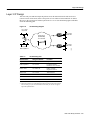
Call Processing Components
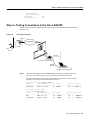
Figure 1-5 illustrates the connectivity path as calls come into the Cisco AS5300. The contents inside
the dotted square box are the internal components of the Cisco AS5300. Both analog modem and
digital calls enter the Cisco AS5300 via the E1/T1 controllers. Incoming modem calls are connected
with the integrated modems and routed to the asynchronous interfaces. Incoming sync PPP calls are
connected to the individual serial channels (for example, S0:1 and S0:2).
As shown in Figure 1-5, one PPP/modem user consumes resources from one channel, one integrated
modem, one line, and one asynchronous interface. An ISDN B-channel user connects directly via a
channel of the T1 and a serial B-channel. The group-async and dialer interfaces are used to control
the interfaces’ behavior and configuration of async and serial channels.
Dial Case Study Overview 1-7
Design Architecture
Figure 1-5
Call Processing Components
Cisco IOS terrain inside
the Cisco AS5300
Headquarters
intranet/internet
Interface dialer
controlling the
D channels
Interface
group-async
Fast Ethernet
interface
Routing and
switching engine
Cloning
Cloning
Interface
async
Lines
Interface serial
channels S0:1, S0:2…
(B channels)
Modems
TDM bus
Controllers T1/E1
Cisco AS5300
BRI line
Cisco 1604
15042
PRI lines
PSTN/ISDN
Remote
PC
BRI line
Cisco 766
POTS line
Modem
= ISDN B channel
= Modem/POTS
= Configuration
template
1-8
Dial Solutions Quick Configuration Guide
Overview of Tasks
Overview of Tasks
The network devices in this case study are manually configured using Cisco IOS software.
The automatic Cisco IOS setup script is not used. This setup script usually runs when no startup
configuration is found in NVRAM (for example, when powering up a new router).
Here is the action plan to build the network. For step-by-step configuration tasks, refer to the
device-specific configuration chapters that follow.
Step 1
Set up async shell services on the Cisco AS5300. See chapter 2 “Cisco AS5300
Configuration.”
— Configuring the Host Name, Password, and Time Stamps
— Configuring Local AAA Security
— Configuring the Fast Ethernet 100BaseT Interface
— Commissioning the T1 Controllers
— Configuring the Serial Channels to Let Modem Calls Come in
— Configuring the Modems and Lines
— Testing Async Shell Connections
Step 2
Set up async PPP services on the Cisco AS5300. See chapter 2 “Cisco AS5300
Configuration.”
— Setting Up IP Address Pools
— Configuring the Group-Async Interface
— Testing Async PPP Connections
Step 3
Set up synchronous PPP services on the Cisco AS5300. See chapter 2 “Cisco AS5300
Configuration.”
— Configuring DDR
— Configuring Definitions for Remote LAN Sites
— Configuring a Backhaul Routing Protocol
— Confirming the Final Running Configuration
— Saving the Configuration
— Testing Sync PPP Connections to Remote LANs
— Adding More Remote LAN Sites as Needed
Step 4
Configure the Cisco 1604 to dial into the Cisco AS5300. See chapter 3 “Cisco 1604
Configuration.”
— Configuring the Host Name, Password, and Time Stamps
— Configuring Local AAA Security
— Configuring the Ethernet Interface
— Configuring BRI
— Configuring DDR
— Testing Connections to the Cisco AS5300
Dial Case Study Overview 1-9
Related Documents and Web Tools
— Confirming the Final Running Configuration
— Saving the Configuration
Step 5
Configure the Cisco 766 to dial into the Cisco AS5300. See chapter 4 “Cisco 766
Configuration.”
— Configuring System Level Settings
— Configuring the LAN Profile
— Configuring the Site Profile hq-sanjose
— Testing Connections to the Cisco AS5300
— Confirming the Final Running Configuration
Related Documents and Web Tools
Refer to the following online resources for more information:
•
Internetworking Case Studies—Provides practical examples of how to implement Cisco IOS
software features. Case studies address implementation concerns and show how to apply features
to their best advantage. Detailed configuration file examples and network diagrams are included.
http://www.cisco.com/univercd/cc/td/doc/cisintwk/ics/index.htm
•
Cisco Access Dial Configuration Cookbook—Contains common configurations or recipes to
configure various access routers and dial technologies. It covers common configurations for
async, dial-on-demand routing (DDR), integrated services digital network (ISDN), and other
access dial concepts including basic security. It also provides configurations for the Cisco 700,
AS5200, and AS5300. You must be a registered Cisco Connection Online (CCO) user to gain
access to this publication.
http://www.cisco.com/warp/customer/793/access_dial/
•
Dial Solutions Configuration Guide and Command Reference—Provides a comprehensive
library of Cisco’s dial software features, which are configured using the command line interface.
http://www.cisco.com/univercd/cc/td/doc/product/software/ios113ed/113ed_cr/index.htm
•
Internetworking Technology Overview, Point-to-Point Protocol—Describes the background and
general operation of PPP.
http://www.cisco.com/univercd/cc/td/doc/cisintwk/ito_doc/55168.htm
1-10
Dial Solutions Quick Configuration Guide
Related Documents and Web Tools
•
Troubleshooting Engine—Helps you solve common problems involving hardware,
configuration, and performance.
http://te.cisco.com/cgi-bin/webcgi.exe?New,KB=TE
•
Cisco AS5x00 Access Server Documentation—Includes software and hardware configuration
guides for Cisco’s access server product line.
http://www.cisco.com/univercd/cc/td/doc/product/access/acs_serv/index.htm
Note These URLs can change without notice.
Dial Case Study Overview 1-11
Related Documents and Web Tools
1-12
Dial Solutions Quick Configuration Guide
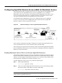
C H A P TER
2
Cisco AS5300 Configuration
This chapter describes how to configure the Cisco AS5300 to receive calls from the Cisco 1604,
Cisco 766, and remote modem users.
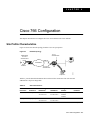
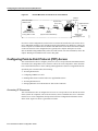
Site Profile Characteristics
Figure 2-1 shows the network topology from the Cisco AS5300’s perspective.
Figure 2-1
Network Topology
Cisco 766
remote LAN
DNS
server
10.2.2.3
10.1.1.10
255.255.255.0
Cisco 1604
remoteLAN
Four T1 PRI lines
PSTN/ISDN
Interface dialer
10.1.254.1
255.255.255.0
IP network
Modem
client
15580
Cisco
AS5300
Backhaul
router
Note Before you perform the configuration tasks in this chapter, be sure you understand the overall
dial case action plan described in the previous chapter “Dial Case Study Overview.”
Cisco AS5300 Configuration 2-1
Site Profile Characteristics
Table 2-1 provides detailed information about each end of the connection. This is the network
administrator’s top-level design table.
Table 2-1
Site Characteristics
Site
Hardware
WAN
IP Address
Ethernet
IP Address
Assigned Phone
Number
Host Name/
Username1
Username
Password1
Cisco
AS53002
10.1.254.1
255.255.255.03
10.1.1.10
255.255.255.0
40855512344
hq-sanjose
hq-sanjose-pw
Cisco 766
10.1.254.3
255.255.255.0
10.1.3.1
255.255.255.0
Directory number =
5305558084
soho-tahoe
tahoe-pw
Cisco 1604
10.1.254.4
255.255.255.0
10.1.4.1
255.255.255.0
Directory number =
5125554433
robo-austin
austin-pw
1.
2.
3.
4.
Make sure to use your own host names and passwords. For example soho-tahoe and tahoe-pw are for this case study’s purpose only.
The subnet 10.1.2.0 255.255.255.0 is used for the loopback interface and the local IP address pools.
This address is configured on the Cisco AS5300’s dialer interface.
This is the PRI telephone number assigned to the central site (hq-sanjose). This number is often called the hunt group number, which
distributes calls among the available B channels. All four PRI trunks on the Cisco AS5300 should be assigned to this number by the
PRI provider.
Cisco IOS Release 12.0 is running inside the access server. If the startup configuration is blank,
the following screen is displayed at bootup. The automatic setup script is engaged. Enter no when
you are asked the question, “Would you like to enter the initial configuration dialog? [yes]: no.”
In this case study, the Cisco AS5300 is manually configured using the Cisco IOS software.
The automatic setup script is not used.
Note To enhance readability throughout this chapter, the most important output fields are
highlighted with bold font. The commands you enter are also bold but are preceded by a router
prompt.
Copyright (c) 1994-1995 by cisco Systems, Inc.
AS5300 processor with 32768 Kbytes of main memory
program load complete, entry point: 0x80008000, size: 0xf4b10
Self decompressing the image : #################################################
################################################################################
################################################################################
################################################################################
################################################################################
################## [OK]
Restricted Rights Legend
Use, duplication, or disclosure by the Government is
subject to restrictions as set forth in subparagraph
(c) of the Commercial Computer Software - Restricted
Rights clause at FAR sec. 52.227-19 and subparagraph
(c) (1) (ii) of the Rights in Technical Data and Computer
Software clause at DFARS sec. 252.227-7013.
cisco Systems, Inc.
170 West Tasman Drive
San Jose, California 95134-1706
2-2
Dial Solutions Quick Configuration Guide
Site Profile Characteristics
Cisco Internetwork Operating System Software
IOS (tm) 5300 Software (C5300-JS-M), Version 12.0(x)
Copyright (c) 1986-1998 by cisco Systems, Inc.
Compiled Tue 07-Jul-98 15:26 by xxxx
Image text-base: 0x600088E8, data-base: 0x608F4000
cisco AS5300 (R4K) processor (revision A.04) with 32768K/8192K bytes of memory.
Processor board ID 04614948
R4700 processor, Implementation 33, Revision 1.0 (512KB Level 2 Cache)
Bridging software.
X.25 software, Version 3.0.0.
SuperLAT software copyright 1990 by Meridian Technology Corp).
TN3270 Emulation software.
Primary Rate ISDN software, Version 1.1.
Backplane revision 1
Manufacture Cookie is not programmed.
1 Ethernet/IEEE 802.3 interface(s)
1 FastEthernet/IEEE 802.3 interface(s)
96 terminal line(s)
4 Channelized T1/PRI port(s)
128K bytes of non-volatile configuration memory.
16384K bytes of processor board System flash (Read/Write)
4096K bytes of processor board Boot flash (Read/Write)
Cisco Internetwork Operating System Software
IOS (tm) 5300 Software (C5300-JS-M), Version 12.0(x),
Copyright (c) 1986-1998 by cisco Systems, Inc.
Compiled Tue 07-Jul-98 15:26 by xxx
00:00:50: %MICA-5-BOARDWARE_RUNNING: Slot 2 is running boardware version 2.5.0.8
--- System Configuration Dialog --At any point you may enter a question mark '?' for help.
Use ctrl-c to abort configuration dialog at any prompt.
Default settings are in square brackets '[]'.
Would you like to enter the initial configuration dialog? [yes]: no
Press RETURN to get started!
Router>
Note Use the show version command to determine if the access server is recognizing all of its
modems cards. For example, the output field “96 terminal line(s)” tells you that the chassis can find
all 96 integrated modems.
Cisco AS5300 Configuration 2-3
Overview of Tasks
Overview of Tasks
Perform the following steps to configure the access server:
•
Set up asynchronous shell services:
— “Step 1—Configuring the Host Name, Password, and Time Stamps” on page 5
— “Step 2—Configuring Local AAA Security” on page 6
— “Step 3—Configuring the Fast Ethernet 100BaseT Interface” on page 8
— “Step 4—Commissioning the T1 Controllers” on page 10
— “Step 5—Configuring the Serial Channels to Let Modem Calls Come in” on page 14
— “Step 6—Configuring the Modems and Lines” on page 18
— “Step 7—Testing Async Shell Connections” on page 19
•
Set up asynchronous PPP services:
— “Step 8—Setting Up IP Address Pools” on page 27
— “Step 9—Configuring the Group-Async Interface” on page 28
— “Step 10—Testing Async PPP Connections” on page 31
•
Set up synchronous PPP services:
— “Step 11—Configuring DDR” on page 36
— “Step 12—Configuring Definitions for Remote LAN Sites” on page 39
— “Step 13—Configuring a Backhaul Routing Protocol” on page 41
— “Step 14—Confirming the Final Running Configuration” on page 42
— “Step 15—Saving the Configuration” on page 44
— “Step 16—Testing Sync PPP Connections to Remote LANs” on page 44
— “Step 17—Adding More Remote LAN Sites as Needed” on page 44
2-4
Dial Solutions Quick Configuration Guide
Step 1—Configuring the Host Name, Password, and Time Stamps
Step 1—Configuring the Host Name, Password, and Time Stamps
Assign a host name to the Cisco AS5300, enable basic security, and turn on time stamping.
Configuring a host name allows you to distinguish between different network devices. Enable
passwords allow you to prevent unauthorized configuration changes. Time stamps help you trace
debug output for testing connections. Not knowing exactly when an event occurs hinders you from
examining background processes.
Configure
To configure the host name, enable password, and time stamps use the following commands
beginning in user EXEC mode:
Step
Command
Purpose
1
Router> enable
Enter privileged EXEC mode.
2
Router# configure terminal
Enter configuration commands, one per line. End
with CNTL/Z.
Enter global configuration mode1.
3
Router(config)# hostname hq-sanjose
Assign a host name to the access server2.
This host name is typically used during
authentication with PPP peers.
4
hq-sanjose(config)# enable secret letmein
Enter a secret enable password, which
secures privileged EXEC mode3.
5
hq-sanjose(config)# service password-encryption
Encrypt passwords in the configuration file
for greater security4.
6
hq-sanjose(config)# service timestamps debug datetime msec
hq-sanjose(config)# service timestamps log datetime msec
Enable millisecond time stamping on debug
and logging output. Time stamps are useful
for detailed access troubleshooting.
1.
2.
3.
4.
If the logging output generated by the access server interferes with your terminal screen, redisplay your current command line using the Tab key.
The step is verified by the router prompt changing from Router(config)# to hq-sanjose(config)#.
Make sure to change “letmein” to your own secret password.
Additional measures should be used, as the passwords are not strongly encrypted by today’s standards.
Verify
To verify the configuration:
•
Try logging in with your new enable password. Exit out of enable mode using the disable
command. The prompt changes from hq-sanjose# to hq-sanjose>. Enter the enable command
followed by your password. The show privilege command shows the current security privilege
level.
hq-sanjose# disable
hq-sanjose> enable
Password: letmein
hq-sanjose# show privilege
Current privilege level is 15
hq-sanjose#
Cisco AS5300 Configuration 2-5
Step 2—Configuring Local AAA Security
•
Enter the show running command:
hq-sanjose# show running
Building configuration...
Current configuration:
!
version 12.0
service timestamps debug datetime msec
service timestamps log datetime msec
service password-encryption
!
hostname hq-sanjose
!
enable secret 5 $1$.voA$9/8.Zoil3jeWJMP6hEE6U0
!
----- snip ----
Tips
If you have trouble:
•
•
•
Make sure Caps Lock is off.
Make sure you entered the correct passwords. Passwords are case sensitive.
Password protection is very important. Cisco highly recommends that you use the
show tech-support command to report system configuration information to Cisco TAC:
hq-sanjose# show tech-support ?
ipmulticast IP multicast related information
page
Page through output
password
Include passwords
rsvp
IP RSVP related information
<cr>
Step 2—Configuring Local AAA Security
The Cisco IOS security model to use on all Cisco devices is authentication, authorization, and
accounting (AAA). AAA provides the primary framework through which you set up access control
on the access server.
•
•
•
Authentication—Who are you?
Authorization—What can you do?
Accounting—What did you do?
In this case study, the same authentication method is used on all interfaces. AAA is set up to use the
local database configured on the router. This local database is created with the username
configuration commands.
Note After you finish setting up basic security, you can enhance the security solution by extending
it to an external TACACS+ or RADIUS server. This case study describes local AAA security only.
2-6
Dial Solutions Quick Configuration Guide
Configure
Configure
To configure local AAA security, use the following commands beginning in global configuration
mode:
Step
Command
Purpose
1
hq-sanjose(config)# username joe-admin password joe-password
Create a local login database
and username for yourself1.
This step also prevents you from
getting locked out of the access
server.
2
hq-sanjose(config)# aaa new-model
Initiate the AAA access control
system.
This step immediately locks
down login and PPP
authentication.
3
hq-sanjose(config)# aaa authentication login default local
Configure AAA to perform
login authentication using the
local username database.
The login keyword
authenticates shell/EXEC users.
4
hq-sanjose(config)# aaa authentication ppp default if-needed local
Configure PPP authentication to
use the local database if the
session was not already
authenticated by login.
1. Make sure to change “joe-admin” to your own username and “joe-password” to your own password.
Verify
To verify the configuration:
•
Try to log in with your username:password. Enter the login command at the EXEC shell prompt.
If you get in, the login authentication is working with your local username. Do not disconnect
your access server session until you can log in successfully. (If you get locked out, you will need
to perform password recovery by rebooting the access server.)
hq-sanjose# login
User Access Verification
Username: joe-admin
Password: joe-password
hq-sanjose#
•
Enter the show running command:
hq-sanjose# show running
Building configuration...
Current configuration:
!
version 12.0
service timestamps debug datetime msec
service timestamps log datetime msec
service password-encryption
!
hostname hq-sanjose
Cisco AS5300 Configuration 2-7
Step 3—Configuring the Fast Ethernet 100BaseT Interface
!
aaa new-model
aaa authentication login default local
aaa authentication ppp default if-needed local
enable secret 5 $1$.voA$9/8.Zoil3jeWJMP6hEE6U0
!
username joe-admin password 7 <removed>
!
----- snip ----
Step 3—Configuring the Fast Ethernet 100BaseT Interface
Assign an IP address, line speed, and duplex mode to the Fast Ethernet interface. The Fast Ethernet
interface supports 10- and 100-Mbps speeds.
The default priority search order for auto negotiating the line speed is as follows:
1 100Base-TX full duplex
2 100Base-TX half duplex
3 10Base-T full duplex
4 10Base-T half duplex
Configure
To configure the Fast ethernet 100BaseT interface, use the following commands beginning in global
configuration mode:
Step
Command
Purpose
1
hq-sanjose(config)# interface fastethernet 0
hq-sanjose(config-if)# ip address 10.1.1.10 255.255.255.0
Configure the IP address and subnet
mask on the Fast Ethernet interface.
2
hq-sanjose(config-if)# speed auto
Auto negotiate the line speed based on
the peer routers, hubs, and switch media.
3
hq-sanjose(config-if)# duplex auto
Auto negotiate duplex mode.
4
hq-sanjose(config-if)# no shutdown
%LINK-3-UPDOWN: Interface FastEthernet0, changed state to up
Bring up the interface1.
1. This command changes the state of the interface from administratively down to up.
Verify
To verify the configuration:
•
Enter the show ip interface brief command to view the interface’s status. The “up” display field
should appear under the Status and Protocol columns. The display fields “down” or
“administratively down” signify a connection problem.
hq-sanjose# show ip interface brief fastethernet 0
Interface
IP-Address
OK?
FastEthernet0
10.1.1.10
YES
2-8
Dial Solutions Quick Configuration Guide
Method
manual
Status
up
Protocol
up
Verify
•
Try pinging a device in your network, such as a backhaul router or the backbone gateway:
hq-sanjose# ping 10.1.1.1
Type escape sequence to abort.
Sending 5, 100-byte ICMP Echos to 10.1.1.1, timeout is 2 seconds:
!!!!!
Success rate is 100 percent (5/5), round-trip min/avg/max = 4/5/8 ms
•
Enter the show interface fastethernet 0 command to see detailed interface information.
Look for the display field “FastEthernet 0 is up, line protocol is up.” This means that
the access server sees its own sent and received keepalives.
hq-sanjose# show interface fastethernet 0
FastEthernet0 is up, line protocol is up
Hardware is DEC21140AE, address is 00e0.1e6b.2ffb (bia 00e0.1e6b.2ffb)
Internet address is 10.1.1.10 /24
MTU 1500 bytes, BW 100000 Kbit, DLY 100 usec, rely 255/255, load 1/255
Encapsulation ARPA, loopback not set, keepalive set (10 sec), auto duplex,
100BaseTX/FX, auto speed
ARP type: ARPA, ARP Timeout 04:00:00
Last input 00:00:05, output 00:00:05, output hang never
Last clearing of "show interface" counters never
Queueing strategy: fifo
Output queue 0/40, 0 drops; input queue 0/120, 0 drops
5 minute input rate 0 bits/sec, 0 packets/sec
5 minute output rate 0 bits/sec, 0 packets/sec
282 packets input, 68476 bytes, 0 no buffer
Received 282 broadcasts, 0 runts, 0 giants, 0 throttles
0 input errors, 0 CRC, 0 frame, 0 overrun, 0 ignored, 0 abort
0 watchdog, 0 multicast
0 input packets with dribble condition detected
176 packets output, 16936 bytes, 0 underruns
0 output errors, 0 collisions, 0 interface resets
0 babbles, 0 late collision, 0 deferred
0 lost carrier, 0 no carrier
0 output buffer failures, 0 output buffers swapped out
•
Enter the show running command:
hq-sanjose# show running
Building configuration...
Current configuration:
!
----- snip ---!
interface FastEthernet0
ip address 10.1.1.10 255.255.255.0
no ip directed-broadcast
no ip route-cache
no ip mroute-cache
duplex auto
speed auto
!
----- snip ----
Tips
If you have trouble:
•
•
Make sure the cable connections are not loose or disconnected.
Make sure you are using the correct IP address.
Cisco AS5300 Configuration 2-9
Step 4—Commissioning the T1 Controllers
Step 4—Commissioning the T1 Controllers
Configure the T1 controllers to allow calls to come into the access server. You must specify the
following information for each controller: framing type, line code type, clock source, and timeslot
assignments.
Configure
To configure the controllers, use the following commands beginning in global configuration mode:
Step
Command
Purpose
1
hq-sanjose(config)# isdn switch-type primary-ni
Enter your telco’s switch type.
This example uses primary national ISDN 1.
2
hq-sanjose(config)# controller t1 0
Enter controller configuration mode for the
first T1 controller, which is 0. The controller
ports are labeled 0 through 3 on the quad
T1/PRI card.
3
hq-sanjose(config-controller)# framing esf
Enter the T1 framing type.
This example uses extended super frame.
4
hq-sanjose(config-controller)# linecode b8zs
Enter the T1 line code type.
This example uses B8ZS.
5
hq-sanjose(config-controller)# clock source line primary
Configure the access server to get its primary
clocking from the T1 line assigned to
controller 0.
Line clocking comes from the remote switch.
6
hq-sanjose(config-controller)# pri-group timeslots 1-24
Assign all 24 T1 timeslots as ISDN PRI
channels1.
7
hq-sanjose(config-controller)# exit
Exit back to global configuration mode.
8
hq-sanjose(config#) controller
hq-sanjose(config-controller)#
hq-sanjose(config-controller)#
hq-sanjose(config-controller)#
hq-sanjose(config-controller)#
hq-sanjose(config-controller)#
t1 1
framing esf
linecode b8zs
clock source line secondary
pri-group timeslots 1-24
exit
Configure the second controller, controller
T1 1.
hq-sanjose(config#) controller
hq-sanjose(config-controller)#
hq-sanjose(config-controller)#
hq-sanjose(config-controller)#
hq-sanjose(config-controller)#
hq-sanjose(config-controller)#
hq-sanjose(config#) controller
hq-sanjose(config-controller)#
hq-sanjose(config-controller)#
hq-sanjose(config-controller)#
hq-sanjose(config-controller)#
hq-sanjose(config-controller)#
hq-sanjose(config#)
t1 2
framing esf
linecode b8zs
clock source internal
pri-group timeslots 1-24
exit
t1 3
framing esf
linecode b8zs
clock source internal
pri-group timeslots 1-24
exit
Configure the remaining two controllers.
9
Set the clocking to secondary. If the line
clocking from controller T1 0 fails, the access
server will receive its clocking from controller
T1 1.
Set both clocking entries to internal.
The primary and secondary clock sources
have already been assigned.
1. After you enter this command, a D-channel serial interface is instantly created (for example S0:23, S1:23, and so on) in the configuration file as well as the
individual B-channel serial interfaces (for example S0:0, S0:1, ...). The D-channel interface functions like a dialer for all the 23 B channels using the controller.
2-10
Dial Solutions Quick Configuration Guide
Verify
Verify
To verify the configuration:
•
Use the show controller t1 command. The output from this command enables you to determine
when and where errors occur. See the display field “Data in current interval.”
hq-sanjose# show controller t1
T1 0 is up.
No alarms detected.
Version info of slot 0: HW: 2, Firmware: 16, PLD Rev: 0
Manufacture Cookie Info:
EEPROM Type 0x0001, EEPROM Version 0x01, Board ID 0x42,
Board Hardware Version 1.0, Item Number 73-2217-4,
Board Revision A0, Serial Number 07557185,
PLD/ISP Version 0.0, Manufacture Date 17-Dec-1997.
Framing is ESF, Line Code is B8ZS, Clock Source is Line Primary.
Data in current interval (25 seconds elapsed):
0 Line Code Violations, 0 Path Code Violations
0 Slip Secs, 0 Fr Loss Secs, 0 Line Err Secs, 0 Degraded Mins
0 Errored Secs, 0 Bursty Err Secs, 0 Severely Err Secs, 0 Unavail Secs
Total Data (last 24 hours)
0 Line Code Violations, 0 Path Code Violations,
0 Slip Secs, 0 Fr Loss Secs, 0 Line Err Secs, 0 Degraded Mins,
0 Errored Secs, 0 Bursty Err Secs, 0 Severely Err Secs, 0 Unavail Secs
T1 1 is up.
No alarms detected.
Version info of slot 0: HW: 2, Firmware: 16, PLD Rev: 0
Manufacture Cookie Info:
EEPROM Type 0x0001, EEPROM Version 0x01, Board ID 0x42,
Board Hardware Version 1.0, Item Number 73-2217-4,
Board Revision A0, Serial Number 07557185,
PLD/ISP Version 0.0, Manufacture Date 17-Dec-1997.
Framing is ESF, Line Code is B8ZS, Clock Source is Line Secondary.
Data in current interval (827 seconds elapsed):
0 Line Code Violations, 0 Path Code Violations
0 Slip Secs, 0 Fr Loss Secs, 0 Line Err Secs, 0 Degraded Mins
0 Errored Secs, 0 Bursty Err Secs, 0 Severely Err Secs, 0 Unavail Secs
Total Data (last 24 hours)
0 Line Code Violations, 0 Path Code Violations,
0 Slip Secs, 0 Fr Loss Secs, 0 Line Err Secs, 0 Degraded Mins,
0 Errored Secs, 0 Bursty Err Secs, 0 Severely Err Secs, 0 Unavail Secs
T1 2 is administratively down.
Transmitter is sending remote alarm.
Receiver has loss of signal.
Version info of slot 0: HW: 2, Firmware: 16, PLD Rev: 0
Manufacture Cookie Info:
EEPROM Type 0x0001, EEPROM Version 0x01, Board ID 0x42,
Board Hardware Version 1.0, Item Number 73-2217-4,
Board Revision A0, Serial Number 07557185,
PLD/ISP Version 0.0, Manufacture Date 17-Dec-1997.
Framing is ESF, Line Code is B8ZS, Clock Source is Internal.
Data in current interval (868 seconds elapsed):
3 Line Code Violations, 0 Path Code Violations
0 Slip Secs, 868 Fr Loss Secs, 2 Line Err Secs, 0 Degraded Mins
0 Errored Secs, 0 Bursty Err Secs, 0 Severely Err Secs, 868 Unavail Secs
Total Data (last 24 hours)
182 Line Code Violations, 0 Path Code Violations,
1 Slip Secs, 86400 Fr Loss Secs, 125 Line Err Secs, 0 Degraded Mins,
0 Errored Secs, 0 Bursty Err Secs, 0 Severely Err Secs, 86400 Unavail Secs
T1 3 is administratively down.
Transmitter is sending remote alarm.
Receiver has loss of signal.
Version info of slot 0: HW: 2, Firmware: 16, PLD Rev: 0
Manufacture Cookie Info:
Cisco AS5300 Configuration 2-11
Step 4—Commissioning the T1 Controllers
EEPROM Type 0x0001, EEPROM Version 0x01, Board ID 0x42,
Board Hardware Version 1.0, Item Number 73-2217-4,
Board Revision A0, Serial Number 07557185,
PLD/ISP Version 0.0, Manufacture Date 17-Dec-1997.
Framing is ESF, Line Code is B8ZS, Clock Source is Internal.
Data in current interval (142 seconds elapsed):
0 Line Code Violations, 0 Path Code Violations
0 Slip Secs, 142 Fr Loss Secs, 0 Line Err Secs, 0 Degraded Mins
0 Errored Secs, 0 Bursty Err Secs, 0 Severely Err Secs, 142 Unavail Secs
Total Data (last 24 hours)
12 Line Code Violations, 0 Path Code Violations,
0 Slip Secs, 86400 Fr Loss Secs, 8 Line Err Secs, 0 Degraded Mins,
0 Errored Secs, 0 Bursty Err Secs, 0 Severely Err Secs, 86400 Unavail Secs
•
Enter the show controller t1 number command. If counters are increasing on a specific T1
controller, look more closely at the error statistics. Error counters are recorded for a 24-hour
period in 15-minute intervals. You must specify a specific controller number to see this detailed
information. Focus on the current interval.
In the following example, notice that the frame loss and line errors present in data intervals 1
through 4 were eventually cleared up in the current data interval.
Note Errors are reported to the controller’s counters each time an error is encountered.
Therefore, clear the counters using the clear controller t1 number command before you look for
current error statistics. Error counters stop increasing when the controller is configured correctly.
hq-sanjose# show controller t1 0
T1 0 is up.
No alarms detected.
Version info of slot 0: HW: 2, Firmware: 16, PLD Rev: 0
Manufacture Cookie Info:
EEPROM Type 0x0001, EEPROM Version 0x01, Board ID 0x42,
Board Hardware Version 1.0, Item Number 73-2217-4,
Board Revision A0, Serial Number 07557185,
PLD/ISP Version 0.0, Manufacture Date 17-Dec-1997.
Framing is ESF, Line Code is B8ZS, Clock Source is Line Primary.
Data in current interval (72 seconds elapsed):
0 Line Code Violations, 0 Path Code Violations
0 Slip Secs, 0 Fr Loss Secs, 0 Line Err Secs, 0 Degraded Mins
0 Errored Secs, 0 Bursty Err Secs, 0 Severely Err Secs, 0 Unavail Secs
Data in Interval 1:
0 Line Code Violations, 0 Path Code Violations
0 Slip Secs, 405 Fr Loss Secs, 14 Line Err Secs, 0 Degraded Mins
0 Errored Secs, 0 Bursty Err Secs, 0 Severely Err Secs, 405 Unavail Secs
Data in Interval 2:
0 Line Code Violations, 0 Path Code Violations
0 Slip Secs, 450 Fr Loss Secs, 1 Line Err Secs, 0 Degraded Mins
0 Errored Secs, 0 Bursty Err Secs, 0 Severely Err Secs, 450 Unavail Secs
Data in Interval 3:
0 Line Code Violations, 0 Path Code Violations
0 Slip Secs, 450 Fr Loss Secs, 1 Line Err Secs, 0 Degraded Mins
0 Errored Secs, 0 Bursty Err Secs, 0 Severely Err Secs, 450 Unavail Secs
Data in Interval 4:
0 Line Code Violations, 0 Path Code Violations
0 Slip Secs, 450 Fr Loss Secs, 2 Line Err Secs, 0 Degraded Mins
0 Errored Secs, 0 Bursty Err Secs, 0 Severely Err Secs, 450 Unavail Secs
-------------------------------- snip ------------------------------------------
2-12
Dial Solutions Quick Configuration Guide
Verify
•
Enter the show running command:
hq-sanjose# show running
Building configuration...
Current configuration:
!
----- snip ---!
isdn switch-type primary-ni
!
controller T1 0
framing esf
clock source line primary
linecode b8zs
pri-group timeslots 1-24
!
controller T1 1
framing esf
clock source line secondary
linecode b8zs
pri-group timeslots 1-24
!
controller T1 2
framing esf
clock source internal
linecode b8zs
pri-group timeslots 1-24
!
controller T1 3
framing esf
clock source internal
linecode b8zs
pri-group timeslots 1-24
!
----- snip ----
Tips
If you have trouble:
•
•
Make sure the controller reports “up.”
No errors should be reported in the current interval.
Cisco AS5300 Configuration 2-13
Step 5—Configuring the Serial Channels to Let Modem Calls Come in
Step 5—Configuring the Serial Channels to Let Modem Calls Come in
The async shell service is the first service to enable. Configure the D channels to allow incoming
voice calls to be routed to the integrated modems.
In the section “Configuration DDR,” the D channel configuration is expanded to also accept ISDN
synchronous PPP calls from the remote offices. Cisco recommends getting modem users up first.
Configure
To configure the serial channels, use the following commands beginning in global configuration
mode:
Step
Command
Purpose
1
hq-sanjose(config)# interface serial 0:23
Enter configuration mode for the D-channel serial
interface that corresponds to controller T1 01.
The behavior of S0:0 through S0:22 is controlled by
the configuration instructions provided for S0:23.
This concept is also true for the other remaining
D channel configurations.
2
hq-sanjose(config-if)# isdn incoming-voice modem
hq-sanjose(config-if)# no shutdown
Enable analog modem voice calls coming in over the
B channels to be connected to the integrated modems.
3
hq-sanjose(config-if)# exit
Exit back to global configuration mode.
4
hq-sanjose(config)# interface serial 1:23
hq-sanjose(config-if)# isdn incoming-voice modem
hq-sanjose(config-if)# no shutdown
hq-sanjose(config-if)# exit
hq-sanjose(config)# interface serial 2:23
hq-sanjose(config-if)# isdn incoming-voice modem
hq-sanjose(config-if)# no shutdown
hq-sanjose(config-if)# exit
hq-sanjose(config)# interface serial 3:23
hq-sanjose(config-if)# isdn incoming-voice modem
hq-sanjose(config-if)# no shutdown
hq-sanjose(config-if)# exit
hq-sanjose(config)#
Configure the three remaining D channels with the
same settings.
1. The D channel is the signaling channel.
2-14
Dial Solutions Quick Configuration Guide
Verify
Verify
To verify the configuration:
•
Launch a voice call into the access server using a standard POTS telephone. If you hear modem
squelch (tone) from the access server’s internal modem, the configuration works. See Figure 2-2.
Figure 2-2
PSTN/ISDN
Voice Test Call
POTS
Cisco AS5300 receiving
analog telephone call
•
Standard POTS
telephone dialing
555-1234
15987
PRI
555-1234
Enter the show interface serial 0:23 command. The term “spoofing” means that the interface is
presenting itself to the Cisco IOS software as up and operational. This interface can now receive
routes. There are 23 more channels behind this interface that you do not see (for example, S0:0,
S0:1, and so on). The D channel decides which serial channel to assign to an incoming call.
hq-sanjose# show interface serial 0:23
Serial0:23 is up, line protocol is up (spoofing)
Hardware is DSX1
MTU 1500 bytes, BW 64 Kbit, DLY 20000 usec, rely 255/255, load 1/255
Encapsulation PPP, loopback not set
DTR is pulsed for 1 seconds on reset
Last input 00:00:12, output 00:00:12, output hang never
Last clearing of "show interface" counters never
Input queue: 0/75/0 (size/max/drops); Total output drops: 0
Queueing strategy: weighted fair
Output queue: 0/1000/64/0 (size/max total/threshold/drops)
Conversations 0/1/256 (active/max active/max total)
Reserved Conversations 0/0 (allocated/max allocated)
5 minute input rate 0 bits/sec, 0 packets/sec
5 minute output rate 0 bits/sec, 0 packets/sec
937 packets input, 19612 bytes, 0 no buffer
Received 0 broadcasts, 0 runts, 2 giants, 0 throttles
2 input errors, 0 CRC, 0 frame, 0 overrun, 0 ignored, 0 abort
945 packets output, 4263 bytes, 0 underruns
0 output errors, 0 collisions, 4 interface resets
0 output buffer failures, 0 output buffers swapped out
3 carrier transitions
Timeslot(s) Used:24, Transmitter delay is 0 flags
Note The packet counters shown by the interface serial 0:23 command are for signaling
traffic only. Data traffic passes through S0:0 through S0:22.
Cisco AS5300 Configuration 2-15
Step 5—Configuring the Serial Channels to Let Modem Calls Come in
•
Enter the show isdn status command to view the ISDN layer information. This output shows that
layer 1 and layer 2 are enabled and active. Layer 3 shows the number of active ISDN calls, which
there are none currently.
hq-sanjose# show isdn status
The current ISDN Switchtype = primary-ni
ISDN Serial0:23 interface
Layer 1 Status:
ACTIVE
Layer 2 Status:
TEI = 0, State = MULTIPLE_FRAME_ESTABLISHED
Layer 3 Status:
No Active Layer 3 Call(s)
Activated dsl 0 CCBs = 0
Total Allocated ISDN CCBs = 0
ISDN Serial1:23 interface
Layer 1 Status:
ACTIVE
Layer 2 Status:
TEI = 0, State = MULTIPLE_FRAME_ESTABLISHED
Layer 3 Status:
No Active Layer 3 Call(s)
Activated dsl 1 CCBs = 0
Total Allocated ISDN CCBs = 0
ISDN Serial2:23 interface
Layer 1 Status:
ACTIVE
Layer 2 Status:
TEI = 0, State = MULTIPLE_FRAME_ESTABLISHED
Layer 3 Status:
No Active Layer 3 Call(s)
Activated dsl 2 CCBs = 0
Total Allocated ISDN CCBs = 0
ISDN Serial3:23 interface
Layer 1 Status:
ACTIVE
Layer 2 Status:
TEI = 0, State = MULTIPLE_FRAME_ESTABLISHED
Layer 3 Status:
No Active Layer 3 Call(s)
Activated dsl 3 CCBs = 0
Total Allocated ISDN CCBs = 0
Note the following information:
— Layer 1 Status should be “Active.”
— Layer 2 Status should be “Multiple_Frame_Established.” (It might take several seconds for
Layer 2 status to appear.)
— Layer 3 Status should be “No Active Layer 3 Call(s).”
•
Enter the show isdn service command to determine which channels have active calls and if all
the individual channels are in service. In this example notice there are 8 serial channels under
each D channel that calls cannot use. T1 lines are used in this case study (not E1).
hq-sanjose# show isdn service
PRI Channel Statistics:
ISDN Se0:23, Channel (1-31)
Activated dsl 0
State (0=Idle 1=Propose 2=Busy 3=Reserved 4=Restart 5=Maint)
0 0 2 0 0 0 0 0 0 0 0 0 0 0 0 0 0 0 0 0 0 0 0 3 3 3 3 3 3 3 3
Channel (1-31) Service (0=Inservice 1=Maint 2=Outofservice)
0 0 0 0 0 0 0 0 0 0 0 0 0 0 0 0 0 0 0 0 0 0 0 2 2 2 2 2 2 2 2
ISDN Se1:23, Channel (1-31)
2-16
Dial Solutions Quick Configuration Guide
Verify
Activated dsl 0
State (0=Idle 1=Propose 2=Busy 3=Reserved 4=Restart 5=Maint)
0 0 0 0 0 0 0 0 0 0 0 0 0 0 0 0 0 0 0 0 0 0 0 3 3 3 3 3 3 3 3
Channel (1-31) Service (0=Inservice 1=Maint 2=Outofservice)
0 0 0 0 0 0 0 0 0 0 0 0 0 0 0 0 0 0 0 0 0 0 0 2 2 2 2 2 2 2 2
ISDN Se2:23, Channel (1-31)
Activated dsl 0
State (0=Idle 1=Propose 2=Busy 3=Reserved 4=Restart 5=Maint)
0 0 0 0 0 0 0 0 0 0 0 0 0 0 0 0 0 0 0 0 0 0 0 3 3 3 3 3 3 3 3
Channel (1-31) Service (0=Inservice 1=Maint 2=Outofservice)
0 0 0 0 0 0 0 0 0 0 0 0 0 0 0 0 0 0 0 0 0 0 0 2 2 2 2 2 2 2 2
ISDN Se3:23, Channel (1-31)
Activated dsl 0
State (0=Idle 1=Propose 2=Busy 3=Reserved 4=Restart 5=Maint)
0 0 0 0 0 0 0 0 0 0 0 0 0 0 0 0 0 0 0 0 0 0 0 3 3 3 3 3 3 3 3
Channel (1-31) Service (0=Inservice 1=Maint 2=Outofservice)
0 0 0 0 0 0 0 0 0 0 0 0 0 0 0 0 0 0 0 0 0 0 0 2 2 2 2 2 2 2 2
•
Enter the show ip interface brief command to view the individual serial B channel interfaces.
In the following example, Serial 0:0 through Serial 0:22 are B channels and associated to
Serial 0:23.
hq-sanjose# show ip interface brief
Interface
IP-Address
Ethernet0
unassigned
FastEthernet0
10.1.1.10
Serial0:0
unassigned
Serial0:1
unassigned
Serial0:2
unassigned
Serial0:3
unassigned
Serial0:4
unassigned
Serial0:5
unassigned
Serial0:6
unassigned
Serial0:7
unassigned
Serial0:8
unassigned
Serial0:9
unassigned
Serial0:10
unassigned
Serial0:11
unassigned
Serial0:12
unassigned
Serial0:13
unassigned
Serial0:14
unassigned
Serial0:15
unassigned
Serial0:16
unassigned
Serial0:17
unassigned
Serial0:18
unassigned
Serial0:19
unassigned
Serial0:20
unassigned
Serial0:21
unassigned
Serial0:22
unassigned
Serial0:23
unassigned
•
OK?
YES
YES
YES
YES
YES
YES
YES
YES
YES
YES
YES
YES
YES
YES
YES
YES
YES
YES
YES
YES
YES
YES
YES
YES
YES
YES
Method
NVRAM
manual
unset
unset
unset
unset
unset
unset
unset
unset
unset
unset
unset
unset
unset
unset
unset
unset
unset
unset
unset
unset
unset
unset
unset
unset
Status
Protocol
administratively down down
up
up
down
down
down
down
down
down
down
down
down
down
down
down
down
down
down
down
down
down
down
down
down
down
down
down
down
down
down
down
down
down
down
down
down
down
down
down
down
down
down
down
down
down
down
down
down
down
down
down
Enter the show running command:
hq-sanjose# show running
Building configuration...
Current configuration:
!
---- snip ---!
interface Serial0:23
no ip address
no ip directed-broadcast
isdn incoming-voice modem
Cisco AS5300 Configuration 2-17
Step 6—Configuring the Modems and Lines
!
interface Serial1:23
no ip address
no ip directed-broadcast
isdn incoming-voice modem
!
interface Serial2:23
no ip address
no ip directed-broadcast
isdn incoming-voice modem
!
interface Serial3:23
no ip address
no ip directed-broadcast
isdn incoming-voice modem
!
---- snip ----
Tips
If you have trouble:
•
•
•
Be sure you have the correct ISDN switch type configured.
•
Make sure the show controller t1 command’s current output shows no errors occurring.
Make sure no wires or cables are loose.
The framing or line code types you entered might not match your telco’s settings. A Layer 2 error
indicates that the access server cannot communicate with the telco.
Step 6—Configuring the Modems and Lines
Modems and lines are configured after the ISDN channels are operational, and voice calls are
successfully routed to the modems. Each modem is directly mapped to a dedicated async line in the
access server. After this configuration is set up, the access server is ready to take modem calls.
The modem speed 115200 bps and hardware flow control are the defaults for integrated modems.
Configure
To configure the modems and asynchronous lines, use the following commands beginning in global
configuration mode:
Step
Command
Purpose
1
hq-sanjose(config)# line 1 96
Enter the range of modem lines to configure.
In this example, the access server has 96 integrate modems.
2
hq-sanjose(config-line)# autoselect ppp
hq-sanjose(config-line)# autoselect during-login
Enable remote PPP users to dial in, bypass the EXEC facility,
and automatically launch PPP on the line.1
Enter the autoselect during-login command to display the
username:password prompt after modems connect.
3
hq-sanjose(config-line)# modem inout
Support incoming and outgoing modem calls.
1. These two autoselect commands provide for transparent launching of shell and PPP services on the same lines.
2-18
Dial Solutions Quick Configuration Guide
Verify
Verify
Enter the show running command to verify the configuration:
hq-sanjose# show running
Building configuration...
Current configuration:
---- snip ---!
line 1 96
autoselect during-login
autoselect ppp
modem InOut
---- snip ----
Step 7—Testing Async Shell Connections
Now you are ready to send the first modem call into the Cisco AS5300. This step shows you how to
perform the test and track the async data path taken by a single modem call.
Conduct this test using a shell service, which verifies that the physical async data path is working.
This is the most efficient way to get quick test results in a simple test environment.
At this step, many administrators try to make complex services work such as PPP-based Web
browsing. Do not jump ahead. Many other elements still need to be configured. This step is provided
to ensure that the basic modem link is functioning and that the shell/EXEC prompt can be accessed
from a remote location. To avoid problems, take a layered approach to building a network.
Note To enhance readability of debug output messages, the significant display output fields are
highlighted with bold font.
Figure 2-3 shows the test lab environment used for this test case. The test PC is running a terminal
emulation program, such as Hyper Terminal. This program enables the test PC to make a
modem-to-modem connection with the Cisco AS5300 via the PSTN/ISDN network.
Cisco AS5300 Configuration 2-19
Step 7—Testing Async Shell Connections
Figure 2-3
Test Lab Environment
POTS
PSTN/ISDN
Step 2
Call atdt5551234
using the terminal
emultion program
PRI
555-1234
RS-232
Step 3
Interpret debug
messages
Step 1
Modem
Cisco AS5300
receiving call
from test PC
RS-232
console
Test PC
15990
Step 1
Enter debug
Administrator's PC
commands (configuration and logging)
Enter the following debug commands on the Cisco AS5300 to debug calls landing on the
integrated modems. These commands capture the call-switching module and ISDN
connection messages. After you are finished with the test, turn off all debugging with the
undebug all command.
hq-sanjose# debug modem csm
Modem Management Call Switching Module debugging is on
hq-sanjose# debug isdn q931
ISDN Q931 packets debugging is on
hq-sanjose# terminal monitor
% Console already monitors
Note The ISDN Q.931 messages display call information coming into the access server.
The modem call switching module captures the calls getting routed to the internal
modems. The terminal monitor ensures that your EXEC session is receiving the logging
and debug output.
Step 2
From a terminal emulation program running on the test PC, enter atdt followed by the
primary rate interface (PRI) phone number assigned to the Cisco AS5300. In this case
test, 5551234 is used.
If the modem successfully connects, you will see a connect message followed by the
terminal service EXEC login prompt. This is displayed on the test PC.
atdt5551234
CONNECT 24000/REL - MNP
User Access Verification
Username: joe-admin
Password: joe-password
hq-sanjose>
2-20
Dial Solutions Quick Configuration Guide
Step 7—Testing Async Shell Connections
Note The modem attached to the test PC sends out “CONNECT 24000/REL - MNP”
The Cisco AS5300 sends out “User Access Verification,” “Username:,” and
“Password:.” These messages are confirmation that you have end-to-end async shell
connectivity.
Step 3
For educational purposes, look at and interpret the debug messages that appear on the
administrator’s terminal screen as a result of Step 2. As the modem call came into the
access server, this debug output was created.
The following comments apply to the debug output example:
(a)
See 20:43:35.906 through 20:43:35.918.
The setup message is received. The bearer capability is a voice call as indicated by
0x8090A2. The calling party number is 5551111, the test PC’s phone number.
The called party number is 5551234, the access server’s dialed hunt group number.
(b)
See 20:43:35.938.
Modem 1/1 is assigned to the incoming voice call.
(c)
See 20:43:36.754 and 20:43:36.782.
The call successfully connects as indicated by the fields “TX
“RX <- CONNECT_ACK.”
(d)
->
CONNECT”
and
See 20:43:36.806.
The integrated modem waits to negotiate carrier with the remote modem.
*Mar 1 20:43:35.906: ISDN Se0:23: RX <- SETUP pd = 8 callref = 0x0001
*Mar 1 20:43:35.906:
Bearer Capability i = 0x8090A2
*Mar 1 20:43:35.910:
Channel ID i = 0xA98381
*Mar 1 20:43:35.914:
Calling Party Number i = '!', 0x80, '5551111'
*Mar 1 20:43:35.918:
Called Party Number i = 0xA1, '5551234'
*Mar 1 20:43:35.934: EVENT_FROM_ISDN::dchan_idb=0x27C878, call_id=0xB, ces=0x1
bchan=0x0, event=0x1, cause=0x0
*Mar 1 20:43:35.938: VDEV_ALLOCATE: slot 1 and port 1 is allocated.
*Mar 1 20:43:35.938: EVENT_FROM_ISDN:(000B): DEV_INCALL at slot 1 and port 1
*Mar 1 20:43:35.942: CSM_PROC_IDLE: CSM_EVENT_ISDN_CALL at slot 1, port 1
*Mar 1 20:43:35.946: Fast Ringing On at modem slot 1, port 1
*Mar 1 20:43:35.966: ISDN Se0:23: TX -> CALL_PROC pd = 8 callref = 0x8001
*Mar 1 20:43:35.970:
Channel ID i = 0xA98381
*Mar 1 20:43:35.978: ISDN Se0:23: TX -> ALERTING pd = 8 callref = 0x8001
*Mar 1 20:43:36.742: Fast Ringing Off at modem slot 1, port 1
*Mar 1 20:43:36.742: CSM_PROC_IC1_RING: CSM_EVENT_MODEM_OFFHOOK at slot 1, port
1
*Mar 1 20:43:36.754: ISDN Se0:23: TX -> CONNECT pd = 8 callref = 0x8001
*Mar 1 20:43:36.782: ISDN Se0:23: RX <- CONNECT_ACK pd = 8 callref = 0x0001
*Mar 1 20:43:36.798: EVENT_FROM_ISDN::dchan_idb=0x27C878, call_id=0xB, ces=0x1
bchan=0x0, event=0x4, cause=0x0
*Mar 1 20:43:36.802: EVENT_FROM_ISDN:(000B): DEV_CONNECTED at slot 1 and port 1
*Mar 1 20:43:36.806: CSM_PROC_IC4_WAIT_FOR_CARRIER: CSM_EVENT_ISDN_CONNECTED at
slot 1, port 1
Cisco AS5300 Configuration 2-21
Step 7—Testing Async Shell Connections
Every Q.931 message indicates whether the message was transmitted by the access server (TX ->)
or received by the access server (RX <-). Table 2-2 shows the most common message types used for
opening and closing connections. Information elements exist within each message type, as described
in Table 2-3.
Table 2-2
Debug Q.931 ISDN Messages
Message Type
Description
SETUP
Indicates that a SETUP message has been received to initiate call establishment between
PSTN end devices.
A key element to observe within the call setup message is the bearer capability.
CALL_PROC
Call proceeding. The network attempts to service the call. The switch is attempting to set up
a call through the ISDN network backbone.
CONNECT
The called side transmits “CONNECT” when the connection is made. The side that transmits
“CONNECT” is usually the side that receives the call, which is the called party.
CONNECT_ACK
Connect acknowledgment. Transmitted by the calling side to indicate that the “CONNECT”
message was received.
DISCONNECT
Indicates that the transmitting side is ending the call. This messages indicates who dropped
the call.
RELEASE
Indicates that the sending equipment is releasing the call and the associated channel.
RELEASE_COMP
Release complete. Indicates that the ISDN network has received the “RELEASE” message.
ISDN setup messages contain different information elements. See Table 2-3.
Table 2-3
Information Elements within an ISDN Setup Message
Message
Description
Bearer Capability
Indicates what kind of service the caller is requesting. For example, a 64K data call is
indicated by the bearer capability of 0x8890. An analog voice call is indicated by the value
0x8090A2.
pd
Indicates the protocol discriminator number, which is 8 for Q.931 messages.
callref
A number used by the access server and the switch to reference the call. Indicates the call
reference number in hexadecimal format. The field value indicates the number of calls made
from the router (outgoing calls) or the network (incoming calls). Note that the originator of
the SETUP message sets the high-order bit of the call reference number to 0.
The destination of the connection sets the high-order bit to 1 in subsequent call control
messages, such as the CONNECT message. For example, callref = 0x04 in the request
becomes callref = 0x84 in the response.
2-22
Cause i
Indicates the Information Element Identifier. The value depends on the field with which it is
associated. Refer to the ITU-T Q.931 specification for details about the possible values
associated with each field for which this identifier is relevant.
Channel ID
Indicates the Channel Identifier. The value 83 indicates any channel, 89 indicates the B1
channel, and 8A indicates the B2 channel. For more information about the Channel
Identifier, refer to ITU-T Recommendation Q.931.
Calling Party
Number
Identifies the phone number of the device that initiated the call.
In this case study, 5551111 is the directory number assigned to the telephone line used by
the test PC.
Dial Solutions Quick Configuration Guide
Step 7—Testing Async Shell Connections
Table 2-3
Information Elements within an ISDN Setup Message (Continued)
Message
Description
Called Party
Number
Identifies the called phone number that is used to reach another device.
Step 4
In this case study, 5551234 is the directory number assigned to the Cisco AS5300. The test
PC dialed this number to make a modem connection.
To determine the status of the modem call connected to the Cisco AS5300, use the
following modem management commands.
•
Enter the show user command to see which TTY line the call landed on:
hq-sanjose# show user
Line
User
* 0 con 0
joe-admin
2 tty 2
joe-admin
•
Host(s)
idle
Async interface
Idle Location
0
1
Enter the show line 2 command. Note that TTY 2 is associated with modem 1/1.
The state is currently idle because this command was entered after the user
disconnected.
hq-sanjose# show line 2
Tty Typ
Tx/Rx
A Modem
2 TTY 115200/115200 - inout
Roty AccO AccI
-
Uses
0
Noise
0
Overruns
0/0
Line 2, Location: "", Type: ""
Length: 24 lines, Width: 80 columns
Baud rate (TX/RX) is 115200/115200, no parity, 1 stopbits, 8 databits
Status: No Exit Banner
Capabilities: Hardware Flowcontrol In, Hardware Flowcontrol Out
Modem Callout, Modem RI is CD
Modem state: Idle
modem(slot/port)=1/1, state=IDLE
dsx1(slot/unit/channel)=NONE, status=VDEV_STATUS_UNLOCKED
Group codes:
0
Modem hardware state: CTS noDSR DTR RTS
Special Chars: Escape Hold Stop Start Disconnect Activation
^^x
none
none
Timeouts:
Idle EXEC
Idle Session
Modem Answer Session
Dispatch
00:10:00
never
none
not set
Idle Session Disconnect Warning
never
Login-sequence User Response
00:00:30
Autoselect Initial Wait
Tty Typ
Tx/Rx
A Modem Roty AccO AccI Uses
Noise
Overruns
not set
Modem type is unknown.
Session limit is not set.
Time since activation: never
Editing is enabled.
History is enabled, history size is 10.
DNS resolution in show commands is enabled
Full user help is disabled
Allowed transports are lat pad telnet rlogin v120. Preferred is lat.
No output characters are padded
No special data dispatching characters
Cisco AS5300 Configuration 2-23
Step 7—Testing Async Shell Connections
•
Enter the show modem log 1/1 command to view the information logged for
modem 1/1. The time stamps show when the event occurred. The most current events
begin at the bottom of the output.
hq-sanjose# show modem log 1/1
Modem 1/1 Events Log:
20:40:45: Startup Response: Microcom (Managed)
Modem (boot) firmware = 2.2(8) (1.0(5))
---- snip ---00:02:19: ISDN incoming calling number: 5551111
00:02:19: ISDN incoming called number: 5551234
00:02:13: Modem State event: Dialing/Answering
00:02:13: Modem State event: Incoming ring
00:02:13: Modem State event: Waiting for Carrier
00:02:13: RS232 event: RTS DTR CTS DSR noDCD noRI* noTST
00:02:01: Modem State event: Connected
00:02:01: Connection event: TX/RX Speed = 33600/33600, Modulation = V34
Direction = Answer, Protocol = reliable/LAPM, Compression = V42bis
00:02:02: RS232 event: RTS DTR CTS DSR DCD* noRI noTST
00:01:50: Modem Analog signal event: TX = -21, RX = -18, Signal to noise = 43
00:00:15: DTR event: DTR Off
00:00:15: Modem State event: Connected
00:00:15: End connection event: Retransmits for EC block (TX/RX) = 0/0
Duration = 0:01:43, Number of TX/RX char = 159/0
Local Disc Reason = DTR Drop
Remote Disc Reason = Unknown
00:00:15: Modem State event: Disconnecting
00:00:15: DTR event: DTR On
00:00:15: RS232 event: RTS DTR* CTS* DSR* noDCD* noRI* noTST*
•
Enter the show modem command. In the following example, the current active call is
on modem 1/1, which is functioning properly at 100%. An active call is indicated by
an asterisk (*).
hq-sanjose# show modem
Inc calls
Mdm Usage
Succ
Fail
1/0
0%
0
0
* 1/1
0%
1
0
1/2
0%
0
0
1/3
0%
0
0
1/4
0%
0
0
1/5
0%
0
0
1/6
0%
0
0
1/7
0%
0
0
1/8
0%
0
0
1/9
0%
0
0
1/10
0%
0
0
1/11
0%
0
0
---- snip -----
2-24
Dial Solutions Quick Configuration Guide
Out calls
Succ
Fail
0
0
0
0
0
0
0
0
0
0
0
0
0
0
0
0
0
0
0
0
0
0
0
0
Busied
Out
0
0
0
0
0
0
0
0
0
0
0
0
Failed
Dial
0
0
0
0
0
0
0
0
0
0
0
0
No
Answer
0
0
0
0
0
0
0
0
0
0
0
0
Succ
Pct.
0%
100%
0%
0%
0%
0%
0%
0%
0%
0%
0%
0%
Step 7—Testing Async Shell Connections
•
Enter the show controller t1 0 call-counters command, which shows you the DS0
timeslot used to carry the modem call. This example shows that timeslot 1 has
accepted one call for a total duration of 1 minute 30 seconds.
hq-sanjose# show controller t1 0 call-counters
T1 0:
DS0's Active: 0
DS0's Active High Water Mark: 0
TimeSlot
Type
TotalCalls
TotalDuration
1
pri
1
00:01:30
2
pri
0
00:00:00
3
pri
0
00:00:00
4
pri
0
00:00:00
5
pri
0
00:00:00
6
pri
0
00:00:00
7
pri
0
00:00:00
8
pri
0
00:00:00
9
pri
0
00:00:00
10
pri
0
00:00:00
11
pri
0
00:00:00
12
pri
0
00:00:00
13
pri
0
00:00:00
14
pri
0
00:00:00
15
pri
0
00:00:00
16
pri
0
00:00:00
17
pri
0
00:00:00
18
pri
0
00:00:00
19
pri
0
00:00:00
20
pri
0
00:00:00
21
pri
0
00:00:00
22
pri
0
00:00:00
23
pri
0
00:00:00
Total DS0's Active High Water Mark: 0
Cisco AS5300 Configuration 2-25
Step 7—Testing Async Shell Connections
•
To further troubleshoot modem problems, connect to a modem’s out-of-band
management port. For Microcom modems, use the modem at-mode slot/port
command. For MICA modems, use the show modem operational-status slot/port
command and the show modem configuration slot/port command.
hq-sanjose# modem at-mode 2/15
You are now entering AT command mode on modem (slot 2 / port 15).
Please type CTRL-C to exit AT command mode.
at@e1
MNP Class 10 K56flex Modem
MODEM HW: OEM 2W United States
Firmware Rev 3.3.20/85
Bootstrap Rev 3.0.4
DSP C36 Part/Rev
3635 4241
DSP C58 Part/Rev
3635 2041
DSP Controller Rev
42
DSP Data Pump Rev
4.2
NET ADDR:
FFFFFFFFFFFF
Connect Time
000:06:41
4 RTS 5 CTS 6 DSR 8 CD 20 DTR - RI
Disconnect Remote Local Mod Type
TX/RX Spd
TX/RX Spd Mask
Symbol Rate
TX/RX Carrier Freq
TX/RX States
TX/RX NLE
TX/RX Precoding
TX/RX Shaping
TX Preemphasis Index
V.34
24000 26400 BPS
NA BFFF Hex
3200 Hz
1829 1829 Hz
16
16
ON
ON
ON
ON
ON
ON
0
TX Lvl REG
TX Lvl RAM
TX Lvl Reduct
TX Lvl
RX Lvl
S/NR
S/DR
EQM
AVG EQM
Lower/Upper Edge
Phase Jitter Freq
Phase Jitter Amp
Far Echo Lvl
Round Trip Delay
Dropouts > 5dB
RTRNs Init/Accept
RRENs Init/Accept
BLER
RBS Counter
Digital Pad Detected
Max SECRXB
Max SECTXB
V8BIS STATUS
- 13 dBm
- 0 dB
1 dB
- 14 dBm
- 19 dBm
42
0
1C00 Hex
19BE Hex
150 3675 Hz
139 Hz
0.0 deg
138 N
0 msec
0
0
0
0
0
0000 Hex
0000 Hex
0 dB
67
67
NAK
OK
2-26
Dial Solutions Quick Configuration Guide
Step 8—Setting Up IP Address Pools
Step 8—Setting Up IP Address Pools
Create a pool of IP address to support remote nodes dialing in. As remote node devices connect, they
request an IP address from the central site.
It is important to determine how your intranet/Internet backbone will route packets to the addresses
in this pool. There are several ways to do this, such as using addresses off a subnet defined on the
access server (for example, on the loopback or Ethernet interface).
Note Administrators commonly create a loopback interface and new subnet if their existing
Ethernet subnet has all its IP addresses already consumed. Loopback interfaces are very stable and
do not go up and down as LAN interfaces may.
Configure
To set up the address pool, use the following commands beginning in global configuration mode:
Step
Command
Purpose
1
hq-sanjose(config)# interface loopback 0
Create loopback interface 0.
2
hq-sanjose(config-if)# ip address 10.1.2.1 255.255.255.0
Assign an IP subnet and address
to loopback 0. This subnet is
used for the creation of your IP
address pool1.
3
hq-sanjose(config-if)# exit
Exit back to global
configuration mode.
4
hq-sanjose(config)# ip local pool dialin_pool 10.1.2.2 10.1.2.97
Create a pool of IP addresses for
assigning to the remote nodes2.
5
hq-sanjose(config)# async-bootp dns-server 10.2.2.3 10.2.3.1
Specify the domain name
servers on the network, which
can be used for clients dialing in
with PPP.
1. This subnet is now dedicated to this Cisco AS5300 for remote node support. This subnet cannot be used in other places in your network.
2. A remote LAN is typically a router that has a next hop address and its own IP subnet. It also requires IP routing support from the backbone, which is commonly
accomplished with a static IP route. A remote node gets an IP address out of a central pool of IP addresses. Remote LANs and remote nodes are primarily
differentiated by this IP addressing scheme. Remote LANs can appear as remote nodes by using PAT.
Verify
Enter the show ip local pool command to verify the configuration:
hq-sanjose# show ip local pool
Pool
Begin
End
dialin_pool 10.1.2.2
10.1.2.97
Free
96
In use
0
Cache Size
20
Cisco AS5300 Configuration 2-27
Step 9—Configuring the Group-Async Interface
Step 9—Configuring the Group-Async Interface
The group-async interface is a template, which is used to control the configuration of all the async
interfaces on the access server. Async interfaces are lines that are running in PPP mode. An async
interface uses the same number as its corresponding line. Configuring the asynchronous interfaces
as a group-async saves you time and configuration file size.
Configure
To configure the group-async interface, use the following commands beginning in global
configuration mode:
Step
Command
Purpose
1
hq-sanjose(config)# interface group-async 1
Create the group-async interface.
2
hq-sanjose(config-if)# ip unnumbered loopback 0
To conserve IP address space, configure
the asynchronous interfaces as
unnumbered.
3
hq-sanjose(config-if)# encapsulation ppp
Enable PPP.
4
hq-sanjose(config-if)# async mode interactive
Configure interactive mode on the
asynchronous interfaces. Interactive
means that users can dial in and get to a
shell or PPP session on that line.
5
hq-sanjose(config-if)# ppp authentication chap pap
Enable CHAP and PAP authentication on
the interface during LCP negotiation.
The access server first requests to
authenticate with CHAP. If CHAP is
rejected by the remote client (modem),
then PAP authentication is requested.
6
hq-sanjose(config-if)# peer default ip address pool dialin_pool
Assign dial-in clients IP addresses from
the pool named dialin_pool.
7
hq-sanjose(config-if)# no cdp enable
Disable the Cisco discovery protocol.
8
hq-sanjose(config-if)# group-range 1 96
Specify the range of asynchronous
interfaces to include in the group, which is
usually equal to the number of modems
you have in the access server.
Verify
Enter the show running command. After completing Steps 1 through 9, the configuration looks
like this:
hq-sanjose# show running
Building configuration...
Current configuration:
!
version 12.0
service timestamps debug datetime msec
service timestamps log datetime msec
service password-encryption
!
hostname hq-sanjose
!
aaa new-model
aaa authentication login default local
2-28
Dial Solutions Quick Configuration Guide
Verify
aaa authentication ppp default if-needed local
enable secret 5 $1$.voA$9/8.Zoil3jeWJMP6hEE6U0
!
username joe-admin password 7 <removed>
!
async-bootp dns-server 10.2.2.3 10.2.3.1
isdn switch-type primary-ni
!
!
controller T1 0
framing esf
clock source line primary
linecode b8zs
pri-group timeslots 1-24
!
controller T1 1
framing esf
clock source line secondary
linecode b8zs
pri-group timeslots 1-24
!
controller T1 2
framing esf
clock source internal
linecode b8zs
pri-group timeslots 1-24
!
controller T1 3
framing esf
clock source internal
linecode b8zs
pri-group timeslots 1-24
!
interface Loopback0
ip address 10.1.2.1 255.255.255.0
no ip directed-broadcast
!
interface Ethernet0
no ip address
no ip directed-broadcast
no ip route-cache
no ip mroute-cache
shutdown
!
interface Serial0:23
no ip address
no ip directed-broadcast
isdn incoming-voice modem
no fair-queue
no cdp enable
!
interface Serial1:23
no ip address
no ip directed-broadcast
isdn incoming-voice modem
no fair-queue
no cdp enable
!
interface Serial2:23
no ip address
no ip directed-broadcast
isdn incoming-voice modem
no fair-queue
no cdp enable
Cisco AS5300 Configuration 2-29
Step 9—Configuring the Group-Async Interface
!
interface Serial3:23
no ip address
no ip directed-broadcast
isdn incoming-voice modem
no fair-queue
no cdp enable
!
interface FastEthernet0
ip address 10.1.1.10 255.255.255.0
no ip directed-broadcast
no ip route-cache
no ip mroute-cache
duplex auto
speed auto
!
interface Group-Async1
ip unnumbered Loopback0
no ip directed-broadcast
encapsulation ppp
async mode interactive
peer default ip address pool dialin_pool
no cdp enable
ppp authentication chap pap
group-range 1 96
!
ip local pool dialin_pool 10.1.2.2 10.1.2.97
!
!
line con 0
line 1 96
autoselect during-login
autoselect ppp
modem InOut
line aux 0
line vty 0 4
!
end
2-30
Dial Solutions Quick Configuration Guide
Step 10—Testing Async PPP Connections
Step 10—Testing Async PPP Connections
Now you are ready to send the first async PPP modem call into the Cisco AS5300. This step provides
you with a picture of the test lab followed by debug output for a successful connection.
Figure 2-3 shows the test lab environment used for this test. A test PC makes a PPP
modem-to-modem connection with the Cisco AS5300 via the PSTN/ISDN network.
Figure 2-4
Test Lab Environment
POTS
PSTN/ISDN
Step 2
Call atdt5551234
using the terminal
emultion program
PRI
555-1234
RS-232
Step 1
Enter debug
Administrator's PC
commands (configuration and logging)
Step 1
Test PC
Cisco AS5300
receiving call
from test PC
15990
Step 3
Interpret debug
messages
Modem
RS-232
console
Enter the following debugging commands on the Cisco AS5300:
hq-sanjose# debug ppp negotiation
PPP protocol negotiation debugging is on
hq-sanjose# debug ppp authentication
PPP authentication debugging is on
hq-sanjose# debug modem
Modem control/process activation debugging is on
hq-sanjose# debug ip peer
IP peer address activity debugging is on
hq-sanjose# show debug
General OS:
Modem control/process activation debugging is on
Generic IP:
IP peer address activity debugging is on
PPP:
PPP authentication debugging is on
PPP protocol negotiation debugging is on
hq-sanjose# terminal monitor
Cisco AS5300 Configuration 2-31
Step 10—Testing Async PPP Connections
Step 2
From a terminal emulation program running on the test PC, enter atdt followed by the
telephone number assigned to the Cisco AS5300. In this case test, 5551234 is used.
atdt5551234
CONNECT 24000/REL - MNP
User Access Verification
Username: joe-admin
Password: joe-password
hq-sanjose>
Step 3
Interpret the debug messages that appear on the administrator’s terminal screen as a result
of Step 2. As the modem call comes into the access server, debug output is created.
Note When examining PPP between two remote peers, first check to see if both sides
get through LCP negotiation. If they do, move on to check authentication.
After authentication is successful, check IPCP negotiation.
The following comments apply to the debug output example, which spans over the next
few pages. Locate the time stamps in the debug output then interpret the call behavior.
2-32
(a)
See 21:34:56.958.
A modem call comes into the access server on TTY line 4.
(b)
See 21:34:59.722 through 21:34:59.734.
An incoming PPP frame is recognized, so PPP is launched on TTY line 4.
(c)
See 21:34:59.790.
The test PC gets assigned an IP address from the address pool set up on the access
server. The address is 10.1.2.2.
(d)
See 21:35:01.798.
Interface async 4 comes up. After PPP launches, TTY line 4 becomes async
interface 4.
(e)
See 21:35:02.718.
Incoming config request (I CONFREQ). The remote test PC requests a set of
options to be negotiated. The PC asks the Cisco AS5300 to support the callback
option.
(f)
See 21:35:02.738.
Outgoing config reject (O CONFREJ). The Cisco AS5300 rejects this option,
because the access server is not configured to support Microsoft Callback in this
case study.
(g)
See 21:35:02.850.
Incoming config request (I CONFREQ). The test PC requests a new set of options.
(h)
See 21:35:02.862.
Outgoing config acknowledgment (O CONFACK). The Cisco AS5300 accepts the
new set of options.
(i)
See 21:35:03.978.
LCP is now open (LCP: State is Open). Both sides have acknowledged
(CONFACK) the other side’s configuration request (CONFREQ).
Dial Solutions Quick Configuration Guide
Step 10—Testing Async PPP Connections
(j)
See 21:35:03.978.
After LCP negotiates, authentication starts. Authentication must happen before any
network protocols, such as IP, are delivered. Both sides authenticate with the method
negotiated during LCP. The Cisco AS5300 is authenticating the test PC using
CHAP. The test PC is not authenticating the access server in this test case.
(k)
See 21:35:03.982.
Outgoing challenge from hq-sanjose.
(l)
See 21:35:04.162.
Incoming CHAP response from the test PC, which is shows the username
joe-admin.
(m) See 21:35:04.182.
An outgoing success is sent from the NAS—authentication is successful.
(n)
See 21:35:04.186.
PPP is up. The Cisco AS5300 PPP link is now open and available to negotiate any
network protocols supported by both peers.
(o)
See 21:35:04.314 through 21:35:04.322.
The test PC requests support for Microsoft Point-to-Point Compression (MPPC).
The Cisco AS5300 rejects this request. The access server’s integrated modems
already support hardware compression, and the Cisco IOS is not configured to
support software compression.
(p)
See 21:35:07.274 through 21:35:07.478.
The primary and secondary DNS addresses are negotiated. At first, the test PC asks
for 0.0.0.0. addresses. The access server sends out a CONFNAK and supplies the
correct values. Values include an IP address from the pool, the primary DNS
address, and the backup DNS address.
(q)
See 21:35:07.426.
The test PC sends an incoming request saying that the new values are accepted.
Whenever the access server sends out a CONFNAK that includes values, the test PC
still needs to come back and report acceptance of the new values.
(r)
See 21:35:07.458 through 21:35:07.490.
An outgoing CONFACK is sent for IPCP. The state is open for IPCP. A route is
negotiated for the IPCP peer, which is 10.1.2.2.
Cisco AS5300 Configuration 2-33
Step 10—Testing Async PPP Connections
Note To enhance readability of debug output messages, significant display output fields are
highlighted with bold font.
hq-sanjose#
*Mar 1 21:34:56.958:
*Mar 1 21:34:56.962:
*Mar 1 21:34:56.970:
*Mar 1 21:34:56.978:
*Mar 1 21:34:59.722:
*Mar 1 21:34:59.726:
*Mar 1 21:34:59.730:
*Mar 1 21:34:59.730:
*Mar 1 21:34:59.734:
*Mar 1 21:34:59.746:
*Mar 1 21:34:59.746:
*Mar 1 21:34:59.786:
*Mar 1 21:34:59.790:
*Mar 1 21:34:59.794:
*Mar 1 21:34:59.794:
*Mar 1 21:35:01.798:
*Mar 1 21:35:01.834:
*Mar 1 21:35:01.838:
*Mar 1 21:35:01.842:
*Mar 1 21:35:01.846:
*Mar 1 21:35:01.850:
*Mar 1 21:35:01.854:
*Mar 1 21:35:01.854:
*Mar 1 21:35:01.858:
*Mar 1 21:35:02.718:
*Mar 1 21:35:02.722:
*Mar 1 21:35:02.726:
*Mar 1 21:35:02.726:
*Mar 1 21:35:02.730:
*Mar 1 21:35:02.730:
*Mar 1 21:35:02.738:
*Mar 1 21:35:02.738:
*Mar 1 21:35:02.850:
*Mar 1 21:35:02.854:
*Mar 1 21:35:02.854:
*Mar 1 21:35:02.858:
*Mar 1 21:35:02.858:
*Mar 1 21:35:02.862:
*Mar 1 21:35:02.866:
*Mar 1 21:35:02.870:
*Mar 1 21:35:02.870:
*Mar 1 21:35:02.874:
*Mar 1 21:35:03.842:
*Mar 1 21:35:03.842:
*Mar 1 21:35:03.846:
*Mar 1 21:35:03.850:
*Mar 1 21:35:03.854:
*Mar 1 21:35:03.854:
*Mar 1 21:35:03.858:
*Mar 1 21:35:03.962:
*Mar 1 21:35:03.966:
*Mar 1 21:35:03.966:
*Mar 1 21:35:03.970:
*Mar 1 21:35:03.974:
*Mar 1 21:35:03.974:
*Mar 1 21:35:03.978:
*Mar 1 21:35:03.978:
*Mar 1 21:35:03.982:
2-34
Dial Solutions Quick Configuration Guide
TTY4: DSR came up
TTY4: Modem: IDLE->READY
TTY4: EXEC creation
TTY4: set timer type 10, 30 seconds
TTY4: Autoselect(2) sample 7E
TTY4: Autoselect(2) sample 7EFF
TTY4: Autoselect(2) sample 7EFF7D
TTY4: Autoselect(2) sample 7EFF7D23
TTY4 Autoselect cmd: ppp negotiate
TTY4: EXEC creation
TTY4: create timer type 1, 600 seconds
ip_get_pool: As4: using pool default
ip_get_pool: As4: returning address = 10.1.2.2
TTY4: destroy timer type 1 (OK)
TTY4: destroy timer type 0
%LINK-3-UPDOWN: Interface Async4, changed state to up
As4 PPP: Treating connection as a dedicated line
As4 PPP: Phase is ESTABLISHING, Active Open
As4 LCP: O CONFREQ [Closed] id 1 len 25
As4 LCP:
ACCM 0x000A0000 (0x0206000A0000)
As4 LCP:
AuthProto CHAP (0x0305C22305)
As4 LCP:
MagicNumber 0x64E923A8 (0x050664E923A8)
As4 LCP:
PFC (0x0702)
As4 LCP:
ACFC (0x0802)
As4 LCP: I CONFREQ [REQsent] id 3 len 23
As4 LCP:
ACCM 0x000A0000 (0x0206000A0000)
As4 LCP:
MagicNumber 0x00472467 (0x050600472467)
As4 LCP:
PFC (0x0702)
As4 LCP:
ACFC (0x0802)
As4 LCP:
Callback 6 (0x0D0306)
As4 LCP: O CONFREJ [REQsent] id 3 len 7
As4 LCP:
Callback 6 (0x0D0306)
As4 LCP: I CONFREQ [REQsent] id 4 len 20
As4 LCP:
ACCM 0x000A0000 (0x0206000A0000)
As4 LCP:
MagicNumber 0x00472467 (0x050600472467)
As4 LCP:
PFC (0x0702)
As4 LCP:
ACFC (0x0802)
As4 LCP: O CONFACK [REQsent] id 4 len 20
As4 LCP:
ACCM 0x000A0000 (0x0206000A0000)
As4 LCP:
MagicNumber 0x00472467 (0x050600472467)
As4 LCP:
PFC (0x0702)
As4 LCP:
ACFC (0x0802)
As4 LCP: TIMEout: State ACKsent
As4 LCP: O CONFREQ [ACKsent] id 2 len 25
As4 LCP:
ACCM 0x000A0000 (0x0206000A0000)
As4 LCP:
AuthProto CHAP (0x0305C22305)
As4 LCP:
MagicNumber 0x64E923A8 (0x050664E923A8)
As4 LCP:
PFC (0x0702)
As4 LCP:
ACFC (0x0802)
As4 LCP: I CONFACK [ACKsent] id 2 len 25
As4 LCP:
ACCM 0x000A0000 (0x0206000A0000)
As4 LCP:
AuthProto CHAP (0x0305C22305)
As4 LCP:
MagicNumber 0x64E923A8 (0x050664E923A8)
As4 LCP:
PFC (0x0702)
As4 LCP:
ACFC (0x0802)
As4 LCP: State is Open
As4 PPP: Phase is AUTHENTICATING, by this end
As4 CHAP: O CHALLENGE id 1 len 26 from "hq-sanjose"
Step 10—Testing Async PPP Connections
*Mar 1 21:35:04.162:
*Mar 1 21:35:04.170:
*Mar 1 21:35:04.182:
*Mar 1 21:35:04.186:
*Mar 1 21:35:04.190:
*Mar 1 21:35:04.194:
*Mar 1 21:35:04.282:
*Mar 1 21:35:04.282:
06002D0F01)
*Mar 1 21:35:04.286:
*Mar 1 21:35:04.290:
*Mar 1 21:35:04.298:
*Mar 1 21:35:04.306:
*Mar 1 21:35:04.310:
06002D0F01)
*Mar 1 21:35:04.314:
*Mar 1 21:35:04.318:
01)
*Mar 1 21:35:04.318:
00104)
*Mar 1 21:35:04.322:
*Mar 1 21:35:04.326:
*Mar 1 21:35:04.330:
*Mar 1 21:35:04.334:
*Mar 1 21:35:04.338:
*Mar 1 21:35:05.186:
anged state to up
*Mar 1 21:35:07.274:
*Mar 1 21:35:07.278:
*Mar 1 21:35:07.282:
*Mar 1 21:35:07.286:
*Mar 1 21:35:07.294:
*Mar 1 21:35:07.298:
*Mar 1 21:35:07.302:
*Mar 1 21:35:07.310:
*Mar 1 21:35:07.426:
*Mar 1 21:35:07.430:
*Mar 1 21:35:07.434:
*Mar 1 21:35:07.442:
*Mar 1 21:35:07.446:
*Mar 1 21:35:07.450:
*Mar 1 21:35:07.450:
*Mar 1 21:35:07.454:
*Mar 1 21:35:07.458:
*Mar 1 21:35:07.462:
*Mar 1 21:35:07.466:
*Mar 1 21:35:07.474:
*Mar 1 21:35:07.478:
*Mar 1 21:35:07.490:
As4
As4
As4
As4
As4
As4
As4
As4
CHAP: I RESPONSE id 1 len 26 from "joe-admin"
AUTH: Started process 0 pid 47
CHAP: O SUCCESS id 1 len 4
PPP: Phase is UP
IPCP: O CONFREQ [Not negotiated] id 1 len 10
IPCP:
Address 10.1.2.1 (0x03060A010201)
IPCP: I CONFREQ [REQsent] id 1 len 28
IPCP:
CompressType VJ 15 slots CompressSlotID (0x02
As4
As4
As4
As4
As4
IPCP:
Address 0.0.0.0 (0x030600000000)
IPCP:
PrimaryDNS 0.0.0.0 (0x810600000000)
IPCP:
SecondaryDNS 0.0.0.0 (0x830600000000)
IPCP: O CONFREJ [REQsent] id 1 len 10
IPCP:
CompressType VJ 15 slots CompressSlotID (0x02
As4 CCP: I CONFREQ [Not negotiated] id 1 len 15
As4 CCP:
MS-PPC supported bits 0x00000001 (0x1206000000
As4 CCP:
Stacker history 1 check mode EXTENDED (0x11050
As4 LCP: O PROTREJ [Open] id 3 len 21 protocol CCP
As4 LCP: (0x80FD0101000F12060000000111050001)
As4 LCP: (0x04)
As4 IPCP: I CONFACK [REQsent] id 1 len 10
As4 IPCP:
Address 10.1.2.1 (0x03060A010201)
%LINEPROTO-5-UPDOWN: Line protocol on Interface Async4, ch
As4 IPCP: I CONFREQ [ACKrcvd] id 2 len 22
As4 IPCP:
Address 0.0.0.0 (0x030600000000)
As4 IPCP:
PrimaryDNS 0.0.0.0 (0x810600000000)
As4 IPCP:
SecondaryDNS 0.0.0.0 (0x830600000000)
As4 IPCP: O CONFNAK [ACKrcvd] id 2 len 22
As4 IPCP:
Address 10.1.2.2 (0x03060A010202)
As4 IPCP:
PrimaryDNS 10.2.2.3 (0x81060A020203)
As4 IPCP:
SecondaryDNS 10.2.3.1 (0x83060A020301)
As4 IPCP: I CONFREQ [ACKrcvd] id 3 len 22
As4 IPCP:
Address 10.1.2.2 (0x03060A010202)
As4 IPCP:
PrimaryDNS 10.2.2.3 (0x81060A020203)
As4 IPCP:
SecondaryDNS 10.2.3.1 (0x83060A020301)
ip_get_pool: As4: validate address = 10.1.2.2
ip_get_pool: As4: using pool default
ip_get_pool: As4: returning address = 10.1.2.2
set_ip_peer_addr: As4: address = 10.1.2.2 (3) is redundant
As4 IPCP: O CONFACK [ACKrcvd] id 3 len 22
As4 IPCP:
Address 10.1.2.2 (0x03060A010202)
As4 IPCP:
PrimaryDNS 10.2.2.3 (0x81060A020203)
As4 IPCP:
SecondaryDNS 10.2.3.1 (0x83060A020301)
As4 IPCP: State is Open
As4 IPCP: Install route to 10.1.2.2
hq-sanjose# undebug all
All possible debugging has been turned off
Note After you finish testing, turn off all debugging with the undebug all command. Isolating the
display of debug output helps you efficiently build a network. Debug only at the components that
you have built so far.
Cisco AS5300 Configuration 2-35
Step 11—Configuring DDR
Step 11—Configuring DDR
Dial-on-demand routing (DDR) provides a mechanism to establish and maintain connectivity over
a circuit switched network, such as the PSTN. DDR also supports remote LANs by maintaining
IP routes to the remote sites when they are not connected.
Configure
To configure the dialer interfaces, use the following commands beginning in global configuration
mode:
Step
Command
Purpose
1
hq-sanjose(config)# interface dialer 1
hq-sanjose(config-if)# ip address 10.1.254.1 255.255.255.0
Create interface dialer 1 and enable IP routing.
2
hq-sanjose(config-if)# exit
Exit back to global configuration mode.
3
hq-sanjose(config)# interface serial 0:23
hq-sanjose(config-if)# dialer rotary-group 1
hq-sanjose(config-if)# exit
Group serial 0’s channels into dialer 1.
4
hq-sanjose(config)# interface
hq-sanjose(config-if)# dialer
hq-sanjose(config-if)# exit
hq-sanjose(config)# interface
hq-sanjose(config-if)# dialer
hq-sanjose(config-if)# exit
hq-sanjose(config)# interface
hq-sanjose(config-if)# dialer
hq-sanjose(config-if)# exit
Group the remaining serial channels into
dialer 1.
serial 1:23
rotary-group 1
serial 2:23
rotary-group 1
serial 3:23
rotary-group 1
5
hq-sanjose(config)# interface dialer 1
Now with all the D channels grouped together,
return to dialer 1.
6
hq-sanjose(config-if)# encapsulation ppp
Encapsulate the packets with PPP.
7
hq-sanjose(config-if)# peer default ip address pool dialin_pool
Assign an address pool to interface dialer 1.
This step supports remote node ISDN devices,
such as those running Easy IP and PAT1.
8
hq-sanjose(config-if)# dialer in-band
Specify that this is an in-band dialer interface,
which enables passing the phone number
across the D channel.
9
hq-sanjose(config-if)# dialer idle-timeout 1800
Configure the idle timeout, which is set to
1800 seconds (30 minutes) in this example2.
10
hq-sanjose(config-if)# dialer-group 2
Define the interesting packets, which are
packets that reset the idle timer or trigger calls.
This dialer filter is defined by the dialer-list 2
command. See Step 173.
11
hq-sanjose(config-if)# ppp multilink
Enable PPP multilink, which fragments and
reassembles packets among bundled B
channels.
12
hq-sanjose(config-if)# ppp authentication chap pap
Enable CHAP and PAP authentication. CHAP
is used first. PAP is the second choice.
13
hq-sanjose(config-if)# no fair-queue
Disable fair queuing.
14
hq-sanjose(config-if)# no cdp enable
Disable the Cisco discovery protocol, unless
you are using it for a specific purpose.
15
hq-sanjose(config-if)# no ip mroute-cache
Turn off multicast route caching.
2-36
Dial Solutions Quick Configuration Guide
Verify
Step
Command
Purpose
16
hq-sanjose(config-if)# exit
Return to global configuration mode.
17
hq-sanjose(config)# dialer-list 2 protocol ip permit
Define a DDR dialer-list to allow any IP traffic
to maintain the connection. Any IP packet will
maintain the DDR session.
Minor or extensive tuning of your dialer list
might be required to control costs in your
environment.3
1. These users will also need a username and password.
2. Other environments might require shorter timeouts. The default is 120 seconds.
3. The dialer-group command and dialer-list command must use the same number. To monitor the idle timer value and the packets that reset it, use the debug
dialer packet command and show dialer command.
Verify
To verify the configuration:
•
Enter the show dialer command. This command shows you the state associated with each
IP interface. Notice that each individual serial channel is actually a dialer interface.
hq-sanjose# show dialer
Dialer1 - dialer type = IN-BAND SYNC NO-PARITY
Idle timer (1800 secs), Fast idle timer (20 secs)
Wait for carrier (30 secs), Re-enable (15 secs)
Dial String
Successes
Failures
Last called
Last status
Serial0:0 - dialer type = ISDN
Idle timer (1800 secs), Fast idle timer (20 secs)
Wait for carrier (30 secs), Re-enable (15 secs)
Dialer state is idle
Serial0:1 - dialer type = ISDN
Idle timer (1800 secs), Fast idle timer (20 secs)
Wait for carrier (30 secs), Re-enable (15 secs)
Dialer state is idle
Serial0:2 - dialer type = ISDN
Idle timer (1800 secs), Fast idle timer (20 secs)
Wait for carrier (30 secs), Re-enable (15 secs)
Dialer state is idle
----- snip -----
•
Enter the show running command:
hq-sanjose# show running
Building configuration...
Current configuration:
!
---- snip ---!
interface Serial0:23
no ip address
no ip directed-broadcast
dialer rotary-group 1
isdn incoming-voice modem
!
interface Serial1:23
Cisco AS5300 Configuration 2-37
Step 11—Configuring DDR
no ip address
no ip directed-broadcast
dialer rotary-group 1
isdn incoming-voice modem
!
interface Serial2:23
no ip address
no ip directed-broadcast
dialer rotary-group 1
isdn incoming-voice modem
!
interface Serial3:23
no ip address
no ip directed-broadcast
dialer rotary-group 1
isdn incoming-voice modem
!
---- snip ---!
interface Dialer1
ip address 10.1.254.1 255.255.255.0
no ip directed-broadcast
encapsulation ppp
no ip mroute-cache
dialer in-band
dialer idle-timeout 1800
dialer-group 2
peer default ip address pool dialin_pool
no fair-queue
no cdp enable
ppp authentication chap pap
ppp multilink
!
dialer-list 2 protocol ip permit
!
---- snip ----
2-38
Dial Solutions Quick Configuration Guide
Step 12—Configuring Definitions for Remote LAN Sites
Step 12—Configuring Definitions for Remote LAN Sites
You must configure additional parameters to enable synchronous PPP services for the remote sites.
Each remote site must have the following three entries configured on the Cisco AS5300:
•
•
•
Username and password
Static route
Dialer map to support IP connectivity with the remote peer
Table 2-4 summarizes the critical parameters used by DDR, which works primarily at the addressing
layer. These routes are stored in the routing table when the sites are not connected.
Table 2-4
Site Characteristics
Router
Name
Password
WAN
IP Address
Ethernet
IP Address
Assigned Phone
Number
Site
Hardware
hq-sanjose
hq-sanjose-pw
10.1.254.1
255.255.255.0
10.1.1.10
255.255.255.0
4085551234
Cisco AS5300
soho-tahoe
tahoe-pw
10.1.254.3
255.255.255.0
10.1.3.1
255.255.255.0
5305558084
Cisco 766
robo-austin
austin-pw
10.1.254.4
255.255.255.0
10.1.4.1
255.255.255.0
Cisco 1604
5125554433
Configure
To enable the remote LANs to dial into the Cisco AS5300, use the following commands beginning
in global configuration mode:
Step
Command
Purpose
1
hq-sanjose(config)# username robo-austin password austin-pw
Specify the robo-austin
username and
password1.
2
hq-sanjose(config)# ip route 10.1.4.0 255.255.255.0 10.1.254.4 permanent
Enable IP routing for
the robo-austin subnet.
3
hq-sanjose(config)# username soho-tahoe password tahoe-pw
Specify the soho-tahoe
username and
password1.
4
hq-sanjose(config)# ip route 10.1.3.0 255.255.255.0 10.1.254.3 permanent
Enable IP routing for
the soho-tahoe subnet.
5
hq-sanjose(config)# interface dialer 1
Enter interface dialer 1.
6
hq-sanjose(config-if)# dialer map ip 10.1.254.4 name robo-austin #
Create a dialer map
entry to the robo-austin
router2.
7
hq-sanjose(config-if)# dialer map ip 10.1.254.3 name soho-tahoe #
Create a dialer map
entry to the soho-tahoe
router2.
1. Make sure to use your own usernames and passwords for the remote sites.
2. In this case study, hq-sanjose does not dial out to the remote sites. The pound sign (#) is used to map the remote site’s name to the IP address.
Cisco AS5300 Configuration 2-39
Step 12—Configuring Definitions for Remote LAN Sites
Verify
Enter the show running command:
hq-sanjose# show running
Building configuration...
Current configuration:
!
---- snip ---!
username joe-admin password 7 <removed>
username robo-austin password 7 <removed>
username soho-tahoe password 7 <removed>
!
---- snip ---!
interface Dialer1
ip address 10.1.254.1 255.255.255.0
no ip directed-broadcast
encapsulation ppp
no ip mroute-cache
dialer in-band
dialer idle-timeout 1800
dialer map ip 10.1.254.3 name soho-tahoe #
dialer map ip 10.1.254.4 name robo-austin #
dialer-group 2
peer default ip address pool dialin_pool
no fair-queue
no cdp enable
ppp authentication chap pap
ppp multilink
!
---- snip ---!
ip local pool dialin_pool 10.1.2.2 10.1.2.97
ip route 10.1.3.0 255.255.255.0 10.1.254.3 permanent
ip route 10.1.4.0 255.255.255.0 10.1.254.4 permanent
!
dialer-list 2 protocol ip permit
!
---- snip ----
Tips
•
Dialer mapping provides layer 3 to layer 2 address resolution for a telephone network. This is
done by mapping a host name and IP address to a telephone number.
•
To display the static and dynamic dialer maps, enter the show dialer map command on the
Cisco AS5300.
Note If you want the Cisco AS5300 to initiate calls to the remote sites, you must define a dialer
map phone number. This case study does not cover this option. See the Dial Solutions Configuration
Guide for more information.
2-40
Dial Solutions Quick Configuration Guide
Step 13—Configuring a Backhaul Routing Protocol
Step 13—Configuring a Backhaul Routing Protocol
Assign a routing protocol and configure its related configuration parameters to integrate with the IP
backbone. The dialer network uses static routing.
Configure
To configure the routing protocol, use the following commands beginning in global configuration
mode:
Step
Command
1
hq-sanjose(config)# router
hq-sanjose(config-router)#
hq-sanjose(config-router)#
hq-sanjose(config-router)#
hq-sanjose(config-router)#
hq-sanjose(config-router)#
Purpose
2
hq-sanjose(config)# interface fastethernet 0
hq-sanjose(config-if)# ip summary-address eigrp 10 10.1.2.0 255.255.255.0
eigrp 10
network 10.0.0.0
passive-interface dialer 1
redistribute static
no auto-summary
exit
Configure the Enhanced IGRP
routing protocol, enable IP
routing, turn off routing updates
on the dialer interface, and
advertise remote LAN static
routes.
Configure a summary aggregate
address on the Fast Ethernet
interface 0.
This step summarizes the IP
addresses that are advertised to
the backbone.
Verify
To verify the configuration:
•
Enter the show ip eigrp topology command:
hq-sanjose# show ip eigrp topology
IP-EIGRP Topology Table for process 10
Codes: P - Passive, A - Active, U - Update, Q - Query, R - Reply,
r - Reply status
P 10.1.3.0/24, 1 successors, FD is 46226176
via Redistributed (46226176/0)
P 10.1.2.0/24, 1 successors, FD is 128256
via Connected, Loopback0
P 10.1.4.0/24, 1 successors, FD is 46226176
via Redistributed (46226176/0)
P 10.1.254.0/24, 1 successors, FD is 46226176
via Connected, Dialer1
•
Enter the show running command:
hq-sanjose# show running
Building configuration...
Current configuration:
!
---- snip ---!
router eigrp 10
redistribute static
passive-interface Dialer1
network 10.0.0.0
no auto-summary
!
---- snip ----
Cisco AS5300 Configuration 2-41
Step 14—Confirming the Final Running Configuration
Step 14—Confirming the Final Running Configuration
Here is the final running configuration:
hq-sanjose# show running
Building configuration...
Current configuration:
!
version 12.0
service timestamps debug datetime msec
service timestamps log datetime msec
service password-encryption
!
hostname hq-sanjose
!
aaa new-model
aaa authentication login default local
aaa authentication ppp default if-needed local
enable secret 5 $1$.voA$9/8.Zoil3jeWJMP6hEE6U0
!
username joe-admin password 7 <removed>
username robo-austin password 7 <removed>
username soho-tahoe password 7 <removed>
!
async-bootp dns-server 10.2.2.3 10.2.3.1
isdn switch-type primary-ni
!
!
controller T1 0
framing esf
clock source line primary
linecode b8zs
pri-group timeslots 1-24
!
controller T1 1
framing esf
clock source line secondary
linecode b8zs
pri-group timeslots 1-24
!
controller T1 2
framing esf
clock source internal
linecode b8zs
pri-group timeslots 1-24
!
controller T1 3
framing esf
clock source internal
linecode b8zs
pri-group timeslots 1-24
!
interface Loopback0
ip address 10.1.2.1 255.255.255.0
no ip directed-broadcast
!
interface Ethernet0
no ip address
no ip directed-broadcast
no ip route-cache
no ip mroute-cache
shutdown
2-42
Dial Solutions Quick Configuration Guide
Step 14—Confirming the Final Running Configuration
!
interface Serial0:23
no ip address
no ip directed-broadcast
dialer rotary-group 1
isdn incoming-voice modem
!
interface Serial1:23
no ip address
no ip directed-broadcast
dialer rotary-group 1
isdn incoming-voice modem
!
interface Serial2:23
no ip address
no ip directed-broadcast
dialer rotary-group 1
isdn incoming-voice modem
!
interface Serial3:23
no ip address
no ip directed-broadcast
dialer rotary-group 1
isdn incoming-voice modem
!
interface FastEthernet0
ip address 10.1.1.10 255.255.255.0
no ip directed-broadcast
ip summary-address eigrp 10 10.1.2.0 255.255.255.0
no ip route-cache
no ip mroute-cache
duplex auto
speed auto
!
interface Group-Async1
ip unnumbered Loopback0
no ip directed-broadcast
encapsulation ppp
async mode interactive
peer default ip address pool dialin_pool
no cdp enable
ppp authentication chap pap
group-range 1 96
!
interface Dialer1
ip address 10.1.254.1 255.255.255.0
no ip directed-broadcast
encapsulation ppp
no ip mroute-cache
dialer in-band
dialer idle-timeout 1800
dialer map ip 10.1.254.3 name soho-tahoe #
dialer map ip 10.1.254.4 name robo-austin #
dialer-group 2
peer default ip address pool dialin_pool
no fair-queue
no cdp enable
ppp authentication chap pap
ppp multilink
!
router eigrp 10
redistribute static
passive-interface Dialer1
network 10.0.0.0
no auto-summary
Cisco AS5300 Configuration 2-43
Step 15—Saving the Configuration
!
ip local pool dialin_pool 10.1.2.2 10.1.2.97
ip route 10.1.3.0 255.255.255.0 10.1.254.3 permanent
ip route 10.1.4.0 255.255.255.0 10.1.254.4 permanent
!
dialer-list 2 protocol ip permit
!
!
line con 0
line 1 96
autoselect during-login
autoselect ppp
modem InOut
line aux 0
line vty 0 4
!
end
Do not expect your final configuration to look exactly like this one. You must localize for your own
network environment. Additionally, most Cisco IOS software versions have different default settings.
However, this final configuration provides a good basis for comparison.
Caution
Step 15—Saving the Configuration
Save the configuration to NVRAM by entering the copy running-config startup-config command.
Step 16—Testing Sync PPP Connections to Remote LANs
You must configure the remote ISDN routers before you can test DDR connections.
For configuration tasks and end-to-end test examples, see the following chapters:
•
•
Chapter 4, “Cisco 1604 Configuration”
Chapter 5, “Cisco 766 Configuration”
Step 17—Adding More Remote LAN Sites as Needed
After you bring up your remote LANs and remote nodes, you might decide to expand the solution
to a larger dial implementation. The following key items must be configured on the Cisco AS5300
to support each additional remote LAN router:
•
•
•
One dialer map
One IP route
One username:password
Note The italic variables in Table 2-5 must be replaced with the actual WAN IP address, host name,
IP subnet address, subnet mask, and password for each additional remote LAN router.
2-44
Dial Solutions Quick Configuration Guide
Step 17—Adding More Remote LAN Sites as Needed
Table 2-5
Required Commands for Each Additional Site
Command
Purpose
dialer map ip peer-wan-addr name hostname #
A dialer map. Create a user entity in the
security database for the remote site, which is
appended to a dialer map1.
ip route subnet mask wan-addr
A static route that points to the dialer map IP
address.
username hostname password password
A username and password that matches the
name on the dialer map.
1. If no phone number is used in the dialer map, this will prevent the central site from dialing out to the remote site.
Cisco AS5300 Configuration 2-45
Step 17—Adding More Remote LAN Sites as Needed
2-46
Dial Solutions Quick Configuration Guide
C H A P TER
3
Cisco 1604 Configuration
This chapter describes how to configure the Cisco 1604 to dial out to the Cisco AS5300.
Site Profile Characteristics
Figure 3-1 shows the network topology from the Cisco 1604’s perspective.
Figure 3-1
Network Topology
Branch office
server
Headquarters
10.1.254.1
255.255.255.0
10.1.4.1
255.255.255.0
BRI line
PC
E0
PSTN/ISDN
Cisco AS5300
Cisco
1604
Hub
10.1.254.4
255.255.255.0
15579
PC
Table 3-1 provides detailed information about the end-to-end connection. This is the network
administrator’s top-level design table.
Table 3-1
Site Characteristics
Host Name/
Username
Username
Password
WAN
IP Address1
Ethernet
IP Address
Assigned Phone
Number
Site
Hardware
robo-austin
austin-pw
10.1.254.4
255.255.255.0
10.1.4.1
255.255.255.0
Directory number =
5125554433
Cisco 1604
hq-sanjose
hq-sanjose-pw
10.1.254.1
255.255.255.0
10.1.1.10
255.255.255.0
4085551234
Cisco AS5300
1. The Cisco 1604’s WAN default gateway is 10.1.254.1, which is the Cisco AS5300’s dialer interface address.
Cisco 1604 Configuration 3-1
Site Profile Characteristics
Cisco IOS Release 12.0 is running inside the router. If the startup configuration is blank, the
following screen is displayed at bootup. The automatic setup script is engaged. Enter no when you
are asked the question, “Would you like to enter the initial configuration dialog? [yes]: no.”
In this case study, the Cisco 1604 is manually configured. The automatic setup script is not used.
Note To enhance readability throughout this chapter, the most important output fields are
highlighted with bold font. The commands you enter are also bold but are preceded by a router
prompt.
System Bootstrap, Version 11.1(7)AX [kuong (7)AX], RELEASE SOFTWARE (fc1)
Copyright (c) 1994-1996 by cisco Systems, Inc.
C1600 processor with 2048 Kbytes of main memory
program load complete, entry point: 0x4018060, size: 0x1da928
Notice: NVRAM invalid, possibly due to write erase.
%QUICC_ETHER-1-LOSTCARR: Unit 0, lost carrier. Transceiver problem?program load
complete, entry point: 0x8000060, size: 0x3f5f2c
Restricted Rights Legend
Use, duplication, or disclosure by the Government is
subject to restrictions as set forth in subparagraph
(c) of the Commercial Computer Software - Restricted
Rights clause at FAR sec. 52.227-19 and subparagraph
(c) (1) (ii) of the Rights in Technical Data and Computer
Software clause at DFARS sec. 252.227-7013.
cisco Systems, Inc.
170 West Tasman Drive
San Jose, California 95134-1706
Cisco Internetwork Operating System Software
IOS (tm) 1600 Software (C1600-SY-L), Version 12.0(x)
Copyright (c) 1986-1998 by cisco Systems, Inc.
Compiled Tue 25-Aug-98 01:45 by xxxx
Image text-base: 0x0802DA90, data-base: 0x02005000
ROM: System Bootstrap, Version 11.1(10)AA, EARLY DEPLOYMENT RELEASE SOFTWARE (fc1)
Router uptime is 10 minutes
System restarted by reload
System image file is "flash:c1600-sy-l.120-x"
cisco 1604 (68360) processor (revision C) with 17920K/512K bytes of memory.
Processor board ID 08823977, with hardware revision 00972006
Bridging software.
X.25 software, Version 3.0.0.
Basic Rate ISDN software, Version 1.1.
1 Ethernet/IEEE 802.3 interface(s)
1 ISDN Basic Rate interface(s)
System/IO memory with parity disabled
2048K bytes of DRAM onboard 16384K bytes of DRAM on SIMM
System running from FLASH
8K bytes of non-volatile configuration memory.
12288K bytes of processor board PCMCIA flash (Read ONLY)
3-2
Dial Solutions Quick Configuration Guide
Overview of Tasks
--- System Configuration Dialog --Would you like to enter the initial configuration dialog? [yes/no]: no
Would you like to terminate autoinstall? [yes]: yes
Press RETURN to get started!
00:00:17:
00:00:17:
00:00:17:
00:00:17:
00:00:17:
00:00:17:
00:00:17:
down
00:00:17:
00:00:44:
00:00:46:
00:00:46:
00:00:47:
%QUICC_ETHER-1-LOSTCARR: Unit 0, lost carrier. Transceiver problem?
%LINK-3-UPDOWN: Interface Ethernet0, changed state to up
%LINK-3-UPDOWN: Interface Serial0, changed state to down
%LINEPROTO-5-UPDOWN: Line protocol on Interface BRI0, changed state todown
%LINEPROTO-5-UPDOWN: Line protocol on Interface BRI0:1, changed state to down
%LINEPROTO-5-UPDOWN: Line protocol on Interface BRI0:2, changed state to down
%LINEPROTO-5-UPDOWN: Line protocol on Interface Ethernet0, changed state to
%LINEPROTO-5-UPDOWN: Line protocol on Interface Serial0, changed stat to down
%LINK-5-CHANGED: Interface BRI0, changed state to administratively down
%LINK-5-CHANGED: Interface Serial0, changed state to administratively down
%LINK-5-CHANGED: Interface Ethernet0, changed state to administratively down
%IP-5-WEBINST_KILL: Terminating DNS process
Router>
Overview of Tasks
Perform the following steps to configure the router:
•
•
•
•
•
•
•
•
“Step 1—Configuring the Host Name, Password, and Time Stamps” on page 4
“Step 2—Configuring Local AAA Security” on page 5
“Step 3—Configuring the Ethernet Interface” on page 7
“Step 4—Configuring BRI” on page 9
“Step 5—Configuring DDR” on page 11
“Step 6—Testing Connections to the Cisco AS5300” on page 14
“Step 7—Confirming the Final Running Configuration” on page 21
“Step 8—Saving the Configuration” on page 21
Note Before you perform the configuration tasks in this chapter, be sure you understand the overall
dial case action plan. See the chapter “Dial Case Study Overview.”
Cisco 1604 Configuration 3-3
Step 1—Configuring the Host Name, Password, and Time Stamps
Step 1—Configuring the Host Name, Password, and Time Stamps
Assign a host name to the Cisco 1604, enable basic security, and turn on time stamping.
Configuring a host name allows you to distinguish between different network devices. Enable
passwords allow you to prevent unauthorized configuration changes. Time stamps help you trace
debug output for testing connections. Not knowing exactly when an event occurs hinders you from
examining background processes.
Configure
To configure the host name, enable password, and time stamps, use the following commands
beginning in user EXEC mode:
Step
Command
Purpose
1
Router> enable
Enter privileged EXEC mode.
2
Router# configure terminal
Enter configuration commands, one per line. End
with CNTL/Z.
Enter global configuration mode1.
3
Router(config)# hostname robo-austin
Assign a host name to the router.
This host name is typically used during
authentication with the central site.
4
robo-austin(config)# enable secret guessme
Enter a secret enable password, which secures
privileged EXEC mode2.
5
hq-sanjose(config)# service password-encryption
Encrypt passwords in the configuration file for
greater security3.
6
hq-sanjose(config)# service timestamps debug datetime msec
hq-sanjose(config)# service timestamps log datetime msec
Enable millisecond time stamping on debug and
logging output. Time stamps are useful for
detailed access tracing.
1. As you are configuring the software, make sure that all logging dialog generated by the router is displayed on your terminal screen. If it is not, enter the terminal
monitor EXEC command. If you are configuring the router via the console port, logging is automatically displayed.
2. Make sure to change “guessme” to your own secret password.
3. Additional measures should be used, as the passwords are not strongly encrypted by today’s standards.
Verify
To verify the configuration:
•
Enter the show running command:
robo-austin# show running
Building configuration...
Current configuration:
!
version 12.0
service timestamps debug uptime
service timestamps log uptime
service password-encryption
!
hostname robo-austin
!
enable secret 5 $1$og7B$nSwMZM0NBKTPhV09KVgxl1
!
interface Ethernet0
no ip address
3-4
Dial Solutions Quick Configuration Guide
Step 2—Configuring Local AAA Security
shutdown
!
interface Serial0
no ip address
shutdown
!
interface BRI0
no ip address
shutdown
!
ip classless
!
!
line con 0
line vty 0 4
login
!
•
Try logging in with your new enable password. Exit out of enable mode using the disable
command. The prompt changes from robo-austin# to robo-austin>. Enter the enable
command followed by your password. The show privilege command shows the current security
privilege level, which is level 15.
robo-austin# disable
robo-austin> enable
Password: letmein
robo-austin# show privilege
Current privilege level is 15
robo-austin#
Tips
If you have trouble:
•
•
Make sure Caps Lock is off.
Make sure you entered the correct password. Passwords are case sensitive.
Step 2—Configuring Local AAA Security
The Cisco IOS security model to use on all Cisco devices is authentication, authorization, and
accounting (AAA). AAA provides the primary framework through which you set up access control
on the access server.
•
•
•
Authentication—Who are you?
Authorization—What can you do?
Accounting—What did you do?
In this case study, the same authentication method is used on all interfaces. AAA is set up to use the
local database configured on the router. This local database is created with the username
configuration commands.
Note After you finish setting up basic security, you can enhance the security solution by extending
it to an external TACACS+ or RADIUS server. This case study describes local AAA security only.
Cisco 1604 Configuration 3-5
Step 2—Configuring Local AAA Security
Configure
To configure local AAA security, use the following commands beginning in global configuration
mode:
Step
Command
Purpose
1
robo-austin(config)# username joe-admin password joe-password
Create a local username for yourself1.
This step prevents you from getting
locked out of the router when you
enable AAA.
2
robo-austin(config)# aaa new-model
Enable AAA access control.
This step immediately enables login
and PPP authentication.
3
robo-austin(config)# aaa authentication login default local
Configure AAA to perform login
authentication using the local username
database.
The login keyword indicates
authentication of EXEC (shell) users.
4
robo-austin(config)# aaa authentication ppp default if-needed local
Configure PPP authentication to use the
local database if the session was not
already authenticated by login.
1. Make sure to change “joe-admin” to your own username and “joe-password” to your own password.
Verify
To verify the configuration:
•
Try to log in with your username:pasword. Enter the login command at the EXEC (shell) prompt.
Do not disconnect your EXEC session until you can log in successfully. (If you get locked out,
you will need to perform password recovery by rebooting the router.)
robo-austin# login
User Access Verification
Username: joe-admin
Password: joe-password
robo-austin#
•
Enter the show running command:
robo-austin# show running
Building configuration...
Current configuration:
!
version 12.0
service timestamps debug uptime
service timestamps log uptime
service password-encryption
!
hostname robo-austin
!
aaa new-model
aaa authentication login default local
aaa authentication ppp default if-needed local
enable secret 5 $1$og7B$nSwMZM0NBKTPhV09KVgxl1
3-6
Dial Solutions Quick Configuration Guide
Step 3—Configuring the Ethernet Interface
!
username joe-admin password 7 <removed>
!
interface Ethernet0
no ip address
shutdown
!
interface Serial0
no ip address
shutdown
!
interface BRI0
no ip address
shutdown
!
ip classless
!
!
line con 0
line vty 0 4
!
Step 3—Configuring the Ethernet Interface
Assign an IP address to the Ethernet interface. Test the interface by pinging it from a PC on the LAN.
Configure
To configure the Ethernet interface, use the following commands beginning in global configuration
mode:
Step
Command
Purpose
1
robo-austin(config)# interface ethernet 0
robo-austin(config-if)# ip address 10.1.4.1 255.255.255.0
Configure the IP address and subnet mask on
the Ethernet interface.
2
robo-austin(config-if)# no shutdown
Bring up the interface1.
1. This command changes the state of the interface from administratively down to up.
Verify
To verify the configuration:
•
Enter the show ip interface brief command, which allows you to quickly check the status of all
router interfaces.
The field “administratively down” means that the interface is configured with the shutdown
command. To bring the interface up, you must enter the no shutdown command. The Status
column refers to the ability to physically connect the network at layer 1 (needed for getting
clocks and carrier signals). The Protocol column refers to the ability to see traffic flow, which
typically occurs at the data link layer. For example, the Ethernet interface sends a loopback
Ethernet packet out to itself via the Ethernet LAN.
robo-austin# show ip interface brief
Interface
IP-Address
BRI0
unassigned
BRI0:1
unassigned
BRI0:2
unassigned
OK?
YES
YES
YES
Method
unset
unset
unset
Status
Protocol
administratively down down
administratively down down
administratively down down
Cisco 1604 Configuration 3-7
Step 3—Configuring the Ethernet Interface
Ethernet0
Serial0
10.1.4.1
unassigned
YES manual up
up
YES unset administratively down down
In the next example, notice that the status is up but the protocol is down. The following logging
message appears at 00:40:20: “Unit 0, lost carrier. Transceiver problem?.”After the
administrator plugs the Ethernet cable into the Ethernet port, the interface comes up.
See 00:40:25.
robo-austin# show ip interface brief
Interface
IP-Address
OK? Method Status
Protocol
BRI0
unassigned
YES unset administratively down down
BRI0:1
unassigned
YES unset administratively down down
BRI0:2
unassigned
YES unset administratively down down
Ethernet0
10.1.4.1
YES manual up
down
Serial0
unassigned
YES unset administratively down down
robo-austin#
00:40:20: %QUICC_ETHER-1-LOSTCARR: Unit 0, lost carrier. Transceiver problem?
00:40:25: %LINEPROTO-5-UPDOWN: Line protocol on Interface Ethernet0, changed sta
te to up
robo-austin#
•
Establish connectivity with an Ethernet-based device. In this example, IP address 10.1.4.2 is
assigned to the first external PC on this LAN to test for router-to-PC connectivity. The PC’s DOS
prompt application is opened and the ping 10.1.4.1 command is issued.
Microsoft(R) Windows 95
(C)Copyright Microsoft Corp 1981-1996.
C:\WINDOWS> ping 10.1.4.1
Pinging 10.1.4.1 with 32 bytes of data:
Reply
Reply
Reply
Reply
•
from
from
from
from
10.1.4.1:
10.1.4.1:
10.1.4.1:
10.1.4.1:
bytes=32
bytes=32
bytes=32
bytes=32
time=3ms
time=2ms
time=3ms
time=2ms
TTL=236
TTL=236
TTL=236
TTL=236
Try pinging the PC from the Cisco 1604. If the PC has not yet used any IP services or drivers,
you might get a failure. The preferred method is to ping the router from a PC on the LAN first.
robo-austin# ping 10.1.4.2
Type escape sequence to abort.
Sending 5, 100-byte ICMP Echos to 10.1.4.2, timeout is 2 seconds:
!!!!!
Success rate is 100 percent (5/5), round-trip min/avg/max = 4/5/8 ms
•
If you know that the Ethernet interface is up but not performing correctly, enter the show
interface ethernet 0 command. This example shows errors in the counters, because the Ethernet
cable was not plugged in.
robo-austin# show interface ethernet 0
Ethernet0 is up, line protocol is up
Hardware is QUICC Ethernet, address is 0060.834f.6626 (bia 0060.834f.6626)
Internet address is 10.1.4.1/24
MTU 1500 bytes, BW 10000 Kbit, DLY 1000 usec, rely 234/255, load 1/255
Encapsulation ARPA, loopback not set, keepalive set (10 sec)
ARP type: ARPA, ARP Timeout 04:00:00
Last input 00:00:08, output 00:00:04, output hang never
Last clearing of "show interface" counters never
Queueing strategy: fifo
Output queue 0/40, 0 drops; input queue 0/75, 0 drops
5 minute input rate 0 bits/sec, 0 packets/sec
5 minute output rate 0 bits/sec, 0 packets/sec
2 packets input, 644 bytes, 0 no buffer
3-8
Dial Solutions Quick Configuration Guide
Step 4—Configuring BRI
Received 2 broadcasts, 0 runts, 0 giants, 0 throttles
0 input errors, 0 CRC, 0 frame, 0 overrun, 0 ignored, 0 abort
0 input packets with dribble condition detected
28 packets output, 2905 bytes, 0 underruns
25 output errors, 0 collisions, 2 interface resets
0 babbles, 0 late collision, 0 deferred
3 lost carrier, 0 no carrier
0 output buffer failures, 0 output buffers swapped out
Step 4—Configuring BRI
Enable BRI connectivity with the central office switch. PPP framing is used on the B channels.
Dial-on-demand routing (DDR) is configured in the next section “Step 5—Configuring DDR.”
Note The dialer in-band command does not need to be configured on the BRI interface. A BRI
interface is a dialer in-band interface by default. Interface BRI0:1 and BRI0:2 are controlled by the
dialer interface “interface bri 0.”
Configure
To configure BRI, use the following commands beginning in global configuration mode:
Step
Command
Purpose
1
robo-austin(config)# isdn switch-type basic-ni1
Configure the ISDN switch type, which is
basic-ni1 in this example.
2
robo-austin(config)# interface bri 0
robo-austin(config-if)# ip address 10.1.254.4 255.255.255.0
Configure the IP address and subnet mask
on the BRI interface.
3 8
robo-austin(config-if)# isdn spid1 51255544330101
robo-austin(config-if)# isdn spid2 51255544340101
Configure your SPIDs, which are required
by many switch types.
4
robo-austin(config-if)# encapsulation ppp
Enable PPP.
5
robo-austin(config-if)# no fair-queue
Disable fair queuing.
6
robo-austin(config-if)# ppp multilink
Enable PPP multilink.
7
robo-austin(config-if)# ppp authentication chap pap callin
Enable CHAP and PAP authentication on
the interface during LCP negotiation.
The access server will first authenticate
with CHAP. If CHAP is not used by the
remote client, then PAP is tried. CHAP is
requested first.1
8
robo-austin(config-if)# no shutdown
Bring up the interface.2
1. You have the choice to authenticate the remote side on any connection. The callin keyword means that all outbound connection attempts made by the Cisco 1604
will not authenticate the remote peer. The remote peer is the device at the other end of the PPP link (Cisco AS5300). Only the calls that come into the Cisco 1604
will be authenticated.
2. The no shutdown command changes the state of the interface from administratively down to up.
Cisco 1604 Configuration 3-9
Step 4—Configuring BRI
Verify
•
You should see the following output messages after you enter the no shutdown command.
This example shows the BRI0:1 and BRI0:2 states change to “down,” because the previous state
was “administratively down.” The BRI0 D channel changes to “up” as it spoofs for the two B
channels. After the D channel finds the B channels, the B channels change state to “up.”
The Cisco 1604 communicates with the telephone switch and receives its TEI numbers for its two
B channels.
robo-austin(config-if)# no shutdown
robo-austin#
00:45:01: %LINK-3-UPDOWN: Interface
00:45:01: %LINK-3-UPDOWN: Interface
00:45:01: %LINK-3-UPDOWN: Interface
robo-austin#
00:45:02: %ISDN-6-LAYER2UP: Layer 2
00:45:02: %ISDN-6-LAYER2UP: Layer 2
robo-austin(config-if)#
•
BRI0:1, changed state to down
BRI0:2, changed state to down
BRI0, changed state to up
for Interface BR0, TEI 100 changed to up
for Interface BR0, TEI 101 changed to up
Check the ISDN status by entering the show isdn status command:
robo-austin# show isdn status
Global ISDN Switchtype = basic-ni
ISDN BRI0 interface
dsl 0, interface ISDN Switchtype = basic-ni
Layer 1 Status:
ACTIVE
Layer 2 Status:
TEI = 100, Ces = 1, SAPI = 0, State = MULTIPLE_FRAME_ESTABLISHED
TEI = 101, Ces = 2, SAPI = 0, State = MULTIPLE_FRAME_ESTABLISHED
Spid Status:
TEI 100, ces = 1, state = 5(init)
spid1 configured, no LDN, spid1 sent, spid1 valid
Endpoint ID Info: epsf = 0, usid = 2, tid = 1
TEI 101, ces = 2, state = 5(init)
spid2 configured, no LDN, spid2 sent, spid2 valid
Endpoint ID Info: epsf = 0, usid = 4, tid = 1
Layer 3 Status:
0 Active Layer 3 Call(s)
Activated dsl 0 CCBs = 0
Total Allocated ISDN CCBs = 0
Note Here are some defined terms from the output. DSL = Digital Subscriber Loop. CCBs = Call
Control Blocks. TEI = Terminal Equipment Identifier. LDN = Local Directory Number. The BRI 0
interface corresponds to dsl 0, which has three channels (2B + D). The CCB counter increases by 1
for each active call on the Cisco 1604. The CCB counter for one call gets destroyed upon disconnect.
•
Enter the show ip interface brief command to check the current state of the interface.
robo-austin# show ip interface brief
Interface
IP-Address
BRI0
10.1.254.4
BRI0:1
unassigned
BRI0:2
unassigned
Ethernet0
10.1.4.1
Serial0
unassigned
3-10
Dial Solutions Quick Configuration Guide
OK?
YES
YES
YES
YES
YES
Method
manual
unset
unset
manual
unset
Status
up
down
down
up
administratively down
Protocol
up
down
down
up
down
Step 5—Configuring DDR
Note Notice that the status and protocol for BRI 0 and Ethernet 0 are both up/up, which is what
we expect to see. The term manual means that you manually configured the interface since the
last reboot. The two B channels (BRI0:1 and BRI0:2) are down because there are no active calls
on the BRI interface at this time.
Tips
If you have trouble:
•
•
Make sure the correct ISDN switch type and SPIDs are configured.
Make sure your BRI line is connected to the correct port.
Step 5—Configuring DDR
Set up the DDR routing components. In most cases, a remote site with a single LAN will require a
simple DDR configuration. DDR is the mechanism that supports the routing table and call control in
a circuit switched environment.
DDR in this case study takes the standard dialer map approach. You must configure specific
parameters to establish connectivity with the Cisco AS5300 using sync PPP. Parameters include a
static route, username:password, and a dialer map.
Configure
To configure DDR, use the following commands beginning in global configuration mode:
Step
Command
Purpose
1
robo-austin(config)# interface bri 0
Enter configuration mode for the BRI
interface.
2
robo-austin(config-if)# dialer-group 2
Define the interesting packets that
activate the ISDN connection. Interesting
packets reset the idle timer and trigger
dialing.
This dialer filter is defined by the
dialer-list 2 command. See Step 7.
3
robo-austin(config-if)# no fair-queue
Disable fair queuing.
4
robo-austin(config-if)# no cdp enable
Disable the Cisco discovery protocol,
unless you are using it for a specific
purpose.
5
robo-austin(config-if)# dialer load-threshold 60 either
Configure the interface to bring up the
second B channel when the bandwidth
load exceeds 60/255.
6
robo-austin(config-if)# dialer map ip 10.1.254.1 name hq-sanjose
14085551234
robo-austin(config-if)# exit
Build a dialer map that maps to the
Cisco AS5300’s IP address, host name,
and directory number.
The static route in Step 8 points to this
dialer map.
7
robo-austin(config)# dialer-list 2 protocol ip permit
Define a DDR’s dialer-list to allow any
IP packets to establish and maintain
calls.
Cisco 1604 Configuration 3-11
Step 5—Configuring DDR
Step
Command
Purpose
8
robo-austin(config) ip route 0.0.0.0 0.0.0.0 10.1.254.1 permanent
Create a static route for the next hop,
which is the Cisco AS5300’s WAN port.
IP address 10.1.254.1 is used on the
Cisco AS5300’s dialer interface.
This static route points at the dialer map
on the access server’s dialer interface.
9
robo-austin(config)# username hq-sanjose password austin-pw
When the Cisco AS5300 (hq-sanjose)
authenticates the Cisco 1604 using
CHAP, this password will be used by the
Cisco 16041.
10
robo-austin(config)# ip classless
Ensure that all unknown subnets use the
default route.
1. On Cisco IOS devices the PPP name is determined by one of the following commands: hostname, sgbp group, ppp pap sent-username, or ppp chap hostname.
Verify
To verify the configuration:
•
Enter the show ip route command to confirm that the static route is installed and pointing at your
dialer map address. The static IP default route must first be configured before you enter this
command.
robo-austin# show ip route
Codes: C - connected, S - static, I - IGRP, R - RIP, M - mobile, B - BGP
D - EIGRP, EX - EIGRP external, O - OSPF, IA - OSPF inter area
N1 - OSPF NSSA external type 1, N2 - OSPF NSSA external type 2
E1 - OSPF external type 1, E2 - OSPF external type 2, E - EGP
i - IS-IS, L1 - IS-IS level-1, L2 - IS-IS level-2, * - candidate default
U - per-user static route, o - ODR
Gateway of last resort is 10.1.254.1 to network 0.0.0.0
C
C
S*
10.0.0.0/24 is subnetted, 2 subnets
10.1.4.0 is directly connected, Ethernet0
10.1.254.0 is directly connected, BRI0
0.0.0.0/0 [1/0] via 10.1.254.1
Note The static route is the first software building block (design crux) that receives the packet
routed to the dialer map. The route must direct the packets to at the dialer map before the DDR
features can establish connectivity.
•
Enter the show dialer command. The following example shows that the Cisco 1604 has not
placed any calls yet, and there have been no failures. An ISDN interface is a dialer interface.
Key statistics are shown for each B channel.
robo-austin# show dialer
BRI0 - dialer type = ISDN
Dial String
Successes
Failures
14085551234
0
0
0 incoming call(s) have been screened.
3-12
Dial Solutions Quick Configuration Guide
Last called
never
Last status
-
Verify
0 incoming call(s) rejected for callback.
BRI0:1 - dialer type = ISDN
Idle timer (120 secs), Fast idle timer (20 secs)
Wait for carrier (30 secs), Re-enable (15 secs)
Dialer state is idle
BRI0:2 - dialer type = ISDN
Idle timer (120 secs), Fast idle timer (20 secs)
Wait for carrier (30 secs), Re-enable (15 secs)
Dialer state is idle
•
Enter the show dialer map command to view the static dialer map that was built to the
Cisco AS5300. This map is built using the phone number and WAN IP address of the
access server.
robo-austin# show dialer map
Static dialer map ip 10.1.254.1 name hq-sanjose
•
(14085551234) on BRI0
Enter the show running command:
robo-austin# show running
Building configuration...
Current configuration:
!
version 12.0
service timestamps debug uptime
service timestamps log uptime
service password-encryption
!
hostname robo-austin
!
aaa new-model
aaa authentication login default local
aaa authentication ppp default if-needed local
enable secret 5 $1$aZ1D$wNO71EpS6y5zRYuW9qFEr.
!
username joe-admin password 0 6y5zRYuW9qFEr$wNO71EpS6$aZ1
username hq-sanjose password 0 $wNO71EpS6y5zy5zRYuW9aZ1D$w
isdn switch-type basic-ni
!
interface Ethernet0
ip address 10.1.4.1 255.255.255.0
!
interface Serial0
no ip address
shutdown
!
interface BRI0
ip address 10.1.254.4 255.255.255.0
encapsulation ppp
dialer map ip 10.1.254.1 name hq-sanjose 14085551234
dialer load-threshold 60 either
dialer-group 2
isdn switch-type basic-ni
isdn spid1 51255544330101
isdn spid2 51255544340101
no cdp enable
ppp authentication chap pap callin
ppp multilink
hold-queue 75 in
!
ip classless
ip route 0.0.0.0 0.0.0.0 10.1.254.1 permanent
Cisco 1604 Configuration 3-13
Step 6—Testing Connections to the Cisco AS5300
!
dialer-list 2 protocol ip permit
!
line con 0
line vty 0 4
!
end
Tips
•
To display the actual load currently assigned to the interface, enter the show interface bri 0:1
command. Search for the output field “load x/255.” SNMP can be used to monitor the load on an
interface. How you set the threshold depends on each site’s characteristics, such as traffic patterns
and WAN costs. If you are in an environment where all calls are local, then you might nail up the
connections full time.
•
Large ISDN phone bills arise due to failure to appropriately tune filters and load thresholds.
Filters are dialer lists, which are applied with dialer groups. The dialer-list command and
dialer-group command control the first B channel. The dialer load-threshold command
controls the behavior when additional B channels are connected.
•
In this case study, the Cisco AS5300 does not dial out to the remote sites. Therefore, you do not
need to tune the central site’s dialer threshold setting. Only the remote side is in charge of opening
and closing channels based on the settings of the dialer commands.
•
Make sure you configured the correct SPID numbers on the BRI interface.
Step 6—Testing Connections to the Cisco AS5300
The test strategy is to ping the Cisco AS5300’s WAN port then ping the backbone behind the access
server. Cisco recommends you ping the domain name server (DNS) on the backbone, since this
device should always be up and operational.
Pinging a next hop IP address can have complications in an IP-unnumbered environment.
For example, complications arise when WAN interfaces are configured with IP unnumbered.
Note The typical low-level test to verify connectivity in a sync PPP environment is to ping a device
on the other end of the WAN link. In a modem environment (async PPP), the low-level test is to get
an EXEC shell established on the router.
3-14
Dial Solutions Quick Configuration Guide
Step 6—Testing Connections to the Cisco AS5300
Figure 3-2 shows the actual test lab environment used in this test case.
Figure 3-2
Test Lab Environment
10.1.254.1
PSTN/ISDN
BRI
Cisco AS5300
(hq-sanjose)
Test PC
10.1.4.2
DNS server
10.2.2.3
BRI
10.1.254.4
Ethernet
Cisco 1604
(robo-austin)
Administrator's PC
(configuration and logging)
Step 1
15988
RS-232
console
Turn on the appropriate debugging. Examining the background processes is essential for
effective troubleshooting.
robo-austin# undebug all
All possible debugging has been turned off
robo-austin# terminal monitor
robo-austin# debug dialer
Dial on demand events debugging is on
robo-austin# debug isdn q931
ISDN Q931 packets debugging is on
robo-austin# debug ppp negotiation
PPP protocol negotiation debugging is on
robo-austin# debug ppp authentication
PPP authentication debugging is on
robo-austin# debug ip peer
IP peer address activity debugging is on
Step 2
Verify that your routing table points to the hq-sanjose network access server (NAS):
robo-austin# show ip route
Codes: C - connected, S - static, I - IGRP, R - RIP, M - mobile, B - BGP
D - EIGRP, EX - EIGRP external, O - OSPF, IA - OSPF inter area
N1 - OSPF NSSA external type 1, N2 - OSPF NSSA external type 2
E1 - OSPF external type 1, E2 - OSPF external type 2, E - EGP
i - IS-IS, L1 - IS-IS level-1, L2 - IS-IS level-2, * - candidate default
U - per-user static route, o - ODR
Gateway of last resort is 10.1.254.1 to network 0.0.0.0
10.0.0.0/24 is subnetted, 2 subnets
C
10.1.4.0 is directly connected, Ethernet0
C
10.1.254.0 is directly connected, BRI0
S*
0.0.0.0/0 [1/0] via 10.1.254.1
Cisco 1604 Configuration 3-15
Step 6—Testing Connections to the Cisco AS5300
Step 3
Verify that the correct dialer map exists:
robo-austin# show dialer map
Static dialer map ip 10.1.254.1 name hq-sanjose
Step 4
(14085551234) on BRI0
Ping the IP address assigned to the Cisco AS5300’s dialer interface. Notice that the
Cisco 1604 (robo-austin) quickly gets 4 of 5 pings back from the Cisco AS5300
(hq-sanjose). After the ping is sent, examine the background processes as displayed by
the debug output.
robo-austin# ping 10.1.254.1
Type escape sequence to abort.
Sending 5, 100-byte ICMP Echos to 10.1.254.1, timeout is 2 seconds:
.!!!!
Success rate is 80 percent (4/5), round-trip min/avg/max = 116/182/372ms
robo-austin#
Step 5
Look at the debug output. The following comments apply to the debug output example on
the next page:
(a)
See 08:03:55.
The source and destination IP address of the DDR dial cause are displayed.
(s=10.1.254.4, d=10.1.254.1)
(b)
See 08:03:55.
Hq-sanjose’s hunt group number is dialed.
(Attempting to dial 14085551234)
(c)
See 08:03:55.
ISDN Setup is transmitted.
(TX -> SETUP pd = 8 callref
(d)
See 08:03:55.
A synchronous data bearer capability is displayed.
(Bearer Capability i = 0x8890)
(e)
See 08:03:55.
The outgoing LCP configuration request is made.
(BR0:1 LCP: O CONFREQ [Closed] id 42 len 28)
(f)
See 08:03:55.
The incoming LCP configuration request wants to authenticate with CHAP.
(AuthProto CHAP (0x0305C22305))
(g)
See 08:03:55.
The outgoing acknowledgment says this peer will do CHAP.
(LCP: O CONFACK [REQsent])
(h)
See 08:03:55.
Both PPP peers have received LCP CONFACK. LCP is now open.
(BR0:1 LCP: State is Open)
(i)
See 08:03:55.
Authentication phase is initiated by robo-austin.
(BR0:1 PPP: Phase is AUTHENTICATING, by the
(j)
3-16
= 0x2F)
peer)
See 08:03:55.
Robo-austin accepts a CHAP challenge initiated by hq-sanjose. The device
robo-austin is not authenticating hq-sanjose, which is the desired behavior for this
Dial Solutions Quick Configuration Guide
Step 6—Testing Connections to the Cisco AS5300
scenario.
(BR0:1 CHAP:
(BR0:1 CHAP:
I CHALLENGE id 5 len 31 from "hq-sanjose")
O RESPONSE id 5 len 32 from "robo-austin")
(k)
See 08:03:55.
The robo-austin PPP peer is successfully authenticated by the hq-sanjose peer.
(BR0:1 CHAP: I SUCCESS id 5 len 4)
(l)
See 08:03:55.
MultiLink PPP uses a virtual-access interface to host the bundle.
(BR0:1 PPP: Phase is VIRTUALIZED)
(m) See 08:03:56.
LCP on Virtual-Access2 is forced up as it was already negotiated on the physical
interface. For more information, use the show interface virtual-access2 conf
command and debug vtemp command.
(%LINK-3-UPDOWN: Interface Virtual-Access2, changed state to up)
(Vi2 PPP: Phase is UP)
(n)
See 08:03:56.
IPCP negotiation begins.
(Vi2 IPCP: O CONFREQ [Closed] id
(Vi2 IPCP:
Address 10.1.254.4
1 len 10)
(0x03060A01FE04))
(o)
See 08:03:56.
IP can now be used across this PPP connection.
(Vi2 IPCP: I CONFACK [ACKsent] id 1 len 10)
(Vi2 IPCP: State is Open)
(p)
See 08:03:57.
A route is installed to 10.1.254.1 to match the IP address negotiated by the peer.
(BR0 IPCP: Install route to 10.1.254.1)
(q)
See 08:03:57 and 08:04:01.
The connection is made to hq-sanjose.
(Line protocol on Interface Virtual-Access2, changed state to
(Interface BRI0:1 is now connected to 14085551234 hq-sanjose)
up)
robo-austin# ping 10.1.254.1
Type escape sequence to abort.
Sending 5, 100-byte ICMP Echos to 10.1.254.1, timeout is 2 seconds:
.!!!!
Success rate is 80 percent (4/5), round-trip min/avg/max = 116/182/372ms
robo-austin#
08:03:55:
08:03:55:
08:03:55:
08:03:55:
08:03:55:
08:03:55:
08:03:55:
08:03:55:
08:03:55:
08:03:55:
08:03:55:
08:03:55:
08:03:55:
08:03:55:
08:03:55:
08:03:55:
08:03:55:
BRI0: Dialing cause ip (s=10.1.254.4, d=10.1.254.1)
BRI0: Attempting to dial 14085551234
ISDN BR0: TX -> SETUP pd = 8 callref = 0x2F
Bearer Capability i = 0x8890
Channel ID i = 0x83
Keypad Facility i = '14085551234'
ISDN BR0: RX <- CALL_PROC pd = 8 callref = 0xAF
Channel ID i = 0x89
ISDN BR0: RX <- CONNECT pd = 8 callref = 0xAF
ISDN BR0: TX -> CONNECT_ACK pd = 8 callref = 0x2F
%LINK-3-UPDOWN: Interface BRI0:1, changed state to up
BR0:1 PPP: Treating connection as a callout
BR0:1 PPP: Phase is ESTABLISHING, Active Open
BR0:1 PPP: No remote authentication for call-out
BR0:1 LCP: O CONFREQ [Closed] id 42 len 28
BR0:1 LCP:
MagicNumber 0x623E5C69 (0x0506623E5C69)
BR0:1 LCP:
MRRU 1524 (0x110405F4)
Cisco 1604 Configuration 3-17
Step 6—Testing Connections to the Cisco AS5300
08:03:55: BR0:1 LCP:
EndpointDisc 1 Local
(0x130E01726F626F2D61757374696E)
08:03:55: BR0:1 LCP: I CONFREQ [REQsent] id 7 len 32
08:03:55: BR0:1 LCP:
AuthProto CHAP (0x0305C22305)
08:03:55: BR0:1 LCP:
MagicNumber 0xE16A73E6 (0x0506E16A73E6)
08:03:55: BR0:1 LCP:
MRRU 1524 (0x110405F4)
08:03:55: BR0:1 LCP:
EndpointDisc 1 Local
(0x130D0168712D73616E6A6F7365)
08:03:55: BR0:1 LCP: O CONFACK [REQsent] id 7 len 32
08:03:55: BR0:1 LCP:
AuthProto CHAP (0x0305C22305)
08:03:55: BR0:1 LCP:
MagicNumber 0xE16A73E6 (0x0506E16A73E6)
08:03:55: BR0:1 LCP:
MRRU 1524 (0x110405F4)
08:03:55: BR0:1 LCP:
EndpointDisc 1 Local
(0x130D0168712D73616E6A6F7365)
08:03:55: BR0:1 LCP: I CONFACK [ACKsent] id 42 len 28
08:03:55: BR0:1 LCP:
MagicNumber 0x623E5C69 (0x0506623E5C69)
08:03:55: BR0:1 LCP:
MRRU 1524 (0x110405F4)
08:03:55: BR0:1 LCP:
EndpointDisc 1 Local
(0x130E01726F626F2D61757374696E).
08:03:55: BR0:1 LCP: State is Open
08:03:55: BR0:1 PPP: Phase is AUTHENTICATING, by the peer
08:03:55: BR0:1 CHAP: I CHALLENGE id 5 len 31 from "hq-sanjose"
08:03:55: BR0:1 CHAP: O RESPONSE id 5 len 32 from "robo-austin"
08:03:55: BR0:1 CHAP: I SUCCESS id 5 len 4
08:03:55: BR0:1 PPP: Phase is VIRTUALIZED
08:03:55: BR0:1 IPCP: Packet buffered while building MLP bundle
interface
08:03:56: Vi2 PPP: Phase is DOWN, Setup
08:03:56: %LINEPROTO-5-UPDOWN: Line protocol on Interface BRI0:1,
changed state to up
08:03:56: %LINK-3-UPDOWN: Interface Virtual-Access2, changed state to up
08:03:56: Vi2 PPP: Treating connection as a callout
08:03:56: Vi2 PPP: Phase is ESTABLISHING, Active Open
08:03:56: Vi2 PPP: No remote authentication for call-out
08:03:56: Vi2 LCP: O CONFREQ [Closed] id 1 len 28
08:03:56: Vi2 LCP:
MagicNumber 0x623E60D6 (0x0506623E60D6)
08:03:56: Vi2 LCP:
MRRU 1524 (0x110405F4)
08:03:56: Vi2 LCP:
EndpointDisc 1 Local
(0x130E01726F626F2D61757374696E)
08:03:56: Vi2 PPP: Phase is UP
08:03:56: Vi2 IPCP: O CONFREQ [Closed] id 1 len 10
08:03:56: Vi2 IPCP:
Address 10.1.254.4 (0x03060A01FE04)
08:03:56: Vi2 PPP: Pending ncpQ size is 1
08:03:56: BR0:1 IPCP: Redirect packet to Vi2
08:03:56: Vi2 IPCP: I CONFREQ [REQsent] id 1 len 10
08:03:56: Vi2 IPCP:
Address 10.1.254.1 (0x03060A01FE01)
08:03:56: set_ip_peer_addr: Vi2: address = 10.1.254.1 (7)
08:03:56: Vi2 IPCP: O CONFACK [REQsent] id 1 len 10
08:03:56: Vi2 IPCP:
Address 10.1.254.1 (0x03060A01FE01)
08:03:57: Vi2 IPCP: I CONFACK [ACKsent] id 1 len 10
08:03:57: Vi2 IPCP:
Address 10.1.254.4 (0x03060A01FE04)
08:03:57: Vi2 IPCP: State is Open
08:03:57: dialer Protocol up for Vi2
08:03:57: BR0 IPCP: Install route to 10.1.254.1
08:03:57: %LINEPROTO-5-UPDOWN: Line protocol on Interface
Virtual-Access2, changed state to up
08:04:01: %ISDN-6-CONNECT: Interface BRI0:1 is now connected to
14085551234 hq-sanjose
Step 6
Ping the DNS server behind hq-sanjose. The DNS server is the first backbone device that
Cisco 1604 will try to use. The DNS server in this case study uses 10.2.2.3.
robo-austin# ping 10.2.2.3
Type escape sequence to abort.
3-18
Dial Solutions Quick Configuration Guide
Step 6—Testing Connections to the Cisco AS5300
Sending 5, 100-byte ICMP Echos to 10.2.2.3, timeout is 2 seconds:
!!!!!
Success rate is 100 percent (5/5), round-trip min/avg/max = 4/7/12 ms
Step 7
Use additional commands to verify robo-austin’s connection with hq-sanjose:
robo-austin# show dialer map
Static dialer map ip 10.1.254.1 name hq-sanjose
(14085551234) on BRI0
robo-austin# show dialer
BRI0 - dialer type = ISDN
Dial String
Successes
Failures
Last called
14085551234
1
0
00:00:30
0 incoming call(s) have been screened.
0 incoming call(s) rejected for callback.
Last status
successful
BRI0:1 - dialer type = ISDN
Idle timer (120 secs), Fast idle timer (20 secs)
Wait for carrier (30 secs), Re-enable (15 secs)
Dialer state is multilink member
Dial reason: ip (s=10.1.254.4, d=10.1.254.1)
Connected to 14085551234 (hq-sanjose)
BRI0:2 - dialer type = ISDN
Idle timer (120 secs), Fast idle timer (20 secs)
Wait for carrier (30 secs), Re-enable (15 secs)
Dialer state is idle
Virtual-Access1 - dialer type = IN-BAND SYNC NO-PARITY
Rotary group 0, priority 0
Idle timer (120 secs), Fast idle timer (20 secs)
Wait for carrier (30 secs), Re-enable (15 secs)
Dialer state is data link layer up
Time until disconnect 105 secs
Connected to 14085551234 (hq-sanjose)
robo-austin# show ppp multilink
Bundle hq-sanjose, 1 member, Master link is Virtual-Access1
Dialer Interface is BRI0
0 lost fragments, 0 reordered, 0 unassigned, sequence 0x0/0x0 rcvd/sent
0 discarded, 0 lost received, 1/255 load
Member Link: 1 (max not set, min not set)
BRI0:1
robo-austin# show interface bri 0:1
BRI0:1 is up, line protocol is up
Hardware is BRI
MTU 1500 bytes, BW 64 Kbit, DLY 20000 usec, rely 255/255, load 1/255
Encapsulation PPP, loopback not set, keepalive set (10 sec)
LCP Open, multilink Open
Last input 00:00:07, output 00:00:07, output hang never
Last clearing of "show interface" counters never
Queueing strategy: fifo
Output queue 0/40, 0 drops; input queue 0/75, 0 drops
5 minute input rate 0 bits/sec, 0 packets/sec
5 minute output rate 0 bits/sec, 0 packets/sec
472 packets input, 13496 bytes, 0 no buffer
Received 469 broadcasts, 0 runts, 0 giants, 0 throttles
0 input errors, 0 CRC, 0 frame, 0 overrun, 0 ignored, 0 abort
504 packets output, 18013 bytes, 0 underruns
0 output errors, 0 collisions, 0 interface resets
Cisco 1604 Configuration 3-19
Step 6—Testing Connections to the Cisco AS5300
0 output buffer failures, 0 output buffers swapped out
104 carrier transitions
robo-austin# show ip interface brief
Interface
IP-Address
BRI0
10.1.254.4
BRI0:1
unassigned
BRI0:2
unassigned
Ethernet0
10.1.3.1
Serial0
unassigned
Virtual-Access1
unassigned
OK?
YES
YES
YES
YES
YES
YES
Method
manual
unset
unset
manual
unset
unset
Status
Protocol
up
up
up
up
down
down
up
up
administratively down down
up
up
robo-austin# show interface bri 0 1 2
BRI0:1 is up, line protocol is up
Hardware is BRI
MTU 1500 bytes, BW 64 Kbit, DLY 20000 usec, rely 255/255, load 1/255
Encapsulation PPP, loopback not set, keepalive set (10 sec)
LCP Open, multilink Open
Last input 00:00:00, output 00:00:00, output hang never
Last clearing of "show interface" counters never
Queueing strategy: fifo
Output queue 0/40, 0 drops; input queue 0/75, 0 drops
5 minute input rate 0 bits/sec, 0 packets/sec
5 minute output rate 0 bits/sec, 0 packets/sec
478 packets input, 13592 bytes, 0 no buffer
Received 474 broadcasts, 0 runts, 0 giants, 0 throttles
0 input errors, 0 CRC, 0 frame, 0 overrun, 0 ignored, 0 abort
509 packets output, 18093 bytes, 0 underruns
0 output errors, 0 collisions, 0 interface resets
0 output buffer failures, 0 output buffers swapped out
104 carrier transitions
BRI0:2 is down, line protocol is down
Hardware is BRI
MTU 1500 bytes, BW 64 Kbit, DLY 20000 usec, rely 255/255, load 1/255
Encapsulation PPP, loopback not set, keepalive set (10 sec)
LCP Closed, multilink Closed
Closed: IPCP
Last input 00:09:36, output 00:09:36, output hang never
Last clearing of "show interface" counters never
Queueing strategy: fifo
Output queue 0/40, 0 drops; input queue 0/75, 0 drops
5 minute input rate 0 bits/sec, 0 packets/sec
5 minute output rate 0 bits/sec, 0 packets/sec
23 packets input, 722 bytes, 0 no buffer
Received 23 broadcasts, 0 runts, 0 giants, 0 throttles
0 input errors, 0 CRC, 0 frame, 0 overrun, 0 ignored, 0 abort
22 packets output, 727 bytes, 0 underruns
0 output errors, 0 collisions, 0 interface resets
0 output buffer failures, 0 output buffers swapped out
2 carrier transitions
robo-austin#
Line
* 0 con 0
BR0:1
3-20
show user
User
Host(s)
admin
idle
hq-sanjoe Sync PPP
Dial Solutions Quick Configuration Guide
Idle Location
0
00:00:38
Step 7—Confirming the Final Running Configuration
Step 7—Confirming the Final Running Configuration
Here is the final running configuration for the Cisco 1604:
robo-austin# show running
Building configuration...
Current configuration:
!
version 12.0
service timestamps debug uptime
service timestamps log uptime
service password-encryption
!
hostname robo-austin
!
aaa new-model
aaa authentication login default local
aaa authentication ppp default if-needed local
enable secret 5 $1$aZ1D$wNO71EpS6y5zRYuW9qFEr.
!
username joe-admin password 7 <removed>
username hq-sanjose password 7 <removed>
isdn switch-type basic-ni!
!
interface Ethernet0
ip address 10.1.4.1 255.255.255.0
!
interface BRI0
ip address 10.1.254.4 255.255.255.0
encapsulation ppp
no ip route-cache
dialer map ip 10.1.254.1 name hq-sanjose 14085551234
dialer load-threshold 60 either
dialer-group 2
isdn switch-type basic-ni
isdn spid1 51255544330101
isdn spid2 51255544340101
no cdp enable
ppp authentication chap callin
ppp multilink
hold-queue 75 in
!
ip classless
ip route 0.0.0.0 255.0.0.0 10.1.254.1 permanent
!
!
dialer-list 2 protocol ip permit
!
line con 0
line vty 0 4
!
end
Step 8—Saving the Configuration
Save the configuration to NVRAM by entering the copy running-config startup-config command.
Cisco 1604 Configuration 3-21
Step 8—Saving the Configuration
3-22
Dial Solutions Quick Configuration Guide
C H A P TER
4
Cisco 766 Configuration
This chapter describes how to configure the Cisco 766 to dial out to the Cisco AS5300.
Site Profile Characteristics
Figure 4-1 shows the network topology from the Cisco 766’s perspective.
Figure 4-1
Network Topology
10.1.3.1
255.255.255.0
Headquarters
10.1.254.1
255.255.255.0
BRI line
PSTN/ISDN
PC
10.1.254.3
255.255.255.0
Cisco
766
15578
Cisco
AS5300
POTS
Telephone
Table 4-1 provides detailed information about each end of the connection. This is the network
administrator’s top-level design table.
Table 4-1
Site Characteristics
Host Name/
Username
Username
Password
WAN
IP Address1
Ethernet
IP Address
Assigned Phone
Number
Site
Hardware
soho-tahoe
tahoe-pw
10.1.254.3
255.255.255.0
10.1.3.1
255.255.255.0
Directory numbers =
5558084
5558085
Cisco 766
hq-sanjose
hq-sanjose-pw
10.1.254.1
255.255.255.0
10.1.1.10
255.255.255.0
4085551234
Cisco AS5300
1. The Cisco 766’s default route is 10.1.254.1, which is the Cisco AS5300’s dialer interface IP address. This is the next hop IP address.
Cisco 766 Configuration 4-1
Overview of Tasks
Note To enhance readability throughout this chapter, the most important output fields are
highlighted with bold font. The commands you enter are also bold but are preceded by a router
prompt.
Overview of Tasks
Perform the following steps:
•
•
•
•
•
“Step 1—Configuring System Level Settings” on page 2
“Step 2—Configuring the LAN Profile” on page 5
“Step 3—Configuring the Site Profile hq-sanjose” on page 7
“Step 4—Testing Connections to the Cisco AS5300” on page 9
“Step 5—Confirming the Final Running Configuration” on page 11
Note Before you perform the configuration tasks in this chapter, be sure you understand the overall
software configuration action plan. See the chapter “Dial Case Study Overview.”
Step 1—Configuring System Level Settings
System level settings include system name, security, ISDN setup, and PPP setup.
Configure
To configure the system level settings, use the following commands in system mode:
Step
Command
Purpose
1
> set system soho-tahoe
Enter the host name for this Cisco 766.
2
soho-tahoe> set switch ni1
Specify the ISDN switch type that your phone company
uses.
3
soho-tahoe> set 1 directorynumber 5558084
soho-tahoe> set 2 directorynumber 5558085
Enter the directory numbers for the BRI port’s two
B channels.
4
soho-tahoe> set 1 spid 53055580840101
soho-tahoe> set 2 spid 53055580850101
Configure your SPIDs, which are required by many
switches types. The SPID number is a derivative of the
directory number.
5
soho-tahoe> set phone1 5558084
soho-tahoe> set phone2 5558085
Enable calls to route to the phone 1 and phone 2 POTS
jacks.
6
soho-tahoe> set voicepriority out conditional
soho-tahoe> set voicepriority in conditional
Set the incoming and outgoing voice priority mode.
It determines whether the system will disconnect a B
channel assigned to a data call to allow a voice call.
7
soho-tahoe> set ppp multilink on
Turn on multilink PPP.
8
soho-tahoe> set ppp authentication incoming chap
Authenticate incoming callers using CHAP.
9
soho-tahoe> set ppp secret host
Enter new password: tahoe-pw
Re-Type new password: tahoe-pw
Specify the CHAP password for authenticating PPP
peers. You must enter it twice for verification1.
4-2
Dial Solutions Quick Configuration Guide
Verify
Step
Command
Purpose
10
soho-tahoe> set password system
Enter new password: admin-pw
Re-Type new password: admin-pw
Protect your Cisco 766 terminal service shell with a
password1. The system configuration mode can be
accessed through the console port or a telnet session2.
1. Make sure to use your own secret password. Do not use “tahoe-pw” or “admin-pw.”
2. To modify what is protected by the password, use the set local access command.
Verify
To verify the configuration:
•
Enter the show configuration command to display a subset of the current configuration
parameters:
Note This case study configures IP routing on the LAN and access profile. The internal profile
is not used. See the display field “Profile
Parameters.”
soho-tahoe> show configuration
System Parameters
Environment
Screen Length
20
Echo Mode
ON
CountryGroup
1
Bridging Parameters
LAN Forward Mode
ANY
WAN Forward Mode
ONLY
Address Age Time
OFF
Call Startup Parameters
Multidestination
OFF
Line Parameters
Switch Type
NI-1
Svc Profile ID 1
53055580840101
Directory Number(s)
5558084
Svc Profile ID 2
53055580850101
Directory Number(s)
5558085
Auto SPID and Switch Detection
OFF
Conference access code 60
Transfer access code
61
Call Parameters
Link 1
Retry Delay
30
Button
Standard
Profile Parameters
Bridging Parameters
Bridging
Routed Protocols
Learn Mode
Passthru
Call Startup Parameters
Line Parameters
Line Speed
Numbering Plan
Call Parameters
Auto
Called Number
Backup Number
Ringback Number
Link 2
30
ON
NONE
ON
OFF
AUTO
NORMAL
Link 1
ON
Link 2
ON
Cisco 766 Configuration 4-3
Step 1—Configuring System Level Settings
CLI Validate Number
CLICallback
CLIAuthentication
•
OFF
OFF
Enter the show security command to display the current system security configuration:
soho-tahoe> show security
System Parameters
Security
Access Status
System Password
Remote Configuration
Local Configuration
ClickStart
Logout Timeout
Caller ID Security
Caller Id Numbers
PPP Security
PPP Authentication
CHAP REFUSE
ON
EXISTS
PROTECTED
ON
ON
5
OFF
IN
CHAP
NONE
Profile Parameters
PPP Security
PPP Authentication OUT
NONE
PPP Authentication ACCEPT
EITHER
Token Authentication Support
TAS Client
0.0.0.0
Use Local CHAP Secret ON
Client
User Name
soho-tahoe
PAP Password
NONE
CHAP Secret
NONE
Host
PAP Password
NONE
CHAP Secret
EXISTS
Callback
Request
OFF
Reply
OFF
•
Enter the show status command:
soho-tahoe> show status
Status
01/01/1998 00:01:08
Line Status
Line Activated
Terminal Identifier Assigned
Terminal Identifier Assigned
Port Status
Connection Link
Ch: 1
Waiting for Call
Ch: 2
Waiting for Call
4-4
Dial Solutions Quick Configuration Guide
SPID Accepted
SPID Accepted
Interface
Step 2—Configuring the LAN Profile
Step 2—Configuring the LAN Profile
The LAN profile contains the Cisco 766’s Ethernet IP address and routing characteristics. Before
you configure the LAN profile, you should understand how profiles work.
The Cisco 766’s operating system uses a profile model. The LAN and remote site parameters are
configured inside profiles. When using the command line interface for configuring the device, the
current mode determines the effect and display output of each command. The current mode is
indicated by the router prompt. To move between modes, use the cd command.
soho-tahoe>
<----------------------soho-tahoe> cd lan
<------------------soho-tahoe:LAN> cd hq-sanjose
<------soho-tahoe:hq-sanjose> cd
<-----------soho-tahoe>
This is system mode.
Change to the LAN profile.
Change to the hq-sanjose profile.
Go back to system mode.
Note For illustrative purposes, the hq-sanjose profile is included in this example. The actual
hq-sanjose profile is configured later in the next section “Step 3—Configuring the Site Profile
hq-sanjose.”
In the following example, notice that the output of the show security command is different for each
configuration mode.
soho-tahoe> show security
System Parameters
Security
Access Status
System Password
Remote Configuration
Local Configuration
ClickStart
Logout Timeout
Caller ID Security
Caller Id Numbers
PPP Security
PPP Authentication
CHAP REFUSE
ON
EXISTS
PROTECTED
ON
ON
5
OFF
IN
CHAP
NONE
Profile Parameters
PPP Security
PPP Authentication OUT
NONE
PPP Authentication ACCEPT
EITHER
Token Authentication Support
TAS Client
0.0.0.0
Use Local CHAP Secret ON
Client
User Name
soho-tahoe
PAP Password
NONE
CHAP Secret
NONE
Host
PAP Password
NONE
CHAP Secret
EXISTS
Callback
Request
OFF
Reply
OFF
Cisco 766 Configuration 4-5
Step 2—Configuring the LAN Profile
soho-tahoe> cd hq-sanjose
soho-tahoe:hq-sanjose> show security
Profile Parameters
PPP Security
PPP Authentication OUT
NONE<*>
PPP Authentication ACCEPT
EITHER
Token Authentication Support
TAS Mode
OFF
TAS Client
0.0.0.0
Use Local CHAP Secret
ON
Client
User Name
soho-tahoe
PAP Password
NONE
CHAP Secret
EXISTS
Host
PAP Password
NONE
CHAP Secret
EXISTS
Callback
Request
OFF
Reply
OFF
Configure
To configure the LAN profile parameters, use the following commands beginning in system
configuration mode:
Step
Command
Purpose
1
soho-tahoe> cd lan
Enter LAN profile mode.
2
soho-tahoe:LAN> set ip address 10.1.3.1
Enter the IP address.
3
soho-tahoe:LAN> set netmask 255.255.255.0
Configure the subnet mask.
4
soho-tahoe:LAN> set bridging off
Turn bridging off.
5
soho-tahoe:LAN> set ip routing on
Turn on IP routing.
6
soho-tahoe:LAN> set ip rip update off
Turn off IP RIP updates.
Verify
To verify the configuration:
•
Enter the show configuration command to display the current LAN configuration:
soho-tahoe:LAN> show configuration
Profile Parameters
Bridging Parameters
Bridging
Routed Protocols
Learn Mode
Passthru
Call Startup Parameters
Line Parameters
Line Speed
Numbering Plan
Call Parameters
Auto
Called Number
Backup Number
4-6
Dial Solutions Quick Configuration Guide
OFF<*>
IP <*>
ON
OFF
AUTO
NORMAL
Link 1
ON
Link 2
ON
Step 3—Configuring the Site Profile hq-sanjose
Ringback Number
CLI Validate Number
CLICallback
CLIAuthentication
•
OFF
OFF
Enter the show lan packets command to display packeting statistics associated with the LAN
interface:
soho-tahoe:LAN> show lan packets
Packet Statistics for LAN
Filtered: 120 Forwarded: 1 Received: 124
Dropped: 0 Lost: 0
Corrupted: 0 Misordered: 0
Ethernet Type: 0800 Count: 15
Ethernet Type: 0806 Count: 7
Step 3—Configuring the Site Profile hq-sanjose
The hq-sanjose profile provides the dialing characteristics for connecting to the Cisco AS5300
(hq-sanjose).
Configure
To configure the site profile, use the following commands beginning in LAN profile mode:
Step
Command
Purpose
1
soho-tahoe:LAN> set user hq-sanjose
soho-tahoe> New user hq-sanjose being created
Create the profile for the headquarters NAS.
2
soho-tahoe:hq-sanjose> set prof power=activate user=hq-sanjose
soho-tahoe:hq-sanjose> set active
Ensure that the profile is currently active and
active at reboot.
3
soho-tahoe:hq-sanjose> set encap ppp
Enable PPP encapsulation.
4
soho-tahoe:hq-sanjose> set ip routing on
Turn on IP routing.
5
soho-tahoe:hq-sanjose> set ip framing none
Set IP framing for PPP encapsulation.
6
soho-tahoe:hq-sanjose> set ip address 10.1.254.3
Set the IP address to be used on the WAN port
when using this profile. See Table 4-1.
7
soho-tahoe:hq-sanjose> set ip netmask 255.255.255.0
Set the IP netmask address for the dialer
cloud.
8
soho-tahoe:hq-sanjose> set ip route destination 0.0.0.0 gateway
10.1.254.1
Create a static route for the next hop, which is
the Cisco AS5300’s WAN port. IP address
10.1.254.1 is used on the Cisco AS5300’s
dialer interface2.
9
soho-tahoe:hq-sanjose> set bridging off
Turn off bridging.
10
soho-tahoe:hq-sanjose> set ip rip update off
Turn off IP RIP updates.
11
soho-tahoe:hq-sanjose> set number 14085551234
Enter the hq-sanjose telephone number.
12
soho-tahoe:hq-sanjose> set speed 56k
Start your connection testing with 56K, which
is often a more dependable connect speed3.
13
soho-tahoe:hq-sanjose> set ppp authentication outgoing none
When soho-tahoe dials out, it will not
authenticate hq-sanjose.
14
soho-tahoe:hq-sanjose> set ppp authentication incoming chap
All incoming PPP callers are authenticated
with CHAP.
This profile name must match the PPP name
sent by the NAS during CHAP
authentication1.
Cisco 766 Configuration 4-7
Step 3—Configuring the Site Profile hq-sanjose
Step
Command
Purpose
15
soho-tahoe:hq-sanjose> set ppp secret client
soho-tahoe:hq-sanjose> Enter new Password: tahoe-pw
soho-tahoe:hq-sanjose> Re-Type new Password: tahoe-pw
Specify the secret password to use when
soho-tahoe is logging into hq-sanjose4.
1. On Cisco IOS devices the PPP name is defined by one of the following commands: hostname, sgbp group, ppp pap sent-username, or ppp chap hostname.
2. By definition IP address 10.1.254.1 is connected to the Cisco 766’s BRI interface, because the dialer’s subnet contains address 10.1.254.1.
3. You are less likely to run into a problem by using 56K. After the connection is up and operational, try to upgrade the speed to 64K. Call blocking is more common
at 64K than 56K. During the experiment, check to see if you have any reliability issues. The set speed auto command tells the router to try 64K. However, only
a 64K end-to-end data path will work. If you are blocked, try again at 56K.
4. This secret client password must match the password configured on hq-sanjose. For example, the password “tahoe-pw” is in the central site’s username
soho-tahoe password tahoe-pw command. See the section “Configuring Site Definitions” in the chapter “Cisco AS5300 Configuration.”
Verify
To verify the configuration:
•
Enter the show security command to view the security parameters associated with the hq-sanjose
profile. Notice that the Cisco 766 is not configured to support PAP.
soho-tahoe:hq-sanjose> show security
Profile Parameters
PPP Security
PPP Authentication OUT
NONE<*>
PPP Authentication ACCEPT
EITHER
Token Authentication Support
TAS Mode
OFF
TAS Client
0.0.0.0
Use Local CHAP Secret
ON
Client
User Name
soho-tahoe
PAP Password
NONE
CHAP Secret
EXISTS
Host
PAP Password
NONE
CHAP Secret
EXISTS
Callback
Request
OFF
Reply
OFF
•
Enter the show configuration command to view the configuration settings for the hq-sanjose
profile. Notice that bridging is turned off and IP routing is on. The dialed number for each
channel is displayed. Hq-sanjose’s phone number is 4085551234.
soho-tahoe:hq-sanjose> show configuration
Profile Parameters
Bridging Parameters
Bridging
OFF<*>
Routed Protocols
IP <*>
Learn Mode
ON
Passthru
OFF
Call Startup Parameters
Line Parameters
Line Speed
AUTO
Numbering Plan
NORMAL
Call Parameters
Link 1
Auto
ON
Called Number
14085551234<*>
Backup Number
4-8
Dial Solutions Quick Configuration Guide
Link 2
ON
14085551234<*>
Step 4—Testing Connections to the Cisco AS5300
Ringback Number
CLI Validate Number
CLICallback
CLIAuthentication
OFF
OFF
Step 4—Testing Connections to the Cisco AS5300
This section describes how to perform the test. Figure 4-2 shows the actual test lab environment used
in this test case.
Figure 4-2
Test Lab Environment
10.1.254.1
PSTN/ISDN
BRI
Cisco AS5300
(hq-sanjose)
DNS server
10.2.2.3
Ethernet
BRI
10.1.254.3
Cisco 766
(soho-tahoe)
Administrator's PC
(configuration and logging)
Step 1
15989
RS-232
console
Look at the routing table. Enter the show ip route command to verify that the correct
routes are set up. Before you try to use IP, you should verify that IP will work.
View this information in the hq-sanjose profile and at the system level. If the profile is
shut down, you will not see the route at the system level.
soho-tahoe:hq-sanjose> show ip route
Profile
Type Destination
Bits Gateway
Prop Cost Source Age
-----------------------------------------------------------------------------hq-sanjose
NET 10.1.254.0
24
DIRECT
ON
1
DIRECT 0
soho-tahoe:hq-sanjose> cd
soho-tahoe> show ip route
Profile
Type Destination
Bits Gateway
Prop Cost Source Age
-----------------------------------------------------------------------------LAN
NET 10.1.3.0
24
DIRECT
ON
1
DIRECT 0
hq-sanjose
NET 10.1.254.0
24
DIRECT
ON
1
DIRECT 0
Cisco 766 Configuration 4-9
Step 4—Testing Connections to the Cisco AS5300
Step 2
Change to the hq-sanjose profile. Enter the show connection command. Verify that no
calls are currently connected:
soho-tahoe> cd hq-sanjose
soho-tahoe:hq-sanjose> show connection
Connections
01/01/1998 00:04:47
Start Date & Time
# Name
1 01/01/1998 00:00:00 #
2 01/01/1998 00:02:36 #
Step 3
#
Ethernet
# 00 00 00 00 00 00
# 00 00 00 00 00 00
Call hq-sanjose manually by entering the call ch2 command. Notice that the call must be
initiated from within the hq-sanjose profile:
soho-tahoe:hq-sanjose> call ch2
01/01/1998 00:04:50 L05 0 14085551234 Outgoing Call Initiated
01/01/1998 00:04:53 L08 2 14085551234 Call Connected
01/01/1998 00:04:53 Connection 2 Add
Link 1 Channel 2
Step 4
Ping the DNS server, which is behind hq-sanjose and might be several hops away. If it
fails, move back and try to ping the closest router (10.1.254.1).
soho-tahoe:hq-sanjose> ping 10.2.2.3
Start sending:
round trip time is 100 msec.
Step 5
Enter the show connection command to verify that the second connection is up:
soho-tahoe:hq-sanjose> show connection
Connections
01/01/1998 00:05:42
Start Date & Time
# Name
#
Ethernet
1 01/01/1998 00:00:00 #
# 00 00 00 00 00 00
2 01/01/1998 00:02:36 # hq-sanjose
#
Link: 1 Channel: 2 Phone: 14085551234
Step 6
Enter the show status command:
soho-tahoe> show status
Status
01/01/1998 00:47:50
Line Status
Line Activated
Terminal Identifier Assigned
Terminal Identifier Assigned
Port Status
Ch: 1
56K Call In Progress
Ch: 2
Waiting for Call
Step 7
SPID Accepted
SPID Accepted
14085551234
Try pinging the DNS server from a test PC on the local Ethernet LAN. Open the DOS
application and enter the ping command.
Microsoft(R) Windows 95
(C)Copyright Microsoft Corp 1981-1996.
C:\WINDOWS> ping 10.2.2.3
Pinging 10.1.3.2 with 32 bytes of data:
Reply
Reply
Reply
Reply
4-10
Interface Connection Link
DATA
2
1
from
from
from
from
10.1.3.2:
10.1.3.2:
10.1.3.2:
10.1.3.2:
Dial Solutions Quick Configuration Guide
bytes=32
bytes=32
bytes=32
bytes=32
time=3ms
time=2ms
time=3ms
time=2ms
TTL=236
TTL=236
TTL=236
TTL=236
Step 5—Confirming the Final Running Configuration
Troubleshooting and Debugging Tips
•
Sometimes calls fail because the public phone network is blocking the call, which is beyond your
control. Look at the B channel LEDs on the router. If the CH1 light is flashing, it means that the
router is trying to place a call. Be patient and wait for the call to go through.
•
If problems persist, have the local administrator connect to the command line interface (CLI) of
the Cisco700 using telnet or a directly attached console to use various show commands, as
described in the next bullet.
•
Use log commands to enhance the output to the CLI. For example, the log calls verbose
command displays call information on the terminal screen. If calls connect (channel LED on
steady) then quickly disconnect, plus you are having serious connection problems, turn on PPP
debugging by entering the diag ppp on | off command. Be sure to set diag ppp off when the
function is not in use by an administrator.
Step 5—Confirming the Final Running Configuration
Here is the final configuration running on the Cisco 766. This configuration file can be used as a basic
template for turning up additional remote sites. The bold entries are site specific. They should be
customized for each site.
Timesaver You can save time configuring a Cisco 766 by pasting a configuration file directly into a router.
12
9
3
6
To do this, first return the router to its default state using the set default command. The router has no running
configuration after this command is entered. Next, paste in the configuration file.
set system soho-tahoe
set switch ni1
set 1 spid 53055580840101
set 2 spid 53055580850101
set 1 directorynumber 5558084
set 2 directorynumber 5558085
set phone1 5558084
set phone2 5558085
set voice out conditional
set voice in conditional
set ppp multilink on
set ppp authentication incoming chap
set ppp secret host
tahoe-pw
tahoe-pw
set password system
admin-pw
admin-pw
cd lan
set ip address 10.1.3.1
set ip netmask 255.255.255.0
set ip routing on
set ip rip update off
set bridging off
cd
set user hq-sanjose
set prof power=activate user=hq-sanjose
cd hq-sanjose
set active
set encap ppp
set ip routing on
set ip framing none
set ip address 10.1.254.3
Cisco 766 Configuration 4-11
Step 5—Confirming the Final Running Configuration
set ip netmask 255.255.0.0
set ip pat off
set ip rip update off
set ip route destination 0.0.0.0 gateway 10.1.254.1
set bridging off
set number 14085551234
set speed 56
set ppp authentication outgoing none
set ppp authentication incoming chap
set ppp secret client
tahoe-pw
tahoe-pw
cd
reboot
After you verify that the configuration works, initiate an upload at the end of the session and save it.
An upload displays the setting of every configuration parameter on the Cisco 766.
soho-tahoe> upl
CD
SET SCREENLENGTH 20
SET COUNTRYGROUP 1
SET LAN MODE ANY
SET WAN MODE ONLY
SET AGE OFF
SET MULTIDESTINATION OFF
SET SWITCH NI-1
SET 1 SPID 53055580840101
SET 1 DIRECTORYNUMBER 5558084
SET PHONE1 = 5558084
SET 2 SPID 53055580850101
SET 2 DIRECTORYNUMBER 5558085
SET PHONE2 = 5558085
SET AUTODETECTION OFF
SET CONFERENCE 60
SET TRANSFER 61
SET 1 DELAY 30
SET 2 DELAY 30
SET BRIDGING ON
SET LEARN ON
SET PASSTHRU OFF
SET SPEED AUTO
SET PLAN NORMAL
SET 1 AUTO ON
SET 2 AUTO ON
SET 1 NUMBER
SET 2 NUMBER
SET 1 BACKUPNUMBER
SET 2 BACKUPNUMBER
SET 1 RINGBACK
SET 2 RINGBACK
SET 1 CLIVALIDATENUMBER
SET 2 CLIVALIDATENUMBER
SET CLICALLBACK OFF
SET CLIAUTHENTICATION OFF
SET SYSTEMNAME SOHO-TAHOE
LOG CALLS TIME VERBOSE
SET UNICASTFILTER OFF
DEMAND 1 THRESHOLD 0
DEMAND 2 THRESHOLD 48
DEMAND 1 DURATION 1
DEMAND 2 DURATION 1
DEMAND 1 SOURCE LAN
DEMAND 2 SOURCE BOTH
TIMEOUT 1 THRESHOLD 0
4-12
Dial Solutions Quick Configuration Guide
Step 5—Confirming the Final Running Configuration
TIMEOUT 2 THRESHOLD 48
TIMEOUT 1 DURATION 0
TIMEOUT 2 DURATION 0
TIMEOUT 1 SOURCE LAN
TIMEOUT 2 SOURCE BOTH
SET PASSWORD SYSTEM ENCRYPTED 0500120632484048
SET REMOTEACCESS PROTECTED
SET LOCALACCESS ON
SET CLICKSTART ON
SET LOGOUT 5
SET CALLERID OFF
SET PPP AUTHENTICATION IN CHAP
SET PPP CHAPREFUSE NONE
SET PPP AUTHENTICATION OUT NONE
SET PPP AUTHENTICATION ACCEPT EITHER
SET PPP TAS CLIENT 0.0.0.0
SET PPP TAS CHAPSECRET LOCAL ON
SET PPP SECRET HOST ENCRYPTED 10471a1d0b43191f4d45
SET PPP CALLBACK REQUEST OFF
SET PPP CALLBACK REPLY OFF
SET PPP NEGOTIATION INTEGRITY 10
SET PPP NEGOTIATION COUNT 10
SET PPP NEGOTIATION RETRY 3000
SET PPP TERMREQ COUNT 2
SET PPP MULTILINK ON
SET COMPRESSION STAC
SET PPP BACP ON
SET PPP ADDRESS NEGOTIATION LOCAL OFF
SET PPP IP NETMASK LOCAL OFF
SET IP PAT UDPTIMEOUT 5
SET IP PAT TCPTIMEOUT 30
SET IP RIP TIME 30
SET CALLDURATION 0
SET SNMP CONTACT ""
SET SNMP LOCATION ""
SET SNMP TRAP COLDSTART OFF
SET SNMP TRAP WARMSTART OFF
SET SNMP TRAP LINKDOWN OFF
SET SNMP TRAP LINKUP OFF
SET SNMP TRAP AUTHENTICATIONFAIL OFF
SET DHCP OFF
SET DHCP DOMAIN
SET DHCP NETBIOS_SCOPE
SET VOICEPRIORITY INCOMING INTERFACE PHONE1 CONDITIONAL
SET VOICEPRIORITY OUTGOING INTERFACE PHONE1 CONDITIONAL
SET CALLWAITING INTERFACE PHONE1 ON
SET VOICEPRIORITY INCOMING INTERFACE PHONE2 CONDITIONAL
SET VOICEPRIORITY OUTGOING INTERFACE PHONE2 CONDITIONAL
SET CALLWAITING INTERFACE PHONE2 ON
SET CALLTIME VOICE INCOMING OFF
SET CALLTIME VOICE OUTGOING OFF
SET CALLTIME DATA INCOMING OFF
SET CALLTIME DATA OUTGOING OFF
SET USER LAN
SET BRIDGING OFF
SET IP ROUTING ON
SET IP ADDRESS 10.1.3.1
SET IP NETMASK 255.255.255.0
SET IP FRAMING ETHERNET_II
SET IP PROPAGATE ON
SET IP COST 1
SET IP RIP RECEIVE V1
SET IP RIP UPDATE OFF
SET IP RIP VERSION 1
SET USER Internal
Cisco 766 Configuration 4-13
Step 5—Confirming the Final Running Configuration
SET IP FRAMING ETHERNET_II
SET USER Standard
SET PROFILE ID 000000000000
SET PROFILE POWERUP ACTIVATE
SET PROFILE DISCONNECT KEEP
SET IP ROUTING ON
SET IP ADDRESS 0.0.0.0
SET IP NETMASK 0.0.0.0
SET IP FRAMING NONE
SET IP RIP RECEIVE V1
SET IP RIP UPDATE OFF
SET IP RIP VERSION 1
SET USER HQ-SANJOSE
SET PROFILE ID 000000000000
SET PROFILE POWERUP ACTIVATE
SET PROFILE DISCONNECT KEEP
SET BRIDGING OFF
SET SPEED 56K
SET 1 NUMBER 14085551234
SET 2 NUMBER 14085551234
SET PPP AUTHENTICATION OUT NONE
SET PPP SECRET CLIENT ENCRYPTED 020f175f055204350d0f
SET IP ROUTING ON
SET IP ADDRESS 10.1.254.3
SET IP NETMASK 255.255.0.0
SET IP FRAMING NONE
SET IP PROPAGATE ON
SET IP COST 1
SET IP RIP RECEIVE V1
SET IP RIP UPDATE OFF
SET IP RIP VERSION 1
SET IP PAT OFF
SET IP ROUTE DEST 0.0.0.0/0 GATEWAY 10.1.254.1 PROPAGATE OFF COST 1
CD
SET BUTTON Standard
LOGOUT
4-14
Dial Solutions Quick Configuration Guide
C H A P TER
5
IP, IPX, and AppleTalk Dial-Up
Environments
Remote node users are telecommuters and mobile users who need to dial in to a network from their
PC or Macintosh computer, through an access server in to IP, IPX, or AppleTalk networks to access
network resources. This chapter describes the following scenarios:
•
•
•
Getting a PC to dial in to a network by using a PPP application to access IP resources
Getting a PC to dial in to a network by using a PPP application to access Novell IPX resources
Getting a Macintosh to dial in to a network by using ARA to access AppleTalk and IP Resources
Note This guide does not describe how to configure SLIP. For more information about SLIP, refer
to the Dial Solutions Configuration Guide. For popular configuration tips gathered by Cisco’s
Technical Assistance Center (TAC), go to the “Sample Configurations” home page at
http://www.cisco.com/warp/public/700/tech_configs.html.
Each configuration in this chapter builds on preceding configurations from previous chapters. It
presents the whole configuration required to enable dial-in and configure security for each of the
scenarios. Thus far, this guide has described how to configure the following on your access server:
•
•
•
•
Autoselect
Group asynchronous interfaces
Modem dial-in
Security
When a remote PC or Macintosh computer dials in to a network, it is considered a “node” on the
LAN to which it is connecting. This is the case for each dial-in session, whether the device dialing
in is a PC, Macintosh, or other computer. The IP address of a PC, for example, is selected from those
available on the subnet assigned to the network that the PC is connecting to. In Figure 5-1, for
example, the telecommuter’s Macintosh is a node in the AppleTalk network 2500 in the zone
Mac-dialup, and is treated like a local host.
IP, IPX, and AppleTalk Dial-Up Environments 5-1
Configuring Point-to-Point Protocol (PPP) Access
Remote Macintosh as a Node on the Local Network
Zone: Mac-dialup
Network: 2500
Asynchronous
(TTY) Line 2
Modem
Telecommuter's
Macintosh at home
running ARA 2.0 client
Access
server
Interface
Ethernet 0
AppleTalk server
Modem
POTS
Network
(Asynchronous transmission)
Default zone:
Corporate
Cable-range:110-110
In router-to-router configurations (such as between a remote and central office), the remote device
(PC or Macintosh computer) is not considered a node on the LAN that it is dialing in to. That is, the
remote computer is on a different LAN and has an IP address that is not chosen from those available
on the local network. These configurations are typically more complex and require use of the
dial-on-demand routing (DDR) facility in the Cisco IOS software. For more information, refer to the
chapter “Routing across Modem Lines” later in this guide.
Configuring Point-to-Point Protocol (PPP) Access
This section describes how to configure your access server to accept calls into IP and IPX networks
from clients (PCs) using PPP to access resources such as file servers and printers. It also describes
how to allow Macintosh or PC clients running a PPP application to dial in to an AppleTalk network.
Specifically, this section describes the following:
•
•
•
•
•
Accessing IP Resources
Configuring NetBIOS over TCP
Enabling PPP Clients to Dial In and Access AppleTalk Resources
Accessing IPX Resources
Setting up Windows 95 on the Remote PC Side of the Connection
Accessing IP Resources
This section describes how to configure the access server to accept calls in to an IP network so that
clients (remote PC computers) can access IP resources, such as a Windows NT server. It describes
first the access server configuration, then presents some basic configuration information for the
dial-in client. Figure 5-2 shows a typical dial-in scenario.
5-2 Dial Solutions Quick Configuration Guide
S4815
Figure 5-1
Configuring Point-to-Point Protocol (PPP) Access
PC Dialing In to Access IP Network Resources
Asynchronous
interface
Modem
PC running
Windows 95
or
CiscoRemote client
Access server
Modem
Analog
telephone
line
Ethernet 0
Windows NT server
UNIX server
S4813
Figure 5-2
In Figure 5-2, a remote telecommuter dialing through the access server uses the Windows 95 client
to access the Windows NT server. The client is considered a node on the same network as the NT
server.
Enabling IP Network Protocol Support
To dial in to an IP network by using PPP, you first need to enable the network protocol support. IP
routing is enabled by default in the Cisco IOS software. However, if you have a routing protocol
running on the LAN to which the access server provides access, you must specify this protocol in
the access server’s configuration, as well. This guide and the following procedure assume you are
configuring OSPF routing. If so, perform the following steps to enable IP network support:
Note If you are using a routing protocol other than OSPF, refer to the Network Protocols
Configuration Guide, Part 1 in the Cisco IOS configuration guides and command references
documentation.
Step 1
Enter privileged EXEC and global configuration mode on the access server named 2511.
2511> enable
Password:
2511# configure terminal
2511(config)#
Step 2
If you haven’t done so already, specify the IP address of the Ethernet interface on the
access server. This should be a valid, unique, and unused IP address for a subnet on a
connected LAN.
2511(config-router)# interface ethernet 0
2511(config-if)# ip-address 172.16.42.24 255.255.255.0
Step 3
Enable OSPF routing (assuming a routing process is given the number 101):
2511(config-if)# router ospf 101
2511(config-router)#
Step 4
Define the IP address of the Ethernet interface on which OSPF runs and define the area
ID for that interface:
2511(config-router)# network 172.16.42.24 0.0.0.255 area 0
IP, IPX, and AppleTalk Dial-Up Environments 5-3
Configuring Point-to-Point Protocol (PPP) Access
Step 5
Configure an OSPF network type of point-to-multipoint on the Ethernet interface 0 on the
access server:
2511(config-router)# interface ethernet 0
2511(config-if)# ip ospf network point-to-multipoint
Step 6
Identify the IP domain name and IP name server on the LAN segment:
2511(config-if)# exit
2511(config)# ip domain-name eapp.com
2511(config)# ip name-server 172.16.42.128
To configure IGRP instead of OSPF routing, issue the router igrp process-id global configuration
command, then associate the network with the IGRP process ID by issuing the network address
router configuration command. For example, you enter the following commands to configure IGRP
routing:
2511(config-if)# router igrp 101
2511(config-router)# network 172.16.42.0
You can also configure a number of other routing protocols with IP, including RIP, IS-IS, BGP, EGP,
GDP, IRDP, and IP multicast routing. For more information about configuring any of these routing
protocols, refer to the Network Protocols Configuration Guide, Part 1 in the Cisco IOS
documentation.
Configuring PPP Encapsulation
To enable IP dial-in, configure PPP encapsulation on asynchronous interfaces, as follows:
Step 1
To conserve IP addresses, configure the asynchronous interfaces as unnumbered and
assign the IP address of the Ethernet interface to them:
2511(config)# interface group-async2
2511(config)# group-range 1 16
2511(config-if)# ip unnumbered ethernet0
Step 2
Specify PPP encapsulation on asynchronous interfaces to which you will allow PPP
connections:
2511(config-if)# encapsulation ppp
Step 3
Enable interactive mode on asynchronous interfaces:
2511(config-if)# async mode interactive
Step 4
Configure lines on the access server to detect incoming PPP packets and permit a PPP
client to connect to the network automatically. The following example shows lines 1 to 8
on an access server being configured to autoselect incoming PPP packets:
2511(config-if)# line 1 8
2511(config-line)# autoselect ppp
Note You do not need to configure autoselect for incoming PPP packets. You can issue the
async mode dedicated command in place of the async mode interactive command. If you use
dedicated asynchronous mode on a set of interfaces, users are not automatically connected to the
network. Rather, they are connected to the EXEC facility on the access server, and then they must
issue the ppp command to connect to network resources. For more information, refer to the Dial
Solutions Configuration Guide in the Cisco IOS documentation.
5-4 Dial Solutions Quick Configuration Guide
Configuring Point-to-Point Protocol (PPP) Access
Assigning IP Addresses to Dial-In Clients
This section describes the methods you can use to assign IP addresses to dial-in clients. The methods
are as follows:
•
Method 1: Obtain Addresses from a Pool Configured in the Access Server
This is the simplest mechanism for assigning IP addresses to dial-in clients and is most useful
when there is only one access server providing access to the network. A set of IP addresses is
defined in a database that exists inside the access server. If there is more than one access server
providing access to the network, you should refer to method 2.
•
Method 2: Obtain Addresses from a Pool Configured in a DHCP Server
This is the next most convenient method, and is most useful for a medium to large-size pool of
dial-in clients. A pool of IP addresses is defined inside of a centralized IP address server, called
a Dynamic Host Configuration Protocol (DHCP) server. This central database can serve
addresses to several different access servers at the same time. Although this method provides
long-term flexibility, it requires that you configure a third-party host (such as a UNIX computer)
as a DHCP server.
•
Method 3: Assign Static IP Addresses to Each PC
This is the least efficient most time-consuming method of assigning IP addresses to clients. As
clients are added, removed, and moved in the network, IP addresses must be reassigned.
Method 1: Obtain Addresses from a Pool Configured in the Access Server
To configure the address pool locally on the access server, perform the following steps:
Step 1
Create a local IP address pooling mechanism in the access server:
2511(config)# ip address-pool local
Step 2
Assign a pool of specific IP addresses in a pool (addresses 172.16.80.0 through
172.16.80.16 in pool1):
2511(config)# ip local pool pool1 172.16.80.1 172.16.80.16
The address pool named pool1 is applied automatically to each asynchronous interface
configured for point-to-point access, so you do not have to apply it manually. If you need
to apply this pool manually to asynchronous interfaces, issue the peer default ip-address
pool pool1 interface configuration command.
For a comprehensive configuration example of PPP dial-in to an IP network, refer to the section
“Dial-In Configuration Examples” later in this chapter.
Method 2: Obtain Addresses from a Pool Configured in a DHCP Server
To configure the access server to obtain IP addresses from a DHCP server, perform the following
steps:
Step 1
Configure asynchronous interfaces on an access server to assign IP addresses to dial-in
clients from a DHCP server (in this example, a group async interface is configured):
2511(config)# interface group-async 1
2511(config-if)# peer default ip-address dhcp
Step 2
Configure the Cisco IOS software to query a DHCP server for IP addresses that can be
supplied to IP clients as they dial in:
2511(config)# ip address-pool dhcp-proxy-client
IP, IPX, and AppleTalk Dial-Up Environments 5-5
Configuring Point-to-Point Protocol (PPP) Access
You also must configure the client software on client PCs to obtain IP addresses from a DHCP server.
Refer to the documentation that accompanied the PC client software for more information about
configuring IP addressing options.
For a comprehensive configuration example for PPP dialing to an IP network, refer to the section
“Dial-In Configuration Examples” later in this chapter.
Method 3: Assign Static IP Addresses to Each PC
To configure the access server to statically define IP addresses to each client dialing in to the
network, enter interface configuration mode and issue the peer default ip address address
command, as shown in the following example:
2511(config)# interface async 1
2511(config-if)# peer default ip-address 172.16.42.26
Note To prevent duplicate IP addresses from being assigned on two or more interfaces, you cannot
assign a static IP address to a group asynchronous interface. A single IP address on a group
asynchronous interface permits assignment of the same address to more than one dial-in client. For
the same reason, this command also cannot be applied to dialer rotary groups or to ISDN interfaces.
The IP address you assign must be the same as the address specified on the remote dial-in client.
Refer to the documentation that accompanied the PC client software for more information about
configuring IP addressing options.
For a comprehensive configuration example for PPP dialing to an IP network, refer to the section
“Dial-In Configuration Examples” later in this chapter.
Configuring Other IP Dial-in Parameters
Though optional, you generally identify the IP domain name and IP name server on the LAN
segment, as shown in the following example:
2511(config)# ip domain-name eapp.com
2511(config)# ip name-server charlatan
Table 5-1 lists other parameters that are often useful for administrators configuring IP dial-in using
PPP.
Table 5-1
Additional PPP Dial-in Parameters
Command
Purpose
ip tcp header-compression passive (interface
configuration command)
Instructs the access server port to perform compression of
TCP headers if requested by the client.
asynchronous dynamic address (interface
configuration command)
(IP only.) Enables the client to select an IP address
dynamically when dialing in.
Caution If you have configured network protocol support, PPP encapsulation, and an IP addressing
method, IP clients can dial in to your network. Ensure that you configure security, as described in
the chapter “Security Configuration” in this guide. Also, the configuration examples at the end of
this chapter show IP configuration examples with security.
5-6 Dial Solutions Quick Configuration Guide
Configuring Point-to-Point Protocol (PPP) Access
Configuring NetBIOS over TCP
To enable clients running NetBIOS over TCP to dial in to IP network resources, perform the
following tasks on the access server:
Step 1
Specify a hostname or IP address of your Wins server on the network:
2511(config)# async-bootp nbns-server 172.18.42.8
Step 2
If you have one or more domain name servers on the network, specify a host name or IP
address of that domain name server:
2511(config)# async-bootp dns-server 172.18.42.12 172.18.42.10
Make sure you have the following in your NetBIOS network:
•
•
•
A Microsoft Windows domainized environment
A Wins server
A primary domain controller (logon controller)
For more information about configuring your Windows NT environment, refer to your Microsoft
documentation or online resource, such as the World-Wide Web page “Microsoft TechNet” at the
following URL: http://www.microsoft.com/TechNet/.
Enabling PPP Clients to Dial In and Access AppleTalk Resources
To enable PPP clients using PPP applications to access AppleTalk resources on a network, first
perform the following tasks, as described in the earlier section “Accessing IP Resources.”
•
•
Assign an IP address to an Ethernet interface
Enable PPP encapsulation on all asynchronous interfaces that will accept calls from PPP clients
that need to access AppleTalk resources.
Note AppleTalk routing is not supported on asynchronous interfaces configured for PPP that allow
IP clients to access AppleTalk resources.
Next, perform the following steps:
Step 1
Create an internal network on the access server by issuing the appletalk virtual-net
command. The internal network number and zone name also can be used for dial-in using
ARA (but do not need to be the same).
2511(config)# appletalk virtual-net 101 ara-dialin
Step 2
Enable AppleTalk client mode on asynchronous interfaces configured for PPP dial-in.
The following example shows client mode configured on a group asynchronous interface.
2511(config)# interface group-async1
2511(config-if)# appletalk client-mode
At this point, PPP clients can dial in to a network and access AppleTalk resources, such as
AppleShare servers and printers.
IP, IPX, and AppleTalk Dial-Up Environments 5-7
Configuring Point-to-Point Protocol (PPP) Access
Accessing IPX Resources
This section describes how to configure the access server to accept calls in to an IPX network so that
clients can access IPX resources, such as a Novell IPX server. It describes first the access server
configuration, then presents some basic configuration information for the dial-in client. Figure 5-3
shows a typical dial-in scenario.
PC Dialing In to Access IPX Network Resources
Asynchronous
interface
Modem
PC
Novell IPX client
Access server
Modem
POTS
network
(Asynchronous transmission)
Ethernet 0
Novell IPX server
S4814
Figure 5-3
In Figure 5-3, a remote telecommuter dialing through the access server uses the Novell IPX client to
access the Novell IPX server. The client is a node on the same network as the IPX server.
Enabling IPX Network Protocol Support
For PPP dialing to an IPX network, you must first enable network protocol support. This includes
enabling IPX routing on the access server. If the dial-in client will be a routing client, you also must
specify the routing protocol running on the LAN to which the access server provides access. To
enable IPX network protocol support, perform the following steps:
Step 1
Enable IPX routing on the access server.
2511(config)# ipx routing 0060.3ef1.6f74
Note In the preceding step, the MAC address (0060.3ef1.6f74) is added automatically, based on the
MAC address of the Ethernet interface on the access server. You only need to issue the ipx routing
command if you want to assign a different MAC address. The MAC address is shown in the
preceding step only for illustrative purposes.
Step 2
If you are configuring IPX only and not IP, configure the Ethernet interface 0 as
IP unnumbered.
2511(config)# interface Ethernet0
2511(config-if)# ip unnumbered
However, if you are configuring IP and IPX on the interface, you must provide an IP
address for Ethernet interface 0. This must be a valid, unique, and unused IP address for
a subnet on a connected LAN.
2511(config)# interface Ethernet0
2511(config-if)# ip address 172.21.14.64 255.255.255.0
5-8 Dial Solutions Quick Configuration Guide
Configuring Point-to-Point Protocol (PPP) Access
Step 3
Set the IPX network number and encapsulation to match your existing network. The
following example shows network 123ABCD and an encapsulation type of SAP:
2511(config-if)# ipx network 123ABCD encapsulation SAP
Step 4
If the client connecting to the network is not performing routing, you do not have to
enable a routing protocol and can skip to the next step. If the client connecting to the
network is performing routing, configure a routing protocol. RIP routing is enabled by
default. To specify a different routing protocol, such as Enhanced IGRP or NLSP, enter
the ipx router command, followed by the name of the routing protocol.
The first example shows how to enable Enhanced IGRP routing with an autonomous
system number of 1205. Enhanced IGRP is usually used in large networks.
2511(config)# ipx router eigrp 1205
The next example shows how to enable NLSP routing with an NLSP process tag of 210.
An NLSP tag is optional if there is only one NLSP process. The process of configuring
NLSP is somewhat complex and you must add NLSP servers to the network.
2511(config)# ipx router nlsp 210
Creating a Loopback Interface for Novell IPX Network Numbers
If you allow remote clients to dial in to IPX network resources, you should create a loopback
interface, which is a “virtual” interface existing only in the router. Assign a Novell IPX network
number to this loopback interface, then assign this network number to each asynchronous interface.
The alternative is to assign a unique Novell IPX network number to each asynchronous interface,
which could consume hundreds of Novell IPX network numbers. This section assumes that
nonrouting clients are dialing in to access IPX network resources.
Note Follow these steps only if you IPX clients are nonrouting clients. If they are routing clients,
you must assign a unique IPX network number to each asynchronous interface and you cannot use
group asynchronous interfaces, because there is no way to assign a unique IPX network number to
each interface in a group.
Step 1
Create a loopback interface:
2511(config-if)# interface Loopback0
Step 2
Do not require an IP address on the Loopback interface 0:
2511(config-if)# no ip address
Step 3
Assign a Novell IPX network number (in this case, 1F) to the loopback interface:
2511(config-if)# ipx network 1F
IP, IPX, and AppleTalk Dial-Up Environments 5-9
Configuring Point-to-Point Protocol (PPP) Access
Configuring the Asynchronous Interfaces
This section assumes you are configuring group asynchronous interfaces.
After you configure IPX network support and a loopback interface, you then configure the
asynchronous interfaces for PPP and assign the Novell IPX network number of the loopback
interface to the asynchronous interface. You can also enable interactive mode on the interfaces.
Step 1
Assign the IP address of the Ethernet interface to a single master or each asynchronous
interface:
2511(config-if)# ip unnumbered ethernet0
Step 2
Specify PPP encapsulation on asynchronous interfaces to which you need to allow PPP
connections:
2511(config-if)# encapsulation ppp
Step 3
Assign the Novell IPX network number of the loopback interface to the group
asynchronous interface.
2511(config-if)# ipx ppp-client loopback0
Step 4
(Optional) Filter SAP routing updates on asynchronous interfaces. SAP updates take up
a great deal of bandwidth, and asynchronous interfaces have low bandwidth.
2511(config-if)# ipx sap-interval 0
Step 5
Enable interactive mode. Interactive mode enables you to support services other than PPP
(such as EXEC sessions, SLIP, or ARA).
2511(config-if)# async mode interactive
IPX Client Addressing
The Cisco IOS software assumes that all PCs dialing in have their own unique IPX address and that
they send this address to the access server.
Configuring Other IPX Dial-in Parameters
For additional parameters that enable PPP dial-in to IPX networks, refer to Table 5-1.
Note At this point, IPX clients can dial in to your network. Ensure that you configure security, as
described in the chapter “Security Configuration” in this guide. The configuration examples at the
end of this chapter show IPX configuration examples with basic security.
Setting up Windows 95 on the Remote PC Side of the Connection
This section describes how to install and configure Windows 95 client software to dial in to and
access network resources through a Cisco access server.
If you need information about configuring the CiscoRemote client software, you can receive a
fax-back document from the Cisco Technical Assistance Center at 800 553-2447 or 408 526-7209
or call directly into the fax-on-demand service at 415 596-4408.
You can use virtually any other dial-in client applications to dial in to a network through access
servers.
5-10 Dial Solutions Quick Configuration Guide
Configuring Point-to-Point Protocol (PPP) Access
This configuration procedure is intended only as a starting point. The configuration requirements can
change without warning because Cisco does not control the design and development efforts of other
companies. This configuration information is only one of many ways of configuring a Win95 client
application for dial-in using PPP. To set up the built-in PPP application in Win95 so that you can
access the ISP’s IP or NetBEUI network resources, perform the following steps:
Step 1
Double-click on the My Computer icon located either in your Applications window or on
the desktop.
The My Computer window appears.
Step 2
If you are making a connection for the first time, double-click on the Make a New
Connection icon. If you have already configured your connection profiles, additional
icons exist in this window and you can double-click on them to use them.
Step 3
Give the connection session a name, such as MyConnection.
Step 4
Select the type of modem connected to your PC (or built in to the PC) from the list of
modems.
Step 5
When the dialog box appears, click on the Configure button.
The General, Connection, and Options folders appear stacked on top of one another. You
can select each tab to configure the appropriate parameters.
Step 6
Select the Connection tab. In the Connection folder, set data bits to 8, parity to No, and
stop bits to 1, then click Apply.
The Advanced Connection Settings window appears.
Step 7
Modems usually perform all the data compress you’ll ever need. However, if you have a
very old modem, you should Select Data Compression and Hardware flow control and
click OK.
Step 8
Select the Options tab. In the Options folder, select “Bring up terminal window after
dialing” and click on the Next button.
The option “Bring up terminal window after dialing” means that when you dial in, the
access server prompts you for your username and password, then logs you in to the EXEC
facility.
A new dialog box appears that indicates you have finished configuring a dialup profile and
the Myconnection connectoid appears.
Step 9
Click on the Next button.
Step 10
In the Phone Number field, enter the phone number, area code, and country of the access
server you intend to dial and press Return.
You have configured preliminary parameters to enable the Win95 client to dial in to an access server.
At this point, you need to define additional properties.
Step 1
Select the dialup profile connectoid, then click with the right mouse button, and pull down
the menu. Select Properties.
Step 2
In the Properties dialog box, select Server_Type.
IP, IPX, and AppleTalk Dial-Up Environments 5-11
Configuring Point-to-Point Protocol (PPP) Access
The ServerTypes dialog box appears, as shown in Figure 5-4.
Figure 5-4
Windows 95 Server Types Dialog Box
Step 3
Select PPP Windows 95 Windows NT 3.5 Internet.
Step 4
In the Allowed Network Protocols area of the dialog box, select TCP/IP if you intend to
function as an IP client to access IP network resources.
Step 5
Select the TCP/IP Settings pull-down menu at the bottom right corner of the dialog box.
Step 6
Select Server assigned IP and Name server addresses if you are getting your addresses
from a server. Otherwise, enter an IP address.
Step 7
Select Use default gateway on remote network. Click Apply. Select IP compression if you
also intend to enable header compression of IP packets on the access server, which is
enabled with the ip tcp header-compression passive interface configuration command.
Step 8
Go to the Control Panel and select Internet.
Step 9
Check the AutoDial checkbox if your PPP connection is the only modem or ISDN
connection to the Internet. Uncheck this box if you have more than one outgoing
connection.
Step 10
Select MyConnection and click on the Apply button.
When you start an application that requires network access, you are prompted for a username and
password. This username and password must match the username and password on the access server.
When you select Connect, the client dials the number you entered. In a status box, you can see the
information dialing, verifying username/password, and the dial-in application should run without
problems. Figure 5-5 shows a successful connection:
Figure 5-5
Windows 95 Connection Status Box
5-12 Dial Solutions Quick Configuration Guide
Configuring AppleTalk Remote Access (ARA) for Macintosh Access
Configuring AppleTalk Remote Access (ARA) for Macintosh Access
This section describes how to configure the access server to accept calls in to an AppleTalk network
so that clients can access AppleTalk resources, such as an AppleShare server, a colleague’s
Macintosh to retrieve files, or a printer. For information about configuring the ARA client, you can
receive a fax-back document from Cisco’s Technical Assistance Center at 800 553-2447 or 408
526-7209 or call directly into the fax-on-demand service at 415 596-4408.
For information about configuring the access server to enable IP clients to access AppleTalk
resources, refer to the later section “Enabling PPP Clients to Dial In and Access AppleTalk
Resources.” Figure 5-6 shows a typical dial in scenario.
Macintosh Dialing In to Access AppleTalk Network Resources
Zone: Mac-dialup
Network: 2500
Asynchronous
(TTY) Line 2
Modem
Telecommuter's
Macintosh at home
running ARA 2.0 client
Access
server
Interface
Ethernet 0
AppleTalk server
Modem
POTS
Network
(Asynchronous transmission)
Default zone:
Corporate
Cable-range:110-110
S4815
Figure 5-6
Figure 5-6 shows a Macintosh with ARA 2.0 dialing in to a corporate network through an access
server. The Macintosh client is a node on network 2500 in zone Mac-dialup.
After connecting to a corporate network with ARA, clients can also launch applications that enable
them to communicate with IP devices, such as UNIX servers, although you must have configured a
MacIP server on the network first.
Enabling Macintosh Users to Dial In and Access AppleTalk Resources
The following configuration provides a range of 16 IP addresses, which can be assigned to each of
the dial-in remote nodes. The MacIP server resides in the same zone and IP subnet it is providing IP
addresses for. This is highly recommended for a gateway server of this kind. The IP address under
interface Ethernet 0 strengthens the correlation of subnet to server.
To enable ARA dial in on the access server, perform the following steps:
Step 1
Enable AppleTalk Routing.
2511(config)# appletalk routing
Step 2
Create a new internal AppleTalk network in the access server. In the following example,
the network number is 2500 and the zone name is Mac-dialup.
2511(config)# arap network 2500 Mac-dialup
Note The nonextended AppleTalk network number used with the arap network command must be
unique within the AppleTalk intranetwork.
IP, IPX, and AppleTalk Dial-Up Environments 5-13
Configuring AppleTalk Remote Access (ARA) for Macintosh Access
Step 3
Bring up the interface Ethernet 0, assign it an IP address, and configure a cable range. In
this example, the cable range is 110 to 110.
2511(config)# interface ethernet 0
2511(config-if)# ip address 172.16.42.26 255.255.250.0
2511(config-if)# appletalk cable-range 110-110
Step 4
Create an AppleTalk zone on the Ethernet interface 0. In the following example, the zone
is given the name Corporate.
2511(config-if)# appletalk zone Corporate
Step 5
Enter line configuration mode for the lines on which you need to allow ARA clients to
dial in and enable ARA. The following example shows lines 1 through 16 being
configured for ARA dial in (these are the physical asynchronous TTY lines) and disables
guest access to the AppleTalk network.
2511(config-if)# line 1 16
2511(config-line)# arap enable
2511(config-line)# autoselect arap
2511(config-line)# arap noguest
Step 6
Configure an AppleTalk zone for ARA dial-in sessions. (In Step 4, the zone that was
created was Corporate. This example uses the same zone.)
2511(config)# appletalk macip server 172.16.42.26 zone Corporate
Step 7
Allocate IP addresses for Macintosh users if you are using dynamic addressing
2511(config)# appletalk macip dynamic 172.16.42.27 zone Corporate
Table 5-2 lists other useful dial-in parameters for ARA.
Table 5-2
Additional ARA Dial-In Parameters
Command
Purpose
arap dedicated
Makes the line only available for ARA dial-in access. Do
not issue this command if you are also allowing PPP users
to dial in through the line or if you issue the autoselect ppp
command on the line.
arap timelimit minutes
Sets a time limit on dial-in sessions. This prevents clients
from staying connected indefinitely.
arap warningtime minutes
Sets the amount of time before which the connection is
closed because of the arap timelimit command. A
reasonable amount of time is 15 minutes.
5-14 Dial Solutions Quick Configuration Guide
Dial-In Configuration Examples
Dial-In Configuration Examples
The configuration examples in this section show comprehensive configurations that enable remote
clients to dial in to networks and access resources. The configurations in this section borrow
information from the previous chapters and present each component (such as modem configuration
and security) as a separate piece. Examples in this section include the following:
•
•
•
•
IP Dial-In Example
IPX Dial-in Example
ARA Example
Combined IP–PPP, IPX–PPP, and ARA Example
IP Dial-In Example
The following example configures an access server to enable a PC running a Windows 95 PPP
application to dial in to an IP network. It also enables the Windows 95 client to access AppleTalk
resources. The example starts with the modem configuration, then moves on to the security
configuration, then the protocol configuration. This example assumes that you are using a local
username database that is set up inside the access server for authentication.
Modem and Line Configuration
The following sample configures lines 1 through 16 on a Cisco 2511 access server for modem
control. It assumes you have a Telebit T3000 modem or one that can be automatically initialized
using the Telebit_3000 initialization string.
line 1 16
speed 115200
flowcontrol hardware
modem inout
modem autoconfigure Telebit_t3000
!
autoselect during-login
autoselect ppp
!
interface group-async 0
group-range 1 16
Security Configuration
The following sample configuration uses a local authentication database inside the access server. It
prevents unauthenticated login to all vty lines. It assumes dial-in users rely on autoselect and do not
log in to the EXEC on the access server, but have immediate access to the network when their
connection session begins. No security is configured on the console port, which is physically secure.
This configuration uses defaults in most cases, except that it uses CHAP authentication for PPP
instead of the default of PAP (because CHAP is more secure). It uses the username command to
populate the local authentication database. The password that appears has been automatically
encrypted automatically.
aaa new-model
aaa authentication login default local
aaa authentication ppp default local
enable secret 5 $1$h7dd$VTNs4.BAfQMUU0Lrvw6570
enable password cloudcity
!
IP, IPX, and AppleTalk Dial-Up Environments 5-15
Dial-In Configuration Examples
username hansolo password 7 095E470B1110
username leiaorga password 7 0215055500070C294D
username anakin password 7 032A5K39068R1935
username jacen password 7 087X2G10385V8148
username jaina password 7 075V3W50429L2943
!
line vty 10 47
login authentication default
!
line 1 16
arap authentication default
!
interface Group-Async1
ppp authentication chap default
group-range 1 16
Protocol Configuration (Using a Local Pool of IP Addresses)
The following sample configuration enables an IP client to dial in to a network via an access server
(with an IGRP routing process of 101) and be assigned an IP address from a locally defined pool
(from 172.16.80.1 to 172.16.80.200). It also places all 16 asynchronous interfaces in a group
interface and PPP encapsulation. IP clients (such as Windows 95 clients) dial in and automatically
have a PPP session started (after the security dialog appears).
If you want to obtain IP addresses for dial-in clients from a Dynamic Host Configuration Protocol
(DHCP) server, you must change the peer default ip address pool pool-1 command to peer default
ip address dhcp. If you want to assign a static address to a remote client, you must change this
command (for an address of 172.18.24.48, for example) to peer default ip address 172.18.24.48.
router igrp 101
network 172.16.0.0
!
ip address-pool local
ip local pool pool-1 172.16.80.1 172.16.80.200
appletalk virtual-net 101 AT-zone
!
ethernet 0
ip-address 172.16.42.24 255.255.255.0
!
group-async1
ip unnumbered ethernet0
encapsulation ppp
async mode interactive
peer default ip address pool pool-1
ip tcp header-compression passive
appletalk client-mode
group-range 1 16
!
ip domain-name eapp.com
ip name-server charlatan
5-16 Dial Solutions Quick Configuration Guide
Dial-In Configuration Examples
IPX Dial-in Example
The following configuration example enables a PC client running a PPP application to dial in to a
network and access IPX resources. The modem attached to the access server is a Telebit T3000
modem. For security, the access server uses TACACS+ for lines and asynchronous interfaces and
RADIUS for an ISDN interface (attached via an external ISDN terminal adaptor).
Modem and Line Configuration
The following sample configures lines 1 through 16 on a Cisco 2511 access server for modem
control. It assumes you have a Telebit T 3000 modem.
line 1 16
speed 115200
flowcontrol hardware
modem inout
modem autoconfigure discovery
modem autoconfigure type t_3000
!
autoselect during-login
autoselect ppp
!
Security Configuration
This configuration uses remote security. It uses TACACS+ security for lines and asynchronous
interfaces, and RADIUS security for ISDN interfaces. This portion of the configuration only
contains security commands. Modem and protocol configuration commands are presented in the
sections “Modem and Line Configuration” and “Protocol Configuration.”
aaa
aaa
aaa
aaa
aaa
!
new-model
authentication
authentication
authentication
authentication
login default tacacs+ local
con-special tacacs+ enable
ppp default if-needed tacacs+
ppp use-radius radius
enable secret 5 $1$Kv7T$yjdYBYi70X56gOpEtLj.Q.!
!
line 1 16
! Modem commands deleted
autoselect ppp
autoselect during-login
!
line con 0
login authentication con-special
!
interface Group-Async1
ip unnumbered ether 0
encapsulation ppp
async mode interactive
ppp authentication chap pap default
group range 1 16
!
interface Group-Async2
ip unnumbered ether 0
encapsulation ppp
async mode interactive
ppp authentication chap use-radius
group range 9 16
IP, IPX, and AppleTalk Dial-Up Environments 5-17
Dial-In Configuration Examples
Protocol Configuration
The following sample configuration enables an IPX client to dial in to a network to access IPX
resources (IPXCP). In this sample configuration, the IPX client connections are permitted on group
asynchronous interface 8, which is associated with loopback interface 0. Loopback interface 0 is
configured to run IPX. Routing updates have been filtered on all asynchronous interfaces.
ipx routing 0000.0c07.b509
!
loopback0
no ip address
ipx network 544
!
interface ethernet0
ip address 172.21.14.64 255.255.255.0
ipx network AC150E00
ipx encapsulation SAP
!
interface group-async1
ip unnumbered ethernet0
encapsulation ppp
async mode interactive
async default ip address 172.18.1.128
ipx ppp-client loopback0
ipx sap-interval 0
interface group-async2
ip unnumbered ethernet0
encapsulation ppp
async mode interactive
async default ip address 172.18.1.128
ipx ppp-client loopback0
ipx sap-interval 0
ARA Example
The following example configures an access server to enable a Macintosh running ARA 2.0 to dial
in to an AppleTalk network. It also permits IP clients to dial in and access AppleTalk resources. The
example starts with the modem configuration, then moves on to the security configuration, then the
protocol configuration. This example assumes you are using a local username database that is set up
inside the access server for authentication.
Modem and Line Configuration
The following example configures lines 1 through 16 on a Cisco 2511 access server for modem
control. It assumes you have a modem that uses an initialization string that corresponds to the
Usr_sportster string that is used to configure a modem automatically.
line 1 16
arap enable
flowcontrol hardware
modem inout
modem autoconfigure Usr_sportster
autoselect during-login
autoselect arap
!
5-18 Dial Solutions Quick Configuration Guide
Dial-In Configuration Examples
Security Configuration
The following example uses a TACACS+ security database. No security is configured on the console
port, which is physically secure. This configuration uses default configuration parameters. ARA
authentication permits guests to log in and access network resources.
aaa new-model
aaa authentication login default tacacs+
aaa authentication arap default guest tacacs+
enable secret 5 $17dd$VTNs4.BAfQMUU0Lrvw6570
!
line 1 16
arap authentication default
login authentication default
Protocol Configuration
The following example enables an ARA client to dial in with AppleTalk over PPP (ATCP). ARA
clients dial in and automatically have an ARA session started (after the security dialog appears). In
this example, IP is enabled on Ethernet interface 0 to allow basic IP connectivity.
appletalk routing
arap network 108 dialin14
appletalk virtual-net 107 dialin14
!
ethernet 0
ip-address 172.16.42.24 255.255.255.0
appletalk cable-range 20-22
appletalk zone marketing
!
line 1 16
arap enable
arap timelimit 180
arap warningtime 15
autoselect arap
autoselect during-login
!
ip domain-name eapp.com
ip name-server alices-diner
!
! the following commands enable IP clients to dial in and access AppleTalk resources
interface group-async1
encapsulation ppp
appletalk client-mode
group-range 1 16
Combined IP–PPP, IPX–PPP, and ARA Example
The following configuration example enables remote clients to dial in to IP, IPX, AppleTalk
networks and permits users to log in and connect to the EXEC facility.
Modem and Line Configuration
The following example configures lines 1 through 16 on a Cisco 2511 access server for modem
control. It assumes lines 1 through 8 have Hayes Optima modems. (The Cisco IOS software can
configure a Hayes Optima modem automatically.)
This configuration assumes that lines 9 through 16 have Practical Peripherals PC28800SA V.42bis
modems. If you issue the modem autoconfigure discovery line configuration command, the
Cisco IOS software attempts to identify the modem string that initializes the Practical Peripherals
IP, IPX, and AppleTalk Dial-Up Environments 5-19
Dial-In Configuration Examples
modem. If it cannot find a string that automatically initializes the Practical Peripherals modems, you
must initialize them manually, as specified in the following section, “Initializing the Practical
Peripherals Modems.”
In this example, the access server is configured to allow dial-in clients to launch ARA, PPP, or an
EXEC session on lines 1 through 16.
version 11.2
!
hostname 2511
!
line 1 16
modem autoconfigure type hayes_optima
speed 115200
flowcontrol hardware
modem inout
transport input all
autoselect arap
autoselect during-login
autoselect ppp
arap enabled
!
line con 0
speed 9600
flowcontrol software
Initializing the Practical Peripherals Modems
The following steps show how to initialize a Practical Peripherals modem to function with a
Cisco 2509 access server.
Step 1
Connect with the modem, which is attached to asynchronous port 4. The IP address of the
Ethernet interface is 172.18.2.24:
2509# telnet 172.18.2.24 2004
Trying 172.16.1.10, 2001 ... Open
Step 2
Issue an at command to ensure the modem connection has been established:
at
ok
Step 3
Configure the modem initialization string (the following is the string for a Practical
Peripherals 28.8 modem):
AT&F&C1&D3&K3&Q5S7=60S36=7S46=2S48=7S95=47S0=1&W
ok
Step 4
Store the modem settings in the modem NVRAM:
at&w
OK
Step 5
Suspend and disconnect your Telnet session:
- suspend keystroke 2509# disconnect
Closing connection to 172.18.2.24, 2004 [confirm] y
2509#
5-20 Dial Solutions Quick Configuration Guide
Dial-In Configuration Examples
Security Configuration
This sample configuration uses a RADIUS security server for asynchronous interfaces and local
authentication for lines, because ARA, which is configured on lines, does not support RADIUS
authentication. The login authentication in this configuration works as follows:
•
Users dialing in to the EXEC facility are first authenticated by a RADIUS server. If a RADIUS
server is not accessible, local authentication is used.
•
Users dialing in with ARA are allowed to log in as guests only if they have already been
authenticated to the EXEC facility.
•
Users dialing in with PPP are authenticated only if they have not already been authenticated at
the EXEC facility. If they have not already been authenticated, the RADIUS server is polled. If
the RADIUS server has no information about the user or it is not accessible, local username
authentication is used. Users dialing in to group async interface 0 are authenticated using CHAP.
Users dialing in to group async interface 1 are authenticated using PAP.
This sample configuration only contains security commands. It does not contain modem or protocol
configuration commands. For modem and line commands, refer to the “Modem and Line
Configuration” section. For protocol configuration commands, refer to the “Protocol Configuration”
section.
aaa new-model
aaa authentication login default radius local
aaa authentication arap default auth-guest local
aaa authentication ppp default if-needed radius
!
radius-server host 172.23.4.28
radius-server key s2imm3r
!
username pumba password 7 095E470B1110
username timone password 7 095E470B1110
username rafiki password 7 0215055500070C294D
username simba password 7 032A5K39068R1935
username nala password 7 087X2G10385V8148
username mufasa password 7 075V3W50429L2943
username sarabi password 7 0215055500070C294D
enable secret 5 $1$Kv7T$yjdYBYi70X56gOpEtLj.Q.!
!
line 1 16
arap authentication default
!
line con 0
login authentication default
!
interface Group-Async1
ppp authentication chap default
group range 1 8
!
interface Group-Async2
ppp authentication pap default
group range 9 16
Protocol Configuration
The following sample configuration enables remote clients to dial in and access IP, IPX, and
AppleTalk resources. In this example, IP and IPX client connections are permitted on group
asynchronous interface 1 to IP, IPX, and AppleTalk resources. The IPX network number of loopback
interface 1 is assigned to the group asynchronous interface. Routing updates have been filtered on
all asynchronous interfaces.
IP, IPX, and AppleTalk Dial-Up Environments 5-21
Dial-In Configuration Examples
ARA has also been enabled on all lines. Macintosh clients can also dial in and access IP network
resources.
ip domain-name cisco.com
ip name-server scar
ipx routing 0040.0d05.c601
ip address-pool local
!
appletalk routing
appletalk virtual-net 2000 Mac-dialup
arap network 2500 Mac-dialup
!
async dns-server 172.16.80.34
async nbns-server 172.16.80.35
!
interface loopback0
no ip address
ipx network 544
ipx sap-interval 0
!
interface ethernet0
ip address 172.21.14.64 255.255.255.0
appletalk cable-range 110-110
appletalk zone corporate
ip tcp header-compression passive
ipx network AC150E00
ipx encapsulation SAP
!
interface group-async1
ip unnumbered ethernet0
encapsulation ppp
async mode interactive
appletalk client-mode
peer default ip address pool singi
ipx ppp-client loopback0
netbios nbf
group-range 1 8
!
interface group-async2
ip unnumbered ethernet0
encapsulation ppp
async mode interactive
peer default ip address pool bonsai
ipx ppp-client loopback0
group-range 9 16
!
ip local pool singi 172.16.80.1 172.16.80.16
ip local pool bonsai 172.16.80.17 172.16.80.32
!
ipx router rip
no network 544
!
line 1 16
arap enable
autoselect arap
autoselect during-login
autoselect ppp
arap timelimit 240
arap warningtime 15
! the following commands enable Macintosh clients to access IP network resources
appletalk macip server 172.21.14.64 zone corporate
appletalk macip dynamic 172.21.14.65 172.21.14.81 zone corporate
5-22 Dial Solutions Quick Configuration Guide
C H A P TER
6
Routing across Modem Lines
Previous chapters in this guide have focused on configuring an access server to allow remote node
computers to dial in to a network. This chapter describes how to configure two access servers so that
one places an outgoing call and a second access server accepts. The access server initiating the call
establishes a dial-on-demand routing (DDR) connection to the answering access server when
packets that are considered “interesting” (IP unicast packets) pass through the interface configured
to initiate a call.
Figure 6-1 shows a simple DDR scenario between two access servers. In this example, an IP host on
network 172.16.20.0 opens a connection session with a host on IP network 172.16.10.0. The two
access servers exchange routing information using the RIP routing protocol (although RIP
broadcasts cannot initiate a call or keep the line active). This figure is referred to throughout this
chapter and the sample configurations are based on this figure.
Asynchronous Dial-on-Demand Routing Network Design
IP network 172.16.10.0
IP network 172.16.20.0
Modem
Modem
Snoopy
Answering side
Woodstock
S4903
Figure 6-1
Dialing side
In the preceding example, the answering access server is Snoopy on IP network 172.16.10.0, and the
dialing access server is Woodstock on IP network 172.16.20.0. You must configure the answering
access server first, then configure the dialing access server.
Configuring the Answering Access Server
In this configuration, the answering access server has the name Snoopy. This name is passed by this
access server in a PPP authentication process. Each access server has the name of the other access
server defined in its username database (with the username command). That is, the dialing access
server—Woodstock—must have a username Snoopy defined, and the answering access
server—Snoopy—must have the username Woodstock defined. Refer to the section “Configuring
Security for the Access Server Answering the DDR Call.”
Routing across Modem Lines 6-1
Configuring the Answering Access Server
Note Names are case sensitive, so be sure that both the dialing and answering access servers use
the same capitalization and spelling.
Perform the steps in the following procedures to configure the answering access server (Snoopy).
The configuration is broken into procedural components (routing in global configuration mode, the
Ethernet interface, asynchronous interfaces, security, and so on).
Defining Modem Parameters
Perform the following steps to configure modem support for an access server answering DDR calls
(Snoopy):
Step 1
Configure the line speed. In the following example, line speed is set to 115200 bps. If you
are configuring dialin on an AUX port, the maximum speed is 38400 bps.
Snoopy(config)# line tty 1
Snoopy(config-line)# speed 115200
Step 2
Configure flow control on the line accepting the incoming DDR call.
Snoopy(config-line)# flowcontrol hardware
Step 3
Because the answering access server is taking incoming calls on line 1 only, configure the
modem to accept incoming calls on that line.
Snoopy(config-line)# modem dialin
Note You cannot establish a reverse Telnet session to the modem attached to line 1 if the modem
dialin command is used. To use reverse Telnet, you must use the modem inout command. After a
reverse Telnet session is completed, you can reissue the modem dialin command.
Configuring Routing and a Routing Protocol
Perform the following steps to configure RIP routing on the access server answering DDR calls
(Snoopy).
Step 1
Configure RIP routing globally on the access server answering DDR calls (Snoopy):
Snoopy(config)# router rip
Snoopy(config-router)#
Step 2
Associate a network to the RIP routing process:
Snoopy(config-router)# network 172.16.0.0
Snoopy(config-router)# exit
Snoopy(config)#
Step 3
Create a static default route. A static default route is required because routes that are
resolved dynamically are lost when the DDR link is down. If the access server receives a
packet that is destined to a network not listed in its routing table, the access server
forwards this packet to the access server on the other side of the dialup link (in this case
to 172.16.20.1), which is the address of the opposite access server (Woodstock).
Snoopy(config)# ip route 0.0.0.0 0.0.0.0 172.16.20.1
6-2 Dial Solutions Quick Configuration Guide
Configuring the Answering Access Server
Step 4
Configure a second static route, because the asynchronous interface is unnumbered (refer
to the section “Configuring the Asynchronous Interface Answering the DDR Call”). A
second static route is needed to tell the local access server (Snoopy) which interface to
use to get to the device at address 172.16.20.1. A mask of 255.255.255.255 is used to
specify that this route is a host address.
Snoopy(config)# ip route 172.16.20.1 255.255.255.255 async1
Configuring Ethernet Interface 0
Perform the following task to configure Ethernet interface 0 on the access server answering
incoming DDR calls (Snoopy):
Assign an IP address to Ethernet interface 0:
Snoopy(config-router)# interface Ethernet0
Snoopy(config-if)# ip address 172.16.10.1 255.255.255.0
Configuring the Asynchronous Interface Answering the DDR Call
Perform the following steps to configure the asynchronous interface answering DDR calls (Snoopy):
Step 1
Configure the asynchronous interface through which you need to accept a call as IP
unnumbered to conserve IP addresses and assign the IP address for Ethernet interface 0
to it.
Snoopy(config-if)# interface Async1
Snoopy(config-if)# ip unnumbered Ethernet0
Step 2
Encapsulate PPP on the interface.
Snoopy(config-if)# encapsulation ppp
Step 3
Specify asynchronous dynamic routing on the interface. The async dynamic routing
command allows routing protocols to be run over the asynchronous interface to resolve
IP routes dynamically. If the command is omitted, static routes can still be used.
Snoopy(config-if)# async dynamic routing
Step 4
Specify the IP address of the opposite access server’s (Woodstock’s) Ethernet 0 interface
as the default IP address:
Snoopy(config-if)# peer default ip address 172.16.20.1
Step 5
Configure the asynchronous interface as dedicated to PPP mode, which means that the
access server automatically uses a PPP session for this interface, and that the user will not
see an EXEC prompt. The async mode dedicated command enables the configured
session type to start automatically when the DDR link comes up.
Snoopy(config-if)# async mode dedicated
Step 6
(Optional) Configure DDR support on the asynchronous interface using the dialer
in-band command.
Snoopy(config-if)# dialer in-band
Routing across Modem Lines 6-3
Configuring the Answering Access Server
Step 7
Set the number of seconds the connection remains open if no interesting traffic is being
routed across this link. The timer is reset each time an interesting packet is forwarded
across the DDR connection. You need to set the idle-timeout to the same value on both
access servers. In this example, the line is closed after 5 consecutive minutes without
interesting traffic.
Snoopy(config-if)# dialer idle-timeout 300
Step 8
Specify that the name Woodstock be used to authenticate the dialin user. If authentication
is successful, the IP address of the dialing access server’s Ethernet interface (in this case,
172.16.20.1) is mapped to the remote user. Also, enable broadcast packets to be
forwarded to this address (such as RIP or IGRP updates for IP).
Note There is no telephone number specified in the dialer map command, because Snoopy is not
calling out. Snoopy is only accepting incoming DDR calls.
Snoopy(config-if)# dialer map ip 172.16.20.1 name Woodstock broadcast
Step 9
Associate this interface with the dialer list 1 definition by using the dialer-group 1
command. The interface now considers anything defined in dialer list 1 as interesting
traffic.
Snoopy(config-if)# dialer-group 1
Snoopy(config-if)# exit
Configuring Security for the Access Server Answering the DDR Call
To configure security on an access server answering DDR calls (Snoopy), perform these steps:
Step 1
Specify the name of the dialing access server (Woodstock) in Snoopy’s username
database. This username is referenced in the dialer map command for authentication
purposes. The username is case sensitive and must match the opposite access server’s host
name exactly. The password (peanuts) is used as the PPP authentication password for the
user Woodstock. It is also case sensitive:
Snoopy(config)# username Woodstock password peanuts
Note If you enter the password peanuts, exit to privileged EXEC mode, and issue the show
running-config command, the output of this command displays an encrypted password, similar to
the following: username Woodstock password 7 0215055500070C294D. When you enter or make
changes to the username command, always enter the password in its unencrypted form. Do not enter
the encryption type (7). It is set automatically.
Step 2
Create a PPP authentication list and a login authentication list:
Snoopy(config)# aaa authentication ppp default local
Snoopy(config)# aaa authentication login default local
Step 3
Apply the PPP authentication list to the asynchronous interface answering DDR calls and
specify CHAP authentication (rather than PAP):
Snoopy(config)# interface async 1
Snoopy(config-if)# ppp authentication chap default
6-4 Dial Solutions Quick Configuration Guide
Configuring the Dialing Access Server
Step 4
Require login authentication on VTY lines 0 through 4. The login authentication default
command uses the aaa authentication default local authentication list. The local
keyword means that the local username database will be used for security. On this access
server, only five VTY lines have been defined.
Snoopy(config-if)# line vty 0 4
Snoopy(config-line)# login authentication default
Step 5
Create access list filters. In this example, the packets that the access list permits are
referenced by the dialer-list command (in Step 6 of this procedure) to determine
interesting packets.
Snoopy(config-line)# exit
Snoopy(config)# access-list 100 deny ip 0.0.0.0 255.255.255.255 255.255.255.255
0.0.0.0
Snoopy(config)# access-list 100 permit ip 0.0.0.0 255.255.255.255 0.0.0.0
255.255.255.255
In the preceding access-list command, the number 100 is the list identifier. All access-list
commands with the same identifier define a single filter. Ordering of the access-list
commands is very important. Statements in an access list are parsed one by one until a
match is found. After a match is found, any access list definitions that follow are ignored.
Although it is not displayed, an implicit “deny all” statement is always appended to the
end of an access list. Therefore, if a packet reaches the end of an access list without
matching a permit statement, the packet is denied automatically.
The line
access-list 100 deny ip 0.0.0.0 255.255.255.255 255.255.255.255
specifies that all broadcast packets are uninteresting. Specifically, RIP updates
cannot initiate a call, nor can they reset the dialer idle-timeout counter in this example.
0.0.0.0
The line access-list 100 permit ip 0.0.0.0 255.255.255.255 0.0.0.0
255.255.255.255 specifies that all other IP packets are interesting.
Step 6
Reference the filter defined by access list 100. Packets permitted by access list 100 are
considered interesting packets for a DDR interface belonging to dialer group 1.
Snoopy(config)# dialer-list 1 list 100
You have configured the answering access server (Snoopy). At this point, you can configure the
dialing access server (Woodstock).
Configuring the Dialing Access Server
In this configuration, the dialing access server has the name Woodstock. This name is passed by this
access server during the PPP authentication process, in the same way that the answering access
server’s name is authenticated. (Refer to the section “Configuring Security for the Dialing Access
Server.”)
Note Names are case sensitive, so be sure that both the dialing and answering access servers use
the same capitalization and spelling.
Perform the steps in the following procedures to configure the access server that initiates the call
(Woodstock). The configuration is broken into components (routing in global configuration mode,
the Ethernet interface, asynchronous interfaces, security, and so on).
Routing across Modem Lines 6-5
Configuring the Dialing Access Server
Defining Modem Parameters on the Dialing Access Server
Perform the following steps to configure modem support for an access server initiating DDR calls
(Woodstock):
Step 1
Configure the line speed. In the following example, line speed is set to 115200 bps. If you
are configuring dialout on an AUX port, the maximum speed is 38400 bps.
Woodstock(config)# line tty 1
Woodstock(config-line)# speed 115200
Step 2
Configure flow control on the line making the outgoing DDR call.
Woodstock(config-line)# flowcontrol hardware
Step 3
Because the access server is making outgoing calls on line 1 only, configure the modem
to make outgoing calls on that line.
Woodstock(config-line)# modem inout
Step 4
Define a chat script to send commands to the modem (note that chat scripts are case
sensitive).
Woodstock(config)# chat-script dialnum "" "atdt\T" TIMEOUT 60 CONNECT \c
This script, named dialnum, sends the atdt string to the modem. The \T in the script
specifies that the phone number that appears in the dialer map statement be sent (see
Step 8 in the section “Configuring the Asynchronous Interface Dialing the DDR Call”).
Step 5
Create a chat script to initialize the modem making the DDR call. In this case, the name
of the chat script is rstusr. When this script is executed, the modem string
at&fs0=1e0&r2&d2&c1&b1&h1&m0&k0 is sent.
Woodstock(config)# chat-script rstusr "" "at&fs0=1e0&r2&d2&c1&b1&h1&m0&k0" "OK"
Other modems require similar settings, but different syntax. In this example, this script is
executed by the script reset rstusr command, as shown in the following step.
Step 6
Assign the chat script rstusr to the asynchronous line.
Woodstock(config)# line tty 1
Woodstock(config-line)# script reset rstusr
The reset string causes the chat script rstusr to be sent to the modem when the line is
reset.
Step 7
Enable pulsing DTR signal intervals on the asynchronous interface to ensure that the
modem properly disconnects by using the pulse-time command. This command is
needed on the dialing access server only.
Woodstock(config-line)# interface async 1
Woodstock(config-if)# pulse-time 3
Configuring Routing and a Routing Protocol on the Dialing Access Server
Perform the following steps to configure RIP routing on the access server initiating DDR calls
(Woodstock):
Step 1
Configure RIP routing globally on the access server:
Woodstock(config)# router rip
Woodstock(config-router)#
6-6 Dial Solutions Quick Configuration Guide
Configuring the Dialing Access Server
Step 2
Associate a network to the RIP routing process:
Woodstock(config-router)# network 172.16.0.0
Woodstock(config-router)# exit
Woodstock(config)#
Step 3
Create a static default route. A static default route points to the answering access server’s
IP network number (in this case 172.16.10.0) via the next hop (in this case 172.16.10.1).
Static default routes are required because dynamic routes are lost when the link is down.
Woodstock(config)# ip route 172.16.10.0 255.255.255.0 172.16.10.1
Step 4
Configure a second default route, because the asynchronous interface is unnumbered
(refer to the section “Configuring the Asynchronous Interface Dialing the DDR Call”). A
second static route is needed to tell the local access server (Woodstock) how to get to the
device at address 172.16.10.1. A mask of 255.255.255.255 is used to specify that this
route is a host address.
Woodstock(config)# ip route 172.16.10.1 255.255.255.255 async1
Configuring the Ethernet Interface 0 for the Dialing Access Server
Perform the following task to configure the Ethernet interface 0 on the access server initiating
outgoing DDR calls (Woodstock):
Assign an IP address to the Ethernet interface 0:
Snoopy(config-router)# interface Ethernet0
Snoopy(config-if)# ip address 172.16.20.1 255.255.255.0
Configuring the Asynchronous Interface Dialing the DDR Call
Perform the following steps to configure the asynchronous interface initiating DDR calls:
Step 1
Configure the asynchronous interface through which you need to place calls as IP
unnumbered to conserve IP addresses and assign the IP address for Ethernet interface 0
to it.
Woodstock(config-if)# interface async1
Woodstock(config-if)# ip unnumbered Ethernet0
Step 2
Encapsulate PPP on the interface.
Woodstock(config-if)# encapsulation ppp
Step 3
Specify asynchronous dynamic routing on the interface. The async dynamic routing
command allows routing protocols to be run over the asynchronous interface to resolve
IP routes dynamically. If the command is omitted, static routes can still be used.
Woodstock(config-if)# async dynamic routing
Step 4
Specify the IP address of opposite access server’s (Snoopy’s) Ethernet interface 0 as a
default IP address:
Woodstock(config-if)# peer default ip address 172.16.10.1
Routing across Modem Lines 6-7
Configuring the Dialing Access Server
Step 5
Configure the asynchronous interface as dedicated to PPP mode, which means that the
access server automatically uses a PPP session for this interface. The async mode
dedicated command enables the configured session type to start automatically when the
DDR link comes up.
Woodstock(config-if)# async mode dedicated
Step 6
Configure DDR support on the asynchronous interface using the dialer in-band
command.
Woodstock(config-if)# dialer in-band
Step 7
Set the number of seconds the connection remains open if no interesting traffic is being
routed across this link. The timer is reset each time an interesting packet is forwarded
across the DDR connection. You need to set the idle-timeout to the same value on both
access servers. In this example, the line is closed after 5 consecutive minutes without
interesting traffic.
Woodstock(config-if)# dialer idle-timeout 300
Step 8
Issue the dialer map command. In addition to authentication on the dialing access server,
this command also provides the dial string and the modem script that are used to dial the
number. The command essentially maps a name, modem script, and phone number to a
destination IP address.
Woodstock(config-if)# dialer map ip 172.16.10.1 name Snoopy modem-script dialnum
broadcast 14085554321
The address 172.16.10.1 is the IP address of the answering access server’s asynchronous
interface. Because IP unnumbered interfaces are being used, this address is the same as
the central IP address assigned to the Ethernet interface 0.
The name Snoopy is the host name of the remote access server. The name is case sensitive
and must be defined as a username.
The modem-script dialnum specifies that this chat-script (dialnum) be sent when the
access server initiates a call.
The keyword broadcast enables broadcast packets to be forwarded to this address (such
as RIP or IGRP updates for IP and RIP and SAP updates for IPX).
The number 14085554321 is the answering access server’s telephone number. This is the
number to dial to reach the remote access server.
Step 9
Associate this asynchronous interface with the dialer list 1 definition by using the
dialer-group 1 command. The interface now considers anything defined in dialer list 1
as interesting traffic.
Woodstock(config-if)# dialer-group 1
6-8 Dial Solutions Quick Configuration Guide
Configuring the Dialing Access Server
Configuring Security for the Dialing Access Server
Perform the following steps to configure security on an access server initiating DDR calls
(Woodstock):
Step 1
Specify the name of the access server answering a call (Snoopy) in Woodstock’s
username database. This username is referenced in the dialer map command for
authentication purposes. The username is case sensitive and must match the opposite
access server’s host name exactly. The password (peanuts) is used as the PPP
authentication password for the user Snoopy. It is also case sensitive:
Woodstock(config)# username Snoopy password peanuts
Note If you enter the password peanuts, exit to privileged EXEC mode, and issue the show
running-config command, the output of this command shows up with an encrypted password,
similar to the following: username Snoopy password 7 0215055500070C294D. When you enter or
make changes to the username command, always enter the password in its unencrypted form. Do
not enter the encryption type (7). It is set automatically.
Step 2
Create a PPP authentication list:
Woodstock(config)# aaa authentication ppp default local
Woodstock(config)# aaa authentication login default local
Step 3
Apply the PPP authentication list to the asynchronous interface initiating DDR calls and
specify CHAP authentication (rather than PAP):
Woodstock(config)# interface async 1
Woodstock(config-if)# ppp authentication chap default
Step 4
Require login authentication on VTY lines 0 through 4. The login authentication default
command uses the aaa authentication default local authentication list. The local
keyword means that the local username database is used for security. On this access
server, only five VTY lines have been defined.
Snoopy(config-if)# line vty 0 4
Snoopy(config-line)# login authentication default
Step 5
Apply login authentication to TTY lines 1 to 16 on the access server.
Woodstock(config-if)# line 1 16
Woodstock(config-line)# login authentication default
Step 6
Create access list filters. In this example, the packets that the access list permits are
referenced by the dialer-list command (in Step 7 in this procedure) to determine
interesting packets and activate a call. The access list you create depends on your
particular network design.
Woodstock(config-line)# exit
Woodstock(config)# access-list 100 deny ip 0.0.0.0 255.255.255.255 255.255.255.255
0.0.0.0
Woodstock(config)# access-list 100 permit ip 0.0.0.0 255.255.255.255 0.0.0.0
255.255.255.255
The line
access-list 100 deny ip 0.0.0.0 255.255.255.255 255.255.255.255
0.0.0.0
specifies that all broadcast packets are uninteresting.
The line access-list 100 permit ip 0.0.0.0 255.255.255.255 0.0.0.0
255.255.255.255 specifies that all other IP packets are interesting.
Routing across Modem Lines 6-9
Sample Configurations for Routing Across Modem Lines
Step 7
Reference the filter defined by access list 100. Packets permitted by access list 100 are
considered interesting packets for a DDR interface belonging to dialer group 1.
Woodstock(config)# dialer-list 1 list 100
The dialer-list command points to the list of commands that belong to access list 100.
Packets defined by access list 100 are interesting packets for any interface belonging to
dialer-group 1. The dialer-list command is similar to the dialer-list 1 protocol ip permit
command on the answering access server. However, the dialer-list 1 list 100 command
does not allow broadcast packets to keep the line up.
Step 8
Specify a password (test in this example) on VTY lines 0 through 4. On this access server,
only five VTY lines have been defined.
Woodstock(config-if)# line vty 0 4
Woodstock(config-line)# password test
Step 9
Enable login to VTY lines 0 through 4:
Woodstock(config-line)# login
You have configured the dialing access server. To ensure the dial-on-demand function works,
perform a task that requires your dialing access server to place a call to your answering access server.
Sample Configurations for Routing Across Modem Lines
This section shows sample output for access servers set up for unnumbered IP dial-on-demand
routing on an asynchronous interface. These sample configurations are based on the steps you
followed in the preceding sections of this chapter to configure the answering and dialing access
servers.
Sample Configuration for the Answering Access Server
The following sample configuration is for the answering access server (Snoopy):
Current configuration:
!
version 12.0
!
hostname Snoopy
!
enable password test
!
aaa authentication ppp default local
!
username Woodstock password 7 kd345096ix09ghu934c=e
!
interface Ethernet0
ip address 172.16.10.1 255.255.255.0
!
interface Serial0
no ip address
shutdown
!
interface Serial1
no ip address
shutdown
!
interface Async1
ip unnumbered Ethernet0
encapsulation ppp
6-10 Dial Solutions Quick Configuration Guide
Sample Configurations for Routing Across Modem Lines
peer default ip address 172.16.20.1
async dynamic routing
async mode dedicated
dialer idle-timeout 300
dialer map ip 172.16.20.1 name Woodstock broadcast
ppp authentication chap
dialer-group 1
!
router rip
network 172.16.0.0
!
access-list 100 deny ip 0.0.0.0 255.255.255.255 255.255.255.255 0.0.0.0
access-list 100 permit ip 0.0.0.0 255.255.255.255 0.0.0.0 255.255.255.255
!
dialer-list 1 list 100
!
ip route 0.0.0.0 0.0.0.0 172.16.20.1
ip route 172.16.20.1 255.255.255.255 async1
!
line con 0
line aux 0
modem dialin
speed 115200
flowcontrol hardware
line vty 0 4
password cisco
!
end
Sample Configuration for the Dialing Access Server
The following sample configuration is for the dialing access server (Woodstock):
Current configuration:
!
version 12.0
!
hostname Woodstock
!
enable password test
!
username Snoopy password peanuts
chat-script dialnum "" "atdt\T" TIMEOUT 60 CONNECT \c
chat-script rstusr "" "at&fs0=1e0&r2&d2&c1&b1&h1&m0&k0" "OK"
!
interface Ethernet0
ip address 172.16.20.1 255.255.255.0
!
interface Serial0
no ip address
!
interface Serial1
no ip address
!
interface Async1
ip unnumbered Ethernet0
encapsulation ppp
async default ip address 172.16.10.1
async dynamic routing
async mode dedicated
dialer in-band
dialer idle-timeout 300
dialer map ip 172.16.10.1 name Snoopy modem-script dialnum broadcast 14085554321
dialer-group 1
Routing across Modem Lines 6-11
Sample Configurations for Routing Across Modem Lines
ppp authentication chap
pulse-time 3
!
router rip
network 172.16.0.0
!
ip route 0.0.0.0 0.0.0.0 172.16.10.1
ip route 172.16.10.1 255.255.255.255 async 1
!
access-list 100 deny ip 0.0.0.0 255.255.255.255 255.255.255.255 0.0.0.0
access-list 100 permit ip 0.0.0.0 255.255.255.255 0.0.0.0 255.255.255.255
!
dialer-list 1 list 100
!
line con 0
line aux 0
modem InOut
speed 115200
script reset rstusr
flowcontrol hardware
!
line vty 0 4
password test
login
!
end
6-12 Dial Solutions Quick Configuration Guide
C H A P TER
7
Security Configuration
The access service security paradigm presented in this guide uses the authentication, authorization,
and accounting (AAA) facility. Authentication requires dial-in users to prove they are who they say
they are. When you require authentication before users can access your network, you are preventing
users from either accessing lines on the access server or connecting through the lines directly to
network resources. You need to secure every access point.
Authorization prevents each user from gaining access to services and devices on the network that
they do not need to or are not supposed to access. Accounting provides records of who is connected
and how long they have been connected for billing and other recording purposes. This chapter does
not describe how to configure accounting.
This chapter describes how to configure security using a local database resident on the access server
or using a remote security database for TACACS+ and RADIUS. To understand the concept of local
versus remote authentication, refer to the section “Local Versus Remote Server Authentication” later
in this chapter.
Caution This chapter does not provide an exhaustive security overview. For example, it does not describe
how to configure TACACS, Extended TACACS, Kerberos, or access lists. It presents the most commonly used
security mechanisms to prevent unauthenticated and unauthorized access to network resources through Cisco
access servers. For a comprehensive overview of Cisco security mechanisms, refer to the Security
Configuration Guide.
Specifically, this chapter describes the following:
•
•
•
•
Local Versus Remote Server Authentication
Configuring Authentication
Configuring Authorization
Security Configuration Examples
Assumptions
This chapter assumes the following:
•
You know which network protocols you will allow access to your network. For example, you
know if you will be allowing clients to dial in using modems to access IP, IPX, or AppleTalk
networks, or whether clients will be using ISDN to access any of these networks.
•
You are not an advanced user of the Cisco AAA security facility.
Security Configuration 7-1
Local Versus Remote Server Authentication
Local Versus Remote Server Authentication
This section describes the differences between local and remote security databases and the basic
authentication process for each. Remote security databases described in this chapter include
Terminal Access Controller Access Control System with Cisco proprietary enhancements
(TACACS+) and Remote Authentication Dial-In User Service (RADIUS).
Generally the size of the network and type of corporate security policies and control determines
whether you use a local or remote security database.
Local Security Database
If you have one or two access servers providing access to your network, you probably want to store
username and password security information on the Cisco access server. This is referred to as local
authentication. (See Figure 7-1.)
Figure 7-1
Local Security Database
Small corporate network (remote office)
with only one dial-in access server
Single dial-in
access server,
small number
of ports.
Security
database
stored locally
UNIX server
Macintosh server
NT server
S4755
Cisco 2511
A local security database is useful if you have very few access servers providing network access. A
local security database does not require a separate (and costly) security server.
Remote Security Database
As your network grows, you need a centralized security database that provides username and
password information to each of the access servers on the network. This centralized security
database resides in a security server. (See Figure 7-2.)
An example of a remote security database server is the CiscoSecure product from Cisco Systems,
Inc. CiscoSecure is a UNIX security daemon solution, with which the administrator creates a
database that defines the network users and their privileges. CiscoSecure uses a central database that
stores user and group profiles with authentication and authorization information.
The Cisco access server exchanges user authentication information with a TACACS+ or RADIUS
database on the security server by transmitting encrypted TACACS+ or RADIUS packets across the
network.
7-2 Dial Solutions Quick Configuration Guide
Configuring Authentication
For specific information about the interaction between the security server and the access server, refer
to the Security Configuration Guide.
Figure 7-2
Remote Security Database
Large corporate network
with many dial-in access servers
Cisco AS5200
48 dial-in ports on each
Cisco AS5200 access
server
Cisco AS5200
Router
UNIX server
Cisco AS5200
Router
Novell server
Cisco AS5200
Cisco AS5200
TACACS+ server or
RADIUS server
Remote security server
provides centralized
security database
to all dial-in access servers.
Windows NT server
Macintosh server
S4756
Cisco AS5200
A remote, centralized security database is useful when you have a large number of access servers
providing network access. It prevents having to update each access server with new or changed
authentication and authorization information for potentially hundreds of thousands of dial-in
network users. A centralized security database also helps establish consistent remote access policies
throughout a corporation.
Configuring Authentication
Using the AAA facility, you can authenticate users with either a local or a remote security database.
For more information about what a local and remote security database are, refer to the previous
section “Local Versus Remote Server Authentication.”
Whether you maintain a local or remote security database, or use TACACS+ or RADIUS
authentication and authorization, the process of configuring the access server for these different
databases and protocols is similar. The basic process of configuring the Cisco IOS software for
authentication requires the following tasks:
1 Securing Access to Privileged EXEC and Configuration Mode
2 Enabling Communication between the Access Server and the Security Server
Security Configuration 7-3
Configuring Authentication
3 Enabling AAA Globally on the Access Server
4 Defining Authentication Method Lists
— 1. Issue the aaa authentication Command
— 2. Specify Protocol or Login Authentication
— 3. Identify a List Name
— 4. Specify the Authentication Method
5 Applying Authentication Method Lists to Lines and Interfaces
— Apply login lists to VTY lines and the console port
— Apply authentication lists to asynchronous or ISDN interfaces configured for PPP
— Apply authentication lists asynchronous (TTY) lines configured for ARA
Securing Access to Privileged EXEC and Configuration Mode
The first thing you secure is access to privileged EXEC (enable) mode. Enable mode provides access
to configuration mode, which enables any type of configuration change to the access server. To
secure privileged EXEC mode, use one of the commands listed in Table 7-1:
Table 7-1
Commands Used to Secure Access to Privileged EXEC Mode
Command
Purpose
enable password password
Requires that network administrators enter a password to access
privileged EXEC mode. Do not provide access to non administrators.
enable secret password
Specifies a secret password that is encrypted, so that the password
cannot be read when crossing a network. After you issue this command,
the encryption cannot be reversed. The encrypted version of the
password appears in output of the show running-config and show
startup-config commands. The enable secret password has precedence
over the enable password. Do not enter the same password as the enable
password. If the two passwords are the same, the enable secret
password is not a secret, because the enable password appears in output
of show running-config and show startup-config commands.
For more information about the enable password and enable secret commands and their complete
syntax, refer to the Security Command Reference.
Caution If you use the enable secret command and specify an encryption type, you must enter the
encrypted version of a specific password. Do not enter the cleartext version of the password after
specifying an encryption type. You must comply with the following procedure when you specify an
encryption type or you will be locked irretrievably out of privileged EXEC (enable) mode. The only
way to regain access to privileged EXEC mode will be to erase the contents of NVRAM, erase your
entire configuration, and reconfigure the router again.
7-4 Dial Solutions Quick Configuration Guide
Configuring Authentication
To enter an encryption type with the enable secret command, perform the following steps:
Step 1
From within global configuration mode, enter the enable secret command, followed by
the cleartext password that you will use to gain access to privileged EXEC mode. Do not
specify an encryption type.
Step 2
Exit from global configuration mode and enter the command show running-config to
view the encrypted version of the password. The following example illustrates these first
two steps:
2511(config)# enable secret mypassword
2511(config)# exit
2511# show running-config
Building configuration...
Current configuration:
!
version 12.0
! some of the configuration skipped
enable secret 5 $1$h7dd$VTNs4.BAfQMUU0Lrvw6570
! the rest of the configuration skipped
Step 3
At this point, select and copy the encrypted password following enable
configuration output ($1$h7dd$VTNs4.BAfQMUU0Lrvw6570).
secret 5 in the
Step 4
Enter global configuration mode and enter the enable secret command, followed by the
encryption type (5 is the only valid encryption type for enable secret), then paste in the
encrypted version of the password, as shown in the following example:
2511(config)# enable secret 5 $1$h7dd$VTNs4.BAfQMUU0Lrvw6570
Step 5
Exit from global configuration mode and copy the running configuration to NVRAM.
2511(config)# exit
2511# copy running-config startup-config
You can also specify additional protection for privileged EXEC mode, including the following:
•
•
•
•
Privilege levels for Cisco IOS commands
Privileged EXEC passwords for different privilege levels
Privilege levels for specific lines on the access server
Encrypt passwords using service password-encryption
For more information about these security tools, refer to the Security Configuration Guide in the
Cisco IOS configuration guides and command references documentation.
Enabling Communication between the Access Server and the Security Server
This section describes the Cisco IOS software commands that enable the access server to
communicate with a security server. This process is similar for communicating with TACACS+ and
RADIUS servers, and the following sections describe the process.
If you are using local authentication, you can refer to the section “Enabling AAA Globally on the
Access Server.”
If you are using a remote security server for authentication and authorization, you must configure
the security server before performing the tasks described in this chapter. The section “Security
Configuration Examples” at the end of this chapter shows some typical TACACS+ and RADIUS
server entries corresponding to the access server security configurations.
Security Configuration 7-5
Configuring Authentication
Communicating with a TACACS+ Server
To enable communication between the TACACS+ security (database) server and the access server,
issue the commands listed in Table 7-2 in global configuration mode.
Table 7-2
Commands for Communicating with a TACACS+ Server
Command
Purpose
tacacs-server host {hostname | ip-address}
Specifies the IP address or the host name of the remote
TACACS+ server host. This host is typically a UNIX system
running TACACS+ software.
tacacs-server key shared-secret-text-string
Specifies a shared secret text string used between the access
server and the TACACS+ server. The access server and
TACACS+ server use this text string to encrypt passwords
and exchange responses.
For example, to enable the remote TACACS+ server to communicate with the access server, enter
the commands as follows:
2511# configure terminal
2511(config)# tacacs-server host alcatraz
2511(config)# tacacs-server key abra2cad
The host name of the TACACS+ server in the previous example is alcatraz. The key (abra2cad) in
the previous example is the encryption key shared between the TACACS+ server and the access
server.
For more information about these commands, refer to the Security Command Reference, which is
part of the Cisco IOS configuration guides and command references documentation.
Communicating with a RADIUS Server
To enable communication between the RADIUS security (database) server and the access server,
issue the commands listed in Table 7-3 in global configuration mode.
Table 7-3
RADIUS Server Commands
Command
Purpose
radius-server host {hostname | ip-address}
Specifies the IP address or the host name of the remote
RADIUS server host. This host is normally a UNIX system
running RADIUS software.
radius-server key shared-secret-text-string
Specifies a shared secret text string used between the router
and the RADIUS server. The router and RADIUS server use
this text string to encrypt passwords and exchange responses.
For example, to enable the remote RADIUS server to communicate with the access server, enter the
commands as follows:
2511# configure terminal
2511(config)# radius-server host alcatraz
2511(config)# radius-server key abra2cad
The host name of the RADIUS server in the previous example is alcatraz. The key (abra2cad) in the
previous example is the encryption key shared between the RADIUS server and the access server.
7-6 Dial Solutions Quick Configuration Guide
Configuring Authentication
You can use any of the following optional commands to interact with the RADIUS server host:
•
radius-server retransmit number
This command specifies the number of times that the router transmits each RADIUS request to
the server before the router gives up.
•
radius-server timeout seconds
This command specifies the number of seconds that an access server waits for a reply to a
RADIUS request before the access server retransmits the request. The default is five seconds. If
the RADIUS server’s response is slow (because of support for a large number of users or large
network latency), increase the timeout value.
For more information about these commands, refer to the Security Command Reference, which is
part of the Cisco IOS configuration guides and command references documentation.
Configuring Authentication on a TACACS+ Server
On most TACACS+ security servers, there are three ways to authenticate a user for login:
•
Include a cleartext (DES) password for a user or for a group the user is a member of (each user
can belong to only one group). Note that ARAP, CHAP, and global user authentication must be
specified in cleartext.
The following is the configuration for global authentication:
user = mswartz {
global = cleartext "mswartz global password"
}
To assign different passwords for ARAP, CHAP, and a normal login, you must enter a string for
each user that specifies the security protocols, whether the password is cleartext, and if it
authentication is performed via a DES card. The following example shows a user carol, who has
authentication configured for ARAP, CHAP, and login. Her ARAP and CHAP passwords, “arap
password” and “chap password”, are shown in cleartext. Her login password has been encrypted.
user = carol
arap
chap
login
}
•
{
= cleartext "arap password"
= cleartext "chap password"
= des XQj4892fjk
Use password (5) files instead of entering the password into the configuration file directly.
The default authentication is to deny authentication. You can change this at the top level of the
configuration file to have the default use passwd(5) file, by issuing the following command:
default authentication = /etc/passwd
•
Authenticate using an s/key. If you have built and linked in an s/key library and compiled
TACACS+ to use the s/key, you can specify that a user be authenticated via the s/key, as shown
in the following example:
user= fred {
login = skey
}
Security Configuration 7-7
Configuring Authentication
On the access server, you configure authentication on all lines including the VTY and Console
lines by entering the following commands, beginning in privileged EXEC mode:
2511# configure terminal
2511(config)# aaa new-model
2511(config)# aaa authentication login default tacacs+ enable
Caution When you issue the aaa authentication login default tacacs+ enable command, you are
specifying that if your TACACS+ server fails to respond (because it is set up incorrectly), you can
log in to the access server by using your enable password. If you do not have an enable password set
on the router, you will not be able to log in to it until you have a functioning TACACS+ daemon
configured with usernames and passwords. The enable password in this case is a last-resort
authentication method. You also can specify none as the last-resort method, which means that no
authentication is required if all other methods failed.
Enabling AAA Globally on the Access Server
To use the AAA security facility in the Cisco IOS software, you must issue the aaa new-model
command from global configuration mode.
When you issue the aaa new-model command, all lines on the access server receive the implicit
login authentication default method list, and all interfaces with PPP enabled have an implicit
ppp authentication pap default method list applied.
Caution If you intend to authenticate users via a security server, make sure you do not inadvertently
lock yourself out of the access server ports after you issue the aaa new-model command. Enter line
configuration mode and issue the aaa authentication login default tacacs+ enable global
configuration command. This command specifies that if your TACACS+ (or RADIUS) server is not
functioning properly, you can enter your enable password to log in to the access server. In general,
make sure you have a last-resort access method before you are certain that your security server is set
up and functioning properly. For more information about the aaa authentication command, refer to
the “Defining Authentication Method Lists” section.
Note Cisco recommends that you use CHAP authentication with PPP, rather than PAP. CHAP
passwords are encrypted when they cross the network, whereas PAP passwords are cleartext when
they cross the network. The Cisco IOS software selects PAP as the default, so you must manually
select CHAP. The process for specifying CHAP is described in the “Applying Authentication
Method Lists” section.
For example, enter the following commands to enable AAA in the Cisco IOS software:
2511# configure terminal
2511(config)# aaa new-model
7-8 Dial Solutions Quick Configuration Guide
Configuring Authentication
Defining Authentication Method Lists
After you enable AAA globally on the access server, you need to define authentication method lists,
which you then apply to lines and interfaces. These authentication method lists are security profiles
that indicate the protocol (ARAP or PPP) or login and authentication method (TACACS+, RADIUS,
or local authentication).
To define an authentication method list, perform the following steps, which are described in this
section:
1 Issue the aaa authentication command.
2 Specify protocol (ARAP or PPP) or login authentication.
3 Identify a list name or default. A list name is any alphanumeric string you choose. You assign
different authentication methods to different named lists.
4 Specify the authentication method. You can specify multiple methods, such as tacacs+, followed
by local in case a TACACS+ server is not available on the network.
5 Populate the local username database if you specified local as the authentication method (or one
of the authentication methods). To use a local username database, you must issue the username
global configuration command. Refer to task 5.
After you define these authentication method lists, you apply them to one of the following:
•
•
Lines—VTY lines or the console port for login and asynchronous lines (in most cases) for ARA
Interfaces—Asynchronous or ISDN interfaces configured for PPP
The section “Applying Authentication Method Lists” describes how to apply these lists.
1. Issue the aaa authentication Command
To define an authentication method list, start by issuing the aaa authentication global configuration
command, as shown in the following example:
2511# configure terminal
2511(config)# aaa authentication
2. Specify Protocol or Login Authentication
After you issue aaa authentication, you must specify one of the following dial-in protocols as
applicable for your network:
•
•
•
If you are enabling dial-in PPP access, specify ppp
If you are enabling dial-in ARA access, specify arap
If you are enabling users to connect to the EXEC facility, specify login
You can specify only one dial-in protocol per authentication method list. However, you can create
multiple authentication method lists with each of these options. You must give each list a different
name, as described in the next section “Identify a List Name.”
If you specify the ppp option, the default authentication method for PPP is PAP. For greater security,
specify CHAP. The full command is aaa authentication ppp chap. If you specify the arap option,
the authentication method built into ARA is used. The full command is aaa authentication arap.
For example, if you specify PPP authentication, the configuration thus far looks like this:
2511# configure terminal
2511(config)# aaa authentication ppp
Security Configuration 7-9
Configuring Authentication
3. Identify a List Name
A list name identifies each authentication list. You can choose either to use the keyword default, or
choose any other name that describes the authentication list. For example, you might give it the name
isdn-radius if you intend to apply it to interfaces configured for ISDN and RADIUS authentication.
The list name can be any alphanumeric string. Use default as the list name for most lines and
interfaces, and use different names on an exception basis.
You can create different authentication method lists and apply them to lines and interfaces
selectively. You can even create a named authentication method list that you do not apply to a line
or interface, but which you intend to apply at some later point, such as when you deploy a new login
method for users.
After you define a list name, you must identify additional security attributes (such as local
authentication versus TACACS+ or RADIUS).
In the following example, the default authentication method list for PPP dial-in clients uses the local
security database.
2511# configure terminal
2511(config)# aaa authentication ppp default
In the following example, the PPP authentication method list name is insecure.
2511# configure terminal
2511(config)# aaa authentication ppp insecure
In the following example, the ARA authentication method list name is callback (because
asynchronous callback is used on the access server).
2511# configure terminal
2511(config)# aaa authentication arap callback
In the following example, the login authentication method list name is deveng.
2511# configure terminal
2511(config)# aaa authentication login deveng
4. Specify the Authentication Method
After you identify a list name, you must specify an authentication method. An authentication method
identifies how users are authenticated. For example, will users be authenticated by a local security
database resident on the access server (local method)? Will they be authenticated by a remote
security database, such as by a TACACS+ or RADIUS daemon? Will guest access to an AppleTalk
network be permitted?
Authentication methods are defined with optional keywords in the aaa authentication command.
The available authentication methods for PPP are described in Table 7-4. The available
authentication methods for ARA are described in Table 7-5.
Table 7-4
PPP Authentication Methods
Authentication Methods for PPP
Purpose
if-needed
Authenticates only if not already authenticated. No
duplicate authentication.
krb5
Specifies Kerberos 5 authentication.
local
Uses the local username database in the access server. This
is defined with the username global configuration
command.
7-10 Dial Solutions Quick Configuration Guide
Configuring Authentication
Table 7-4
3
6
Authentication Methods for PPP
Purpose
none
No authentication is required. Do not prompt for a username
or password.
radius
Use RADIUS authentication as defined on a RADIUS
security server.
tacacs+
Use TACACS+ authentication as defined on a TACACS+
security server.
Timesaver If you are not sure whether you should use TACACS+ or RADIUS, here are some comparisons:
12
9
PPP Authentication Methods (Continued)
TACACS+ encrypts the entire payload of packets passed across the network, whereas RADIUS only encrypts
the password when it crosses the network. TACACS+ can query the security server multiple times, whereas
a RADIUS server gives one response only and is therefore not as flexible regarding per-user authentication
and authorization attempts. Moreover, RADIUS does not support authentication of ARA.
Table 7-5
ARA Authentication Methods
Authentication Methods for ARA
Purpose
auth-guest
Allows guests to log in only if they have already been
authenticated at the EXEC.
guest
Allows guests to log in.
line
Uses the line (login) password for authentication.
local
Uses the local username database in the access server for
authentication. This database is defined with the username
global configuration command.
tacacs+
Use TACACS+ authentication as defined on a TACACS+
security server.
Note RADIUS does not support ARA. If you want to authenticate Macintosh users with RADIUS,
you must configure AppleTalk to run over PPP, which is referred to as ATCP. For more information
about configuring AppleTalk–PPP, refer to the “IP, IPX, and AppleTalk Dial-Up Environments”
chapter.
You can specify multiple authentication methods for each authentication list. The following example
authentication method list for PPP first queries a TACACS+ server, then a RADIUS server, then the
local security database. Multiple authentication methods can be useful if you have multiple types of
security servers on the network and one or more types of security server do not respond:
2511(config)# aaa authentication ppp testbed tacacs+ radius local
If you specify more than one authentication method and the first method (TACACS+ in the previous
example) is not available, the Cisco IOS software attempts to authenticate using the next method
(such as RADIUS). If in the previous example the RADIUS server has no information about the user,
or if no RADIUS server can be found, the user is authenticated using the local username database
that was populated with the username command.
Security Configuration 7-11
Configuring Authentication
However, if authentication fails using the first method listed, the Cisco IOS software does not permit
access. It does not attempt to authenticate using the subsequent security methods if the user entered
the incorrect password.
5. Populate the Local Username Database if Necessary
If you specify local as the security method, you must specify username profiles for each user who
might log in. An example of specifying local authentication is as follows:
2511(config)# aaa authentication login deveng local
This command specifies that any time a user attempts to log in to a line on an access server, the Cisco
IOS software checks the username database. To create a local username database, define username
profiles using the username global configuration command.
The following example shows how to use the username command for a user jnieters with password
n1vriti:
2511(config)# username jnieters password n1vriti
The show running-config command shows the encrypted version of the password, as follows:
2511# show running-config
Building configuration...
Current configuration:
!
version 12.0
! most of config omitted
username jnieters password 7 0215055500070C294D
Note The Cisco IOS software adds the encryption type of 7 automatically for passwords. If you
were to manually enter the number 7 to represent an encryption type, you must follow the 7 with the
encrypted version of the password. If you specify the number 7, then enter a cleartext password, the
user will not have access to the line, interface, or the network they are trying to access, and you must
reconfigure the user’s authentication profile.
Authentication Method List Examples
This section shows some examples of authentication lists.
Authentication Method List Examples for Users Logging in to the Access Server
The following example creates a local authentication list for users logging in to any line on the access
server.
2511(config)# aaa authentication login default local
The following example specifies login authentication using RADIUS (the RADIUS daemon is
polled for authentication profiles):
2511(config)# aaa authentication login default radius
The following example specifies login authentication using TACACS+ (the TACACS+ daemon is
polled for authentication profiles):
2511(config)# aaa authentication login default tacacs+
7-12 Dial Solutions Quick Configuration Guide
Configuring Authentication
Authentication List Examples for Dial-In Users Using ARA to Access Network Resources
The following example creates a local authentication list for Macintosh users dialing in to an
AppleTalk network through the access server.
2511(config)# aaa authentication arap default local
The following example specifies that Macintosh users dialing into an AppleTalk network through
the access server be authenticated by a TACACS+ daemon:
2511(config)# aaa authentication arap default tacacs+
The following example creates an authentication method list that does the following:
•
•
•
Enables guest access if the guest has been authenticated at the EXEC facility.
•
Uses the local security database if there is no line password.
Queries a TACACS+ daemon for authentication.
Polls the line (login) authentication password if the TACACS+ server has no information about
the user or if no TACACS+ server on the network responds.
2511(config)# aaa authentication arap default auth-guest tacacs+ line local
Authentication Method List Examples for Users Dialing In Using PPP
The following example creates a TACACS+ authentication list for users connecting to interfaces
(such as ISDN BRI or asynchronous interfaces) configured for dial-in using PPP. The name of the
list is marketing. This example specifies that a remote TACACS+ daemon be used as the security
database. If this security database is not available, the Cisco IOS software then polls the RADIUS
daemon. Users are not authenticated if they are already authenticated on a TTY line.
2511(config)# aaa authentication ppp marketing if-needed tacacs+ radius
In this example, default can be substituted for marketing if the administrator wants this list to be
the default list.
Applying Authentication Method Lists
As described in the “Defining Authentication Method Lists” section, the aaa authentication global
configuration command creates authentication method lists or profiles. You apply these
authentication method lists to lines or interfaces by issuing the login authentication,
arap authentication, or ppp authentication command, as described in Table 7-6.
Table 7-6
Line and Interface Authentication Method Lists
Interface and Line
Command
Action
Port to which List is
Applied
Corresponding Global
Configuration Command
login authentication
Logs directly in to the access
server.
Console Port or VTY
lines.
aaa authentication login
arap authentication
Uses ARA to access
AppleTalk network resources
TTY line
aaa authentication arap
ppp authentication 1
Uses PPP to access IP or IPX
network resources
Interface (asynchronous,
ISDN, or other WAN)
aaa authentication ppp
1. If you issued the ppp authentication command, you must specify either CHAP or PAP authentication. PAP is enabled by default, but
Cisco recommends that you use CHAP because CHAP is more secure. For more information, refer to the Security Configuration
Guide.
Security Configuration 7-13
Configuring Authentication
You can create more than one authentication list or profile for login and protocol authentication and
apply them to different lines or interfaces. The following examples show the line or interface
authentication commands that correspond to the aaa authentication global configuration command.
Login Authentication Examples
The following example shows the default login authentication list applied to the console port and the
default virtual terminal (VTY) lines on the access server:
2511(config)# aaa authentication login default local
2511(config)# line console 0
2511(config-line)# login authentication default
2511(config-line)# line vty 0 4
2511(config-line)# login authentication default
In the following example, the login authentication list named rtp2-office, which uses RADIUS
authentication, is created. It is applied to all 40 lines on a Cisco 2509 access server, including the
console (CTY) port, the 8 physical asynchronous (TTY) lines, the auxiliary (AUX) port, and
30 virtual terminal (VTY) lines:
2509(config)# aaa authentication login rtp2-office radius
2509(config)# line 0 39
2509(config-line)# login authentication rtp2-office
The following sample output shows lines and their status on the access server:
2509#show line
Tty Typ
Tx/Rx
* 0 CTY
* 1 TTY 57600/57600
...
I 8 TTY 115200/115200
9 AUX 38400/38400
10 VTY
...
39 VTY
A Modem
- inout
Roty AccO AccI
-
Uses
0
0
Noise
0
0
Overruns
0/0
0/0
- inout
-
-
-
-
0
0
0
0
0
0
0/0
0/0
0/0
-
-
-
-
0
0
0/0
-
ARA Authentication Examples
In the following example, the ARA authentication list bldg-d-list is created, then applied to lines
1 through 16 (the physical asynchronous lines) on a Cisco 2511 access server:
2511(config)# aaa authentication arap bldg-d-list auth-guest tacacs+
2511(config)# line 1 16
2511(config-line)# arap authentication bldg-d-list
PPP Authentication Examples
The following example creates the PPP authentication list marketing, which uses TACACS+, then
RADIUS authentication. The list marketing requires authentication only if the user has not already
been authenticated on another line. It is then applied to asynchronous lines 1 through 48 on a Cisco
AS5200 access server and uses CHAP authentication, instead of the default of PAP:
AS5200(config)# aaa authentication ppp marketing if-needed tacacs+ radius
AS5200(config)# line 1 48
AS5200(config-line)# ppp authentication chap marketing
7-14 Dial Solutions Quick Configuration Guide
Configuring Authorization
Configuring Authorization
You can configure the access server to restrict user access to the network so that users can only
perform certain functions after successful authentication. As with authentication, authorization can
be used with either a local or remote security database. This guide describes only remote security
server authorization.
A typical configuration most likely uses the EXEC facility and network authorization. EXEC
authorization restricts access to the EXEC, and network authorization restricts access to network
services, including PPP and ARA.
Authorization must be configured on both the access server and the security daemon. The default
authorization is different on the access server and the security server:
3
6
By default, the access server permits access for every user until you configure the access server
to make authorization requests to the daemon.
•
By default, the daemon denies authorization of anything that is not explicitly permitted.
Therefore, you have to explicitly allow all per-user attributes on the security server.
Timesaver If authentication has not been set up for a user, per-user authorization attributes are not enabled
12
9
•
for that user. That is, if you want a user to authorize himself before he has access to network resources, you
must first require that the user authenticate himself. For example, if you want to specify the aaa authorization
network tacacs+ (or radius) command, you must first specify the aaa authentication {ppp | arap} default
if-needed tacacs+ (or radius) command.
Configuring Authorization on the Security Server
You typically have three methods for configuring default authorization on the security server. The
following three sample configurations are entries that could exist in a security server’s configuration
file:
•
To override the default denial or authorization from a non-existent user, specify authorization at
the top level of the configuration file:
default authorization = permit
•
At the user level, inside the braces of the user declaration, the default for a user who does not
have a service or command explicitly authorized is to deny that service or command. To permit it:
default service = permit
•
At the service authorization level, arguments are processed according to the following algorithm:
For each AV pair sent from the access server, the following process occurs:
1—If the AV pair from the access server is mandatory, look for an exact match in the daemon’s
mandatory list. If found, add the AV pair to the output.
2—If an exact match doesn’t exist. look in the daemon’s optional list for the first attribute match.
If found, add the access server AV pair to the output.
3—If no attribute match exists, deny the command if the default is to deny, or if the default is
permit, add the access server AV pair to the output.
4—If the AV pair from the access server is optional, look for an exact attribute, value match in
the mandatory list. If found, add the daemon’s AV pair to output.
5—If not found, look for the first attribute match in the mandatory list. If found, add daemon’s
AV pair to output.
Security Configuration 7-15
Configuring Authorization
6—If no mandatory match exists, look for an exact attribute, value pair match among the
daemon’s optional AV pairs. If found add the daemon’s matching AV pair to the output.
7—If no exact match exists, locate the first attribute match among the daemon’s optional AV
pairs. If found add the daemon’s matching AV pair to the output.
8—If no match is found, delete the AV pair if default is deny, or if the default is permit, add the
access server AV pair to the output.
9—If there is no attribute match already in the output list after all AV pairs have been processed
for each mandatory daemon AV pair, add the AV pair (add only one AV pair for each mandatory
attribute).
Configuring Authorization (Network or EXEC) on the Access Server
To specify network authorization, which means that you are preventing unauthorized users from
accessing network resources, issue the aaa authorization network command. To restrict users from
logging into the EXEC facility, issue the aaa authorization exec command. See the following
example:
2511(config)# aaa authorization network
2511(config)# aaa authorization exec
Note You can also require authorization before a user can issue specific commands by using the
aaa authorization command. For more information, refer to the Security Configuration Guide,
which is part of the Cisco IOS configuration guides and command references documentation.
Specifying the Authorization Method
Authorization methods are defined as optional keywords in the aaa authorization command. You
can specify any of the authorization methods listed in Table 7-7 for both network and EXEC
authorization.
Table 7-7
Authorization Methods
Authorization Methods
Purpose
if-authenticated
User is authorized if already authenticated.
local
Uses the local database for authorization. The local database is created
using the username privilege command to assign users to a privilege
level from 0 to 15 and the privilege level command to assign
commands to these different levels.
none
Authorization always succeeds.
radius
Uses RADIUS authorization as defined on a RADIUS server.
tacacs+
Uses TACACS+ authorization as defined on a TACACS+ server.
Specifying Authorization Parameters on a TACACS+ Server
When you configure authorization, you must ensure that the parameters established on the access
server correspond with those set on the TACACS+ server.
7-16 Dial Solutions Quick Configuration Guide
Configuring Authorization
Authorization Examples
The following example uses a TACACS+ server to authorize the use of network services, including
PPP and ARA. If the TACACS+ server is not available or has no information about a user, no
authorization is performed, and the user can use all network services:
2511(config)# aaa authorization network tacacs+ none
The following example permits the user to run the EXEC process if the user is already authenticated.
If the user is not already authenticated, the Cisco IOS software defers to a RADIUS server for
authorization information.
2511(config)# aaa authorization exec if-authenticated radius
The following example configures network authorization. If the TACACS+ server does not respond
or has no information about the username being authorized, the RADIUS server is polled for
authorization information for the user. If the RADIUS server does not respond, the user still can
access all network resources without authorization requirements.
2511(config)# aaa authorization network tacacs+ radius none
Security Configuration 7-17
Security Configuration Examples
Security Configuration Examples
This series of examples shows complete security configuration components of a configuration file
on an access server. Each of these examples shows authentication and authorization.
Simple Local Security Example
This sample configuration uses AAA to configure default authentication using a local security
database on the access server. All lines and interfaces have the default authentication lists applied.
Users judithn, jnieters, and enieters have been assigned privilege level 7, which prevents them from
issuing the ppp arap, and slip commands, because these commands have been assigned to privilege
level 8.
aaa new-model
aaa authentication login default local
aaa authentication arap default local
aaa authentication ppp default local
aaa authorization exec local
aaa authorization network local
aaa authorization
!
username judithn privilege exec level 7 privilege network level 8 password 7 095E470B1110
username jnieters privilege network level 7 password 7 0215055500070C294D
username enieters privilege network level 7 password 7 095E4F10140A1916
!
privilege exec level 8 ppp
privilege exec level 8 arap
privilege exec level 8 slip
!
interface Group-Async1
ppp authentication chap default
group-range 1 16
!
line console 0
login authentication default
!
line 1 16
arap authentication default
!
With this configuration, the sign-on dialog from a remote PC appears as follows:
atdt5551234
CONNECT 14400/ARQ/V32/LAPM/V42BIS
User Access Verification
Username: judithn
Password:
Router> enable
Password:
Router#
7-18 Dial Solutions Quick Configuration Guide
Security Configuration Examples
TACACS+ Security Example for Login, PPP, and ARA
The following example shows how to create and apply the following authentication lists:
•
A TACACS+ server named dog-house is polled for authentication information (so you do not
need to define a local username database). The shared key between the access server and the
TACACS+ security server is shepard4:
•
•
A login authentication list named rtp2-office is created, then applied to the console port.
•
An ARA list named los-banos-office is created and applied to lines 1 to 16.
A PPP authentication list named marketing is created, then applied to group async interface 0,
which includes asynchronous interfaces 1 to 16.
Note The authentication method lists used in this example use names other than default. However,
you generally specify default as the list name for most lines and interfaces, and apply different
named lists on an exception basis. These names are used only for illustrative purposes.
hostname 2511
!
tacacs-server host dog-house
tacacs-server key shepard4
!
aaa authentication login rtp2-office tacacs+
aaa authentication ppp marketing if-needed tacacs+
aaa authentication arap los-banos-office tacacs+
!
line console0
login authentication rtp2-office
!
interface group-async0
ppp authentication chap marketing
group-range 1 16
!
line 1 16
arap authentication los-banos-office
!
RADIUS Example for Login and PPP
The following example shows how to create the following authentication lists:
•
A RADIUS server named pig-pen is polled for authentication information (so you do not need to
define a local username database). The shared key between the access server and the RADIUS
security server is BaBe218.
•
A login authentication list named fly is created, then applied to all lines that users can log in to,
except the console port. In this example, the console port is physically secure and does not need
password protection. The access server is locked in a closet and secured behind a deadbolt lock.
•
A PPP authentication list maaaa is created, then applied to group async interface 658, which
includes asynchronous interfaces 1 to 16. CHAP authentication is used, because it is more secure
than PAP.
radius-server host pig-pen
radius-server key BaBe218
!
privilege exec level 14 configure
Security Configuration 7-19
Security Configuration Examples
privilege exec level 14 reload
privilege exec level 8 arap
privilege exec level 8 ppp
!
aaa authentication login fly radius
aaa authentication ppp maaaa if-needed radius
aaa authorization network radius
aaa authorization exec radius
!
line 1 39
login authentication fly
!
interface group-async658
ppp authentication chap maaaa
group-range 1 16
!
7-20 Dial Solutions Quick Configuration Guide