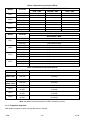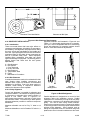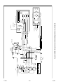
1
Transport Air Conditioning
OPERATION & SERVICE
for
SPLIT SYSTEMS
Generation 4 & 5
T--299 Rev C Change 06/10
OPERATION AND
SERVICE MANUAL
BUS
AIR CONDITIONING
EQUIPMENT
SPLIT--SYSTEMS
Generation 4 & 5
SAFETY SUMMARY
GENERAL SAFETY NOTICES
The following general safety notices supplement the specific warnings and cautions appearing elsewhere in this
manual. They are recommended precautions that must be understood and applied during operation, service, and
maintenance of the equipment covered herein. The general safety notices are presented in the following three
sections labeled: First Aid, Operating Precautions and Maintenance Precautions. A listing of the specific warnings and
cautions appearing elsewhere in the manual follows the general safety notices.
FIRST AID
An injury, no matter how slight, should never go unattended. Always obtain first aid or medical attention immediately.
OPERATING PRECAUTIONS
Always wear protective eye wear (safety glasses or goggles).
Keep hands, clothing and tools clear of the evaporator and condenser fans.
No work should be performed on the system unless battery power is disconnected.
Always work in pairs. Never work on the equipment alone.
In case of severe vibration or unusual noise, stop the system and investigate.
MAINTENANCE PRECAUTIONS
Familiarize yourself with the proper operation of any service equipment you will be using (voltmeter, amp probe,
manifold gauges, etc.). Always read the owner’s manual that is enclosed with the equipment
Always follow the manufacturers instructions for your recovery/recycling equipment. Failure to do so could cause
personal injury or damage to your equipment. Never perform any maintenance or service on your equipment before
consulting with authorized service personnel. Always unplug unit before attempting any maintenance. Removing
internal fittings and filters can release pressurized refrigerant. Slowly release pressure and always wear appropriate
safety wear.
Avoid breathing any refrigerant vapor, lubricant vapor, or mist. Exposure to these, particularly PAG oil mist, may irritate
your eyes, nose, or throat.
Always use a DOT (Department of Transportation) approved cylinder for storing used and recycled refrigerant.
Approved cylinders will be stamped DOT 4BW or DOT 4BA. Carrier recommends a MACS (Mobile Air Conditioning
Society) certification in Recovery/Recycling to gain more information on handling and using refrigerants.
Never attempt to apply heat or open flame to a refrigerant cylinder. High temperatures can raise the cylinder pressure
to dangerous levels. Carrier recommends using a heat blanket to increase the internal temperature of the refrigerant
cylinder, greatly increasing the transfer of refrigerant to the bus air conditioning system.
Never use compressed air (shop--air) to leak--test or pressure test a R134a system. Under certain conditions,
pressurized mixtures of R134a and air can be combustible. In addition, shop air will inject moisture into the system.
Always use mineral oil to lubricate “O” Rings, hoses, and fittings on R134a systems. PAG oils will absorb moisture and
become very acidic and corrosive. Mineral oil will not absorb moisture and thus prevent corrosion. Always wear gloves
when working with PAG and Ester lubricants to prevent irritation to your skin. R134a lubricants can also damage
vehicles paint, plastic parts, engine drive belts and coolant hoses.
Beware of unannounced starting of the evaporator and condenser fans. Do not remove the evaporator cover or
condenser fan guards without disconnecting the vehicle battery cable.
Be sure power is turned off before working on motors, controllers, and electrical control switches. Tag system controls
and vehicle battery to prevent accidental energizing of the system.
Do not bypass any electrical safety devices, e.g. bridging an overload, or using any sort of jumper wires. Problems with
the system should be diagnosed, and any necessary repairs performed, by qualified service personnel.
When performing any arc welding on the vehicle, disconnect the vehicle battery.
In case of electrical fire, extinguish with CO2 (never use water). Disconnect vehicle battery power if possible.
01/08
Safety - 1
T-299
SPECIFIC WARNINGS
WARNING
Beware of unannounced starting of the evaporator and condenser fans. The unit may cycle the fans
and compressor unexpectedly as control requirements dictate.
WARNING
Be sure to observe warnings listed in the safety summary in the front of this manual before performing maintenance on the air conditioning system
WARNING
Never use air for leak testing. It has been determined that pressurized, air-rich mixtures of refrigerants and air can undergo combustion when exposed to an ignition source.
WARNING
Do not use a nitrogen cylinder without a pressure regulator. Do not use oxygen in or near a
refrigeration system or as an explosion may occur.
WARNING
To prevent trapping liquid refrigerant in the manifold gauge set be sure set is brought to suction
pressure before disconnecting.
WARNING
There may be liquid refrigerant trapped behind the block valve. Slowly loosen the fitting
and avoid contact with exposed skin or eyes.
WARNING
The filter-drier may contain liquid refrigerant. Slowly open the fitting nuts and avoid contact
with exposed skin or eyes.
CAUTION
Unless there was a catastrophic failure, such as a blown or ruptured refrigerant hose, additional oil
may not be needed.
CAUTION
Use only the exact oil specified by the compressor manufacturer. Use of oil other than that specified
will void the compressor warranty.
T-299
Safety - 2
01/08
TABLE OF CONTENTS
PARAGRAPH NUMBER
Page
SAFETY SUMMARY . . . . . . . . . . . . . . . . . . . . . . . . . . . . . . . . . . . . . . . . . . . . . . . . . . . . . . . . . . . . . . . . . . Safety --i
SPECIFIC WARNINGS . . . . . . . . . . . . . . . . . . . . . . . . . . . . . . . . . . . . . . . . . . . . . . . . . . . . . . . . . . . . . Safety --ii
DESCRIPTION . . . . . . . . . . . . . . . . . . . . . . . . . . . . . . . . . . . . . . . . . . . . . . . . . . . . . . . . . . . . . . . . . . . . . . . . . . . . . . .
1-1
1.1
1.2
1.3
INTRODUCTION . . . . . . . . . . . . . . . . . . . . . . . . . . . . . . . . . . . . . . . . . . . . . . . . . . . . . . . . . . . . . . . . . . . . .
WHAT IS AIR CONDITIONING . . . . . . . . . . . . . . . . . . . . . . . . . . . . . . . . . . . . . . . . . . . . . . . . . . . . . . . . .
MODEL AND SERIAL NUMBER TAGS . . . . . . . . . . . . . . . . . . . . . . . . . . . . . . . . . . . . . . . . . . . . . . . . . .
1.3.1 PID Data Tag (Decal) . . . . . . . . . . . . . . . . . . . . . . . . . . . . . . . . . . . . . . . . . . . . . . . . . . . . . . . . . . . . . .
1-1
1-1
1-1
1-1
1.4
1.5
1.6
SYSTEM REQUIREMENTS LABEL . . . . . . . . . . . . . . . . . . . . . . . . . . . . . . . . . . . . . . . . . . . . . . . . . . . . .
SYSTEM DESIGNATIONS . . . . . . . . . . . . . . . . . . . . . . . . . . . . . . . . . . . . . . . . . . . . . . . . . . . . . . . . . . . . .
SYSTEM COMPONENTS . . . . . . . . . . . . . . . . . . . . . . . . . . . . . . . . . . . . . . . . . . . . . . . . . . . . . . . . . . . . .
1-4
1-4
1-5
1.7
1.8
REFRIGERATION SYSTEM COMPONENT SPECIFICATIONS . . . . . . . . . . . . . . . . . . . . . . . . . . . . .
COOLING CYCLE . . . . . . . . . . . . . . . . . . . . . . . . . . . . . . . . . . . . . . . . . . . . . . . . . . . . . . . . . . . . . . . . . . . .
1-6
1-7
1.9
HEATING CYCLE (If Applicable) . . . . . . . . . . . . . . . . . . . . . . . . . . . . . . . . . . . . . . . . . . . . . . . . . . . . . . . .
1-9
OPERATION . . . . . . . . . . . . . . . . . . . . . . . . . . . . . . . . . . . . . . . . . . . . . . . . . . . . . . . . . . . . . . . . . . . . . . . . . . . . . . . . .
2.1 OPERATING INSTRUCTIONS . . . . . . . . . . . . . . . . . . . . . . . . . . . . . . . . . . . . . . . . . . . . . . . . . . . . . . . . .
2.2 MANUAL CONTROLS . . . . . . . . . . . . . . . . . . . . . . . . . . . . . . . . . . . . . . . . . . . . . . . . . . . . . . . . . . . . . . . .
2-1
2-1
2-1
2.2.1 Driver’s Control Panel . . . . . . . . . . . . . . . . . . . . . . . . . . . . . . . . . . . . . . . . . . . . . . . . . . . . . . . . . . . . . .
2-1
2.2.2 Fan Speed Switch (three speed or variable) . . . . . . . . . . . . . . . . . . . . . . . . . . . . . . . . . . . . . . . . . . .
2.2.3 Thermostat Control . . . . . . . . . . . . . . . . . . . . . . . . . . . . . . . . . . . . . . . . . . . . . . . . . . . . . . . . . . . . . . . .
2.2.4 Electrical Control Panel . . . . . . . . . . . . . . . . . . . . . . . . . . . . . . . . . . . . . . . . . . . . . . . . . . . . . . . . . . . .
2-1
2-1
2-1
FLORIDA CONTROL (TEMPCON) . . . . . . . . . . . . . . . . . . . . . . . . . . . . . . . . . . . . . . . . . . . . . . . . . . . . . .
2.3.1 ON/OFF Function . . . . . . . . . . . . . . . . . . . . . . . . . . . . . . . . . . . . . . . . . . . . . . . . . . . . . . . . . . . . . . . . .
2.3.2 Fan Speed Switch -- 3 Speed . . . . . . . . . . . . . . . . . . . . . . . . . . . . . . . . . . . . . . . . . . . . . . . . . . . . . . .
2.3.3 Adjusting Set Point (Interior Temperature Adjustment) . . . . . . . . . . . . . . . . . . . . . . . . . . . . . . . . . .
2-2
2-2
2-2
2-2
2.4 IN--LINE FUSE (FLORIDA CONTROL) . . . . . . . . . . . . . . . . . . . . . . . . . . . . . . . . . . . . . . . . . . . . . . . . . .
2.5 TOTAL CONTROL . . . . . . . . . . . . . . . . . . . . . . . . . . . . . . . . . . . . . . . . . . . . . . . . . . . . . . . . . . . . . . . . . . . .
2.5.1 Total Control Operation . . . . . . . . . . . . . . . . . . . . . . . . . . . . . . . . . . . . . . . . . . . . . . . . . . . . . . . . . . . . . . . .
2-2
2-3
2-3
2.6
2.7
GEN 4 -- WITH TOTAL CONTROL, UNIT OPERATING INSTRUCTIONS . . . . . . . . . . . . . . . . . . . .
PRE--TRIP INSPECTION . . . . . . . . . . . . . . . . . . . . . . . . . . . . . . . . . . . . . . . . . . . . . . . . . . . . . . . . . . . . . .
2-4
2-5
2.8
SEQUENCE OF OPERATION . . . . . . . . . . . . . . . . . . . . . . . . . . . . . . . . . . . . . . . . . . . . . . . . . . . . . . . . . .
2-5
2.3
2.8.1
2.8.2
2.8.3
2.8.4
Three Position Switch Operation . . . . . . . . . . . . . . . . . . . . . . . . . . . . . . . . . . . . . . . . . . . . . . . . . . . .
Variable Speed Control Operation . . . . . . . . . . . . . . . . . . . . . . . . . . . . . . . . . . . . . . . . . . . . . . . . . . .
Total Control -- Gen 5 Operation . . . . . . . . . . . . . . . . . . . . . . . . . . . . . . . . . . . . . . . . . . . . . . . . . . . . .
Total Control -- Gen 4 Operation . . . . . . . . . . . . . . . . . . . . . . . . . . . . . . . . . . . . . . . . . . . . . . . . . . . . .
2-5
2-5
2-5
2-6
2.8.5 Heat Option . . . . . . . . . . . . . . . . . . . . . . . . . . . . . . . . . . . . . . . . . . . . . . . . . . . . . . . . . . . . . . . . . . . . . .
TROUBLESHOOTING . . . . . . . . . . . . . . . . . . . . . . . . . . . . . . . . . . . . . . . . . . . . . . . . . . . . . . . . . . . . . . . . . . . . . . . . .
3.1 INSUFFICIENT OR NO COOLING . . . . . . . . . . . . . . . . . . . . . . . . . . . . . . . . . . . . . . . . . . . . . . . . . . . . . .
2-6
3-1
3-1
3.1.1 Preliminary Checks . . . . . . . . . . . . . . . . . . . . . . . . . . . . . . . . . . . . . . . . . . . . . . . . . . . . . . . . . . . . . . . .
3.1.2 Checking System Air Output . . . . . . . . . . . . . . . . . . . . . . . . . . . . . . . . . . . . . . . . . . . . . . . . . . . . . . . .
3.1.3 Check The Sight Glass For Bubbles . . . . . . . . . . . . . . . . . . . . . . . . . . . . . . . . . . . . . . . . . . . . . . . . .
3-1
3-1
3-1
3.1.4 Compressor Amp Draw . . . . . . . . . . . . . . . . . . . . . . . . . . . . . . . . . . . . . . . . . . . . . . . . . . . . . . . . . . . .
3.2 SYSTEM WILL NOT COOL . . . . . . . . . . . . . . . . . . . . . . . . . . . . . . . . . . . . . . . . . . . . . . . . . . . . . . . . . . . .
3.3 SYSTEM RUNS BUT HAS INSUFFICIENT COOLING . . . . . . . . . . . . . . . . . . . . . . . . . . . . . . . . . . . . .
3-2
3-3
3-3
01/08
i
T--299
TABLE OF CONTENTS -- Continued:
SERVICE . . . . . . . . . . . . . . . . . . . . . . . . . . . . . . . . . . . . . . . . . . . . . . . . . . . . . . . . . . . . . . . . . . . . . . . . . . . . . . . . . . . .
4-1
4.1
4.2
4.3
PREVENTATIVE MAINTENANCE SCHEDULE . . . . . . . . . . . . . . . . . . . . . . . . . . . . . . . . . . . . . . . . . . .
MAINTENANCE PROCEDURES . . . . . . . . . . . . . . . . . . . . . . . . . . . . . . . . . . . . . . . . . . . . . . . . . . . . . . .
INSTALLING MANIFOLD GAUGES . . . . . . . . . . . . . . . . . . . . . . . . . . . . . . . . . . . . . . . . . . . . . . . . . . . . .
4-1
4-2
4-2
4.4
4.5
4.6
REFRIGERANT RECOVERY . . . . . . . . . . . . . . . . . . . . . . . . . . . . . . . . . . . . . . . . . . . . . . . . . . . . . . . . . .
REFRIGERANT LEAK CHECKING . . . . . . . . . . . . . . . . . . . . . . . . . . . . . . . . . . . . . . . . . . . . . . . . . . . . .
EVACUATION AND DEHYDRATION . . . . . . . . . . . . . . . . . . . . . . . . . . . . . . . . . . . . . . . . . . . . . . . . . . . .
4.6.1 General . . . . . . . . . . . . . . . . . . . . . . . . . . . . . . . . . . . . . . . . . . . . . . . . . . . . . . . . . . . . . . . . . . . . . . . . . .
4-4
4-4
4-4
4-4
4.6.2 Preparation . . . . . . . . . . . . . . . . . . . . . . . . . . . . . . . . . . . . . . . . . . . . . . . . . . . . . . . . . . . . . . . . . . . . . . .
4.6.3 Procedure For Evacuation and Dehydrating System (Triple Evacuation) . . . . . . . . . . . . . . . . . .
4.7 PROCEDURE FOR EVACUATION AND DEHYDRATING SYSTEM (ONE TIME EVACUATION)
4-4
4-5
4-5
4.8
ADDING REFRIGERANT TO A SYSTEM . . . . . . . . . . . . . . . . . . . . . . . . . . . . . . . . . . . . . . . . . . . . . . . .
4.8.1 Checking Refrigerant Charge . . . . . . . . . . . . . . . . . . . . . . . . . . . . . . . . . . . . . . . . . . . . . . . . . . . . . . .
4-5
4-5
4.8.2 Adding Full Charge . . . . . . . . . . . . . . . . . . . . . . . . . . . . . . . . . . . . . . . . . . . . . . . . . . . . . . . . . . . . . . . .
4-5
4.8.3 Adding Partial Charge . . . . . . . . . . . . . . . . . . . . . . . . . . . . . . . . . . . . . . . . . . . . . . . . . . . . . . . . . . . . .
4.9 COMPRESSOR(S) . . . . . . . . . . . . . . . . . . . . . . . . . . . . . . . . . . . . . . . . . . . . . . . . . . . . . . . . . . . . . . . . . . .
4.9.1 . Evaporator Tie-In . . . . . . . . . . . . . . . . . . . . . . . . . . . . . . . . . . . . . . . . . . . . . . . . . . . . . . . . . . . . . . . . . .
4-5
4-5
4-7
4.10 TORQUE SPECIFICATIONS -- REFRIGERANT FITTINGS . . . . . . . . . . . . . . . . . . . . . . . . . . . . . . . .
4-9
4.11 TORQUE SPECIFICATIONS -- BOLTS . . . . . . . . . . . . . . . . . . . . . . . . . . . . . . . . . . . . . . . . . . . . . . . . . .
4.11.1 Electrical Control Panel - Torque Values . . . . . . . . . . . . . . . . . . . . . . . . . . . . . . . . . . . . . . . . . . . . . .
4.12 DRIVE BELT INSTALLATION . . . . . . . . . . . . . . . . . . . . . . . . . . . . . . . . . . . . . . . . . . . . . . . . . . . . . . . . . .
4-9
4-9
4-10
4.12.1
4.12.2
4.12.3
4.12.4
Introduction . . . . . . . . . . . . . . . . . . . . . . . . . . . . . . . . . . . . . . . . . . . . . . . . . . . . . . . . . . . . . . . . . . . . . .
Belt Clearance . . . . . . . . . . . . . . . . . . . . . . . . . . . . . . . . . . . . . . . . . . . . . . . . . . . . . . . . . . . . . . . . . . . .
Pulley Alignment . . . . . . . . . . . . . . . . . . . . . . . . . . . . . . . . . . . . . . . . . . . . . . . . . . . . . . . . . . . . . . . . . .
Drive Belt Tension Guidelines . . . . . . . . . . . . . . . . . . . . . . . . . . . . . . . . . . . . . . . . . . . . . . . . . . . . . . .
4-10
4-10
4-10
4-11
4.12.5 Measuring Methods for Belt Tension . . . . . . . . . . . . . . . . . . . . . . . . . . . . . . . . . . . . . . . . . . . . . . . . .
4.13 RETURN AIR FILTER . . . . . . . . . . . . . . . . . . . . . . . . . . . . . . . . . . . . . . . . . . . . . . . . . . . . . . . . . . . . . . . . .
4.13.1 GEN 4 (EXCEL) Series . . . . . . . . . . . . . . . . . . . . . . . . . . . . . . . . . . . . . . . . . . . . . . . . . . . . . . . . . . . .
4-11
4-11
4-11
4.13.2 GEN 5 Series . . . . . . . . . . . . . . . . . . . . . . . . . . . . . . . . . . . . . . . . . . . . . . . . . . . . . . . . . . . . . . . . . . . . .
4.14 EVAPORATOR BLOWER AND/OR MOTOR ASSEMBLY . . . . . . . . . . . . . . . . . . . . . . . . . . . . . . . . . .
4-12
4-12
4.14.1 GEN 4 Series . . . . . . . . . . . . . . . . . . . . . . . . . . . . . . . . . . . . . . . . . . . . . . . . . . . . . . . . . . . . . . . . . . . . .
4-12
4.14.2 GEN 5 Series . . . . . . . . . . . . . . . . . . . . . . . . . . . . . . . . . . . . . . . . . . . . . . . . . . . . . . . . . . . . . . . . . . . . .
4.15 RESISTORS . . . . . . . . . . . . . . . . . . . . . . . . . . . . . . . . . . . . . . . . . . . . . . . . . . . . . . . . . . . . . . . . . . . . . . . . .
4.15.1 GEN 4 Series (Excel) . . . . . . . . . . . . . . . . . . . . . . . . . . . . . . . . . . . . . . . . . . . . . . . . . . . . . . . . . . . . . .
4.15.2 GEN 5 Series . . . . . . . . . . . . . . . . . . . . . . . . . . . . . . . . . . . . . . . . . . . . . . . . . . . . . . . . . . . . . . . . . . . . .
4-12
4-12
4-12
4-12
4.16 CONDENSER FAN ASSEMBLY . . . . . . . . . . . . . . . . . . . . . . . . . . . . . . . . . . . . . . . . . . . . . . . . . . . . . . . .
4.17 REPLACING THERMOSTATIC BLOCK VALVE . . . . . . . . . . . . . . . . . . . . . . . . . . . . . . . . . . . . . . . . . . .
4.18 CHECKING AND REPLACING HIGH PRESSURE SWITCH . . . . . . . . . . . . . . . . . . . . . . . . . . . . . . .
4-12
4-13
4-13
4.18.1 Replacing High or Low Pressure Switch . . . . . . . . . . . . . . . . . . . . . . . . . . . . . . . . . . . . . . . . . . . . .
4.18.2 Checking High Pressure Switch . . . . . . . . . . . . . . . . . . . . . . . . . . . . . . . . . . . . . . . . . . . . . . . . . . . . .
4.19 MOISTURE INDICATOR (SYSTEM) . . . . . . . . . . . . . . . . . . . . . . . . . . . . . . . . . . . . . . . . . . . . . . . . . . . .
4-13
4-13
4-14
4.20 FILTER-DRIER & RECEIVER--DRIER . . . . . . . . . . . . . . . . . . . . . . . . . . . . . . . . . . . . . . . . . . . . . . . . . . .
ELECTRICAL SCHEMATIC DIAGRAMS . . . . . . . . . . . . . . . . . . . . . . . . . . . . . . . . . . . . . . . . . . . . . . . . . . . . . . . . .
4-14
5-1
5.1
T--299
INTRODUCTION . . . . . . . . . . . . . . . . . . . . . . . . . . . . . . . . . . . . . . . . . . . . . . . . . . . . . . . . . . . . . . . . . . . . .
ii
5-1
01/08
LIST OF ILLUSTRATIONS
Figure
Page
Figure 1-1 Condenser Model CM2/3 - Serial Number Location . . . . . . . . . . . . . . . . . . . . . . . . . . . . . . . . . . . . . .
Figure 1-2 GEN 4 Evaporator Model - Serial Number Location . . . . . . . . . . . . . . . . . . . . . . . . . . . . . . . . . . . . . .
Figure 1-3 GEN 5 Evaporator Model (All) - Serial Number Location . . . . . . . . . . . . . . . . . . . . . . . . . . . . . . . . . .
Figure 1-4 GEN 4, IW-2 & IW-7 - Serial Number Location . . . . . . . . . . . . . . . . . . . . . . . . . . . . . . . . . . . . . . . . . .
Figure 1-5 GEN 4, IW-1 - Serial Number Location . . . . . . . . . . . . . . . . . . . . . . . . . . . . . . . . . . . . . . . . . . . . . . . . .
Figure 1-6 CM-7/11 Rooftop Condensers (No Longer Offered) - Serial Number Location . . . . . . . . . . . . . . .
Figure 1-7 KR-2/KR-3 Rooftop Condensers - Serial Number/PID Location . . . . . . . . . . . . . . . . . . . . . . . . . . . .
Figure 1-8 System Requirements Label . . . . . . . . . . . . . . . . . . . . . . . . . . . . . . . . . . . . . . . . . . . . . . . . . . . . . . . . .
Figure 1-9 Component Location Diagram . . . . . . . . . . . . . . . . . . . . . . . . . . . . . . . . . . . . . . . . . . . . . . . . . . . . . . . .
Figure 1-10 Air Conditioning Refrigerant Flow Diagram -- Small Split System . . . . . . . . . . . . . . . . . . . . . . . . .
Figure 1-11 Heating System Flow Diagram (Typical) . . . . . . . . . . . . . . . . . . . . . . . . . . . . . . . . . . . . . . . . . . . . . .
Figure 2-1 Drivers Control Panel . . . . . . . . . . . . . . . . . . . . . . . . . . . . . . . . . . . . . . . . . . . . . . . . . . . . . . . . . . . . . . . .
Figure 2-2 Electrical Panel (Typical) . . . . . . . . . . . . . . . . . . . . . . . . . . . . . . . . . . . . . . . . . . . . . . . . . . . . . . . . . . . . .
Figure 2-3 Switch Assembly (TEMPCON) . . . . . . . . . . . . . . . . . . . . . . . . . . . . . . . . . . . . . . . . . . . . . . . . . . . . . . .
Figure 2-4 In--Line Fuse & Holder (3 Amp) . . . . . . . . . . . . . . . . . . . . . . . . . . . . . . . . . . . . . . . . . . . . . . . . . . . . . . .
Figure 2-5 Total Control Key Pad/Display . . . . . . . . . . . . . . . . . . . . . . . . . . . . . . . . . . . . . . . . . . . . . . . . . . . . . . . .
Figure 2-6 Null Band . . . . . . . . . . . . . . . . . . . . . . . . . . . . . . . . . . . . . . . . . . . . . . . . . . . . . . . . . . . . . . . . . . . . . . . . . .
Figure 2-7 Total Control Electrical Control Panel (Typical) . . . . . . . . . . . . . . . . . . . . . . . . . . . . . . . . . . . . . . . . . .
Figure 4-1 Manifold Gauge Set . . . . . . . . . . . . . . . . . . . . . . . . . . . . . . . . . . . . . . . . . . . . . . . . . . . . . . . . . . . . . . . . .
Figure 4-2 Refrigerant Service Connections (Split Systems) . . . . . . . . . . . . . . . . . . . . . . . . . . . . . . . . . . . . . . . .
Figure 4-1 Micro-Channel Style Condenser Assembly . . . . . . . . . . . . . . . . . . . . . . . . . . . . . . . . . . . . . . . . . . . . .
Figure 4-3 Metric Bolt Markings . . . . . . . . . . . . . . . . . . . . . . . . . . . . . . . . . . . . . . . . . . . . . . . . . . . . . . . . . . . . . . . .
Figure 4-4 U.S. Bolt Markings . . . . . . . . . . . . . . . . . . . . . . . . . . . . . . . . . . . . . . . . . . . . . . . . . . . . . . . . . . . . . . . . . .
Figure 4-5 Belt Clearance Requirements . . . . . . . . . . . . . . . . . . . . . . . . . . . . . . . . . . . . . . . . . . . . . . . . . . . . . . . .
Figure 4-6 Belt Misalignment . . . . . . . . . . . . . . . . . . . . . . . . . . . . . . . . . . . . . . . . . . . . . . . . . . . . . . . . . . . . . . . . . . .
Figure 4-7 Straight--Edge Application . . . . . . . . . . . . . . . . . . . . . . . . . . . . . . . . . . . . . . . . . . . . . . . . . . . . . . . . . . . .
Figure 4-8 GEN 4 Series Resistor Assembly . . . . . . . . . . . . . . . . . . . . . . . . . . . . . . . . . . . . . . . . . . . . . . . . . . . . .
Figure 4-9. Checking High Pressure Switch . . . . . . . . . . . . . . . . . . . . . . . . . . . . . . . . . . . . . . . . . . . . . . . . . . . . . .
Figure 4-10 Filter Drier Removal . . . . . . . . . . . . . . . . . . . . . . . . . . . . . . . . . . . . . . . . . . . . . . . . . . . . . . . . . . . . . . . .
Figure 5-1 Electrical Schematic Diagram -- Symbols . . . . . . . . . . . . . . . . . . . . . . . . . . . . . . . . . . . . . . . . . . . . . . .
Figure 5-2 Legend -- Electrical Schematic Diagrams . . . . . . . . . . . . . . . . . . . . . . . . . . . . . . . . . . . . . . . . . . . . . . .
Figure 5-3 GEN 4 System Schematic -- EM--1 With CM--2/3 . . . . . . . . . . . . . . . . . . . . . . . . . . . . . . . . . . . . . . . .
Figure 5-4 GEN 4 System Schematic -- EM--1 With CM--2/3 -- Tie--In . . . . . . . . . . . . . . . . . . . . . . . . . . . . . . . .
Figure 5-5 GEN 4 System Schematic -- EM--3 With (2) CM--3 Condensers & (2) Compressors . . . . . . . . . .
Figure 5-6 GEN 5 Evaporator (With Variable Speed Control) Schematic . . . . . . . . . . . . . . . . . . . . . . . . . . . . .
Figure 5-7 GEN 5 System Schematic With Total Control . . . . . . . . . . . . . . . . . . . . . . . . . . . . . . . . . . . . . . . . . . .
Figure 5-8 GEN 4 EM--3 With (2) CM--3 With Total Control -- System Schematic . . . . . . . . . . . . . . . . . . . . . .
Figure 5-9 GEN 4 Series With Total Control . . . . . . . . . . . . . . . . . . . . . . . . . . . . . . . . . . . . . . . . . . . . . . . . . . . . . .
01/08
iii
1-2
1-2
1-2
1-3
1-3
1-3
1-4
1-4
1-5
1-8
1-9
2-1
2-1
2-2
2-2
2-3
2-4
2-4
4-2
4-3
4-7
4-9
4-9
4-10
4-10
4-11
4-12
4-13
4-14
5-1
5-2
5-3
5-4
5-5
5-6
5-7
5-8
5-9
T--299
LIST OF TABLES
Table 1-1 Additional Support Manuals . . . . . . . . . . . . . . . . . . . . . . . . . . . . . . . . . . . . . . . . . . . . . . . . . . . . . . . . . . . .
Table 3-1 Evaporator Current Draw (GEN 4) . . . . . . . . . . . . . . . . . . . . . . . . . . . . . . . . . . . . . . . . . . . . . . . . . . . . . .
Table 3-2 Evaporator Current Draw (GEN 5) . . . . . . . . . . . . . . . . . . . . . . . . . . . . . . . . . . . . . . . . . . . . . . . . . . . . . .
Table 3-3 Condenser Current Draw (GEN 5) . . . . . . . . . . . . . . . . . . . . . . . . . . . . . . . . . . . . . . . . . . . . . . . . . . . . . .
Table 3-4 GENERAL SYSTEM TROUBLESHOOTING PROCEDURES . . . . . . . . . . . . . . . . . . . . . . . . . . . . . . .
Table 3-4 GENERAL SYSTEM TROUBLESHOOTING PROCEDURES -- Continued . . . . . . . . . . . . . . . . . . .
Table 4-1 Split System Refrigerant And Oil Charging Table -- Thru GEN 4 . . . . . . . . . . . . . . . . . . . . . . . . . . . . .
1-1
3-1
3-2
3-2
3-3
3-4
4-6
Table 4-2 SPLIT SYSTEM REFRIGERANT AND OIL CHARGING TABLE (GEN--5) . . . . . . . . . . . . . . . . . . . .
Table 4-3 SPLIT--SYSTEM GEN--5 WITH MICRO--CHANNEL CONDENSER . . . . . . . . . . . . . . . . . . . . . . . . .
Table 4-4 Compressor Oil Type & Part Numbers . . . . . . . . . . . . . . . . . . . . . . . . . . . . . . . . . . . . . . . . . . . . . . . . . . .
Table 4-5 CARRIER TRANSPORT AIR CONDITIONING SYSTEM PERFORMANCE CHART . . . . . . . . . . .
Table 4-6 STANDARD TORQUE REQUIREMENTS . . . . . . . . . . . . . . . . . . . . . . . . . . . . . . . . . . . . . . . . . . . . . . . .
Table 4-7 Metric Torque Specs . . . . . . . . . . . . . . . . . . . . . . . . . . . . . . . . . . . . . . . . . . . . . . . . . . . . . . . . . . . . . . . . . .
Table 4-8 U.S. Torque Specs . . . . . . . . . . . . . . . . . . . . . . . . . . . . . . . . . . . . . . . . . . . . . . . . . . . . . . . . . . . . . . . . . . . .
Table 4-9 Belt Tension Guide . . . . . . . . . . . . . . . . . . . . . . . . . . . . . . . . . . . . . . . . . . . . . . . . . . . . . . . . . . . . . . . . . . . .
Table 4-10 R-134a Temperature - Pressure Chart . . . . . . . . . . . . . . . . . . . . . . . . . . . . . . . . . . . . . . . . . . . . . . . . . .
4-6
4-6
4-7
4-8
4-9
4-9
4-9
4-11
4-15
T--299
iv
01/08
SECTION 1
DESCRIPTION
condenser data tag locations, Figure 1-2 for GEN 4
evaporator data tag location, Figure 1-3 for GEN 5
evaporator data tag locations, Figure 1-4 & Figure 1-5
for In--Wall data tag locations, Figure 1-7 for KR--2 &
KR--3 PID locations and Figure 1-6 for the CM--7 &
CM--11 rooftop condensers data tag location. The
CM--7 and CM--11 rooftop condensers are no longer
available from Carrier TAC.
1.1 INTRODUCTION
This manual contains Operating, Service, and
Maintenance Instructions for Gen 4 and Gen 5 Split
System Air Conditioning and Heating equipment
furnished by Carrier Transport Air Conditioning.
Additional support manuals are listed in Table 1-1.
A Split System normally includes an Evaporator(s), a
Condenser(s) a Compressor(s) and interconnecting
refrigerant hoses, fittings, and electrical harnesses and
controls. A listing of the evaporator and condenser
models, along with specific data for each, is provided in
the component data that follows.
Specific systems may vary, this manual does not cover
all combinations, variations, and applications, it does
set up standards from which processes can be
measured. Contact Carrier Transport Air Conditioning
Technical Service Hot--Line for additional assistance
(800--450--2211).
NOTE
The EM--9 evaporator data tag is located on the
side of the evaporator assembly, not between
the blower assemblies (See Figure 1-2).
Knowing these locations and the information on the data
tags will aid you in identifying the correct service
procedures.
1.3.1 PID Data Tag (Decal)
All KR2, KR3 & KR4 Rooftop Condensers have PID
Decals instead of the standard Model/Serail tag. These
tags will list the following:
1.2 WHAT IS AIR CONDITIONING
Air
Conditioning
is
the
cooling,
heating,
dehumidification, and filtration of the air located within
the passenger compartment of a vehicle.
a. System Model No. (Example -- 68KR4--101--2)
b. Serial No.
1.3 MODEL AND SERIAL NUMBER TAGS
c. P.I.D. (Example -- KR4C00032)
In order to identify the air conditioning components you
have, you will need to know the model number and serial
number. All Carrier Transport Air Conditioning
evaporators, condensers and compressors have a
model/serial number tag or PID decal located on the
assembly. See Figure 1-1 for all skirt mounted
d. Refrigerant (Example -- R134a)
e. Voltage (Example -- 13.5 VDC)
f. Amps (Example -- 25A)
g. Unit Weight (Example -- 186 lbs.)
Table 1-1 Additional Support Manuals
01/08
MANUAL NUMBER
EQUIPMENT COVERED
TYPE OF MANUAL
T--299PL
Split Systems
Parts List
T--311
Split Systems
Installation Procedures
62--50455
Basic Refrigeration
Service Training
62--50468
Transport Refrigeration
Service Training
62--03213
Service Tools
Service Tools
1--1
T-299
Figure 1-1 Condenser Model CM2/3 - Serial Number Location
EM-9 Location
Figure 1-2 GEN 4 Evaporator Model - Serial Number Location
Figure 1-3 GEN 5 Evaporator Model (All) - Serial Number Location
T-299
1--2
01/08
2
5
Figure 1-4 GEN 4, IW-2 & IW-7 - Serial Number Location
Figure 1-5 GEN 4, IW-1 - Serial Number Location
Obsolete Tag
Figure 1-6 CM-7/11 Rooftop Condensers (No Longer Offered) - Serial Number Location
01/08
1--3
T-299
Figure 1-7 KR-2/KR-3 Rooftop Condensers - Serial Number/PID Location
01- 22- 07
Figure 1-8 System Requirements Label
1.4 SYSTEM REQUIREMENTS LABEL
NOTE
You may encounter installations where the
The system requirements label is conveniently located
OEM radiator style condenser is used as the
within the vehicle’s engine compartment. This label,
Tie--In condenser. Call Carrier Transport Air
when properly completed by the installer, will give the
Conditioning Technical Service Hot--Line
servicing technician the refrigerant and oil charge(s),
(800--450--2211) for assistance, as this is not a
evaporator(s), condenser(s), and compressor(s) serial
numbers, the drive belt(s) number, mount kit number,
recommended Carrier Transport Air Cond-the date of installation and the installer (See Figure 1-8).
itioning application.
Max System -- A Carrier system installed along with an
existing OEM system. The systems operate
independent of each other.
Stand--Alone (Standard) System -- All Carrier
components installed on a vehicle. These can be either
single or dual compressor systems.
1.5 SYSTEM DESIGNATIONS
Tie--In System -- Is a Carrier evaporator and condenser
connected to an existing OEM compressor and dash
evaporator. The OEM radiator condenser is normally
removed.
T-299
1--4
01/08
IW (In--Wall) System -- A Carrier evaporator installed in
the front and/or rear of the vehicle. This type evaporator
is installed between the inside & outside walls of the
vehicle.
when activated, signals the Electro--Magnetic Clutch to
engage/disengage. The return air thermostat is
normally located in the drivers control panel while the
return air thermister is normally located in the
evaporator assembly.
1.6 SYSTEM COMPONENTS
Electro--Magnetic clutch -- The Electro--Magnetic
clutch controls the operation of the compressor. When
engaged, the compressor circulates refrigerant and
provides cooling (See Figure 1-9).
Return Air Thermostat/Sensor -- The system may be
supplied with a thermostat or thermistor Both of these
devices are temperature sensitive components which
8
9
6
7
5
12
4
10
5
3
2
11
1
1
2
3
4
5
6
Compressor
Electro--Magnetic Clutch
Discharge Line
Condenser
Filter--Dryer or Receiver--Drier
Liquid Line
7
8
9
10
11
12
Evaporator
Block Valve (TXV)
Freezestat--(Coil freeze--up thermostat)
Suction Line
Suction Access Valve
Discharge Access Valve
Figure 1-9 Component Location Diagram
Compressor -- The compressor is a belt driven,
Filter--Dryer -- The filter--dryer removes moisture and
high--pressure pump, which circulates the refrigerant
particulate matter from the refrigerant.
through the evaporator and condenser . The operation
Receiver--Dryer -- The receiver--dryer removes
of the compressor is controlled by the Electro--Magnetic
moisture and particulate matter from the refrigerant.
clutch.
The receiver--drier also stores a small amount of liquid
Condenser -- The condenser is normally located in the
refrigerant.
skirt or on the roof of the vehicle. Its primary function is to
reject heat, which was transferred to the refrigerant by
the evaporator from the passenger compartment of the
vehicle.
01/08
1--5
T-299
Expansion/Block Valve -- Meters the refrigerant flow
into the evaporator coil. The majority of the Gen 4
(Excel) and all Gen 5 systems use a nonadjustable
block valve with an 8° F superheat setting, which is
preset at the factory. If you feel there is a problem with
the block valve, do not attempt to adjust the valve,
replace it.
c.
GEN 4 Series Freeze--Up Thermostat: Cut--out at 26° F,
±1.5° F. Cut--in at 34° F, ±1.5° F. Pre--set at factory
(Adjustable). Turn counterclockwise to end -- then 1/4
turn clockwise for original factory setting.
GEN 5 Series Freeze--Up Thermostat: Cut--out at 30.5°
F, ±1.5° F. Cut--in at 45° F, ±1.5° F. Pre--set at the
factory (Non--adjustable).
NOTE
In the event you encounter a Gen 1, Gen 2, or
Gen 3 system with an externally equalized
expansion valve and/or a system with
refrigerant R12, contact Carrier’s Technical
Service Hot Line (800--450--2211) for
assistance.
d.
Return Air Sensor (Total Control): Temperature range
60° F to 80° F.
e.
Full Load Amps: Refer to Table 3-1
Volts DC Maximum: 15.1 VDC
Volts DC Minimum: 10.8 VDC
RPM: 2600 @ zero static
Pressure Switches -- The systems use high and low
pressure switches wired in series to control the power
circuit of the compressor clutch relay. If either pressure
switch opens, interrupting the circuit to the clutch relay,
the operation of the compressor will stop. When
conditions return to normal the switch will automatically
reset and the compressor will resume operating. The
switches are non--adjustable.
Gen 5 Series: Single shafted 12 VDC continuous duty
motors.
Full Load Amps: 30 Amps @ 2900 RPM @ 12.5 VDC
Locked Rotor Amps: 80 Amps
Volts DC Maximum: 16 VDC
Volts DC Minimum: 4 VDC
f.
Freeze--Up Thermostat -- Carrier Transport Air
Conditioning systems use a freeze thermostat
(freezestat) wired in series with the system pressure
switches to control the operation of the compressor
clutch. Freeze--up thermostats are used to prevent ice
from forming on the evaporator coil, which is an
indication that liquid refrigerat is getting back to the
compressor.
CONDENSER MOTORS
Rooftop:
CM--7 and CM--11: Single shafted 12 VDC (12.5
Nominal) continuous duty motors (barrel type) to be
used with Rooftop Condensers.
Full Load Amps: 30 Amps @ 2900 RPM @ 12.5 VDC
Locked Rotor Amps: 80 Amps
Volts DC Maximum: 16 VDC
Volts DC Minimum: 4 VDC
Refrigerant -- A refrigerant is a material that is used to
move heat from the passenger compartment to the
outside air. It is a substance that gives up heat by
condensing at high temperature and pressures and
absorbs heat by evaporating at low temperatures and
pressures. The heat transfer properties exhibited when
refrigerant changes state is the foundation of the
refrigerant cycle. Most Carrier TAC systems use R134a.
KR--2 and KR--3: Fan--Motor Assembly. Single shafted
12 VDC (12.5 Nominal) continuous duty motors.
Full Load Amps: 7 Amps @ 2100 RPM @ 12.5 VDC
Locked Rotor Amps: 40 Amps
Volts DC Maximum: 13.5 VDC
Volts DC Minimum: 5 VDC
KR--4: Single shafted, permanent magnet, 12 VDC
(12.5 Nominal) continuous duty, single speed motors.
1.7 REFRIGERATION SYSTEM COMPONENT
SPECIFICATIONS
Full Load Amps: 7 Amps @ 1900 RPM @ 12.5 VDC
Locked Rotor Amps: 30 Amps
Volts DC Maximum: 16 VDC
Volts DC Minimum: 4 VDC
EXPANSION/BLOCK VALVE:
Superheat Setting: 8° F
PRESSURE SWITCHES:
Skirt Mounted: Permanent magnetic, single speed
motor (12VDC nominal) and fan combination
(pancake style) 5 blades.
High Pressure Switch: Normally closed, open on
pressure rise.
Cut--out at 400 psig -- Cut--in at 300 psig.(±5%)
Full Load Amps: 7 Amps @ 2100 RPM @ 12.5 VDC
Locked Rotor Amps: 40 Amps @ 13.5VDC
Volts DC Maximum: 13.5 VDC
Volts DC Minimum: 5 VDC
Low Pressure Switch: Normally closed, open on
pressure drop.
Cut--in at 25 psig. -- Cut--out at 10 psig (±5%)
T-299
EVAPORATOR MOTORS
Gen 4 Series: Double shafted 12 VDC (13.5 VDC
Nominal), permanent magnet, motor/blower
assemblies.
Resistor -- Resistors are used to control the speeds of
the permanent magnet evaporator blower motors.
b.
RETURN AIR THERMOSTAT/SENSOR
Return Air Thermostat: Adjustable range from 55° F to
85° F. Normal remote (drivers location) setting is 55° F
with a ±5° F differential.
Evaporator -- The evaporator is located in the interior of
the vehicle. Its primary function is to transfer heat
contained in the passenger compartment air, into the
refrigerant, which is circulated by the compressor,
through the evaporator coil. During this process the air is
also filtered and dehumidified.
a.
FREEZE--UP THERMOSTAT:
1--6
01/08
Skirt Mounted (”Vector” Fan): Permanent magnetic,
single speed motor (12VDC nominal) and fan
combination (pancake style) 10 blades.
Full Load Amps: 6.8 Amps @ 2350 RPM @ 12.5 VDC
Locked Rotor Amps: 25.4 Amps @ 13.5VDC
Volts DC Maximum: 13.5 VDC
Volts DC Minimum: 5 VDC
g.
COMPRESSORS
Carrier Transport Air Conditioning uses a variety of
compressors properly sized and suited for split
system applications. Their cubic inch displacement
(c.i.d.) ranges from a 10 cubic inch TM--16 to the 19.1
cubic inch TM--31. Applications include rear and front
engine mounted. Compressor Clutch coils typically
draw 2 to 3 Amps. A compressor must always be
replaced with a compressor of the same style and
capacity.
1.8 COOLING CYCLE
condenser and flows to the filter--drier. The filter--drier
contains an absorbent that keeps the refrigerant clean
and dry.
NOTE
The new style micro--channel condensers are
fitted with receiver--driers instead of
filter--driers. The receiver--drier performs the
same function as a filter--drier and it also stores
liquid refrigerant.
From the filter-drier/receiver--drier, the liquid refrigerant
then flows to the block type expansion valve. The
expansion valve reduces pressure and temperature of
the liquid and meters the flow of liquid refrigerant to the
evaporator to obtain maximum use of the evaporator
heat transfer surface.
The low pressure, low temperature liquid that flows into
the evaporator tubes is colder than the air that is
circulated over the evaporator tubes by the evaporator
fans. Heat transfer is established from the evaporator
air (flowing over the tubes) to the refrigerant (flowing
inside the tubes). The evaporator tubes have fins to
increase heat transfer from the air to the refrigerant;
therefore the cooler air is circulated to the interior of the
vehicle.
The unit operates as a vapor compression system using
R-134a as the refrigerant (see Figure 1-10 ). The
compressor raises the pressure and the temperature of
the refrigerant vapor and forces it thru the discharge
lines into the condenser tubes. The condenser fan
circulates surrounding air (which is at a temperature
lower than the refrigerant) over the outside of the
condenser tubes. Heat transfer is established from the
refrigerant (inside the tubes) to the condenser air
(flowing over the tubes). The condenser tubes have fins
designed to improve the transfer of heat from the
refrigerant gas to the air; this removal of heat causes the
refrigerant to liquefy, thus liquid refrigerant leaves the
01/08
The transfer of heat from the air to the low temperature
liquid refrigerant in the evaporator causes the liquid to
vaporize. This low temperature, low pressure vapor
refrigerant then continues through the suction line and
returns to the compressor where the cycle repeats.
1--7
T-299
EVAPORATOR COIL
TXV
LPS
(GEN 5 Location)
EVAPORATOR ASSEMBLY
SUCTION LINE
LIQUID LINE
SUCTION ACCESS PORT
SIGHT GLASS
DISCHARGE
ACCESS PORT
FILTER DRYER
OR
RECEIVER DRIER
(GEN 5
Location)
HPS
CONDENSER COIL
DISCHARGE LINE
(GEN 4
Location)
LPS
CONDENSER ASSEMBLY
COMPRESSOR
NOTE:
MICRO--CHANNEL
CONDENSER HPS IS
LOCATED ON RECEIVER--DRIER
DISCHARGE LINE
LIQUID LINE
SUCTION LINE
Figure 1-10 Air Conditioning Refrigerant Flow Diagram -- Small Split System
T-299
1--8
01/08
Engine coolant is circulated through the heating circuit
by the engine and/or auxiliary water pump. When the
heat valve is opened, engine coolant flows through the
heater coil. Heat is transferred from the glycol flowing in
the tubes to the air flowing over the tubes. The heater
tubes have aluminum fins to increase heat transfer from
the glycol to the air.
1.9 HEATING CYCLE (If Applicable)
The optional heating circuit component furnished by
Carrier Transport Air Conditioning is the side or rear
mounted evaporator heater core. Components
furnished by the vehicle manufacturer include coolant
(glycol solution), pumps, and a hot water shut--off valve
(See Figure 1-11).
EVAPORATOR
AIR BLEED
VALVE
EVAPORATOR HEATER CORE
*AUXILIARY
HEATER
*HAND VALVE
*ENGINE
*AUXILIARY
*ENGINE
HEATER PUMP
WATER PUMP
* INDICATES COMPONENTS FURNISHED
BY THE VEHICLE MANUFACTURER
Figure 1-11 Heating System Flow Diagram (Typical)
01/08
1--9
T-299
SECTION 2
OPERATION
2.1 OPERATING INSTRUCTIONS
2.2.3 Thermostat Control
The thermostat controls the temperature within the
passenger compartment by switching system
components on and off.
Before attempting to operate the system, power must
be available from the vehicle battery. If the engine is not
running, start the engine.
4
The system may be supplied with Manual Controls (see
Figure 2-1 & Figure 2-3 ) or the Carrier Transport Air
Conditioning Total Control (see Figure 2-5).
3
2
Refer to the Sections 2.2 & 2.3 for manual control
operating instructions or Section 2.5 for Total Control
operating instructions.
2.2 MANUAL CONTROLS
Carrier Transport Air Conditioning systems are
manually operated by a Drivers Control Panel (See
Figure 2-1) wired into an Electrical Control Panel (See
Figure 2-2).
1
5
1
2
3
4
5
2.2.1 Driver’s Control Panel
The Drivers Control Panel (See Figure 2-1), consists of
an evaporator fan speed switch (three speed or
variable) and an adjustable thermostat. The drivers
control panel is normally located within easy reach of the
driver. On larger bus applications there could be two (2)
separate air conditioning system driver control panels.
One for each system.
Control Panel Housing
Nameplate (Switch Mounting)
Thermostat Control Switch
Fan Speed Switch (3 Speed or Variable)
Ambient Air Sensor (Thermostat)
Figure 2-1 Drivers Control Panel
2.2.4 Electrical Control Panel
The electrical control panel contains relays and circuit
breakers used for system control.
1
There will be some applications where the switch
mounting plate, thermostat and fan speed switch are
mounted in the drivers area without the control panel
housing.
2
3
4
5
On some applications the vehicle manufacturer (OEM)
will supply different type controls for the air conditioning
system. Refer to OEM technical manual for operating
instructions.
6
2.2.2 Fan Speed Switch (three speed or variable)
Three Speed -- The standard fan speed switch has four
settings, Off (0), Low (1), Medium (2), and High (3)
speed operation. This switch controls the operation of
the system and the evaporator blower(s) by energizing
the appropriate circuits and relays located on the
electrical control panel. See Figure 2-2.
1
2
3
4
5
6
Variable Speed -- Certain applications may be fitted
with a variable speed control switch instead of the
standard three speed switch. This switch controls the
speed of the evaporator motors by varying the supply
voltage.
01/08
High Speed Relay
Condenser Relay
Compressor Clutch Relay
Circuit Breaker (HSR)
Circuit Breaker (CR)
Circuit Breaker (Ignition)
Figure 2-2 Electrical Panel (Typical)
2--1
T-299
2.3 FLORIDA CONTROL (TEMPCON)
1
This controller is normally used in school buses located
within the state of Florida, but not limited to that area
(See Figure 2-3). This controller is wired to an electrical
control board.
The controller consists of:
2
a. ON/OFF Switch
3
b. Fan Speed Switch
c.
Potentiometer
d. In--Line Fuse (Behind Controller)
5
2.3.1 ON/OFF Function
Power is supplied to the controller, through an in--line
fuse (see Figure 2-4) from a 12 VDC ignition source
originating from the vehicle. The controller will not
operate until the ignition switch is activated.
1
2
3
4
5
Move the ON/OFF switch to the ON position. A green
light will illuminate indicating that the controller has
power. At the same time the evaporator fans will operate
in either Low, Medium or High speed, depending on the
Fan Speed switch position.
4
Face Plate
Green Light)
Rocker Switch, 2 Position, ON/OFF
Rocker Switch, 3 Position, LOW--MED--HIGH
Temperature Switch (Potentiometer)
Figure 2-3 Switch Assembly (TEMPCON)
2.4 IN--LINE FUSE (FLORIDA CONTROL)
The controller is protected by a 3 Amp ATO in--line fuse
(Figure 2-4). To replace the fuse do the following:
2.3.2 Fan Speed Switch -- 3 Speed
The evaporator fan speeds can be adjusted by pushing
the rocker switch to the desired position:
a. Make sure ignition power is off.
b. Grasp fuse cover at finger grips and lift off cover.
a. H = High Speed
c.
Remove fuse and check if fuse is defective.
b. M = Medium Speed
d. Replace if needed.
c.
e. Push fuse cover back on to in--line holder.
L = Low Speed
f.
When the evaporator fan speed switch is positioned at
the desired speed, a signal is sent to the corresponding
fan speed relay located on the electrical circuit board.
Restore ignition power and place ON/OFF switch to
ON.
2.3.3 Adjusting Set Point (Interior Temperature
Adjustment)
The potentiometer switch has an operating range
between 60 and 85 degrees F. (+/-- 1 degree F.).
Fuse
3 Amp
Rotate the potentiometer switch knob to the right
(clockwise) for maximum cooling.
Fuse
Cover
In--Line Fuse
& Holder
Rotate the potentiometer switch knob to the left
(counterclockwise) for less cooling.
T-299
Figure 2-4 In--Line Fuse & Holder (3 Amp)
2--2
01/08
2.5 TOTAL CONTROL
4 Adjusting Fan Speed
The Total Control system consists of a Key Pad Display
(See Figure 2-5) wired to an Electrical Control Panel
(See Figure 2-7). Refer to Figure 2-5 for the following
operating functions.
Press the FAN SPEED button. The present setting (1 to
10) will show in the display.
12
Press the + or -- button to adjust the fan speed. The
number 10 represents the highest speed and the
number 1 represents the lowest speed.
5 Alarms
1
With the alarm led flashing, the alarm code may be
displayed by pressing the SET button. Refer Table 3-5
for system alarm code descriptions.
2
11
3
10
4
2.5.1 Total Control Operation
1 Control Stages
Temperature control will be regulated using 3 stages
based on the return air temperature.
5
Cool
Null
9
1
2
3
4
5
6
7
8
9
10
11
12
8
7
6
Heat
When started, if the return air temperature sensor
senses the temperature higher than the set point, the
system will run cooling. When the return air temperature
decreases to lower than the set point, cooling stage will
stop and system will be in the null mode.
Display
Green LED, Cool Mode
Red LED, Heat Mode
Red LED, Flash, Alarm
ON Button
OFF Button
Increase Selection
SET Button
Decrease Selection
Fan Speed Button
Green LED, Inside Temperature
Green LED, Set Point
Total Control Mounting Assembly
When started, if the return air temperature is lower than
the set point, the system will run heating (refer to
paragraph 2.8.5). When the return air temperature
increases to higher than the set point, heating stage will
stop and system will be in null mode.
In the null mode, if return air temperature increases to
be out of the null band, system will run heating. If return
air temperature decreases to be out of the null mode,
system will run heating. The center of the null band is the
set point and the width of the null band is controlled by
microprocessor parameter P01.
Figure 2-5 Total Control Key Pad/Display
1 ON/OFF Button
Press the ON or OFF button to turn the system on or off.
The display will show the temperature set point.
For example, if the null band is 4 F and set point is 72° F,
system will run cooling if temperature is higher than 72 +
2 = 74. System will run heating if temperature is lower
than 72 -- 2 = 70.
2 Return Air Temperature
If SET key is pressed the display will show return air
(inside) temperature. With the inside temperature
displayed, the green led on the left side of the display
(which has the symbol of a bus with a thermal sensor)
will be illuminated. If no key is pressed the display will go
back to show set point after 30 seconds.
When in parameter, if no key is pressed for 5 seconds,
the display will go back to default mode showing
temperature set point.
2 Modification Of Null Band Parameter P01
3 Adjusting Set Point
Press and hold + and -- key simultaneously for 5
seconds to access parameters programming mode.
To adjust the set point, press the SET button.
P01 shows up on the display screen for 1 second and
the current value of P01 will be shown. While viewing the
current value, press + or -- key to change the value of the
parameter.
The green SET led will illuminate on the left side of the
display.
Press the + or -- keys to bring the desired set point into
the display.
3 Null Band
If the set point is below the inside temperature, the
cooling will come on. This will be characterized by a
green led on the right side at the top of the display.
The null differential can take the values of 2, 4, or 6° F,
default to 2° F. See Figure 2-6
If the set point is above the inside temperature, heat will
come on.This will be characterized by a red led on the
right side at the top of the display.
01/08
4 Set Point Range
The valid set point is from 60° F to 80° F.
2--3
T-299
2.6 GEN 4 -- WITH TOTAL CONTROL, UNIT OPERATING INSTRUCTIONS
The controller is configured to operate with the
GEN 5 unit by default. To operate as a GEN 4 unit
controller, the following changes need to be made
thru the controller. The operation of the controller
is similar between the GEN 4 unit and the GEN 5
unit except the GEN 4 unit has only three speeds.
Cooling
Set Point +
1/2 Null Band
Null Band
Set Point
a. Modification Of Parameter P01
Press and hold + or -- keys simultaneously for 5
seconds to access parameters programing mode.
Set Point -1/2 Null Band
P01 shows up on the display screen for 1 second
and the current value of P01 will be shown. While
viewing the current value, press + to change the
value of the parameter P01 =1.
Heating
When in parameter, if no key is pressed for 5
seconds, the display will go back to default mode
showing temperature set point.
Figure 2-6 Null Band
5
6
4
1
2
3
4
7
8
1
3
2
Logic Module (Speed Control)
Fuse (5 Amp
Circuit Breaker (Condenser)
Circuit Breaker (High Speed)
5
6
7
8
Clutch relay
Relay Filter -- PWM (Pulse Width Modulation)
Condenser Relay
High Speed Relay
Figure 2-7 Total Control Electrical Control Panel (Typical)
T-299
2--4
01/08
b. Fan Speed Selection
2.8.2 Variable Speed Control Operation
Press the Fan Speed button.
With Power to the ignition circuit breaker and battery
circuit breakers (see Figure 5-6) the fan speed switch is
brought to the desired speed position to start the
system. Bringing the fan speed switch to the desired
speed position closes the fan speed switch contacts to
supply power to the input terminal of the thermostat and
through the terminal board terminal TB--1 to energize
the high speed relay (HSR) and optional hour meter.
Energizing HSR closes a set of normally open contacts
to supply power to the electronic speed control.
Press the + or -- button to toggle between HIGH,
MEDIUM, and LOW speeds.
NOTE: Other operating functions like setting the
temperature, checking inside temperature, and
alarm codes are similar between both Generation
(GEN 4/ GEN 5) of units.
2.7 PRE--TRIP INSPECTION
Power also flows through the fan speed switch
potentiometer to provide a signal through TB--9 to the
electronic speed control ADJ terminal. With this signal
present, the electronic speed control will provide power
to energize the evaporator blower at the desired speed.
After starting system operation, allow system to
stabilize for ten to fifteen minutes and check for the
following:
1 Listen for abnormal noises from the vehicle engine,
evaporator and condenser areas.
With the thermostat calling for cooling, power flows from
the thermostat output terminal, through TB--10, the
Freeze--up thermostat and low pressure switch
(optional location) to TB--3.
2 Ensure evaporator and condenser fans are operating.
3 Water dripping from the evaporator or air ducts.
From TB--3, power flows to energize the condenser
relay (CR). Energizing CR closes it’s normally open
contacts to provide power from the battery circuit
breaker through TB--4 to start the condenser fans (CM).
4 Reduced airflow. This is normally caused by dirty or
clogged evaporator filters.
2.8 SEQUENCE OF OPERATION
Three types of control circuit are provided for split
system equipment. They consist of the three position
switch type, adjustable fan speed type and the Total
Control type. Typical operating sequence descriptions
for the various types are provided in the following
subparagraphs.
Power also flows from TB--4 through the low pressure
switch (LP -- optional location), high pressure switch
(HP) and TB--5 to energize the clutch relay (CLR).
Energizing CLR closes it’s normally open contacts to
provide power from the battery circuit breaker through
TB--6 and energize the clutch. Energizing the clutch
starts the compressor.
2.8.1 Three Position Switch Operation
2.8.3 Total Control -- Gen 5 Operation
With Power to the ignition circuit breaker (see
Figure 5-3) and battery circuit breaker the fan speed
switch is placed in the LOW, MEDIUM or HIGH position
to start the system. In the LOW and MEDIUM positions,
power flows from the ignition circuit breaker through the
fan speed switch and terminal board (TB) terminal 8 or 7
and the evaporator fan resistor to start the evaporator
fans.
With Power to the battery circuit breakers (see
Figure 5-7) the Total Control Key Pad ON button is
pressed to start the system. The microprocessor will
perform a voltage check (10 seconds) and then proceed
to the start--up sequence. With voltage within the
specified range, the microprocessor will provide power
from the CFM+ terminal to energize the condenser relay
(CR). Energizing CR closes it’s normally open contacts
to supply power from the battery circuit breaker through
terminal board terminal TB--1 to start the condenser fan
motors.
In the HIGH position, power flows through TB--1 to
energize the high speed relay (HSR). HSR closes it’s
normally open contacts to provide power from the high
speed fan circuit breaker through TB--2 and the
evaporator fan resistor to start the evaporator fans.
Two seconds after starting the condenser fans, the
microprocessor will provide power from the CL terminal
through TB--3, the low pressure switch (LP -- optional
location) and high pressure switch (HP) to energize the
clutch. Energizing the clutch starts the compressor.
Power also flows from the fan speed switch common
terminal through the thermostat to TB--3. From TB--3
power flows to energize the condenser relay (CR) which
closes it’s normally open contacts to provide power from
the battery circuit breaker through TB--4 to start the
condenser fans (CM).
Two seconds after starting the compressor, the
microprocessor will provide power from terminal EFM+
to energize the high speed relay (HSR). Energizing HSR
closes a set of normally open contacts to supply power
through TB--4 to the electronic speed control. At the
same time, the microprocessor will provide power from
terminal BPV+ to energize the pulse width modulation
relay (PWM). Energizing PWM closes a set of normally
open contacts to allow regulated voltage from
microprocessor terminal BPV-- , through TB--5 to the
electronic speed control adjustment (ADJ) terminal. The
voltage output will begin at the lowest setting and then
ramp up to the voltage required in accordance with the
speed selection made at the Total Control Key Pad.
Power also flows from TB--3 through the low pressure
switch (LP), high pressure switch (HP) and TB--5 to
energize the clutch relay (CLR). Energizing CLR closes
it’s normally open contacts to provide power from the
battery circuit breaker through TB--6 and energize the
clutch. Energizing the clutch starts the compressor.
The operating sequence of a Tie--In system or a system
with multiple evaporators, condensers or compressors
is similar to the preceding description. Refer to
Figure 5-4 for a typical Tie--In system schematic or
Figure 5-5 for a multiple component schematic.
01/08
2--5
T-299
If at any time during operation the circuit from
microprocessor terminal BPT+ back to terminal BPT-- is
opened by the freeze--up thermostat or low pressure
switch (LP -- optional location) the compressor clutch
will be de--energized. Once the circuit is re--established,
the clutch will be re--energized after a one minute delay.
When the system is installed as a tie--in system, power
is supplied by the vehicle controls to the microprocessor
ignition terminal (NEIM) when operation of the
compressor is required by the in--dash defroster. With
power to the NEIM terminal, the compressor clutch is
energized.
2.8.4 Total Control -- Gen 4 Operation
With Power to the battery circuit breakers (see
Figure 5-9) the Total Control Key Pad ON button is
pressed to start the system. The microprocessor will
perform a voltage check (10 seconds) and then proceed
to the start--up sequence. With voltage within the
specified range, the microprocessor will provide power
from the CFM+ terminal to energize the condenser relay
(CR). Energizing CR closes it’s normally open contacts
to supply power from the battery circuit breaker through
terminal board terminal TB--1 to start the condenser fan
motors.
Two seconds after starting the condenser fans, the
microprocessor will provide power from the CL terminal
through TB--3, the low pressure switch (LP -- optional
location) high pressure switch (HP) and TB--2 to
energize the clutch. Energizing the clutch starts the
compressor.
Two seconds after starting the compressor, the
microprocessor will start the evaporator fans in
accordance with the speed selection made at the Total
Control Key Pad.
If low speed is selected, the microprocessor will provide
power from terminal EFM+ to energize the low speed
relay (LSR). Energizing LSR closes it’s normally open
contacts to provide power from the battery circuit
breaker through TB--8 to the low speed resistor
connection. It may be noted that the high speed relay
(HSR) is also energized at this time. However, power is
not available to the contacts of this relay so no action will
result.
If medium speed is selected, the microprocessor will
provide power from terminal BPV to energize the
medium speed relay (MSR). Energizing MSR closes it’s
normally open contacts to provide power from the
battery circuit breaker through TB--5 to the medium
speed resistor connection. It may be noted that power is
also supplied to the high speed relay (HSR) at this time.
However, the relay coil is not energized so no action will
result.
T-299
If high speed is selected, the microprocessor will
provide power from terminal EFM+ and BPV to energize
the low speed relay (LSR), medium speed relay (MSR
and high speed relay (HSR). Energizing all three relays
closes contacts to provide the required path from the
battery circuit breaker through MSR, TB--5, HSR and
TB--4 to the high speed resistor connection. Although all
of the resistor connections are actually powered,
powering of the high speed connection will bring the
motors to high speed operation.
If at any time during operation the circuit from
microprocessor terminal BPT+ back to terminal BPT-- is
opened by the freeze--up thermostat or low pressure
switch (LP -- optional location) the compressor clutch
will be de--energized. Once the circuit is re--established,
the clutch will be re--energized after a one minute delay.
When the system is installed as a tie--in system, power
is supplied by the vehicle controls to the microprocessor
ignition terminal (NEIM) when operation of the
compressor is required by the in--dash defroster. With
power to the NEIM terminal, the compressor clutch is
energized.
On multiple compressor or multiple condenser systems,
operation is similar to the preceding description except
the second compressor is controlled from
microprocessor terminal HP2+. Refer to Figure 5-8 for
typical schematic diagram.
2.8.5 Heat Option
When heat option is incorporated with the Total Control
system, the heater valve will be controlled by the HGS2
terminal on the microprocessor.
2--6
01/08
SECTION 3
TROUBLESHOOTING
thermostatic switch should be positioned for maximum
cooling.
3.1 INSUFFICIENT OR NO COOLING
3.1.1 Preliminary Checks
Bubbles in the sight glass indicate an undercharge of
refrigerant and/or a restriction in the liquid line. If the
charge is low, check the system for leaks; repair if
necessary and charge the system with the proper
amount of refrigerant.
Make certain that the evaporator filters are not clogged
with dirt. Check to make certain that all vehicle body
openings are air tight. Check the adjustment and
condition of the compressor drive belt (s); adjust or
replace as necessary. Refer to Section 4, paragraph
4.12 for complete drive belt installation and
maintenance procedures.
NOTE
Under certain ambient conditions a few bubbles
may appear in the sight glass. Refer to Section
4, Table 4-5 to determine if system has correct
charge.
3.1.2 Checking System Air Output
If the evaporator air flow appears less than normal,
check the evaporator filter and coil for dirt and
obstructions. Clean where necessary. Check the blower
assembly for proper operation. Current draw will vary as
to evaporator, speed setting and voltage. See Table 3-1,
Table 3-2 or Table 3-3 for approximate evaporator
current draw. If the current drawn by the motor is not to
specifications, replace the motor.
No bubbles in the sight glass will indicate either a full
charge or a complete loss of refrigerant. To determine if
there is refrigerant in the system, run the vehicle engine
at high idle (approximately 1200 RPM) with the
thermostatic switch positioned for maximum cooling.
Allow system to stabilize, then shut system down while
observing the sight glass. If bubbles begin to appear, the
system has a refrigerant charge. If no bubbles appear,
system is without refrigerant.
3.1.3 Check The Sight Glass For Bubbles
If the preceding steps do not remedy the problem, check
the sight glass for bubbles. Run the vehicle engine at
high idle (approximately 1200 RPM) while maintaining a
minimum discharge pressure of 150 psig. The
A restriction in the liquid line can be found by feeling the
liquid line. Any portion that is cold to the touch or that
frosts up is restricting the refrigerant flow.
Table 3-1 Evaporator Current Draw (GEN 4)
MODEL
VOLTAGE
SPEED SETTING AND AMP DRAW (COLOR)
LOW -- (Red)
MED. -- (Yellow)
HIGH -- (Orange) HIGH PERF. -- (Black)
12.5 VDC
8.6 Amp
14.4 Amp
18.5 Amp
30 Amp
13.5 VDC
10 Amp
15 Amp
19.4 Amp
32 Amp
24.5 VDC
7.8 Amp
10.7Amp
12.7 Amp
16 Amp
12.5 VDC
5.0 Amp
8.0 Amp
10 Amp
17 Amp
13.5 VDC
6.0 Amp
9.0 Amp
12 Amp
20 Amp
25 VDC
4.5 Amp
6.0 Amp
6.5 Amp
9 Amp
12.5 VDC
11 Amp
22 Amp
28 Amp
47 Amp
13.5 VDC
12 Amp
25 Amp
30 Amp
52 Amp
24.5 VDC
6.0 Amp
14 Amp
17 Amp
21 Amp
12.5 VDC
4.6 Amp
7.5Amp
9.4 Amp
16 Amp
13.5 VDC
5.1 Amp
8.4 Amp
10.6 Amp
19.3 Amp
24.5 VDC
4.0 Amp
6.0 Amp
7.0 Amp
9.0 Amp
12.5 VDC
8.1 Amp
15 Amp
32 Amp
37.1 Amp
13.5 VDC
10.3 Amp
18 Amp
33.2 Amp
37.4 Amp
12.5 VDC
7.0 Amp
10 Amp
21 Amp
Not Applicable
13.5 VDC
8.0 Amp
11 Amp
23 Amp
Not Applicable
24.5 VDC
4.0 Amp
6.0 Amp
10 Amp
Not Applicable
IW--1
12.5 VDC
7.7 Amp
11.5 Amp
24 Amp
--
IW--2
12.5 VDC
--
--
21 Amp
--
IW--7
12.5 VDC
--
--
15 Amp
--
IW--14
12.5 VDC
7.0 Amp
--
18 Amp
--
EM--1
EM--2
EM--3
EM--6
EM--9
EM--14
01/08
3--1
T-299
Table 3-2 Evaporator Current Draw (GEN 5)
MODEL
EM--1
EM--2
EM--3
EM--7
MODEL
EM--1
EM--2
EM--3
EM--7
VOLTAGE
13.5 VDC
SPEED SETTING (3) AND AMP DRAW
LOW -- AMP
MEDIUM -- AMP
HIGH -- AMP
9.7 Amp
17.9 Amp
29.5 Amp
8.8 Amp
13.3 Amp
24.3 Amp
16 Amp
32.2 Amp
46 Amp
7 Amp
11.5 Amp
15.9 Amp
24.5 VDC
13.5 VDC
24.5 VDC
13.5 VDC
24.5 VDC
13.5 VDC
24.5 VDC
VOLTAGE
VARIABLE SPEED CONTROL -- AMP DRAW
HIGH SPEED -- MAX
12.5 VDC
Fully Loaded 29.5 Amp
13.5 VDC
Fully Loaded 30.1 Amp
24.5 VDC
Fully Loaded 16 Amp
12.5 VDC
Fully Loaded 23 Amp
13.5 VDC
Fully Loaded 24.3 Amp
24.5 VDC
Fully Loaded 12 Amp
12.5 VDC
Fully Loaded 46 Amp
13.5 VDC
Fully Loaded 46 Amp
24.5 VDC
Fully Loaded 24 Amp
12.5 VDC
Fully Loaded 15 Amp
13.5 VDC
Fully Loaded 15.9 Amp
24.5 VDC
Fully Loaded 10 Amp
Table 3-3 Condenser Current Draw (GEN 5)
MODEL
CM--2
VOLTAGE
13.5 VDC
AMP DRAW
14.5 Amp
CM--2 With
Vector Fans
13.5 VDC
13.5 Amp
CM--3
13.5 VDC
22.5 Amp
CM--3 With
Vector Fans
13.5 VDC
20.5 Amp
CM--14
13.5 VDC
27.8 Amp
KR--2
13.5 VDC
25 VDC
14.0 Amp
10.0 Amp
KR--3
13.5 VDC
25 VDC
21.0 Amp
16.0 AMp
KR--4
13.5 VDC
25 VDC
44.0 Amps
22.0 Amps
Note: Condenser Amp Draw Increases As Static Pressure Increases
3.1.4 Compressor Amp Draw
Split System Compressor clutch coils typically draw 2 to 3 Amps.
T-299
3--2
01/08
Table 3-4 GENERAL SYSTEM TROUBLESHOOTING PROCEDURES
INDICATION/
TROUBLE
3.2
SYSTEM WILL NOT COOL
Compressor will not run
POSSIBLE CAUSES
Drive--Belt loose or defective
Clutch coil defective
Clutch malfunction
Low refrigerant charge
Compressor malfunction
Electrical Malfunction
Circuit Breaker Open
Relay Defective
3.3
SYSTEM RUNS BUT HAS INSUFFICIENT COOLING
Compressor
Drive--Belt loose or defective
Compressor defective
Refrigeration system
Abnormal pressures
No or restricted evaporator air flow
Expansion valve malfunction
Restricted refrigerant flow
Low refrigerant charge
3.4
ABNORMAL PRESSURES
High discharge pressure
Refrigerant overcharge
Noncondensables in system
Condenser motor(s) failure
Dirty Condenser coil
Skirt--Mounted Condenser recirculating hot air from under bus.
Low discharge pressure
Compressor defective
Low refrigerant charge
High suction pressure
Compressor defective
Low suction pressure
Filter---drier or Receiver---Drier partially plugged
Low refrigerant charge
Expansion valve malfunction
Restricted air flow
Suction and discharge pressures
Compressor valves defective
equal or near equal
3.5
ABNORMAL NOISES, VIBRATIONS OR CONDITIONS
Compressor -- Engine area
Compressor or compressor mounting loose
Liquid slugging
Insufficient oil
Excessive oil
Clutch loose, rubbing or defective
Dirt or debris on vehicle fan blades
Drive belt cracked, worn or loose
Evaporator area
Evaporator blower assembly broken or loose
Blower wheel loose or out of alignment
Blade interference
Condenser area
Broken or missing fan blade
Condenser assembly loose
Fan assembly loose
01/08
3--3
T-299
Table 3-4 GENERAL SYSTEM TROUBLESHOOTING PROCEDURES -- Continued
3.6
NO EVAPORATOR AIR FLOW OR RESTRICTED AIR FLOW
Air flow through coil blocked
Coil frosted over
Dirty coil
Dirty filter assembly
No or partial evaporator air flow
Motor running in reverse
Motor(s) defective
Evaporator fan loose or defective
Fan damaged
Dirty filter
Icing of coil
Fan speed relay(s) defective
Fan rotation incorrect
3.7
EXPANSION VALVE MALFUNCTION
Low suction pressure
Low refrigerant charge
Ice formation or dirt at block valve orifice
3.8
CONTROL SYSTEM MALFUNCTION
Will not operate/control
Circuit breaker or relay defective
Fan speed switch defective
Thermostat defective
Microprocessor controller malfunction (Total Control)
3.9
NO OR INSUFFICIENT HEATING
Insufficient heating
Dirty or plugged heater core
Coolant heat valve(s) malfunctioning or plugged
Low coolant level
Hand valve(s) partially closed
Water pump defective
Auxiliary Heater malfunctioning.
No Heating
Hand valve(s) closed
Coolant heat valve(s) malfunctioning or plugged
Pump(s) malfunctioning
Continuous Heating
Hand valve(s) defective
Coolant heat valve(s) malfunctioning
Debries under heat valve diaphragm
T-299
3--4
01/08
ALARM
CODE
AL 13
AL 15
AL 17
AL 21
AL 27
Table 3-5 TROUBLESHOOTING ALARM CODES (TOTAL CONTROL)
TITLE
CAUSE
REMEDY
Return air sensor. Open circuit or short circuit
Check connections on RAS + and RAS -- on the
on the return air sensor con- control board. Make sure the Red terminal is connection.
nected to RAS + and Black terminal is connected
to RAS -- on the control board.
Set point out of
range
Not Used
Low Voltage
Wrong set point is saved on
the controller.
Compressor 1
pressure alarm
Open or short circuit in the
clutch related circuit (CLHR
on the control board) such
as:
High pressure switch open
circuit.
Low pressure switch open
circuit, if the low pressure
switch is in series with the
high pressure switch in the
condenser.
Wire from controller CLHR
to terminal 3 on the electrical panel terminal board is
open.
Wire from terminal 3 to condenser is open, short to
ground or short to battery.
Wire from terminal 2 to
clutch is open, short to
ground or short to battery.
Wire from clutch to ground
is open.
Clutch coil open or short circuit.
Controller senses battery
Check battery voltage.
voltage is less than 10 volts.
AL 41
Compressor 2
pressure alarm
Open circuit on compressor
2 high pressure circuit.
AL 43
Condenser fan
relay malfunction
AL 44
Evaporator fan
relay malfunction
AL 45
Clutch Relay
malfunction
AL 46
EFS Control
malfunction
Short circuit between CFM
+ and CFM -- on the control
board.
Short circuit between EFM +
and EFM -- on the control
board.
Malfunction is detected on
the CLR output.
Malfunction is detected on
the EFS output.
01/08
Controller will correct this problem automatically.
3--5
Turn off the controller by pressing OFF button.
Measure the resistance between terminal 3 and
terminal 2 on the electrical panel. The reading
should be less than 1 OHM. This is to check the
pressure switch circuit. If the resistance is too
high, look for open circuit on the high pressure or
low pressure switches.
Measure the resistance between terminal 2 to
ground. The readings should be about 6 OHM.
This is to check the clutch coil. If readings are low,
look for a open circuit in the clutch coil.
Check with power on:
Connect voltmeter to terminal 3 and ground.
Press the ON button on the controller and wait for
10 seconds. If you see 12 VDC appear for about
1second and disappears, the circuit from CLHR
on control board to terminal 3 is good but circuit
from terminal 3 to clutch is open.
Connect voltmeter to terminal 2 and ground. Turn
on controller by pressing the ON button. Wait for
about 10 seconds. If you see 12 VDC appear for 1
second and disappear, the circuit from CLHR on
control to terminal 2 is good but the circuit from
terminal 2 to clutch is open.
If the 12 VDC does not appear, then the pressure
switch circuit is open. Follow the procedure mentioned above for tracing the pressure switch circuit.
If the second compressor is used follow the procedure for Alarm 27.
If the second compressor is not used, there should
be a jumper wire between HP2 + and HP -- on the
control board inputs.
Check condenser fan relay CR and its related circuit.
Check evaporator fan relay HSR and the related
circuits.
T-299
AL 47
AL 48
Table 3-5 TROUBLESHOOTING ALARM CODES (TOTAL CONTROL) Cont::
Not Used
Heating Valve
Malfunction is detected on
malfunction
the HV output.
NOTE
If the controller calls for cooling (green led is on), the condenser and evaporator fans are running, but the
compressor is OFF without any alarm code, this indicates one of the following has occured:
1. The freezestat is open. The compressor is disabled when the freezestat is open and will be enabled when the freezestat is closed.
2. The low pressure switch, also present in the evaporator (GEN 5 units) which is in series with the freezestat is open.
3. The compressor is disabled by minimum off time. When the compressor is turned OFF by temperature control,
freezestat, low or high pressure switches, it will remain OFF for a minute (60 seconds) before it is re--energized. This
protects the compressor clutch from short cycling.
T-299
3--6
01/08
SECTION 4
SERVICE
WARNING
Beware of unannounced starting of the evaporator and condenser fans. The unit may cycle the fans
and compressor unexpectedly as control requirements dictate.
WARNING
Be sure to observe warnings listed in the safety summary in the front of this manual before
performing maintenance on the air conditioning system
4.1 PREVENTATIVE MAINTENANCE SCHEDULE
SYSTEM
ON
OPERATION
OFF
a. Daily Maintenance
X
X
X
Pre--trip inspection -- after starting. (Refer to paragraph 2.7)
Check tension and condition of drive belts. (Refer to paragraph 4.12)
b. Weekly Maintenance
X
X
Perform daily inspection
Check condenser, evaporator coils and return air filters for cleanliness
c. Monthly Maintenance
X
X
X
X
X
X
Perform weekly inspection
Clean or replace Evaporator return air filters
Inspect Condenser coil fins -- Clean when necessary
Inspect refrigerant hoses and fitting connections. (Refer to paragraph 4.10)
Inspect electrical harness and connections
Check battery voltage -- System operates efficiently at 13.5 volts
d. Quarterly Inspection
X
X
X
X
X
X
X
Inspect Evaporator(s) coil fins (heater coil if installed) Clean if needed.
Check blower operation.
Check current draw and voltage of system components including fan motors. (Repair or replace
any component showing more than 0.2 volt drop). (Refer to Table 3-1, Table 3-2, or Table 3-3)
Check that all compressor mounting brackets and hardware are tight. Tighten and torque to
proper specifications. (Refer to paragraph 4.11)
Check hose and harness under vehicle for proper support and protection
Check Evaporator drain lines.
e. Semi--Annual Inspection and Maintenance
X
X
X
X
X
X
Check system pressures. (Refer to Table 4-5)
Check refrigerant in sight glass.
Check element in the the sight glass. (Green is dry -- Yellow is wet)
Inspect condenser fan blades.
Open bus heater valves (In winter).
Close bus heater valves (In spring).
Remove or install optional condenser winter guard kit.
f. Annual Inspection and Maintenance
X
X
X
01/08
X
X
Inspect electrical panel and terminals. Clean if needed with a high-grade cleaner specifically
formulated for this purpose.
Tighten all electrical connections at terminal boards and at the battery. (Refer to Par. 4.11)
Inspect Evaporator drain pan. (Clean if needed)
Check pressure switch operation.
Check evaporator roof mounting and sealing.
Check condenser mounting, fan guards, and screen/grill.
4--1
T-299
4.2 MAINTENANCE PROCEDURES
a. Preparing Manifold Gauge/Hose Set For Use
The following air conditioning service equipment is
required in order to properly perform the maintenance
procedures.
1.. If the manifold gauge/hose set is new or was
exposed to the atmosphere it will need to be
evacuated to remove contaminants and air as
follows:
1.. Manifold Gauge Set CTD P/N 07--00294--00
Provides access to and monitors pressures within the
system. Manifold gauge sets are available in different
configurations and styles. 3--way or 4--way, liquid filled
gauges, with or without a sight glass, 3 hoses or 4
hoses, 1/4 inch or 3/8 inch manifold connections, etc.
Familiarize yourself with the proper operation of your
manifold gauge set before attempting any service.
2.. Backseat (turn counterclockwise )both field service
couplings (see Figure 4-1) and midseat both hand
valves.
3.. Connect the yellow hose to a recovery machine,
vacuum pump or refrigerant 134a cylinder.
Depending on tools available and service to be
performed.
2.. R134a Low Side (Suction) Coupler CTD P/N
07--00307--04 -- Connects the air conditioning system
Suction Access Port to the Manifold Gauge Set.
4.. Evacuate to 10 inches of vacuum and then charge
with R-134a to a slightly positive pressure of 0.1
kg/cm@ (1.0 psig).
3.. R134a High Side (Discharge) Coupler CTD P/N
07--00307--05 -- Connects the air conditioning system
Discharge Access Port to the Manifold Gauge Set.
5.. Front seat both manifold gauge set valves and
disconnect from cylinder. The gauge set is now
ready for use.
4.. Vacuum Pump -- 2 Stage (5 CFM Minimum) CTD
P/N 07--00176--11 -- Removes moisture and air from the
air conditioning system in order to obtain required
micron level.
5.. Micron Gauge, Digital CTD P/N 07--00414--00
Monitors the evacuation process in units of microns.
Micron gauges can be either digital (electronic) or
analog.
SUCTION
PRESSURE
GAUGE
DISCHARGE
PRESSURE
GAUGE
1.
6.. Recovery/Recycle Machine (R134a) CTD P/N
MVS--115--F--L--CT (115VDC), MVS--240--F--L--CT
(240 VDC) -- Recovers and recycles R134a refrigerant
that is present within the air conditioning system.
CLOSED
(Frontseated)
HAND VALVE
OPENED
(Backseated )
HAND VALVE
7.. Refrigerant Scale CTD P/N 07--00315--00 -Accurately weighs the transfer of refrigerant into the
air--conditioning system.
8.. Refrigerant Cylinder -- Storage tank for R134a.
2.
To Low Side
Access Valve
9.. Heat Blanket -- Used to increase internal
temperature of the refrigerant cylinder, greatly
increasing the transfer of refrigerant to the air
conditioning system.
3.
BLUE
10.. Oil Injector -- Used to add additional amounts of oil
to a closed system.
3.
RED
4.3 INSTALLING MANIFOLD GAUGES
4.
The manifold gauge set (see Figure 4-1) is used to
determine system operating pressures, add refrigerant
charge, and to equalize or evacuate the system.
6.
Blue Knob
When the suction pressure hand valve is frontseated
(turned all the way in), the suction (low) pressure can be
checked. When the discharge pressure hand valve is
frontseated, the discharge (high) pressure can be
checked. When both valves are open (turned
counter-clockwise all the way out), high pressure vapor
will flow into the low side. When the suction pressure
valve is open and the discharge pressure valve shut, the
system can be charged.
2.
3.
YELLOW 4.
5.
Red Knob
1.. Manifold Gauge Set
2.. Hose Fitting (0.5-16 Acme)
3.. Refrigeration and/or Evacuation Hose
. (SAE J2196/R-134a)
4.. Hose Fitting w/O-ring (M14 x 1.5)
5.. High Side Field Service Coupling
6.. Low Side Field Service Coupling
A R-134a manifold gauge/hose set with self-sealing
hoses is required for service of the models covered
within this manual. The manifold gauge/hose set is
available from Carrier Transicold. (Carrier Transicold
P/N 07-00294-00, which includes items 1 through 6,
Figure 4-1 .) To perform service using the manifold
gage/hose set, do the following:
T-299
To High Side
Access Valve
Figure 4-1 Manifold Gauge Set
b. Connecting Manifold Gauge/Hose Set
To connect the manifold gauge set, (See Figure 4-2) do
the following.
4--2
01/08
TXV
LPS
(New Location GEN 5)
NOTE:
MICRO--CHANNEL
CONDENSER HPS IS
LOCATED ON RECEIVER--DRIER
SUCTION ACCESS
7.
6.
HPS
Rec/Dri
EVAPORATOR COIL
SIGHT GLASS
RECEIVER/DRIER
FILTER DRYER
DISCHARGE
ACCESS
(GEN 4
Location)
HPS
LPS
CONDENSER COIL
COMPRESSOR
S
D
3.
5.
2.
4.
1.
2.
3.
4.
Vacuum Pump
Micron Gauge
Manifold Gauge Set
Refrigerant Cylinder
5.
6.
7.
1.
Recovery/Recycle Machine
R134a High (Discharge) Side Coupler
R134a Low (Suction) Side Coupler
Figure 4-2 Refrigerant Service Connections (Split Systems)
01/08
4--3
T-299
1.. Connect the high side field service coupling (see
Figure 4-1) to the discharge line service valve port.
Note
Larger split systems may be equipped with
service valves and a liquid line solenoid. Ensure
these service valves are open and power the
liquid line service valve from an external
source.
2.. Turn the high side field service coupling knob (red)
clockwise, which will open the high side of the
system to the gauge set.
3.. Connect the low side field service coupling to the
suction service valve port.
a. If the system is without refrigerant, charge the system
with refrigerant vapor to build up pressure to
approximately 30 PSIG (R134a).
4.. Turn the low side field service coupling knob (blue)
clockwise, which will open the low side of the system
to the gauge set.
b. Add sufficient nitrogen to raise system pressure
to150/200 psig. (10.21/13.61 bar).
WARNING
c. Check for leaks. The recommended procedure for
finding leaks in a system is with a R-134a electronic
leak detector. Testing joints with soapsuds is
satisfactory and may be necessary under conditions
where when an electronic leak detector will not
function properly, such as with large leaks.
To prevent trapping liquid refrigerant in the
manifold gauge set be sure set is brought to
suction pressure before disconnecting.
c. Removing the Manifold Gauge Set
1. Backseat (turn counterclockwise) the high side
(discharge) field service coupling (red knob).
d. Remove test gas and replace filter--drier.
e. Evacuate and dehydrate the unit. (Refer to paragraph
4.6.)
2.. Midseat both hand valves on the manifold gauge set
and allow the pressure in the manifold gauge set to
be drawn down to suction pressure. This returns any
liquid that may be in the high side hose to the system.
f. Charge the unit. (Refer to paragraph 4.8).
3.. Backseat the low side (suction) field service coupling
(red knob) and frontseat (clockwise) both manifold
gauge set valves. Remove the couplings from the
service ports.
4.6 EVACUATION AND DEHYDRATION
4.. Install both service port caps (finger-tight only).
The presence of moisture in a refrigeration system can
have many undesirable effects. The most common are
copper plating, acid sludge formation, “freezing-up” of
metering devices by free water, and formation of acids,
resulting in metal corrosion. A triple evacuation (Refer to
paragraph 4.6.3) should be performed after a major
system repair (compressor, evaporator, or condenser
replacement). A one time evacuation (Refer to
paragraph ) should take place after a minor system
repair, such as a filter--drier replacement.
4.6.1 General
4.4 REFRIGERANT RECOVERY
To remove the entire refrigerant charge, do the
following:
a. Connect a manifold gauge set to the system as
shown in Figure 4-2.
b. Connect a reclaimer to the center manifold gauge set
connection.
4.6.2 Preparation
c. Recover refrigerant in accordance with reclaimer
manufacturers instructions.
NOTE
Using a compound gauge for determination of
vacuum level is not recommended because of
its inherent inaccuracy.
4.5 REFRIGERANT LEAK CHECKING
A refrigerant leak check should always be performed
after the system has been opened to replace or repair a
component.
a. Evacuate and dehydrate only after pressure leak test.
(Refer to paragraph 4.5 .)
To check for leaks in the refrigeration system, perform
the following procedure:
b. Essential tools to properly evacuate and dehydrate
any system include a vacuum pump (6 cfm volume
displacement -- (CTD P/N 07--00176--11) and an
electronic vacuum (micron) gauge (CTD P/N
07--00414--00).
WARNING
c. Keep the ambient temperature above 60° F (15.6° C)
to speed evaporation of moisture. If the ambient
temperature is lower than 60° F (15.6° C), ice may
form before moisture removal is complete. Heat
lamps or alternate sources of heat may be used to
raise the system temperature.
Never use air for leak testing. It has been
determined that pressurized, air-rich
mixtures of refrigerants and air can
undergo combustion when exposed to an
ignition source.
T-299
4--4
01/08
receiver sight glass. If it is not at the proper level, add
or remove refrigerant to bring it ro the proper level.
e. On the smaller split systems refer to Table 4-5 to
determine if correct charge has been obtained.
4.8.2 Adding Full Charge
a. Install manifold gauge set at the suction and
discharge service valves. See Figure 4-2.
b. Evacuate and dehydrate system. (Refer to paragraph
4.6 ).
c. Place R134a refrigerant cylinder on scales.
d. Calculate the approximate refrigerant charge using
either Table 4-1 or NO TAG. Open the liquid valve on
refrigerant cylinder. Open the discharge line service
port coupler and allow refrigerant to flow into the unit
until the correct weight of refrigerant has been added
as indicated by scales.
e. Backseat discharge service coupler (to close off
gauge port). Close liquid valve on cylinder.
f. Start unit in cooling mode. Run approximately 10
minutes and check the refrigerant charge. (Refer to
paragraph 4.8.1)
4.8.3 Adding Partial Charge
a. Examine the unit refrigerant system for any evidence
of leaks. Repair as necessary. (Refer to paragraph
4.5.)
b. Maintain the conditions outlined in paragraph 4.8.2.
c. Connect charging line between suction service port
and cylinder of refrigerant R-134a. Open VAPOR
valve.
d. Slowly add charge as required. Refer to Table 4-5.
4.6.3 Procedure For Evacuation and Dehydrating
System (Triple Evacuation)
a. Remove all refrigerant using a refrigerant recovery
system (Refer to paragraph )
b. The recommended method is connecting lines (3/8“
refrigerant hoses designed for vacuum service) as
shown in Figure 4-2.
c. Make sure vacuum pump valve is open.
d. Start the vacuum pump. Slowly open valves halfway
and then open vacuum gauge valve.
e. Evacuate unit until vacuum gauge indicates 2000
microns (Hg vacuum). Close gauge valve, vacuum
pump valve, and stop vacuum pump.
f. Break the vacuum with nitrogen. Raise system
pressure to approximately 2 psig (0.14 bar).
g. Purge the nitrogen from the system.
h. Repeat steps d. thru f. one time.
i. Start vacuum pumpand open all valves. Dehydrate
system to 500 microns (Hg vacuum).
j. Close off pump valve, and stop pump. Wait 5 minutes
to see if vacuum holds.
k. Charge system. Refer to paragraph 4.8.
4.7 PROCEDURE FOR EVACUATION AND
DEHYDRATING SYSTEM (ONE TIME
EVACUATION)
a. Remove all refrigerant using a refrigerant recovery
(reclaimer) system (Refer to paragraph 4.4)
4.9 COMPRESSOR(S)
b. The recommended method is connecting lines (3/8“
refrigerant hoses designed for vacuum service) as
shown in Figure 4-2.
If the compressor(s) is inoperative and the system still
has refrigerant pressure, recover the refrigerant with an
approved recovery/recycle machine before attempting
repair and/or replacement of the compressor.
Always ensure the replacement compressor has the
correct amount of oil as specified by the manufacturer.
Approximate oil charges:
A--6 -- -- -- 10 Fluid Ounces
TM--16 -- -- 6.08 Fluid Ounces (180CC)
TM--21 -- -- 8 Fluid Ounces
TM--31 -- 16.9 Fluid Ounces
c. Make sure vacuum pump valve is open.
d. Start the vacuum pump. Slowly open valves halfway
and then open vacuum gauge valve.
e. Evacuate unit until vacuum gauge indicates 500
microns (Hg vacuum). Close gauge valve, vacuum
pump valve, and stop vacuum pump.
f. Close off pump valve, and stop pump. Wait 5 minutes
to see if vacuum holds.
g. Charge system. Refer to paragraph 4.8.
CAUTION
4.8 ADDING REFRIGERANT TO A SYSTEM
4.8.1 Checking Refrigerant Charge
Unless there was a catastrophic failure,
such as a blown or ruptured refrigerant
hose, additional oil may not be needed.
The following conditions must be met to accurately
check the refrigerant charge.
a. Bus engine operating at high idle.
Refer to the specific compressor manufacturer’s
service manual for proper maintenance and handling
procedures for the compressor installed on your
vehicle.
b. Air conditioning system operating in high cool 10 to 15
minutes.
c. Compressor discharge (head) pressure a minimum
of 150 psig with R134a. It may be necessary to block
condenser air flow to raise discharge pressure.
NOTE
Carrier Transport A/C does not recommend
chemical flushing of the refrigeration system. If
required, flushing is to be performed using the
system refrigerant.
d. On the large split systems that are equiped with a
liquid line receiver, the system is properly charged
when the refrigerant level is at 1/2 to 3/4 of the
01/08
4--5
T-299
Table 4-1 Split System Refrigerant And Oil Charging Table -- Thru GEN 4
Condenser
Recommended
Recommended
Evaporator
All Series
R134a Charge
Oil Charge*
Up to GEN V
EM--1, EM--2, or EM--9
CM--2
5.00 Pounds
10.0 Ounces
EM--1, EM--2, or EM--9
CM--11
5.25 Pounds
10.5 Ounces
EM--6
CM--2
4.00 Pounds
8.0 Ounces
EM--6
CM--11
4.25 Pounds
8.5 Ounces
EM--1, EM--2, or EM--9
CM--3
5.50 Pounds
11.0 Ounces
EM--1, EM--2, or EM--9
CM--7
6.50 Pounds
13.0 Ounces
EM--3
(2) CM--2
4.25 Pounds Each
8.5 Ounces Each
EM--3
(2) CM--11
4.25 Pounds Each
8.5 Ounces Each
EM--3
(2) CM--3
5.50 Pounds Each
11.0 Ounces Each
EM--3
(2) CM--7
6.25 Pounds Each
12.5 Ounces Each
EM--14
CM--2
3.50 Pounds
7.0 Ounces
EM--14
CM--11
3.75 Pounds
7.5 Ounces
EM--17
CM--5
19.0 Pounds
Consult Factory
EM--17
KR--4
13.0 Pounds
Consult Factory
Table 4-2 SPLIT SYSTEM REFRIGERANT AND OIL CHARGING TABLE (GEN--5)
Condenser
Recommended
Recommended
Evaporator
All Series
R134a Charge
Oil Charge*
GEN 5
GEN 5 - EM-1
CM-2 or CM-4
4.75 Pounds
9.5 Ounces
GEN 5 - EM-1
CM-11
5.00 Pounds
10.0 Ounces
GEN 5 - EM-1
CM-3
5.25 Pounds
10.5 Ounces
GEN 5 - EM-1
CM-7
6.25 Pounds
12.5 Ounces
GEN 5 - EM-7
CM-2 or CM-4
4.00 Pounds
8.0 Ounces
GEN 5 - EM-7
CM-11
4.25 Pounds
8.5 Ounces
GEN 5 - EM-2
CM-2 or CM-4
4.50 Pounds
9.0 Ounces
GEN 5 - EM-2
CM-11
4.75 Pounds
9.5 Ounces
GEN 5 - EM-2
CM-3
5.00 Pounds
10.0 Ounces
GEN 5 - EM-2
CM-7
6.00 Pounds
12.0 Ounces
Table 4-3 SPLIT--SYSTEM GEN--5 WITH MICRO--CHANNEL CONDENSER
Evaporator
EM--1, EM--9, IW--1
EM--1, EM--9, IW--1
EM--2, IW--2
EM--2, IW--2
EM--7, IW--14
EM--7, IW--14
EM--3 (dual loop)
Condenser
Micro--Channel
CM--2
CM--3
CM--2
CM--3
CM--2
CM--3
(2) CM--3
Recommended
R134a Charge
3.25 Pounds
3.75 Pounds
3.00 Pounds
3.50 Pounds
2.75 Pounds
3.00 Pounds
4.50 Pounds (each)
Recommended
Oil Charge
6.5 Ounces
7.5 Ounces
6.0 Ounces
7.0 Ounces
5.0 Ounces
6.0 Ounces
9.0 Ounces (each)
NOTE
Micro--Channel Style Condensers (See Figure 4-1) will require 1--1/2 to 2 lbs less charge than standard
condenser assemblies.
NOTE
The information contained within Table 4-3 may change. Refer to document number 62--11317 for the latest
revisions to the GEN--5 Micro Channel charging chart.
T-299
4--6
01/08
CLOSE-UP VIEW
COIL FINS
Figure 4-1 Micro-Channel Style Condenser Assembly
The data listed in Table 4-1 trough Table 4-3 is based on a 20 foot liquid line. Increase the charge by 0.5 pound for each
additional 10 feet of liquid line.
After determining the approximate charge using the above tables, refer to “System Performance Chart” (Table 4-5)
to determine if the correct charge has been obtained.
4.9.1 . Evaporator Tie-In
When an after market in-dash evaporator is added to a standard system the refrigerant charge will increase by
approximately 1 pound.
If attempting to use a CM-2 condenser with a tie-in call Carrier Transport Air conditioning technical support for an
application review.
NOTE
The above chart is based on a 20 foot liquid line. Increase the charge by 0.5 pound for each additional 10 feet of liquid
line.
When an after market evaporator or in--dash evaporator is added to a standard system the refrigerant charge will
increase by approximately 1 pound.
If attempting to use a CM--2 condenser with a tie--in call Carrier Transport Air conditioning technical support for an
application review.
Table 4-4 Compressor Oil Type & Part Numbers
Manufacturer
Seltec -- Valeo -- ICE -- Zexel -- Sanden
Alma (A--6)
05G & 05K Bus & 06D
Oil Type
PAG
PAG
POE
CTAC Part Number
46--50006--00
46--50004--00
46--50008--00
CAUTION
Use only the exact oil specified by Carrier Transicold. Use of oil other than that specified will void the
compressor warranty.
Change 06/10
4--7
T-299
Table 4-5 CARRIER TRANSPORT AIR CONDITIONING SYSTEM PERFORMANCE CHART
Determine the approximate refrigerant charge using Table 4-1, Table 4-2 or Table 4-3 .
Use the following table to determine if the correct charge has been obtained.
Procedure
Table
Pressure
Refrigerant Temp.
Your Entry
Example
NONE
NONE
_____Degrees F
100 Degrees F
40 Degrees F
_____Degrees F
40 Degrees F
= 140 Degrees F
4. Find closest refrigerant
temperature in Table
(B or C) and enter here -------->
_____Degrees F
139 Degrees F
5. Going across the Table, find the
corresponding pressure (A) ---->
(D)=______ PSI
225 PSI
***
***
1. Connect Manifold Gauge Set To
Air Conditioning System
PSIG
R--12
R134a
(A)
(B)
(C)
95
87
85
100
90
88
105
93
90
110
96
93
115
99
96
120
102
98
125
104
100
130
107
103
3. Add 40 degrees F to the outside
(ambient) air temperature ------>
135
109
105
(SEE NOTE BELOW)
140
112
107
145
114
109
150
117
112
155
119
114
160
121
116
165
123
118
170
126
120
175
128
122
180
130
123
185
132
125
190
134
127
195
136
129
200
138
131
205
140
132
210
142
134
215
143
136
220
145
137
225
147
139
235
150
142
245
154
145
255
157
148
265
160
151
275
163
153
2. Measure outside (ambient) air
temperature.
Enter here ---------------------->
6. If the Discharge Pressure
(High Side) on gaugers
(With compressor engaged,
engine speed 1200 RPM, and
system operating) is :
Greater than (D) -- Reduce refrigerant
by 4 ounce increments.
Less than (D) -- Add refrigerant
Wait 10 minutes for system to
stabilize before taking new readings
NOTE
If using the Micro-Channel type Condenser assembly, add 37 degrees in step 3 instead of 40 degrees.
This is due to the approximately 10 psi lower discharge pressure that will be experienced with this
type application.
T-299
4--8
01/08
Table 4-6 STANDARD TORQUE REQUIREMENTS
SIZE
4
5
6
8
10
12
O--RING
THREAD **
STEEL TUBING
ALUM. TUBING
1/4 inch (.250)
11--13 ft./lbs.
30--35 ft./lbs.
5--7 ft./lbs.
7/16
3/8 inch (.375)
15--17 ft./lbs.
30--35 ft./lbs.
8--10 ft./lbs
9/16
3/8 inch (.375)
18--20 ft./lbs.
30--35 ft./lbs.
11--13 ft./lbs
5/8
1/2 inch (.500)
36--39 ft./lbs.
30--35 ft./lbs.
15--20 ft./lbs
3/4
5/8 inch (.625)
52--57 ft./lbs.
30--35 ft./lbs.
21--27 ft./lbs
7/8
3/4 inch (.750)
71--79 ft./lbs.
30--35 ft./lbs.
28--33 ft./lbs
1--1/16
* The tube O.D. is measured at the point it passes through the nut.
** Thread pitch may vary.
TUBE O.D. *
FLARE
4.10 TORQUE SPECIFICATIONS -- REFRIGERANT
FITTINGS
Table 4-8 U.S. Torque Specs
All refrigerant hose fitting connections must be torqued
to the specifications listed in Table 4-6.
NOTE
No matter what type of lubricant (oil) used in the
system, always use mineral oil to lubricate the
O--Rings and fittings. PAG oils will absorb
moisture and become very acidic and
corrosive. Mineral oil absorbs moisture at a
much lower rate than PAG oils.
Bolt Size
Dia. mm
Torque
(Ft--Lb)
Cast Iron
Grade 2
Torque
(Ft--Lb
Cast Iron
Grade 5
Torque
(Ft--Lb
Cast Iron
Grade 8
1/4--20
5/16--18
3/8--16
7/16--14
7/16--20
1/2--13
1/2--20
5/8--11
5/8--18
5
10
18
30
32
45
50
82
93
7
15
30
45
50
70
75
135
155
11
22
40
65
70
95
110
190
215
4.11 TORQUE SPECIFICATIONS -- BOLTS
The torque values listed in Table 4-7 and Table 4-8 are
are based on the use of lubricated threads.
Commercial Grade Head Markings
U.S. Customary Bolts
Table 4-7 Metric Torque Specs
Bolt Size
Dia. mm
Torque
(Ft--Lb
Cast Iron
Grade 8.8
6
7
8
10
12
14
16
7
10
18
30
55
85
130
Torque
Torque
(Ft--Lb
(Ft--Lb
Cast Iron
Cast Iron
Grade 10.9 Grade 12.9
9
13
23
45
75
120
175
Grade 2
9
18
27
50
95
145
210
Grade 5
Grade 8
Figure 4-4 U.S. Bolt Markings
4.11.1 Electrical Control Panel - Torque Values
Torque values for all Split-System electrical panels are
as follows.
Commercial Grade Head Markings
Metric Bolts
1. Torque value for wire connections at the plastic circuit
breakers are: 24 In-Lbs max.
8.8
10.9
12.9
2. Plastic Breaker mounting screw torque is:15 In-Lbs.
Grade 8.8
Grade 10.9
Grade 12.9
3. Torque value for wire connections at the plastic
terminal strip are: 25 In-Lbs max.
4. Terminal Strip mounting screws are: 25 In-Lbs max.
Figure 4-3 Metric Bolt Markings
01/08
4--9
T-299
Clearance Zone Identification
Clearance at Mid Span
Figure 4-5 Belt Clearance Requirements
Alignment methods are illustrated in Figure 4-6 and
4.12 DRIVE BELT INSTALLATION
Figure 4-7. A high quality straight edge is a necessity,
4.12.1 Introduction
your eye is not an acceptable method of determining
proper belt alignment. All mounting brackets should
There are several factors that have major effects on
allow for minor belt centerline adjustments.
compressor and alternator drive belt(s) life expectancy
and reliability. Belt alignment and proper tension being
the most critical and controllable by the installer and
end--user. Improper alignment and/or tension will cause
premature failure of drive belts, driven components as
well as a possible safety issue. When improperly
installed and/or maintained, drive belts can cause
significant damage to equipment. The following are the
biggest factors that effect belt life and system
dependability.
A.
B.
1.
2.
C.
D.
E.
F.
Belt Alignment
Belt Tension
Over Tensioned
Under Tensioned
Belt Clearance
Temperature--Heat
Fluids
Maintenance Procedures
4.12.2 Belt Clearance
A certain belt clearance needs to be maintained for belt
span vibration when installing compressors and
alternator belts. Figure 4-5 shows the recommended
guidelines for clearance. Due to the large number of
variables, actual testing is required to determine
whether the clearances are acceptable.
Parallel
Misalignment
4.12.3 Pulley Alignment
Correct belt alignment is essential for alternator and
compressor belt life. The centerline of all pulleys related
to compressor or alternator drive must be within 1/3
degree of true center. Refer to Figure 4-6 for
approximate measurements, and keep in mind, these
are maximum values. You should try to attain perfect
alignment whenever possible to maximize component
and belt life.
Figure 4-6 Belt Misalignment
Parallel adjustment is designed into a mount for final
alignment during the installation process. Parallel
misalignment is corrected by moving the driven pulley
(alternator or compressor) into alignment with the drive
pulley. This can be done using several methods.
Spacing the component forward or rearward by adding
or removing spacers is the most popular method used to
achieve proper alignment. Other methods such as
sliding the component forward or rearwards using slide
plates and/or slots in the main weldment are also used.
Maximum allowable run--out for Poly ”V” belts is 1/8
inch.
Maximum allowable run--out for Standard ”V” belts is 1/4
inch.
T-299
Angular
Misalignment
4--10
01/08
Angular misalignment is often caused by tolerances in
several pieces, such as hardware to mounting holes and
plates to components. Angular misalignment is
corrected by loosening the mounting hardware,
adjusting the compressor/alternator to the proper angle
and retightening the mounting hardware.
Correct
A. Under tension would promote belt slippage causing
excessive heat. Heat equals premature alternator
and/or compressor failure.
B. Over tension could cause premature bearing failure
and excessive wear on drive and driven components.
Proper belt tension is obtained by referring to Table 4-9.
Find the belt used and where applied (compressor or
alternator drive, Single ”V” or Ploy ”V” 4--8 ribs).
Notice that new belt tension is higher than in--service or
re--tension amount. All new belts require a run--in
period. During this period, a new belt will stretch more in
a 10 hour run time than the entire life of the belt. So it is
important to recheck belt tension after run--in or
re--tension new belts if less than re--tension amount
prescribed above. You should check belt tension with
the belt ”hot.” However, the belt must be allowed to cool
before re--tensioning.
Drives which incorporate
automatic tensioners do not require a run--in period or
re--tensioning.
Incorrect
4.12.5 Measuring Methods for Belt Tension
There are several methods and tools available for
determining belt tension. The industry’s acceptable
method would be to use a belt tension gauge as
manufactured by Burroughs or approved equal. There
are also several models available than can be used.
Please follow manufacturer guidelines regarding gauge
selection operation and calibration requirements. You
must get the correct tension gauge for your specific belt
type(s).
Figure 4-7 Straight--Edge Application
Proper use of a straight edge is illustrated in Figure 4-7 .
Never use a straight edge on the wide/flat side, as they
are not accurate. The thin edge is a straight surface and
the only accurate surface. The straight edge must be
flush across the face of the pulley. Then, to measure
the alignment, lower the other end down to the driven
pulley(s). Adjustments are made based on results of the
aforementioned. Note that the pulley rim width must be
considered when making the aforementioned
measurements.
4.13 RETURN AIR FILTER
The next step is to lay the straight edge flush across the
face of the driven pulley. This is the best way to
determine angular misalignment. Again, adjust as
required. You should repeat this step for all pulleys until
acceptable alignment is achieved. Note the drive pulley
is the primary guide for alignment. Do not use idlers as a
guide for proper component belt alignment as bearing
play could give you false readings.
NOTE
Never operate the evaporator without the
return--air filter properly installed.
The evaporator return air filter(s) should be checked for
cleanliness periodically(refer to table 4.1) and always
with regard to operating conditions. A system operating
on unpaved dusty roads will need a stricter maintenance
schedule than a bus operating consistently on paved
roads. A dirty air filter will restrict the air flow over the
evaporator coil. This could cause insufficient cooling or
heating and possible frost build-up on the coil. The GEN
4 series return air filters are secured to the rear of the
evaporator coil assembly, while the GEN 5 series return
air filters are located under the evaporator cover
assembly.
4.12.4 Drive Belt Tension Guidelines
Proper belt tension is essential for not only belt life, but
also the alternator and compressor life as well. Heat is a
major enemy of compressors and alternators that can
cause unnecessary stress and greatly reduce
component life.
Listed in Table 4-9 are the examples specific to belt
tension concerns:
Table 4-9 Belt Tension Guide
Drive
Belt Top Width
New Belt
Lbs. Tension
Re--Tension
Lbs. Tension
Re--Tension
Threshold
Alternator
All
110
90
70
Compressor
All
130
105
80
Poly--Rib Belt
& Serpentine Drive
6 or More Ribs
145
105
90
c. With the return air filter(s) and return air grill
removed, it is advisable to check the evaporator coil. If
the coil is dirty proceed with cleaning the coil.
4.13.1 GEN 4 (EXCEL) Series
Replace the GEN 4 series return air filter(s) as follows:
a. Remove the evaporator return air grill.
b. Remove the return air filter from behind the coil
assembly.
01/08
d. Clean or replace the return air filter(s).
e. Replace evaporator return air grill.
4--11
T-299
l. Align blower wheel set screw to flat spot on motor
shaft and tighten.
m.Continue to reassemble by reversing steps a. thru f.
n. Check motor and blower wheel operation.
4.13.2 GEN 5 Series
Replace the GEN 5 series return air filter(s) as follows:
a. Insert a 3mm Allen wrench into the 1/4 turn receptacle
stud.
b. Turn counterclockwise opening the filter channel.
4.15 RESISTORS
c. Slide filter out of the evaporator grill. (In some
applications, needle--nosed pliers may be needed in
order to grip the filter assembly).
4.15.1 GEN 4 Series (Excel)
Low, Medium, High, and High Performance speeds (for
ducted systems) on the GEN 4 series of evaporators are
controlled by the speed selection switch located on the
drivers control panel. High (orange wire) or High
Performance ducted (black wire) speed is determined at
time of installation. See Figure 2-2 for wire connections
and Section 5 Electrical for appropriate wiring diagram.
Every GEN 4 series evaporator blower motor assembly
has a speed control resistor. See Figure 4-8 for wire
color connections (speed control) and Ohm’s between
prongs.
Total resistance rating of the 4--prong resistor is 1.8
Ohm with a ±5% tolerance rating. Total wattage is 115.
d. Clean or replace the return air filter(s) as required.
e. Close the filter channel and lock the 1/4 turn stud into
place by turning clockwise with 3mm Allen wrench.
4.14 EVAPORATOR BLOWER AND/OR MOTOR
ASSEMBLY
4.14.1 GEN 4 Series
Replace the blower motor assembly as follows:
a. Disconnect bus battery.
b. Pop--off the snap cap covers and remove all screws
holding the cover to the unit assembly. Remove the
evaporator cover.
Yellow
Orange
Black
Red
c. Remove drain hoses from drain pan assembly.
d. Remove hardware securing drain pan to the
evaporator assembly (4 places).
1.8
e. Supporting the blower motor assembly, remove the
hardware that secures the blower motor assembly to
the evaporator. (4 places).
Ω
Medium
f. Unplug the motor from the evaporator wiring harness.
Ω
Ω
Ω
High
High Performance
Low
Figure 4-8 GEN 4 Series Resistor Assembly
4.15.2 GEN 5 Series
GEN 5 evaporator motor speeds can be controlled by
the driver three ways:
1. Standard GEN 4 type operation using the 3 speed
switch and resistors.
2. Variable speed switch control.
3. Electronic Total Control.
Refer to Section 2, paragraph NO TAG GEN 5
Operating Instructions and Section 5, Electrical, for the
appropriate GEN 4/5 wiring diagram.
g. Replace as necessary.
h. Reinstall blower motor assembly reversing steps a.
thru f.
i. Check blower motor assembly operation.
4.14.2 GEN 5 Series
Replace the blower wheel and/or motor as follows:
a. Disconnect bus battery.
b. Pop--off the snap cap covers and remove all screws
holding the cover to the unit assembly. Remove the
evaporator cover
c. Disconnect the red and black wire from the terminal
block.
NOTE
If evaporator fan motor is only functioning in 1 or
2 of the 3 speeds, the resistor is bad, not the fan
motor.
d. Using a 1/8 inch (EM--1 only) or 3/32 inch (EM--2/3/7)
Allen handle loosen the set screw securing the motor
shaft to the blower wheel. The set screw can be
accessed through a notched fin in the blower wheel.
e. Remove hardware (4 places) securing the motor
strap to the top panel.
f. Remove motor strap and motor gasket from motor
assembly.
4.16 CONDENSER FAN ASSEMBLY
j. Carefully place blower wheel assembly into the
bearing cup.
Condenser fan assemblies for GEN 4 and GEN 5 are
identical in function and fit. Replace a condenser fan
assembly as follows:
a. Disconnect bus battery.
b. While supporting both parts, remove hardware (4
places) securing the fan guard and condenser fan
assembly to the condenser venturi.
c. Un--plug fan assembly from condenser harness.
k. Insert motor shaft into the blower wheel hub.
d. Repair or replace as necessary.
g. Slide motor assembly shaft out of blower wheel.
h. Pull blower wheel assembly from bearing cup.
i. Replace motor and/or blower wheel if necessary.
T-299
4--12
01/08
e. Reassemble by reversing steps a. thru c.
4.18.2 Checking High Pressure Switch
f. Check condenser fan assembly operation.
WARNING
4.17 REPLACING THERMOSTATIC BLOCK VALVE
The Thermostatic Block Valve is an automatic device
which regulates the flow of refrigerant into the
evaporator coil. Properly operating it will also prevent
liquid refrigerant from returning to the compressor. If the
valve is defective, it must be replaced.
Do not use a nitrogen cylinder without a
pressure regulator. Do not use oxygen in or
near a refrigeration system or as an
explosion may occur.
a. Remove switch from unit. All units are
equipped with schrader valves at the high and
low pressure switch connections.
a. Disconnect bus battery.
b. Recover refrigerant from air conditioning system.
c. Pop--off the snap cap covers and remove all screws
holding the cover to the unit assembly. Remove the
evaporator cover .
b. Connect an ohmmeter across switch
terminals. If the switch is good, the ohmmeter
will indicate no resistance, indicating that the
contacts are closed.
d. Remove no--drip insulating tape from block valve and
fitting connections.
e. Carefully loosen fittings connected to the block valve.
c. Connect switch to a cylinder of dry nitrogen.
(See
Figure 4-9.
WARNING
1
There may be liquid refrigerant trapped
behind the block valve. Slowly loosen
the fitting and avoid contact with
exposed skin or eyes.
4
f. Remove and replace block valve, lubricating the
fittings with mineral oil before torquing to required
specifications (Refer to paragraph 4.10).
NOTE
Do not attempt to adjust the replacement block
valve. Valves are preset at the factory.
g. Insulate block valve with no--drip insulating tape.
5
3
6
Figure 4-9. Checking High Pressure Switch
h. Leak check and evacuate per paragraphs 4.5 & 4.6.
d. Set nitrogen pressure regulator higher than
cutout point on switch being tested.(Refer to
paragraph 1.7)
i. Charge system with the recovered refrigerant.
j. Check operation of the system. Adjust refrigerant
charge as needed.
e. Open cylinder valve. Slowly open the regulator
valve to increase the pressure until it reaches
cutout point. The switch should open, which is
indicated by an infinite reading on an
ohmmeter (no continuity).
4.18 CHECKING AND REPLACING HIGH
PRESSURE SWITCH
4.18.1 Replacing High or Low Pressure Switch
a. The high and low pressure switches are
equipped with schrader valve to allow removal
and installation without pumping the unit
down.
f.
b. Disconnect wiring from defective switch.
c. Install new cutout switch after verifying switch
settings. (Refer to paragraph 4.18.2)
01/08
2
1. Cylinder Valve
and Gauge
2. Pressure
Regulator
3. Nitrogen Cylinder
4. Pressure Gauge
(0 to 400 psig =
0 to 36 kg/cm@)
5. Bleed-Off Valve
6. 1/4 inch
Connection
Close cylinder valve and release pressure
through the bleed-off valve. As pressure drops
to cut-in point, the switch contacts should
close, indicating no resistance (continuity) on
the ohmmeter.
g. Replace switch if it does not function as
outlined above.
4--13
T-299
h. Assemble the new filter-drier or receiver--drier
to the liquid lines ensuring that the arrow on
the body of the filter-drier or receiver--drier
points in the direction of the refrigerant flow
(liquid refrigerant flows from the condenser to
the evaporator). Finger tighten the liquid line
fittings.
4.19 MOISTURE INDICATOR (SYSTEM)
There are two types of moisture indicators
presently in use with Carrier Transport A/C
systems.
1. Green/Yellow (Previous Configuration)
Green = Dry System Yellow = Wet System
2. Blue/Pink (Current Configuration)
Blue = Dry Pink = Wet
4.20 FILTER-DRIER OR RECEIVER--DRIER
Carrier Transport A/C condensers are supplier with
either a filter--drier or a receiver--drier.
NOTE
All microchannel condenser assemblies are
equiped with a receiver--drier with an integral
high pressure switch. All other condensers are
equiped with filter driers.
i.
Tighten filter-drier or receiver--drier O--ring
fittings using two open end wrenches. Refer to
paragraph 4.10 for torque specifications.
j.
Evacuate system to 500 microns by
connecting a vacuum pump as shown in
Figure 4-2.
k. Charge system according to paragraph 4.8.2.
To Evaporator
If a pressure drop across the Filter-Drier (see
Figure 4-10) or Receiver--Drier (see Figure 4-11)
is indicated or the moisture-indicator shows an
abnormal (wet) condition, the Filter-Drier or
Receiver--Drier must be changed.
O--Ring
Filter Drier--Sight
Glass
Assembly
a. Check for a restricted filter by touching the filter
drier or receiver--drier on inlet and outlet
connections. If there is a noticeable
temperature difference the filter is probably
restricted and should be replaced.
Clamp
O--Ring
b. Recover refrigerant, refer to paragraph 4.4.
c. Place a new filter-drier or receiver--drier near
the unit for immediate installation.
To Condenser
Figure 4-10 Filter Drier
d. Using two open end wrenches, slowly crack
open and remove the liquid line O--ring fittings
on each side of the filter-drier.
Refrigerant “OUT”
Connection
WARNING
The filter-drier or receiver--drier may
contain liquid refrigerant. Slowly open
the fitting nuts and avoid contact with
exposed skin or eyes.
Sight Glass
Moisture Indicator
Flow Label
e. Loosen the hose clamp(s) securing the filter
drier or receiver--drier to the condenser
assembly.
f.
Remove
the filter-drier or receiver drier.
Transfer high pressure switch if required.
HPS Connection
Refrigerant “IN”
Connection
g. Remove seal caps from the new filter-drier or
receiver--drier. Apply a light coat of mineral oil
to the fittings and O’rings.
T-299
Figure 4-11 Receiver--Drier
4--14
01/08
Table 4-10 R-134a Temperature - Pressure Chart
Vacuum
Temperature
Temperature
Pressure
°F
°C
PSIG
Kg/cm@
Bar
°F
°C
Psig
Kg/cm@
Bar
--40
--40
14.6
37.08
0.49
28
--2
24.5
1.72
1.69
--35
--37
12.3
31.25
0.42
30
--1
26.1
1.84
1.80
--30
--34
9.7
24.64
0.33
32
0
27.8
1.95
1.92
--25
--32
6.7
17.00
0.23
34
1
29.6
2.08
2.04
--20
--29
3.5
8.89
0.12
36
2
31.3
2.20
2.16
--18
--28
2.1
5.33
0.07
38
3
33.2
2.33
2.29
40
4
35.1
2.47
2.42
--16
--27
0.6
1.52
0.02
45
7
40.1
2.82
2.76
--14
--26
0.4
0.03
0.03
50
10
45.5
3.20
3.14
--12
--24
1.2
0.08
0.08
55
13
51.2
3.60
3.53
--10
--23
2.0
0.14
0.14
60
16
57.4
4.04
3.96
--8
--22
2.9
0.20
0.20
65
18
64.1
4.51
4.42
21
71.1
5.00
4.90
--6
--21
3.7
0.26
0.26
70
--4
--20
4.6
0.32
0.32
75
24
78.7
5.53
5.43
--2
--19
5.6
0.39
0.39
80
27
86.7
6.10
5.98
0
--18
6.5
0.46
0.45
85
29
95.3
6.70
6.57
2
--17
7.6
0.53
0.52
90
32
104.3
7.33
7.19
4
--16
8.6
0.60
0.59
95
35
114.0
8.01
7.86
6
--14
9.7
0.68
0.67
100
38
124.2
8.73
8.56
8
--13
10.8
0.76
0.74
105
41
135.0
9.49
9.31
10
--12
12.0
0.84
0.83
110
43
146.4
10.29
10.09
12
--11
13.2
0.93
0.91
14
--10
14.5
1.02
1.00
16
--9
15.8
1.11
1.09
18
--8
17.1
1.20
1.18
20
--7
18.5
1.30
1.28
22
--6
19.9
1.40
24
--4
21.4
26
--3
22.9
01/08
115
46
158.4
11.14
10.92
120
49
171.2
12.04
11.80
125
52
184.6
12.98
12.73
130
54
198.7
13.97
13.70
135
57
213.6
15.02
14.73
140
60
229.2
16.11
15.80
1.37
145
63
245.6
17.27
16.93
1.50
1.48
150
66
262.9
18.48
18.13
1.61
1.58
155
68
281.1
19.76
19.37
4--15
T-299
SECTION 5
ELECTRICAL SCHEMATIC DIAGRAMS
5.1 INTRODUCTION
This section contains Electrical Schematics covering the GEN 4 and GEN 5 systems. Figure 5-3 shows a GEN 4
EM--1 Evaporator with a CM--2/3 Condenser, Figure 5-4 shows a GEN 4 Series EM--1 Evaporator with a CM--2/3
Condenser tied into an OEM compressor, Figure 5-5 shows a GEN 4 EM--3 evaporator with (2) CM--3 condensers,
Figure 5-6 shows a (typical) GEN V evaporator with variable speed controls, Figure 5-7 shows a (typical) GEN 5 system with Total Control, Figure 5-8 shows a GEN 4 EM--3 with Total Control, and Figure 5-9 shows a (typical) GEN 4
evaporator (s) with Total Control. Contact your Carrier Transport Air Conditioning Field Service representative or call
Carrier’s technical hot line at 800--450--2211 for a copy of the schematic for your specific model and/or series.
Ω
Ohm
Indicates Wire Ground
Indicates Relay Coil
Indicates Diode
Indicates Optional Wiring
Indicates Fuse
CIRCUIT BREAKER IDENTIFICATION
Indicates Motor
TYPE III MANUAL RESET--RESETS WHEN
EXTERNAL BUTTON IS PUSHED.
Indicates Resistor
TYPE II RESETS WHEN POWER
IS REMOVED AND REAPPLIED
Indicates Wire Connection
CIRCUIT BREAKER COLOR CODE
Indicates Manual Reset Breaker
20 AMP -- -- -- -- Yellow Dot
30 AMP -- -- -- -- Green Dot
Indicates Reset Breaker
40 AMP -- -- -- -- Red Dot
Figure 5-1 Electrical Schematic Diagram -- Symbols
01/08
5--1
T-299
LEGEND
ADJ
Adjusting
GRD
Ground
ALT
Alternator
HGS1
Compressor #2 Relay
AMP
Ampere
HGS2
Heat Valve
AUX
Load
HP
High Pressure Switch
BAT
Battery
HP1
For Grounding of Low Pressure & Frozen
Coil Switch For Comp. #1
BP
Low Pressure & Frozen Coil
Switch For Compressor #2
HP2
For Grounding of Low Pressure & Frozen
Coil Switch For Comp. #2
BPT
Low pressure & Frozen Coil
Switch For Compressor #2
HSR
High Speed Relay
BPV
Fan Speed PWM Signal Output
IGN
Ignition Circuit
CFM
Condenser Fan Motor
LP
Low Pressure Switch
CL
Clutch
LSR
CLR
Clutch Relay
CLR2
Clutch Relay #2
MSR
Medium Speed Relay
CM
Condenser Motor
NEIM
(IGN) Tie--In (OEM)
CR
Condenser Relay
OEM
Original Equipment Manufacturer
Evaporator Fan Motor
PWM
Pulse Width Modulation
EM
Evaporator Module
RAS
Return Air Sensor
G4
Generation 4 (Excel) Series
G5
Generation 5 Series
EFM
M
Low Speed Relay
Motor
Figure 5-2 Legend -- Electrical Schematic Diagrams
T-299
5--2
01/08
01/08
5--3
T-299
Figure 5-3 GEN 4 System Schematic -- EM--1 With CM--2/3
FREEZESTAT
T-299
5--4
01/08
ORG
10
BAT.
BLK 8
ORG
10
IGN. BLK--12
30
30
30
HSR
CR
CLR
BLK--10
BLK--14
87
87
87
ORG--14
ORG
10
BLU--14
BLK
BLK--12
BLK--10
RED--14
RED--14
40 AMP
40 AMP
20 AMP
OEM
RED
14
C
M
BLK
10
H
ORG
14
ORG
14
ORG
10
RED
14
YEL--12
RED--14
B
L
BLU
14
SWITCH
HARNESS
BLU
14
THERMOSTAT
HARNESS
LOW PRESSURE
SWITCH
HIGH PRESSURE
SWITCH
FAN SPEED
RED--14
BLK--10
BLU--14
LP
HP
BLU--14
BLU--14
BLK--10
GRN--10
ORG--10
YEL--12
RED--14
FREEZESTAT
Figure 5-4 GEN 4 System Schematic -- EM--1 With CM--2/3 -- Tie--In
BLU
14
BLU
14
BLU--14
RED
14
OEM CLUTCH
OEM PRESS SWITCH
DIODE
6 AMP
1
2
3
4
5
6
7
8
9
10
YEL
12
BLK--12
RED--14
YEL--12
CM
CM
CONDENSER, CM--2,3
RESISTOR
BLOWER
EVAPORATOR, EM--1
CM
RESISTOR
BLOWER
MOTORS
CONDENSER
01/08
5--5
T-299
Figure 5-5 GEN 4 System Schematic -- EM--3 With (2) CM--3 Condensers & (2) Compressors
3
T-299
5--6
01/08
IGN. BLK--14
ORG
10
30
30
30
86
87
85
87
87
85
CR
HSR
86
86
CLR
85
BLK--10
BLK--14
BLK--14
ORG--14
ORG
10
BLU--14
BLK--10
RED--14
RED--14
40 AMP
50 AMP
OPTIONAL WIRING OPTIONS
BAT.
BLK 8
ORG
10
15 AMP
1
2
3
4
5
6
7
8
9
BLU
18
BLK
8
BLU/RED
18
BLU--18
RED
14
YEL--10
YEL
18
ORG
18
ORG
18
BLU
18
BLU
18
RED
18
ORG
18
ORG
8
GRN
18
ORG
18
BLK--8
RED--18
BLU--18
HARNESS
GRN--10
YEL--10
BLU--18
BLU/RED--18
HARNESS
ORG--8
RED--12
BLU
18
THERMOSTAT
SWITCH
LOW PRESSURE
HIGH PRESSURE
SWITCH
BLU--18
BLU--18
LP
HP
RED BLK
12 12
BLOWER
GRD
CONDENSER
MOTORS
CM
CONDENSER, CM--2,3
GRN--12
ADJ
BAT
M+
YEL--12
ORG--12
M-BLK--12
CM
ELECTRONIC
SPEED
CONTROL
RED--12
EVAPORATOR, EM--1,2,7 G5
BLU--18
RED--18
BLK--8
LP
SWITCH
LOW PRESSURE
FREEZESTAT
Figure 5-6 GEN 5 Evaporator (With Variable Speed Control) Schematic
CLUTCH
HOURMETER
-- +
DIODE
10
BLK--14
FAN SPEED
SWITCH
CM
IGNITION
BLK--4
RED
18
OPTIONAL WIRING
BLK
8
BLK
12
50 AMP
40 AMP
BAT
BLK--4
RED
18
BLU
18
CL
HGS1--
HGS1+
HGS2--
HGS2+
CFM--
CFM+
EFM--
EFM+
BAT
100 AMP
BATTERY
NEIM
BPT--
BPT+
HP2--
HP2+
HP1--
HP1+
BP--
BP+
AUX
ALT. OR BAT
15
AMP
BLK
14
BLACK TERMINAL
BPV--
BPV+
OV
+BAT.
RAS--
BLU
18
ORG
18
BLK
10
ORG
10
RED
18
ORG
18
PWM
CR
YEL
10
GRN
12
HSR
BLU
18
ORG
18
85
RAS+
30
RAS
87
RED TERMINAL
85
CAB
COMMAND
87
ORG
18
ORG
18
BLK
10
BLU
18
ORG
10
BLU
18
BLU
18
RED
18
BLK
18
BLK
18
CLUTCH
RED
14
BLU
18
RED--18
BLU/RED
18
BLK--8
ORG
8
BLU
18
YEL--10
BLU--18
BLU--18
BLU/RED--18
ORG--8
BLK--8
RED--18
BLU--18
HARNESS
GRN--10
YEL--10
RED--12
HARNESS
Figure 5-7 GEN 5 System Schematic With Total Control
87
86
30
30
86
85
86
10
9
8
7
6
5
4
3
2
5--7
1
01/08
AUX
T-299
LOW PRESSURE
SWITCH
HIGH PRESSURE
SWITCH
BLU--18
BLU--18
LP
HP
BLK--8
RED--18
BLU--18
LP
RED
12
BLK
12
BLOWER
GRD
ADJ
BAT
CM
CONDENSER
MOTORS
CM
CONDENSER, CM--2,3
GRN--12
ORG--12
YEL--12
M-M+
BLK--12
ELECTRONIC
SPEED
CONTROL
RED--12
EVAPORATOR, EM--1,2,7 G5
LOW PRESSURE
SWITCH
FREEZESTAT
CM
15
AMP
BATTERY
IGNITION
BLK
14
BLK 8
RED
10
YEL
10
AUX
BAT
BAT
40 AMP
CFM--
CFM+
EFM--
EFM+
BPV+
BPV--
BLK
10
ORG
10
ORG
10
BLU
18
CL
HGS1--
HGS1+
HGS2--
HGS2+
RED
10
BLU
14
NEIM
BPT--
BPT+
HP2--
HP2+
HP1--
HP1+
BP--
BP+
RAS--
RAS+
40 AMP
BLU
14
RED
18
RED
18
BLACK TERMINAL
60 AMP
OV
MSR
+BAT.
RAS
85
86
HSR
CR
CR
RED
18
GRN
18
LSR
ORG
18
YEL
18
BLK
10
ORG
18
YEL
18
RED
18
RED
18
BLK
10
RED
14
GRN
12
RED
18
BLU
18
RED
18
YEL
10
RED
14
BLU
14
BLU
14
30
RED
14
RED
14
CLR2
85
87
CLR
87
14
1
2
3
4
5
6
7
8
9
10
11
12
13
RED
14
RED
14
YEL--10
CLUTCH
BLU
14
CLUTCH
RED
14
BLK
10
BLU
RED 14
14
ORG--8
RED--12
HARNESS
BLK
10
RED BLU
14
14
BLU--14
BLU--14
RED--12
YEL--10
ORG--8
GRN--8
BLK--8
FREEZESTAT
HARNESS
HARNESS
RESISTOR
BLOWER
Figure 5-8 GEN 4 EM--3 With (2) CM--3 With Total Control -- System Schematic
ORG
18
ORG
10
ORG
18
YEL
10
BLK
12
ORG
18
RED--18
ORG
18
ORG
18
RED
18
87
RED TERMINAL
30
85
86
CAB
COMMAND
30
30
30
30
87
87
87
85
86
85
86
85
87
86
85
86
30
5--8
86
T-299
AUX
01/08
LP
LOW PRESSURE
SWITCH
BLU--14
RED--14
BLK--10
HP
LP
HP
HIGH PRESSURE
SWITCH
BLU--14
RED--14
BLK--10
LOW PRESSURE
SWITCH
HIGH PRESSURE
SWITCH
RESISTOR
BLOWER
EVAPORATOR, EM--3
CM
CM
CONDENSER
MOTORS
CM
CONDENSER, CM--2,3
CONDENSER
MOTORS
CM
CONDENSER, CM--2,3
RESISTOR
BLOWER
CM
CM
BATTERY
IGNITION
15
AMP
BLK
14
BLK 8
AUX
BAT
BAT
40 AMP
BLU
18
CL
RED
10
BLK
10
NEIM
HGS1--
HGS1+
BPT--
HGS2--
HP2--
BPT+
CFM--
HGS2+
HP2+
CFM+
EFM--
EFM+
BPV+
BPV--
HP1--
HP1+
BP--
BP+
RAS--
RAS+
YEL
10
BLK
12
RED
18
50 AMP
RED
18
BLACK TERMINAL
RAS
RED TERMINAL
CAB
COMMAND
OV
LSR
+BAT.
30
MSR
HSR
ORG
10
30
85
87
86
85
87
86
85
87
86
CR
85
87
30
30
5--9
86
01/08
AUX
T-299
ORG
18
ORG
18
YEL
18
YEL
18
RED
10
BLK
12
RED
18
ORG
18
BLK
10
GRN
12
ORG
10
YEL
10
ORG
18
ORG
18
BLU
18
ORG
18
RED
18
RED
18
YEL
18
YEL
18
RED
14
RED
14
BLU
14
CLUTCH
ORG
10
RED--14
HARNESS
LOW PRESSURE
SWITCH
HIGH PRESSURE
SWITCH
YEL--12
BLU--14
HARNESS
BLU--14
RED--14
BLK--10
LP
HP
RESISTOR
BLOWER
CONDENSER
MOTORS
CM
CONDENSER, CM--2,3
CM
CM
YEL
RED
ORG
YEL
RED
ORG
BLOWER
EVAPORATOR, EM--14
BLOWER
BLOWER
RESISTOR
GRN-- 10
ORG-- 10
YEL-- 12
RED-- 14
BLU-- 14
BLU-- 14
EVAPORATOR, EM--1,2,6,9
BLK--10
ORG--10
GRN--10
YEL--12
RED--14
BLU--14
Figure 5-9 GEN 4 Series With Total Control
1
2
3
4
5
6
7
8
9
10
BLU--14
FREEZESTAT
FREEZESTAT
INDEX
A
Adding Refrigerant, 4-5
AIR CONDITIONING, 1-1
C
I
IN--LINE FUSE , 2-2
INSTALLING MANIFOLD GAUGES, 4-2
INSUFFICIENT COOLING, 3-1
CHECKING AND REPLACING HIGH PRESSURE
SWITCH, 4-13
COMPONENT SPECIFICATIONS, 1-6
COMPRESSORS, 4-5
CONDENSER FAN ASSEMBLY, 4-12
L
LEAK CHECKING, 4-4
Low Pressure Switch, 4-13
COOLING CYCLE, 1-7
D
DESCRIPTION , 1-1
DRIVE BELT INSTALLATION, 4-10
Driver’s Control Panel, 2-1
M
MAINTENANCE PROCEDURES, 4-2
MANUAL CONTROLS, 2-1
MODEL TAG, 1-1
MOISTURE INDICATOR (SYSTEM), 4-14
E
O
Electrical Control Panel, 2-1
ELECTRICAL SCHEMATIC DIAGRAMS, 5-1
EVACUATION , 4-4
EVAPORATOR BLOWER/MOTOR, 4-12
OPERATING INSTRUCTIONS, 2-1
OPERATION , 2-1
Evaporator Tie--In, 4-7
F
Fan Speed Switch, 2-1
FILTER--DRIER, 4-14
FLORIDA CONTROL, 2-2
P
PID Data Tag, 1-1
PRE--TRIP INSPECTION, 2-5
PREVENTATIVE MAINTENANCE SCHEDULE, 4-1
R
G
GEN 4 -- WITH TOTAL CONTROL, 2-4
RECEIVER--DRIER, 4-14
REFRIGERANT CHARGE, 4-5
H
REFRIGERANT RECOVERY, 4-4
Heat Option, 2-6
REPLACING BLOCK VALVE, 4-13
HEATING CYCLE , 1-9
RESISTORS, 4-12
High Pressure Switch, 4-13
RETURN AIR FILTER, 4-11
01/08
Index--1
T-299
INDEX
S
T
Thermostat Control, 2-1
Safety Summary, General, Safety --i
Three Position Switch Operation, 2-5
TORQUE SPECIFICATIONS -- BOLTS, 4-9
SEQUENCE OF OPERATION, 2-5
SERIAL TAG, 1-1
SERVICE, 4-1
SYSTEM COMPONENTS , 1-5
TORQUE SPECIFICATIONS -- FITTINGS, 4-9
TOTAL CONTROL, 2-3
Total Control -- Gen 4 Operation, 2-6
Total Control -- Gen 5 Operation, 2-5
Total Control Operation, 2-3
TROUBLESHOOTING, 3-1
V
SYSTEM DESIGNATIONS, 1-4
SYSTEM REQUIREMENTS LABEL, 1-4
T-299
Variable Speed Control Operation, 2-5
Index--2
01/08
Carrier Transport Air Conditioning
50 Grumbacher Road
York PA 17406 USA
Tel: 1--800--673--2431
Fax: 1--717--764--0401
Carrier Transicold Division,
Carrier Corporation
Transport Air Conditioning Group
P.O. Box 4805
Syracuse, N.Y. 13221 U.S A
www.carrier.transicold.com
A member of the United Technologies Corporation family. Stock symbol UTX
©2008 Carrier Corporation D Printed in U. S. A 01/08