1
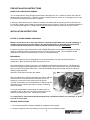
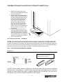
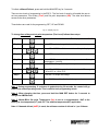
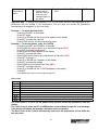
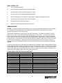
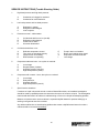
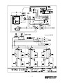
Installation & Operations Manual
Master-Bilt Products
908 Highway 15 North
New Albany, MS 38652
Phone: (800) 684-8988
PN 228-90000
Rev 05-04-04 bhs
2
TABLE OF CONTENTS
INTRODUCTION………………………………….……………………………………………………………………
4
STORE CONDITIONS…………………………….……………….…..…………………………………………….. 4
WARNING LABELS AND SAFETY INSTRUCTIONS………..…..……………………………………………… 5
PRE-INSTALLATION INSTRUCTIONS………………………..…..………………………………….…………… 6
Inspection for ShippingDamage……………………………………………………………….…………… 6
INSTALLATION INSTRUCTIONS………………………………………………………………………………….. 6
General Instructions…………………………………………………………………………………………. 6
Electrical...……………………………………………………………………………………………………..6
Leg and Condensate Pan Installation…..…………………………………………………………………..7
ELECTRONIC REFRIGERATION CONTROL (ERC)………….…………………………………….……………8
FINAL CHECK LIST…………………………………………………………………………………….…………….12
SENSOR PROBE ………………………………………………………………………………….……………….13
SERVICE INSTRUCTIONS…………………………………………………………………………………………..14
MASTER-BILT PART NUMBERS…………………………………………………………………………………..15
SALE AND DISPOSAL………………………………………………..…………………………………………… 16
WIRING DIAGRAMS……………………………………………………………… ……………………………..17-18
3
INTRODUCTION
Thank you for purchasing a Master-Bilt cabinet. This manual contains important instructions for installing,
using and servicing a Master-Bilt TAF ERC2 case. A parts list is included in with this manual. Read all these
documents carefully before installing or servicing your equipment.
STORE CONDITIONS
The Master-Bilt TAF ERC2 cases are designed to operate in the controlled environment of an air-conditioned
store. The store temperature should be at or below 75°F and a relative humidity of 55% or less. At higher
temperature or humidity conditions, the performance of these cases may be affected and the capacity
diminished. It is not uncommon in a newly constructed store for the temperature and humidity to be above
design conditions. These excessive conditions may produce sweating in the case until the store is operational
and the ambient environment is more desirable.
The Master-Bilt TAF ERC2 should not be positioned where it is directly exposed to rays of sun or near a direct
source of radiant heat or airflow. This will adversely affect the case and will result in poor performance.
If this case is to be located against a wall there should be at least 6” space between the wall and the back of
the case (see page 7). This space will allow for the circulation of air behind the case, which will prevent
condensation on the exterior surfaces.
NOTICE
Read this manual before installing your cabinet. Keep the manual and refer to it before doing any
service on the equipment. Failure to do so could result in personal injury or damage to the cabinet.
DANGER
Improper or faulty hook-up of electrical components of the refrigeration units can result in severe
injury or death.
All electrical wiring hook-ups must be done in accordance with all applicable local, regional or national
standards.
NOTICE
Installation and service of the refrigeration and electrical components of the cabinet must be
performed by a refrigeration mechanic and/or a licensed electrician.
The portions of this manual covering refrigeration and electrical components contain technical instructions
intended only for persons qualified to perform refrigeration and electrical work.
This manual cannot cover every installation, use or service situation. If you need additional information, call or
write us:
Customer Service Department
Master-Bilt Products
Highway 15 North
New Albany, MS 38652
Phone (800) 684-8988
Fax (800) 684-8988
4
WARNING LABELS AND SAFETY INSTRUCTIONS
This symbol is the safety-alert symbol. When you see this symbol on your cabinet or in this
manual, be alert to the potential for personal injury or damage to your equipment.
Be sure you understand all safety messages and always follow recommended precautions and safe operating
practices.
NOTICE TO EMPLOYERS
You must make sure that everyone who installs, uses or services your cabinet is thoroughly familiar
with all safety information and procedures.
Important safety information is presented in this section and throughout this section and throughout the
manual. The following signal words are used in the warnings and safety messages:
DANGER:
Severe injury or death will occur if you ignore the message.
WARNING: Severe injury or death can occur if you ignore the message.
CAUTION: Minor injury or damage to your cabinet can occur if you ignore the message.
NOTICE:
This is important installation, operation or service information. If you ignore the
message, you may damage your cabinet.
The warning and safety labels shown throughout this manual are placed on your Master-Bilt Products
cabinet at the factory. Follow all warning label instructions. If any warning or safety labels become
lost or damaged, call your customer service department at (800) 684-8988 for replacements.
CAUTION!
GROUND REQUIRED
FOR SAFE OPERATION
This label is located on top of the electrical control
label and on the wiring channel.
This label is attached to the cabinet power cord
on models with a power cord.
5
PRE-INSTALLATION INSTRUCTIONS
INSPECTION FOR SHIPPING DAMAGE
You are responsible for filing all freight claims with the delivering truck line. Inspect all cartons and crates for
damage as soon as they arrive. If damage is noted to shipping crates or cartons or if a shortage is found, note
this on the bill of lading (all copies) prior to signing.
If damage is discovered when the cabinet is uncrated, immediately call the delivering truck line and follow up
the call with a written report indicating concealed damage to your shipment. Ask for an immediate inspection of
your concealed damage item. Crating material must be retained to show the inspector from the truck line.
INSTALLATION INSTRUCTIONS
NOTICE TO STORE OWNERS / MANAGERS
Moisture or liquid around or under the cabinet is a potential slip/fall hazard for persons walking by or
working in the general area of the cabinet. Any cabinet malfunction or housekeeping problem that
creates a slip/fall hazard around or under the cabinet should be corrected immediately.
If moisture or liquid is observed around or under a Master-Bilt cabinet, an immediate investigation should be
made by qualified personnel to determine the source of the moisture or liquid. The investigation should
determine if the cabinet is malfunctioning or if there is a drainpipe leaking.
MECHANICAL
Remove front grille and check refrigeration lines to see that they are free (not touching each other or
compressor). Spin condenser fan blade to see that it is free.
Check that all service valves (2) are open. Cut compressor hold-down strap and remove. The springs are
secured for shipping by either tightening bolts or shipping strap. Remove the strap or loosen the hold-down
bolts so that the compressor floats freely. Check all refrigeration lines and electrical conduit for rubbing or
chaffing, paying particular
attention to area where lines enter the cabinet.
Remove cabinet from crate base and slide into location. Cabinet
must be level from side to side and front to back for correct
draining of coil pan and for self-closing doors to operate
correctly. Allow minimum of 4” between back of cabinet and wall
and between top of cabinet and ceiling for proper condensing
unit air circulation.
To comply with Sanitation requirements the cabinet must be
mounted on legs (6” high min.) or casters or the base must be
sealed to the floor with an N.S.F. listed silicone sealant.
To comply with UL requirements the cabinet must have a minimum clearance of 4” at the top, 6” at the
rear and 0” at each side.
GENERAL INSTRUCTIONS
1. Be sure the equipment is properly installed by competent service people.
2. Keep the equipment clean and sanitary so it will meet your local sanitation codes.
6
3. Rotate your stock so that older stock does not accumulate. This is especially important for ice
cream. A "First-In, First-Out" rotation practice will keep the products in good salable condition.
4. Do not place product in the case when it is soft or partially thawed. Also, product should not be put in the
case for at least 6 hours after it is started.
5. Stock cases as quickly as possible, exposing only small quantities to store temperatures for short periods of
time.
6. When replacing burned out fluorescent tubes, be sure that the electrical power to the lighting circuit is
turned off.
ELECTRICAL
WARNING
Before servicing electrical components in the case or the doors or door frames make sure all power to
case is off. Always use a qualified technician.
LEG AND CONDENSATE PAN
INSTALLATION FOR TOP MOUNT
CABINETS ONLY
To comply with Sanitation requirements this
cabinet must be mounted on casters, legs (6”
high min.) or the base must be sealed to the
floor. The casters provided with this case
screw into the holes from which the shipping
bolts were removed.
7
CONDENSATE PAN INSTALLATION FOR TOP MOUNT CABINETS ONLY
1. Before moving cabinet into place,
remove the condensate pan from the
top unit compartment.
2. Using the two screws supplied with
the pan, attach the pan to the back of
the cabinet at the two holes near the
bottom of the plastic drain line. Be
sure pan is NOT located directly
under cabinet. When the pan is
attached, feed drain line into the
open hole in screen and clamp the
heater conduit to the back of the
cabinet. Due to this condensate pan,
this case must be a minimum of 6”
from the wall.
3. If cabinet must be located next to
wall on legs, the pan can be located
under the cabinet. When this is done,
steam will accumulate on the bottom
of the cabinet if there is not adequate
ventilation, and rusting of the bottom
of the cabinet will occur.
4.
Low Temperature Freezers – TAF Models
The TAF - 27 models are cord connected and operate on a 15 amp, 115/60/1 circuit. The TAF – 48 and TAF74 models have two junction boxes mounted on top of the cabinet, at the right rear, for permanent connection
to power. One junction box is labeled 115v. (black, white and green lead) ; the other is labeled 230v. (black, red
and green lead). These boxes should be connected to their respective power source. Check inside the cabinet
for the power requirement for each cabinet. The label is located in the upper left hand corner.
ERC 2 – ELECTRONIC REFRIGERATION CONTROL
Programming
To access the pushbuttons on the ERC2,
flip up the front cover using the tabs on
the side of the cover as shown.
The ERC 2 control initially powers up displaying 12:00 AM otherwise it will show the last configured
selection (time or temperature). If a power outage occurs during normal operation, the control will
maintain the correct time-of-day using a capacitor (batteries are not required). The time will be
maintained for up to 100 hours when the capacitor is fully charged.
8
To initiate a Manual Defrost, press and hold the MAN DEF key for 3 seconds.
There are two levels of programming in the ERC 2. The first level of security will enable the user to
set two parameters: Time-of-day (CLoC) and Set point temperature (SEt). The other level allows
access to the other parameters.
Three buttons are used for the programming: SET, UP and DOWN
Fig. 4 – Display Lay-out
To change time-of-day and set point temperature (First Level) follows these steps:
Step 1
Press and hold set for 5 seconds. The display will show CLoC
Step 2
Press SET again to change the time-of-day
Step 3
Press UP or DOWN until the correct time-of-day is displayed
or
Step 4
Press SET to accept the new time
Step 5
Press DOWN to go to the next parameter – Set point
Temperature - (cut out)
Step 6
Press SET to change the set point temperature
Step 7
Press UP or DOWN to go to the desired set point. The range is
– 40 to 60°F or –40 to 16°C
or
Step 8
Press SET to accept the change
Step 9
Press DOWN to exit the first level of programming
Note 1: During programming, if no button is pushed during 30 seconds, the control will go
back to the normal operating mode. This is valid for both programming levels.
Note 2: When changing the time, press and hold the MAN DEF button for 3 seconds to
change the AM/PM mode.
Note 3: Master-Bilt’s Set point Temperature (Set) is set at a recommended –10°F at the
o
factory for low temperature(LT) and +35 F for medium temperature(MT) application.
Note 4: If demand defrost (ddEF) is used, the minimum number of defrost is 1 per 24 hours.
9
To change the other parameters (Second Level) follow these steps:
Press and hold SET and DOWN for 10 seconds. The display
will show dSPL
Step 1
and
Step 2
Press SET to change the parameter
Step 3
Press UP or DOWN to change the options, time or temperature
for the current parameter
or
Step 4
Press SET to accept the new value
Step 5
Press DOWN to go to the next parameter, then go back to Step
2. After the last parameter is displayed (ALHi), the display will
go back to the normal operating condition
Note: to scroll down the parameters without changing them, press the DOWN button.
List of Parameters
Here is a list of the parameters that can be changed in the Second Level of programming, as well as
their options and ranges.
Note: Master-Bilt’s Set point Temperature (Set) is set at a recommended –10°F at the
factory.
Parameter
Displa Description
Range / Options
Mastery
Bilt’s
Symbo
Factory
l
Setting
Display Status
dSPL Information shown
tdAy – time-of-day
on the display
rSP
rSP° – zone temperature
during operation
CyCL – cycle between time and
conditions
zone temperature
Epr° – evaporator coil temperature
Clock Format
CLHr
Time Format(12 or
12Hr – AM/PM format
12Hr
24 hours mode)
24Hr – 24 hour format
Temperature
Temperature
°dSP
°F – degrees Fahrenheit
°F
Format
degrees
°C – degrees Celsius
Defrost Type
dFtP
Type of defrost used ELEC – electric defrost / off cycle
ELEC
in the application
HgAS – hot gas defrost
Fan Status
EFAN Enable or not the
no – fan is turned off during defrost No – for LT
During Defrost
fan during defrost yES – fan remains on during defrost yES–for MT
Fan Status
on
CFAN Enable or not fan during on – fan on during normal mode
normal compressor
During Normal
CyCP – fan cycles with compressor
on/off mode
Mode
Defrost
Interval
dFin
Type of defrost
interval
Minimum
Compressor
Off Time
CoFF
Minimum time that
the compressor
remain turned off
TdAy – time-of-day setpoint
CPrn – compressor run time
tdEF – temperature initiated defrost
ddEF – demand initiated defrost
Range: from 0 to 15 min
10
ddEF–for LT
CPrn–for MT
2 min.
Minimum
Compressor
On Time
Alarm Delay
Con
ALrd
Compressor
Run Time
CPrn
Number of
Defrosts
Defrost Start
Time
Defrost
Duration
nodF
dEF1-8
dEFd
Minimum time that
the compressor
remain turned on
Time delay before
the alarm goes off
after the
temperature fall
off the two alarm
set points
Time the
compressor runs
between defrosts
Number of defrosts
per day
Start time of each
defrost
Defrost duration
time (back-up for
defrost
termination
temperature)
Delay time for the
fan after defrost
(back-up for fan
cut-in
temperature)
Pump down duration
Drip time duration
Range: from 0 to 15 min
2 min.
Range: from 0 to 59 min
30 – for LT
45 – for MT
12 – for MT
from 0 to 8 (0 means 1 defrost N/A – for LT
every 48 hours)
0 – for MT
N/A
Range: from 0 min to 4 hours
35 – for LT
0 – for MT
Range: from 0 to 15 min
2 – for LT
0 – for MT
Range: from 0 to 59 min
Range: from 0 to 59 min
0 min.
2 – for LT
0 – for MT
10° F–for LT
o
7 F – for MT
Fan Delay
FAnd
Pump Down
Drip Time
Pudn
driP
Setpoint
Differential
diF°
Cut-in temperature
differential
Note: cut-in is cutout plus differential
Range: from 1 to 25°
Temperature
Initiated
Defrost
Defrost
Termination
Temperature
tdEF
Temperature that
will initiate a
defrost cycle
Temperature in the
evaporator that
will terminate the
defrost cycle
Temperature in the
evaporator that
will turn the fan
on after defrost
Range: from – 40 to 40°F or – 40 to N/A
4°C
dEF°
Fan Cut-In
Temperature
FAn°
Low
Temperature
Alarm
ALLo
Range: from 0 to 75°F or –18 to 50° F
25°C
Range: from – 40 to 60°F or – 40 to 30° F–for LT
o
60 F–for MT
23°C
Low temperature
setpoint that will
make the alarm go
off and the error
message appear on
the display
11
Range: from – 40 to 83°F or – 40 to -40° F–for LT
32oF–for MT
23°C
High
Temperature
Alarm
ALHi
High temperature
setpoint that will
make the alarm go
off and the error
message appear on
the display
Range: from – 40 to 83°F or –40 to 50° F
23°C
Important Note: To change from degrees C to F or vice-versa, the user must reprogram all the
parameters that are related to the temperature. The unit does not convert the parameters
automatically from degrees F to C or vice-versa.
Example 1 - To adjust the time-of-day
- Press and hold SET for 5 seconds
- Press SET again
- Press UP or DOWN until the correct time appears on the display
- Press SET to accept the new time
- Press DOWN twice to exit the programming mode
Example 2 - To set one defrost a day, at 11:59 PM
- Press and hold SET and DOWN for 10 seconds
- Press DOWN five times to get to go to the Defrost Interval (dFIn)
- Press SET to change the parameter
- Press DOWN until tdAy appears on the display
- Press SET to accept the option
- Press DOWN seven times to go to the Number of Defrosts (noDF)
- Press SET to change it
- Press UP or DOWN until 1 appears on the display
- Press SET to accept the change
- Press DOWN to go to Defrost Start Time (dEF1)
- Press SET to change the time
- Press UP or DOWN until the 11:59 PM appears on the display
- Press SET
-
Press DOWN ten times to exit the programming level
Error Codes
Display
Er 1
Control Status
ERC Fault – software or hardware failure
ERC Communication Fault – indicates that there is a problem with the display module cable
Zone Sensor Fault – indicates an open or shorted temperature sensor
Evaporator Sensor Fault – indicates an open or shorted evaporator sensor
ERC Fault – software or hardware failure
Low Temperature Alarm – indicates that the temperature has dropped below the low alarm setpoint
High Temperature Alarm – indicates that the temperature has gone above the high alarm setpoint
Relay and display modules are incompatible
Er 2
Er 3
Er 4
Er 5
Er 6
Er 7
Er 8
For Error Codes 1, 2 and 5 cut the power to the unit and correct the problem to reset the
display.
For Codes 3 and 4, press the UP or DOWN button on the display to reset the error message.
If the display still shows the message, the sensor must be replaced.
The Error Codes 6 and 7 will be automatically reset once the temperature is back within the
two set points.
12
FINAL CHECK LIST
A.
Check operating pressures.
B.
Check electrical requirements of unit to supply voltage.
C.
Set temperature control for desired temperature range.
D.
Check system for proper defrost settings and operation.
E.
Check condensing unit for vibrating or rubbing tubing. Dampen and clamp as required.
F.
All valves should be completely open counter-clockwise.
G.
Check packing nuts on all service valves.
H.
Replace all service valve caps and latch unit covers.
SENSOR PROBE
NOTICE: If the probe assembly is disconnected from the main board during normal operation (unit running),
the connectors must be installed in the same position that they had before disconnection (P1 and P2),
otherwise the control will not function properly.
The Electronic Refrigeration Control sensors have NTC thermistors. The reference resistance is 30,000
ohms at 77°F (25°C). It carries NTC thermistors with a range of –40° to 199° F. In case there is a failure,
these sensors should be used in replacement of the sensors shipped with the control. In order to diagnose
faults in the probe, the control has LED functions as a diagnostic tool. When power is supplied to the control,
the LED will turn on and will remain on as long as this condition is satisfied. When there is a fault in the probe,
the LED will blink intermittently. When this occurs, the probe assembly needs to be replaced. If power is
supplied to the control and the LED remains off, there is a failure in the main relay control and it needs to be
replaced.
In case of a probe failure, the control will go into a safety mode of operation. While in safety mode the control
ignores probe inputs and cycles the compressor on for 5 minutes and off for 3 hours. The LED will be blinking
and signaling that there is something wrong with the probe. To replace the sensor probes, disconnect power
to the control, replace the probes and restart the unit. Since the wire is fixed to the cabinet, a technician may
cut the sensor wire inside the cabinet and splice it with a new sensor.
SENSOR PROBE TEMPERATURE AND RESISTANCE
Temperature
°F
°C
-29.2
-34
-20.2
-29
-9.4
-23
-0.4
-18
10.4
-12
19.4
-7
30.2
-1
32.0
0
39.2
4
50.0
10
60.8
16
69.8
21
80.6
27
89.6
32
13
Resistance
Ohms
683,100
499,200
347,100
259,500
185,200
141,200
103,100
97,950
80,040
59,700
45,000
35,820
27,500
22,210
SERVICE INSTRUCTIONS (Trouble Shooting Guide)
1.
High head pressure and high back pressure:
A.
B.
2.
Low back pressure and low head pressure:
A.
B.
C.
3.
E.
F.
G.
I.
P-trap in drain not installed.
Doors aren’t sealing when closed.
Evaporator fan motor defective.
Low voltage.
Low voltage.
Dropped phase (3 phase).
Overload protector defective.
High head pressure (see#1).
Compressor will not start – hums, but cycles on overload:
A.
B.
C.
D.
7.
Defective temperature control.
Time clock not operating properly.
Improper time clock setting.
Defrost heater not operating.
Compressor starts and runs – but cycles on overload:
A.
B.
C.
D.
6.
Coil blocked with frost or ice (see #4).
Refrigerant undercharged.
Control set too warm.
Air screen disturbance.
Coil blocked with frost or ice:
A.
B.
C.
D.
5.
Restriction in system.
Refrigerant undercharged.
Leak in system.
Pressures normal – cabinet warm:
A.
B.
C.
D.
4.
Condenser coil clogged or restricted.
Condenser fan motor defective.
Low voltage.
Relay defective.
Overload defective.
High head pressure (see #1).
Special service situations:
If moisture or liquid is observed around or under a Master-Bilt cabinet, an immediate investigation
should be made by qualified personnel to determine the source of moisture or liquid. The investigation
made should determine if the cabinet is malfunctioning or if there is a simple housekeeping problem.
Moisture or liquid around or under a cabinet is a potential slip/fall hazard for persons walking by or
working in the general area of the cabinet.
Any cabinet malfunction or housekeeping problem that creates a slip/fall hazard around or under a
cabinet should be corrected immediately.
14
MASTER-BILT PART NUMBERS
The table below gives Master-Bilt part numbers. Use this chart when ordering replacement parts for your TAF
ERC2 cases.
Description
TAF-27
TAF-48
TAF-74
Bulb
23-00343
23-00343
23-00343
Bulb Holder
23-01080
23-01080
23-01080
Bulb Shield
23-01465
23-01465
23-01465
Caster W \ Brake
27-00591
27-00591
27-00591
Casters W \ O Brake
27-00590
27-00590
27-00590
Coil Defrost Heater
17-00443
17-09113
17-09076
Condensate Heater
17-00421
17-00421
17-00421
Condensing Unit
01-01488
01-01510
01-01487
19-13761
19-13761
19-13761
Controller Kit*
10’ Cable
19-13760
19-13760
19-13760
Controller Display
19-13756
19-13756
19-13756
T-Sensor (2)
19-13758
19-13758
19-13758
Door Frame Heater
17-09449
17-09142
17-09142
Door Gasket
37-01207
37-01211
37-01211
Door Handle
35-01488
35-01488
35-01488
Door Hinge Assembly
A35-01501
A35-01501
A35-01501
Door Light Switch
35-01506
35-01506
35-01506
Door Opening Trim
29-01481
29-01481
29-01481
Drain Line Heater
17-00404
17-00404
17-00404
Drier
09-09171
09-09506
09-09506
Evaporator Coil
07-00750
07-13089
07-13089
Evaporator Fan Blade
15-01184
15-01184
15-01184
Evaporator Fan Guard
25-00205
25-00205
25-00205
Evaporator Fan Motor
13-00685
13-00685
13-00685
Expansion Valve
09-09187
09-09542
09-09542
Female Plug
21-00577
Heater Safety Control
19-01307
19-01164
19-01164
Leg
27-00558
27-00558
27-00558
Pilaster
33-01408
33-01408
33-01408
Pressure Control
19-13173
19-13173
Power Cord
21-01454
21-01454
Shelf Clips
33-01011
33-01011
33-01011
Shelves
33-01455
33-01456
33-01456
*The control kit has an optional Alarm Transformer for 115 volts (part #19-13190), 230 volts (part #19-13190),
and Buzzer (part# 19-13759)
15
SALE AND DISPOSAL
OWNER RESPONSIBILITY
If you sell or give away your Master-Bilt cabinet you must make sure that all safety labels and the Installation Service Manual are included with it. If you need replacement labels or manuals, Master-Bilt will provide them
free. Contact the customer service department at Master-Bilt at (800) 684-8988.
The customer service department at Master-Bilt should be contacted at the time of sale or disposal of your
cabinet so records may be kept of its new location.
If you sell or give away your Master-Bilt cabinet and you evacuate the refrigerant charge before shipment,
Master-Bilt recommends that the refrigerant charge be properly recovered in compliance with section 608 of
the Clean Air Act effective November 1995 and in accordance with all applicable local, regional, or national
standards.
16
17
18