1
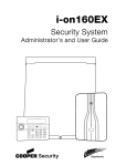
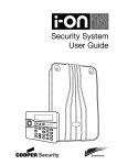
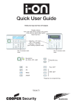
Security System
Administrator’s Guide
© Cooper Security Ltd. 2009
Every effort has been made to ensure that the contents of this book are correct.
However, neither the authors nor Cooper Security Limited accept any liability for
loss or damage caused or alleged to be caused directly or indirectly by this book.
The contents of this book are subject to change without notice.
Printed and published in the U.K
Part Number 11940859 Issue 1
Warning: Mains voltages are present inside control unit. No user
serviceable parts inside.
Page ii
Contents
1. Introduction .................................................... 1
Setting, Unsetting and Security Levels ...................3
Partitions and Security Levels............................3
24 Hour Alarms ...............................................4
Communications .................................................4
Controls and Displays ..........................................4
Controls: ........................................................5
Displays .........................................................6
Types of User .....................................................7
Access to the System ..........................................7
Proximity Tags ................................................8
Remote Controls..............................................9
2. Alarms ........................................................... 10
Silencing an Alarm ............................................ 10
Remote Reset (aka Anti-Code Reset) ................... 11
Speech Messages.............................................. 12
Acknowledging a Speech Message.................... 12
3. Alerts (or Why is it Beeping?) ....................... 13
4. Administration............................................... 14
Entering and Leaving the Menu ........................... 14
Editing Text ..................................................... 14
Omitting Zones................................................. 15
Users .............................................................. 16
Editing Existing Users..................................... 16
Adding Users ................................................ 21
Deleting Users .............................................. 22
Viewing the Log ................................................ 22
Testing the System ........................................... 23
System Configuration ........................................ 24
Switching the Chime On/Off ............................ 25
Setting the Date and Time .............................. 25
Programming Outputs .................................... 26
Programming Remote Controls for Users........... 27
Deleting Remote Controls ............................... 29
Starting a Call To Downloader ......................... 29
Redirecting Speech Messages .......................... 30
Turning Outputs On/Off ..................................... 31
What System Have I Got? .................................. 31
Page iii
List of Menu Options ......................................... 32
Page iv
i-on40
1. Introduction
The i-on40 is an intruder alarm system intended mainly for use in
larger domestic and medium sized commercial properties.
The heart of the i-on40 system is the control unit and its keypads.
The control unit contains the main wireless receiver, the power
supply and stand-by battery. The stand-by battery can keep the
alarm system going for up to 12 hours if the mains supply fails.
Connected to the control unit by cable are up to four keypads.
Each keypad has a two line display to show you status
information, and various keys for operating the system. The
keypad also contains a speaker to give warning tones when the
system is setting or unsetting.
Users identify themselves to the system by keying in access
codes. If they do not wish to use access codes then the keypads
also contain proximity tag readers, allowing users to identify
themselves by means of small electronic tags that they carry with
them.
To protect an area the control unit can operate a range of
detectors. Detectors can either be connected to the control unit
by wires, or communicate back to the control unit’s receiver using
a small radio transmitter. Figure 1 shows some examples. In
addition to fixed detectors the control unit can also monitor small
portable transmitters that users can employ to start alarms
remotely, for example in the case of a panic alarm.
When the control unit detects an alarm, it can start an external
sounder/strobe unit by sending the appropriate radio signal. In
addition the control unit can also communicate using a variety of
plug on modules. Some modules also provides speech recording
and playback facilities so that the system can send recorded
speech messages to pre-programmed telephone numbers.
The control unit also provides sets of connectors for outputs,
which the installer can use to link the control unit to siren/strobe
units or other equipment.
Page 1
Introduction
i-on40
A
B
1. Two button panic alarm.
2. Two button panic alarm with tilt
switch.
3. Two button panic alarm.
A
1
2 abc
3 def
B
4 ghi
5 jkl
6 mno
C
7 pqrs
8 tuv
9 wxyz
D
*
0
#
4. Four button remote control.
5. Wireless arming station.
6. Door Contact/Universal Transmitter.
7. Smoke Detector.
8. Passive Infra Red.
9. External siren/strobe.
Figure 1. i-on40 Peripherals
A complete i-on40 system comprises a control unit and up to:
24 fixed wireless alarm detectors
Up to 16 fixed wired alarm detectors
Five external siren/strobe unit (one wired, four radio)
50 portable four button remote controls
50 portable two button panic alarms
50 users.
Page 2
i-on40
Introduction
Setting, Unsetting and Security
Levels
The majority of alarm systems are intended to detect the
movements of people, and to notify others when people move
into protected areas. Readying the system to start an alarm when
someone moves into a protected area is called “setting” the
system. Disarming the system so that people can move freely is
called “unsetting” the system.
The installer can program the alarm system to give you a choice
of which areas to protect by assigning detectors to different
“security levels”. Each security level is a collection of one or more
detectors that monitors a different area. The highest security level
is called Full Set, and includes all the detectors. There are three
other security levels called Part Set B, C and D. For example, in a
family home Full Set might monitor the whole house and outbuildings, while Part Set B might monitor just the downstairs
rooms and external doors.
Partitions and Security Levels
At a site where all users have complete access to the whole alarm
system, then the installer can program the i-on40 to provide four
levels of security: Full Set and three different Part Sets. Any user
can put the alarm system into any of the security levels.
If the system is installed at a site where some users must have
restricted access to parts of the alarm system, then the installer
can split the i-on40 electronically into four separate “partitions”.
Users can set and unset each partition completely independently
of all the others. Individual users can be given access to one or
more partitions: if they have no access to a partition then they
can not set or unset that partition. In effect the i-on40 becomes
four separate alarm systems.
In addition each partition can be programmed to set at one of two
security levels: either Full Set or Part Set B. Any user who is
allowed to set a partition can select either of the two security
levels.
Page 3
Introduction
i-on40
24 Hour Alarms
The control unit can also monitor detectors that are nothing to do
with the movements of people: fire and smoke detectors, flood
sensors, panic alarm buttons, or monitors for machinery (for
example freezers). These are collectively known as “24-hour
alarms” because they can cause an alarm 24 hours a day: it does
not matter whether a user has set or unset the system.
Communications
As well as triggering a sounder during an alarm, the i-on40 can
also be fitted with communication modules that allow the control
unit to send alarm information over the telephone network, the
mobile phone network, or the internet. There are separate
modules for each of these different tasks. Ask your installer what
type of module you have fitted.
As part of the communication capability the installer may also be
able to call into your control unit and program it remotely.
Depending on how your installer has programmed the system you
may receive a phone call from them asking you to give them
access to your alarm system.
Controls and Displays
Figure 2 shows the controls and displays available on the keypad.
1. LCD display .
1
2. Programming keys.
2
7
3
4
5
A
1
2 abc
3 def
B
4 ghi
5 jkl
6 mno
C
7 pqrs
8 tuv
9 wxyz
D
*
0
#
6
3. Navigation key
4. Setting and unsetting
keys.
5. Panic Alarm (PA)
keys.
6. Alpha/numeric keys.
7. Set/Unset status
LEDs.
Figure 2. Controls and Displays
Page 4
i-on40
Introduction
Controls:
A
Full Sets the system. (All detectors in use.) In a
partitioned system this key’s function can be programmed
by the installer.
B, C Part Sets the system. (Some of the detectors in use.) In a
and D partitioned system their function can be programmed by
the installer.
Unsets the system.
u
In menus: scroll up. In text editing: move cursor left
n
In menus: scroll down. In text editing: move cursor right.
>
If the bottom line of the display shows a “>” at the right
then pressing this key selects the submenu named on that
line.
If the bottom line of the display shows “On” “Off” “Yes”
“No” “I” (for include) “O” (for omit) then pressing this key
changes the value to its opposite.
<
Deletes characters when editing names.
Y
Press this key to confirm a decision and save any
changes.
X
a) Moves the display to a higher level of the menu.
b) Press this key to abandon your decision when the
display shows “Are you sure Y/N?”
Press this key to gain access to the Menu.
1 to 0, Used to key in access codes. Can also be used to key in
*, # text for names, and telephone numbers.
#
Used when keying in text: press to change between
capitals or small letters.
Press these keys to start a Panic Alarm. (Press both at the
same time.)
Page 5
Introduction
i-on40
Displays
The LCD display shows messages and prompts to help guide you
through setting, unsetting, resetting and programming the
system.
When the system is idle (either while
set or unset) the display shows the
“standby screen”, comprising the time
and date:
I-ON40
11:15 20/6/09
(The top line of the display may show the installer’s name
instead of “i-on40”.)
To draw your attention to special events the rim of the navigation
key glows red.
The four LEDs on the right of the programming keys show you
whether the system is set or unset:
In a part setting system, the left hand LED glows when the
system is full set, the other LEDs glow when the system is in
one of the part set states.
In a partitioned system, each LED represents on partition. The
left hand LED is partition 1, and the right hand LED is partition
4. If a LED is glowing continuously the partition is full set. The
LED flashes slowly when the partition is part set.
Note that the installer can disable these LEDs in order to hide the
state of the system (this may be required in order to comply with
local standards).
Detectors or Zones?
When talking about alarm systems, people tend to use the words
“detectors” and “zones” interchangeably. Most of the time this
doesn’t matter, but occasionally it can cause some confusion. In
this book a “detector” is a physical piece of equipment that
signals some event. A “zone” is how the keypad reports the
location of the detector.
The reason for this is that an installer may connect several
detectors together to guard one “zone” (an area of a building for
example). The control unit cannot tell that this has happened, so
it is easier for the keypad to report an alarm from a “zone”. Most
Page 6
i-on40
Introduction
of the time there is only one detector per zone, especially with
radio detectors.
Types of User
The i-on40 provides for five different types of user:
Master User This user can add other users to the system, edit
them, or remove them. There is always (at least) one master
user: User 01. Master users can create all other user types,
including other master users. No user can remove User 01 or
change their type. User 01 and all master users always belong to
all partitions.
Administrator This user is similar to a master user, but is limited
to one or more partitions. Admin users can create, delete or edit
other users (including Admin users) belonging to the same
partition(s) but cannot create or delete Master users. Admin users
can assign other users to any of the partitions that the Admin
user belongs to, but cannot assign users to partitions that the
Admin user does not belong to.
Normal User A normal user is assigned to one or more
partitions. They cannot add or delete other users. A normal user
can change their own access code, switch the Chime function on
and off, and operate any outputs that the installer has made
available. Normal users can set and unset their partitions at any
time.
Guard A guard can only unset a partition in alarm, reset it, and
then set the partition again.
Set Only This type of user can set the partition they are allocated
to, but cannot unset any partition.
For details on how to add and remove users see page 16 .
Access to the System
To operate the system a user must identify themselves, either by
entering an access code on the keypad or by presenting a
proximity tag (see next page) to the front of the keypad.
Page 7
Introduction
i-on40
Access code and tag act as unique identifiers for each user, and
may be used interchangeably at any time.
When delivered from the factory the control unit recognises just
one user, and this user has Master User privileges (see page ).
This user’s default access code is “1234”, and they do not have
any tag or other device registered to their account.
Cooper Security Limited recommend that you change the
default access code as soon as possible (see page 16).
The installer has a separate access code which they cannot use to
set or unset the alarm system. Neither can they use that code to
change details of other users registered to the system. Similarly,
the Administrator code has no access to any installer
programming menus.
Code Lockout
If a user has problems remembering their code, they may try
keying it in several times. If a user keys in an incorrect code 10
times in a row then the control unit locks all keypads for 90
seconds. Once the 90 seconds is finished then the keypads will
allow users to try again. Note that the system will log the fact that
someone has locked the keypads in this way by recording “Excess
keys”.
Proximity Tags
A proximity tag is a small plastic token with a low powered radio
transmitter inside. Each tag contains a unique identity code.
Inside the keypad is a sensor. When you present the tag within
about 10mm of the front of the keypad, the control unit senses
the presence of the tag and reads its identity code.
If a user presents a tag that the control unit recognises then the
control unit allows the user to access the system in the same way
as if they had keyed in a recognised access code.
Page 8
i-on40
Introduction
Remote Controls
A remote control is a transmitter that you can attach to a key
ring. The remote control has four buttons and a small LED that
glows when it transmits a signal. Note that the user must hold a
button down for at least two seconds to ensure a transmission.
When delivered from the factory three of the buttons are
dedicated to setting or unsetting the system (see Figure 3).
1.
2.
3.
4.
5.
Full Set.
Part Set.
Not used.
Unset.
Transmit LED.
A
B
Figure 3. Remote control Buttons.
Each remote control has a unique electronic identity. When you
assign a remote control to a user you teach the identity to the
control unit. You may assign one (and only one) remote control to
each user.
Page 9
i-on40
2. Alarms
The i-on40 normally starts an alarm when it receives an alarm
signal from one of its detectors. In addition, you can start a panic
alarm from the keypad. The table below shows the different kinds
of alarms possible.
Type of
Alarm
Intruder
Signal
(see note)
Started by:
Loud warbling
tone from
siren.
Normal alarm or entry route zone
activated when system is set.
Fire
Pulsing tone
from siren.
Fire zone activated at any time.
Panic
Loud warbling
tone from
siren
PA zone or Panic Alarm transmitter
activated at any time.
24 hour zone activated at any time.
Pressed on keypad.
(The installer must enable this
feature on your system.)
Technical
Loud warbling
tone from
siren.
Technical alarm zone activated at
any time.
Silencing an Alarm
In an alarm the i-on40 operates the sirens. The sirens run for a
limited time set by the installer (a maximum 15 minutes for
intruder and panic alarms).
If you return to the system while the sirens are running you can
silence the siren as follows:
1.
Key in your access code (or
present your tag to the
keypad)
Page 10
i-on40
The siren stops and the screen
shows the first zone to cause
the alarm, for example:
Alarms
Press tick to reset
Burg Z03 Alarm
(Press u or n to see the name
of the zone.)
2.
Press Y.
The display returns to normal.
If you return to the control unit after the sirens have stopped and
key in your access code then the red LEDs around the navigation
keys glow to tell you that an alarm has occurred. Press > to see
information about the alarm. (Press u or n to see the name of
the zone.) Press Y to restore the display to normal.
If you wish to see any other zones that were triggered during the
alarm, look in the log (see page 22).
Remote Reset (aka Anti-Code Reset)
The installer may have programmed your system so that you
cannot reset after an alarm.
The screen will tell you where the
alarm occurred, for example:
Press tick
Burg Z03 Alarm
It will also show a message asking
you to call the alarm company, for
example:
CALL ARC
Quote 1234
The number displayed on the bottom line is a special code
(“1234” is just an example). Note this code down, you will need it
when you talk to the alarm company.
Press Y to clear the message and the display returns to normal.
Call your alarm company and tell them that an alarm has
occurred.
When you talk to the alarm company, they will ask about the
circumstances of the alarm, and also for the code you recorded
from the display. If the alarm company decides that an engineer
does not need to visit you, then they will give you another four
digit code (the “anti-code”).
Page 11
Alarms
i-on40
Key in the anti-code at the keypad. The system will reset, and
you can carry on using it as before.
Speech Messages
Note: This facility requires fitting a communications module to
your alarm system, ask your installer for more details.
As well as making an audible signal, the installer can program the
i-on40 to send pre-recorded voice messages over the telephone
network. These messages can go to a person nominated to
monitor alarm calls.
Each message has two parts: a Home section that identifies your
system, and an alarm section that gives the nature of the alarm.
The control unit may be programmed to send the speech
message to several telephone numbers.
Acknowledging a Speech Message
If the control unit has Call Acknowledge enabled (ask your
installer), then the person receiving speech messages from the
alarm system can control the link by pressing buttons on their
telephone key pad. The commands available are:
Function
Key
End this call (and let the control unit contact
‘5’
the other destinations for this alarm)
Play ‘Home’ and ‘alarm’ message again
‘3’
Clear down (and do not call any of the other
‘9’
destinations for this alarm).
Note: When the called party answers a speech dialler call there is
a six second delay before the control unit starts playing the
home message.
Page 12
i-on40
3. Alerts (or Why is it Beeping?)
From time to time the control unit may detect that there is a
problem with the system. It will try to inform you of this by
starting an alert. During an alert the rim of the navigation pad
glows red, and the keypad will give an short “beep” every few
seconds.
To see the cause of the alert:
1.
Make sure the system is unset and that the keypad display
shows the standby screen.
2.
Press Y .
The display asks you to key in an access code.
3.
Key in a user access code.
The bottom line of the display shows a message describing
the most recent active alert.
4.
Either:
Press Y to acknowledge that you have read the alert.
If you press u or n then the system will show you any other
alerts that may be active. If there are no other alerts the rim
of the navigation pad will glow green and the keypad will
return to its’ standby screen. In addition the keypad will stop
beeping.
OR: Press X. The rim of the navigation pad will stay red and
the system will show the text of the alert the next time you
key in an access code. (The keypad will stop beeping.)
Note: 1. The system will not alert you to short interruptions of
mains power. If the cause of an alert goes away, then the
system will remove the Alert message.
2. The system records all alerts in the log, with the time
when you acknowledged them.
Page 13
i-on40
4. Administration
To make changes to the way your system works you must enter
the Menu. Your degree of access to the Menu depends on what
type of user you are: Master User, Admin User or Normal User.
A Master User has access to all the options of the Menu. A Master
User can add, change, or remove users in any partition, and has
full access to the system options menu.
An Admin user may be limited in the partitions that they can
access.
A Normal user has very limited access to the Menu: they can
change their own access code, switch Chime on or off, and
operate any outputs.
A Guard or a Set Only user have no access to the Menu at all.
Entering and Leaving the Menu
1.
Make sure the display shows the standby screen.
2.
Press
3.
Key in an access code.
.
The display shows the first item in a list of options. (See
page 32 for a complete list of options.)
4.
Press u or n to scroll through the options available, followed
by > to select (gain access) to an option.
5.
Press Y to confirm an option when you have finished making
changes.
6.
Press X (if necessary several times) to leave the Menu.
The rest of this chapter describes each of the main options in the
Menu.
Editing Text
For many of the items that you can program, the control unit lets
you assign a 12 character name. To key in text for the name
Page 14
i-on40
Administration
press each number key one or more times to obtain the letter you
want (the letters of the alphabet appear on the keys in the same
arrangement as on many mobile phones, see Figure 4.)
Press # to change between capitals and small letters.
The cursor becomes an underline when you type in small letters
and a block when you type in capitals.
Press u to move the cursor left, or n to move the cursor to the
right.
Press < to remove letters to the left of the cursor. Press > to
insert a space.
1
4 ghi
2 abc
3 def
ABC
DEF
5 jkl
6 mno
GHI
JKL
7 pqrs
8 tuv
PQRS
TUV
*
0
MNO
9 wxyz
WXYZ
#
Space 0
Figure 4. Letters Assigned to Keys
Omitting Zones
You may wish to prevent a zone causing an alarm. For example, if
your garage door is protected by a detector, but you wish to
leave it unlocked for the delivery of a parcel, you may wish to
omit that detector when you set the rest of the alarm system. To
do this the control unit allows you to "Omit" a zone.
1.
Enter the Menu and select Omit Zones.
The bottom line of the display shows the first of a list of
zones.
Page 15
Administration
2.
Press u or n to display the zone you wish to omit.
3.
Press > to mark the zone for omission.
i-on40
The character at the end of the line changes to an "O" to
show that the zone will be Omitted.
If you change your mind then press > again so that the end
of the line shows an "I" (for Included).
4.
Repeat steps 2 and 3 for any other zone you wish to omit (or
include).
5.
Press Y to store the changes you have made.
The control unit allows you to omit a zone for one
setting/unsetting cycle. You will have to omit the zone again for
the next setting/unsetting cycle.
Users
The control unit can recognise up to 50 individual users. Select
Users in the Menu to add new users, change their details, or to
delete them from the system.
Editing Existing Users
If you wish to change the details for an existing user then:
1.
Enter the Menu and select Users - Edit User.
The bottom line of the display shows the first in a list of the
users already programmed into the control unit.
2.
Press u or n to display the user you wish to edit, and then
press >.
The bottom line shows one of a list of the options that you
can edit:
Name: Use this option to give the user a 12 character name.
The display will show the name in menus, and in the log
when the user sets, unsets or resets the system.
Type: (Not available for User 01) Master, Admin, Normal,
Guard or Set Only.
Partitions: (Not in a part setting system) Use this option to
assign users to one or more partitions.
Page 16
i-on40
Administration
Code: The user’s access code.
Prox Tag: Use this option to assign a proximity tag to a user.
Remotes: Use this option to assign a remote to a user.
Panic Alarm: Use this option to assign a panic alarm
transmitter to a user.
Use the u or n keys to scroll through the list.
(The options available are the same as those shown when
adding a user.)
3.
Press > to select the option you wish to edit.
4.
Press Y when you have finished.
Name
If you wish to edit the name displayed on the keypad for a user:
1.
Enter the Menu and select Users - Edit User - User(nn) - Name.
The display shows the current name given to the user, and
places a cursor at the end of the name.
2.
Key in the name from the keypad. See Editing Text on page
14.
3.
Press Y when finished.
User Types
To change a user’s type:
1.
Enter the Menu and select Users - Edit User - User(nn) - Type.
2.
Press u or n to scroll through the list of user types.
3.
Press Y to select the user type you wish to assign to the user.
See page 7 for a description of the user types available.
Note: You cannot change User 01’s type.
Partitions
To assign a user to one or more partitions:
1.
Enter the Menu and select Users – Edit – User(nn) – Partitions.
2.
Press u or n to scroll through the list of partitions.
Page 17
Administration
i-on40
On the bottom line of the display “Yes” means that the user
is assigned to the partition, “No” means that the user is not
assigned to the partition.
3.
Press > to change the “Yes” to a “No” or back again.
See page 3 for a description of partitions.
Note: You cannot change User 01’s partitions. User 01 always
belongs to all partitions.
Access Code
To change a user’s access code:
1.
Enter the Menu and select Users - Edit User - User(nn) - Code.
2.
Key in an access code for the user.
When you press the last digit of the access code the display
asks you to key in the same access code again.
3.
Key in the same digits again, in the same order.
Access codes are four digits long.
Proximity Tags
To allocate a proximity tag to a user:
1.
Enter the Menu and select Users - Edit User - User(nn) - Prox Tag.
Note: If the user already has a prox tag allocated to them then
the screen will display “Delete Prox Tag?”. See page 20.
The display asks you to present a tag to the front of the
keypad.
2.
Hold the tag up close to the front of the keypad.
The control unit learns the identity of the tag.
You cannot register more than one tag per user. If you
present a tag that the control unit has already registered to
another user then you will hear a single low tone, the display
will tell that the tag is already in use and will then revert to
asking you to present the tag.
If you do not wish to register a tag for the user then press X.
Page 18
i-on40
Administration
If you have a proximity tag and want to know who it belongs to
then use the Test - Proximity Tag menu option, see page 23 .
Remote controls
To allocate a remote control to a user:
1.
Enter the Menu and select Users - Edit User - User(nn) - Remotes.
Note: If the user already has a remote control allocated to them
then the screen will display “Delete Remote?”. See page
20.
The display asks you to press one of the buttons on the
remote control.
2.
Press any button on the remote control that you wish to
register. Hold the button down until you see the transmit LED
flash.
When the remote control transmits, the control unit learns
the identity of the remote control and registers it to the user.
If you do not wish to register a remote control press X.
If the control unit has already learned that remote control then
you will hear a low tone and the display tells you that the remote
control is already in use.
If you have a remote control and want to know who it belongs to
then use the Test - Remotes menu option, see page 23 .
Panic Alarms (PA)
A PA is a two button transmitter, used to start a Panic Alarm. To
activate the transmitter you must press both buttons at the same
time. On some models a third button acts as a lock so that you
can prevent the PA going off when carrying it in your pocket.
Note: While you are registering a new PA the control unit will not
respond to an alarm signal from any PA it has already
learned.
To allocate a panic alarm to a user:
1.
Enter the Menu and select Users - Edit User - User(nn) - Panic
Alarm.
Page 19
Administration
i-on40
Note: If the user already has a PA allocated to them then the
screen will display “Delete PA?”. See “Deleting Remote
Controls, Tags and PAs” on page 20.
The display asks you to press both buttons on the PA.
2.
Squeeze both buttons on the PA.
When you squeeze the buttons the control unit learns the
identity of the PA and registers it to the user.
If you do not wish to register a PA press X.
You cannot register more than one PA per user. If the control unit
has already learned that PA then you will hear a low tone and the
display remains unchanged, asking you to press the buttons on
the PA.
If you have a PA and want to know who it belongs to then use the
Test - Panic Alarms menu option, see page 23 .
Deleting Remote Controls, Tags and PAs
If a user has lost a remote control, prox tag or panic alarm then
you should delete it from the system to make sure that no
unauthorised person can use it. Also, if you wish to reassign a
device to another user, you must first delete it from the system.
1.
Enter the Menu and select Users - Edit User.
The bottom line of the display shows the first in a list of the
users currently recognised by the system.
2.
Press u or n to display the user whose device you wish to
delete., then press >.
The bottom line of the display shows “Name”.
3.
Press u or n until the bottom line shows the device you wish
to delete, then press >.
If the user you selected in step 2 has a device registered to
them then the display asks if you wish to delete it, for
example: “Delete Panic Alarm?”.
4.
Press Y.
The display shows, for example, “Panic Alarm Deleted”.
Page 20
i-on40
Administration
To register a device with the user, re-enter the Menu and select
Users - Edit User. Select the user and then the device type you wish
to add.
If a remote control or PA has been stolen and the user it belonged
to no longer has an access code on the system, see page 29.
Adding Users
When adding a new user you can also assign to them proximity
tags, remote controls and panic alarm transmitters. If you do not
wish to assign these devices at the time then you can assign
them later by using the Users - Edit User option.
To add a new user:
1.
Enter the Menu and select Users - Add User.
The display shows a default user name, for example: “User
04”. Edit the name (for hints on editing text see page 14).
2.
Press Y when you have finished editing the name.
The display shows the default type for a new user (Normal
User, see page 7 for a description of user types).
3.
Select the type you want to assign to the new user and
press Y.
The display asks you to assign a new user code.
4.
Key in the user code you want the new user to employ. ( If
you do not want to assign a code to the user press Y.) Key
the code in a second time when prompted by the display.
The display asks you to present a proximity tag to the
keypad.
5.
Present an unused tag to the keypad. If you do not want to
assign one to the user press Y.
The display then asks you to press a button on any remote
control that you want to assign to the user.
6.
Press a button on a remote control (one that is not currently
registered to any other user). If you do not have one press
Y.
Page 21
Administration
i-on40
The display finally asks you to press both buttons on any PA
that you want to assign to the new user.
7.
Press both buttons on a PA that you wish to assign to the
user. If you do not have one for the user press Y.
The display should now tell you that the new user has been
added to the system.
Deleting Users
To remove a user from the system:
1.
Enter the Menu and select Users - Delete User.
The bottom line of the display shows the first user in a list of
the users recognised by the system.
2.
Press u or n until the display shows the user you want to
delete.
3.
Press >.
The display shows the message “Delete All Details”.
(If you change your mind at this point press X.)
4.
Press Y .
The control unit deletes the user from the system.
Once you delete a user, the system does not respond to their
access code or to their proximity tag. In addition, the control unit
"forgets" the identity of all remote controls and PAs assigned to
the user.
Viewing the Log
The control unit keeps a log of the last 1000 events (for example,
alarms and setting/unsetting events). To read the log:
1.
Enter the Menu and select View Log.
The display shows you the most recent log event.
2.
Press u or n to scroll through the log.
n shows earlier events, u shows more recent events.
Page 22
i-on40
3.
Administration
Press > to see a more detailed description of the event.
The display will show, for example, the name you keyed in
for a user.
4.
Press X to finish viewing the log.
Testing the System
If you think that your system is not working correctly then you
can use the Test option to test various peripherals. If the test
confirms that part of the system is not working then contact your
installer.
The Test option also lets you check the identity of Remote
controls, Panic Alarms and Tags.
To start testing, make sure the system is unset and the display
shows the time and date then:
1.
Enter the Menu and select Test.
The display shows the Test menu.
2.
Press u or n followed by > to select the part of the system
that you wish to test.
3.
Press X to stop the test.
You can test each part listed in the Test menu as follows:
Siren
Press > to turn the siren on and off again. The
word "On" or "Off" on the display shows whether
you should be hearing the siren.
Keypad
Press each key once. The display shows the key
you pressed. Press both PA keys together to test.
Press X to end the test.
Walk test
The display shows a list of all the detectors
installed on the system. The top line of the
display shows you how many detectors remain to
be tested. Walk round and trigger each detector.
Every time you trigger a detector the keypad
gives a double tone and the display shows an "A"
at the end of the line for that detector. Note that
Page 23
Administration
i-on40
you cannot test 24 hour or fire zones.
Outputs
The bottom line of the display shows the first in a
list of the outputs installed on the system. Select
the output you wish to test. Press Y to finish the
test.
NOTE: Make sure no one tries to activate an by
means of a remote control while you perform the
test.
When you complete the test check that the
output is still in the state you wish it to be in.
Remotes
Press any button on the remote control. The
display shows the identity and user of the remote
control, and the button that the control unit
believes you pressed. Press all the buttons on
the remote control in turn.
Panic Alarms
Press both buttons on the panic alarm
transmitter. The display shows the identity of the
user assigned to the panic alarm.
Proximity Tags Present the tag to the front of the keypad. The
display shows the user assigned to the tag.
System Configuration
The System Configuration option allows you to change some
parts of the system to suit your particular needs. If you need
more extensive changes to the operation of the system then you
must contact your installer.
Make sure the system is unset and the display shows the time
and date, then:
1.
Enter the Menu and select System Config.
Page 24
i-on40
Administration
The bottom line of the display shows the first item of the
System Configuration menu.
2.
Press u or n to scroll through the options available, followed
by > to gain access to an option.
Switching the Chime On/Off
The installer may have set up your alarm system to give a chime
tone whenever something triggers one or more detectors while
the system is unset. If you wish to switch this feature off (or on)
then:
1.
Enter the Menu and select System Config – Facilities On/Off.
The bottom line of the display shows the current state of the
chime feature, for example “Chime On” if chime is currently
working.
2.
Press > till the bottom line of the display shows the status
you want (for example “Chime Off” if you want to silence the
chime feature).
3.
Press Y to leave the option when you have finished making
changes.
Setting the Date and Time
You will need to re-program the date and time if the control unit
loses power for an extended time, and the battery is exhausted.
1.
Enter the Menu and select System Config – Set Date & Time.
The top line of the display shows “Set the date” and the
bottom line shows the current date in number format
(day/month/year). The day is highlighted.
2.
Key in the digits for the day/month/year (use leading
zeroes). Press Y when you have finished.
The top line of the display shows “Set the time” and the
bottom line of the display shows the current time in 24 hour
numerical format (hours: minutes). The hours are
highlighted.
3.
Key in the hours and minutes (user leading zeroes). Press Y
to finish.
Page 25
Administration
i-on40
Note: The internal clock adjusts itself for daylight saving in Spring
and Autumn.
Programming Outputs
During programming the installer may allocate some outputs so
that they can be reprogrammed by an Administrator. This section
describes how the Administrator can use those outputs.
For each output you can, if you wish, set and “on” time and an
“off” time so that the output will go on and off at fixed times each
day. In addition, Master, Admin and Normal users can switch the
output on or off at any time.
To program an output:
1.
In the User Menu select System Config - Edit Outputs.
The display shows the Edit Output menu, the bottom line
shows the first in a list of the available outputs.
Note: This option is only visible if the installer has allocated some
outputs to you.
2.
Press u or n to select the output you wish to edit then press
>.
The bottom line of the display shows “Name”, the first item
in a menu that allows you to change the name of the
selected output, and to set an “On” and “Off” time for the
output.
3.
Press u or n followed by > to select Name to give the
output a meaningful name. (Hint: see Editing Text on page
14.)
The name you give the output appears in all the other menus
the display offers for controlling outputs.
4.
Press u or n followed by > to select “On Time” to set a time
when the control unit will switch the output on.
5.
Press u or n followed by > to select “Off Time” to set a time
when the control unit will switch the output off. If you do not
wish the output to switch on and off at set time then leave
these two options set to “00:00”.
Page 26
i-on40
Administration
Note: You can switch the output on and off from the Menu by
selecting Outputs On/Off (see page 31).
If you want to program a telecommand to control the
output, see page 27.
Programming Remote Controls for Users
The System Config - Remotes option allows you to re-program buttons
on an i-fb01 remote control.
1.
Enter the Menu and select System Config - Remotes - Edit.
2.
EITHER Press the button you want to reprogram on the
remote control.
The display shows the identity and owner of the remote
control, and the button you pressed. Go to step 4.
OR If you do not have the remote control press >.
The display presents a list of the registered remote controls
and their users.
3.
Press u or n to show the remote control you want to edit.
Press > to select it.
The display shows the first button on the remote control.
4.
Press u or n to show the button you wish to re-program,
followed by > to select it.
Now that you have selected the button you wish to reprogram the display shows you the first of three options:
a) Set/unset some part of the system (see Set/Unset below).
b) Operate one of the outputs (see Operate an Output on
page 28) If you cannot see this option on the display then
the installer has not made any outputs available for users.
c) Do nothing (disable the button).
5.
Press u or n followed by > to select the option you wish to
use.
Set/Unset
If you selected Set/Unset in step 5 above:
The bottom line of the display shows either “Set” or “Unset”.
A “*” at the beginning of the line shows the option currently
Page 27
Administration
i-on40
in force.
“Set” means that the button is used for setting some
combination of partitions and/or Full Sets/Part Sets.
“Unset” means that the button is used for unsetting
partitions or the whole system.
6.
Press u or n followed by > to select the option you want.
Set
7.
Press >.
The bottom line of the display shows the first of the options
available:
Full Set All: The button will Full Set all partitions that the
user is allocated to.
Part Set All: The button will Part Set all the partitions the
user is allocated to.
Partitions: The display will show you a menu where you can
select Full Set, Part Set or No action for individual partitions.
(Hint: Press u or n to see each partition, press > to change
the action for each partition.)
Unset
7.
Press >.
The bottom line of the display shows the first of two options:
Unset All: The button will unset all the partitions that the
user is allocated to.
Partitions: The display will show you a menu where you can
select Unset or No action for individual partitions. (Hint:
Press u or n to see each partition, press > to change the
action for each partition.)
8.
Press Y to confirm your choices.
Operate an Output
If you selected Output in step 5 (see page 27):
The bottom line of the display shows the first of the outputs
that are available for you to edit.
7.
Refer to “Programming Outputs” on page 26 for instructions
on how to program the output you have selected.
Page 28
i-on40
8.
Administration
Press Y to confirm your choices.
Deleting Remote Controls
If a user has lost a remote control you should delete it from the
system to make sure that no unauthorised person can use it to
gain access. Also, if you wish to reassign a device to another
user, you must first delete it from the system.
1.
Enter the Menu and select System Config – Remotes – Delete.
The display shows a message asking you to identify the
remote control you wish to delete by pressing a button on it.
2.
Press a button on the device that you wish to delete.
Note: If you do not have the device select press >.
The display shows a list of the known devices.
Select the device you wish to delete.
The display shows the details of the device you have
selected.
3.
Press Y to confirm that you wish to delete the device.
The control unit will let you delete all remote controls in one
operation. Think carefully before you use this feature.
1.
Enter the Menu and select System Config - Remotes - Delete All.
The display asks you for confirmation.
2.
Press Y.
The control unit "forgets" all remote controls that were
registered to it.
To register remote controls with users once again enter the Menu
and select Users - Edit User (see page 19).
Starting a Call To Downloader
Your installer may be using a personal computer connected to the
telephone network in order to program your alarm system. The
software the Installer uses to program your alarm system is
called Downloader.
There may be times when your Installer asks you to make your
alarm system start a telephone call out to the installer's
Page 29
Administration
i-on40
Downloader. Your alarm system is programmed to call two
different telephone numbers. You do not have to know these
numbers, your Installer will tell you to select one of them.
To start the call:
1.
Enter the User Menu and select System Config - Call Downloader.
The display shows the Call to Downloader menu.
2.
Select Telephone Number 1 or 2, or IP Address 1 or 2 as
instructed by your installer.
The control unit calls the installer's computer on the number
you selected.
Your system may be connected to Downloader for several
minutes.
When Downloader has finished and the connection is broken
the display shows the time and date.
Redirecting Speech Messages
Note: This option appears only if you have the a speech dialler
module fitted inside the control unit.
If you need to re-direct speech messages to new telephone
numbers then:
1.
Enter the Menu and select System Config - Speech Phone Book.
The bottom line of the display shows “Tel No 1”.
2.
Press u or n to scroll through the available telephone
numbers, followed by > to gain access to an individual
number.
The bottom line of the display shows the current digits of the
telephone number.
3.
Key in the new telephone number from the keypad. If
necessary, press u to move the cursor left, or n to move
the cursor to the right. Press < to remove digits to the left of
the cursor.
4.
Press Y to store the changes you have made.
Page 30
i-on40
Administration
Turning Outputs On/Off
You can operate the outputs from the keypad, as well as by using
a telecommand (provided the installer has assigned some outputs
to you). To operate an output:
1.
Enter the Menu and select Outputs On/Off.
The bottom line of the display shows the first in a list of
available outputs.
2.
Use the u or n keys to select the output you want to
operate.
The selected output shows the word ON or OFF at the end of
its line.
3.
Press > or < to switch the output on or off.
4.
Press Y when you have finished.
The display returns to the list of outputs, and the control unit
operates the appropriate output.
Note: Outputs connected to radio output modules may take
several seconds to change state.
What System Have I Got?
There may be times, when your installer is helping you with a
problem over the phone, that they ask you what system you have
and what software version it is running. You can find this
information by entering the User – About – Panel menu.
Page 31
i-on40
List of Menu Options
Item
Page
Omit Zones
15
(Zone 01, 02, …)
Users
18
Edit User
16
(for each user:)
Name
17
Type (not U01)
17
Partitions
17
(not in part setting system)
Code
16
Prox Tag
18
Remote
19
Panic Alarm
19
Add User
21
Delete User
22
View Log
22
Test
23
Siren & Sounders
23
Wired Keypad
23
Walk test
23
Outputs
24
Remotes
24
Panic Alarms
24
Prox Tags
24
System Config
24
Chime
25
Set Date & Time
25
Loudspeaker Volume
25
Speech Phone Book
30
Edit Outputs
26
Remotes
27
Call Downloader
29
Outputs On/Off
31
About
31
Page 32