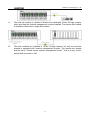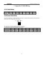
1
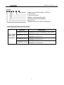
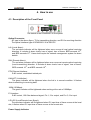
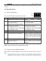
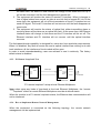
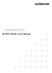
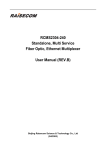
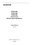
RCMS2201-30
Modular Ethernet Multiplexer
User Manual
(Rev. A)
Raisecom Technology Co., Ltd
(04/2005)
Raisecom Technology Co., Ltd
1. Cautions
Please read the following notices carefully before installing and
using the device, Raisecom does not respond to any loss that
caused by violating safety notice.
RCMS2201-30 is integrated device that has precise elements,
please avoid violent shakes and impacts, and do not
disassemble or maintain the device yourself. If it is required,
please do it under the guide of our technical staff following in
the steps of anti static. Please contact us if there is any need.
There must be grounding protection for the sake of safety; do
not disassemble the device yourself, we regard it as you waiver
your rights of repair guarantee.
1
Raisecom Technology Co., Ltd
Contents
1.
Cautions ...........................................................................................................................................1
2.
Overview ..........................................................................................................................................3
2.1.
2.2.
2.3.
3.
Parameters.......................................................................................................................................5
3.1.
3.2.
3.3.
3.4.
4.
Introduction ..............................................................................................................................3
Main Features ..........................................................................................................................3
Part Number Explanation .........................................................................................................3
E1 Interface Specification ........................................................................................................5
Fast Ethernet Interface Specification .......................................................................................5
Optical Interface Specification..................................................................................................5
Ambience .................................................................................................................................5
How to use .......................................................................................................................................6
4.1.
Description of the Front Panel..................................................................................................6
4.2.
Dip-switch Setup ......................................................................................................................7
4.2.1.
SW1 for Working Modes ..................................................................................................7
4.2.2.
Fault-Pass-Through Capability Explanation.....................................................................7
4.2.3.
E1 Remote Loop-back Test .............................................................................................8
4.2.4.
How to Implement Remote Network Management...........................................................8
5.
Installation and Test .......................................................................................................................10
5.1.
Inspect after Opening.............................................................................................................10
5.2.
Preparation before Installation ...............................................................................................10
5.3.
Installation..............................................................................................................................10
5.3.1.
Connecting the Cables...................................................................................................10
5.3.2.
Function Configuration...................................................................................................10
6.
Troubleshooting .............................................................................................................................12
7.
Appendix A Cable Making ..............................................................................................................13
A.1 E1 Cable Making..........................................................................................................................13
A.2 Ethernet Cable Making ................................................................................................................13
2
Raisecom Technology Co., Ltd
2. Overview
2.1. Introduction
RCMS2201-30 Ethernet Multiplexers are fiber-optic transmission devices for dedicated
communication networks, data communication networks, switching networks, and also for
point-to-point networks, medium-sized and small capacity networks. It can multiplex one E1
channel and one Fast Ethernet on to one fiber-optic cable, and implement the line-speed
transmission of the Ethernet data. RCMS2201-30 is featured by high integration and
complete network management functions. It can be installed into the Raisecom 3U-high
16-slot chassis, or desktop single-slot chassis, providing various network management
functions.
RCMS2201-30 Ethernet Multiplexers include the following models.
Model
Description
RCMS2201-30-M
Host-site/remote-site module, 10/100Mbps auto-sensing (RJ45), 120 Ohm balanced E1 (RJ45), multimode(DSC),
RCMS2201-30-S
Host-site/remote-site module, 10/100Mbps auto-sensing (RJ45), 120 Ohm balanced E1 (RJ45), single mode(DSC),
RCMS2201-30-S
Host-site/remote-site module, 10/100Mbps auto-sensing (RJ45), 120 Ohm balanced E1 (RJ45), single mode(DSC),
RCMS2201-30-S
Host-site/remote-site module, 10/100Mbps auto-sensing (RJ45), 120 Ohm balanced E1 (RJ45), single mode(DSC),
2.2. Main Features
z
z
z
z
z
z
z
z
Low power consumption due to extra large-scale ASIC chips; high reliability due to
4-layer PCB
Providing 1 E1 channel interface, transparent transmission mode
Providing 1 10/100Mbps auto-sensing Ethernet interface
Providing 1 optical interface, multiplexing E1 and Ethernet data together
Alarm indications of local and remote equipment
Supporting E1 link remote loop-back function, easy fault location
Supporting speed limit on both transmitting and receiving directions of Ethernet
interface, increment 32kbps
Implementation of SNMP, capable of local and remote management
2.3. Part Number Explanation
3
Raisecom Technology Co., Ltd
Example
RC MS 2 2 01 – 30 – S2
Single mode optical interface, 10-60 km
1 E1 channel
1 Ethernet interface
Modular, dual-strand fiber-optic
L2 Ethernet switching capability
Multi-service
Raisecom code (RC short for Raisecom)
Note: Equipments that can work in pairs
Host site
Remote site
RCMS2201-30-M
RCMS2201-30-M, or RCMS2101-30-FV35-M
Dual-strand
RCMS2201-30-S1
fiber-optic
equipment
RCMS2201-30-S2
RCMS2201-30-S3
RCMS2201-30-S1,
RCMS2101-30-FV35-S1
RCMS2201-30-S2
RCMS2101-30-FV35-S2
RCMS2201-30-S3
RCMS2101-30-FV35-S3
4
or
or,
or,
Raisecom Technology Co., Ltd
3. Parameters
3.1. E1 Interface Specification
Bit rate:
Line code:
Interface impedance:
Electrical characteristic:
Transfer characteristic:
Jitter Tolerance:
2048Kbps±50ppm
HDB3
120Ω balanced signal
Compliant to ITU-T G.703
Compliant to ITU-T G.823
ITU-T G.724
3.2. Fast Ethernet Interface Specification
IEEE 802.3
IEEE 802.3u
IEEE 802.1d Spanning Tree
IEEE 802.1q VLAN
Support oversized Ethernet data frame up to 1916 bytes
Working mode: 10/100M Auto-Negotiation, Auto-MDI/MDIX (manual configurable)
Flow control: IEEE802.3x and back pressure
3.3. Optical Interface Specification
Bit rate:
Fiber connector:
Transmission distance:
150Mbps
SC
Multimode dual-strand M=0 – 2 km
Single mode dual-strand S1=0-25
S3=15-120 km
3.4. Ambience
Working temperature: 0 ~ 45℃
Relative humidity: ≤ 90% (25℃)
5
km,
S2=10-60
km,
Raisecom Technology Co., Ltd
4. How to use
4.1. Description of the Front Panel
The sketch of the RCMS2201-30 front panel
Optical Connector:
SC type in the above figure, TX for transmitting direction, and RX for receiving direction
The optical interface type of RCMS2201-30 is DSC/PC.
LAL (Local Alarm):
The red alarm indicator will be lightened when error occurs at local optical receiving
direction. It includes 4 alarm levels: lose of signal, lose of frame, BER exceeds 10-3,
and BER exceeds 10-6. Users shall inquire the network management system for alarm
details.
RAL (Remote Alarm):
The red alarm indicator will be lightened when error occurs at remote optical receiving
(local transmitting) direction. It includes 4 alarm levels: lose of signal, lose of frame,
BER exceeds 10-3, and BER exceeds 10-6.
ETH Ethernet Interface:
RJ45 socket, unshielded twisted pair
LNK/ACT (Link/Action):
The green indicator will be lightened when the link is in normal condition. It flashes
when transmitting to receiving data.
100M (100Mbps):
The green indicator will be lightened when working at the rate of 100Mbps.
E1 Interface:
RJ45 socket, 120 Ohm balanced signal, Pin 1, 2 for output, and Pin 5, 6 for input
L/R LOS (Local/Remote Lose Signal):
The red alarm indicator will be lightened when E1 input loss of frame occurs at the local
site; it flashes when E1 input loss of frame occurs at the remote site.
Power Supply Indicator:
6
Raisecom Technology Co., Ltd
PWR (Power): the green indicator will be lightened when the power supply is in good
condition
4.2. Dip-switch Setup
4.2.1. SW1 for Working Modes
ON
SW1 is an 8-bit DIP-switch, as the figure on the right
Switch
1
2
3
4
5
6
7
8
OFF
12345678
OFF (default status)
ON
Enable Ethernet interface auto-sensing Disable
Ethernet
interface
auto-sensing
a) Ethernet forced 100M when a) Ethernet forced 10M when
auto-sensing disabled
auto-sensing disabled
b)Invalid when auto-sensing enabled
b) Invalid when auto-sensing enabled
a) Ethernet forced full duplex when a) Ethernet forced half duplex when
auto-negotiation disabled
auto-negotiation disabled
b) Ethernet forced full duplex when b) Ethernet forced half duplex when
auto-negotiation failed; invalid when auto-negotiation failed; invalid when
auto-negotiation success
auto-negotiation success
Reserved
Reserved
Fault Pass Through disabled
Fault Pass Through enabled
Enable MDI/MDIX auto-negotiation
Disable MDI/MDIX auto-negotiation.
Straight-through cable shall be used to
connect to Switch; crossover cable
shall be used to connect to NIC and
Routers
E1 link normal working mode
E1 link remote loop-back
Auto
recognition
of
network Forced remote network management.
management channel
Please configure as per the network
topology.
Note: The other dip-switch SW2 is a 2-bit switch, which shall be used by manufacturing
people. Users are not advised to change the default status.
4.2.2. Fault-Pass-Through Capability Explanation
When Fault-Pass-Through capability is enabled, there are 3 situations that we call it a link
fault.
1. The equipment will monitor the status of remote Ethernet interface. When it
changes to link down from link up, we take it as a link fault of remote Ethernet. At
7
Raisecom Technology Co., Ltd
the same time, the status of local module will change to link down form link up. It
will not be recovered until the fault disappears at remote site.
2. The equipment will monitor the status of remote E1 interface. When it changes to
loss of signal status from normal, we take is as a link fault of remote E1 link. At the
mean time, the equipment will cut off the transmission of local E1 interface but not
send AIS signal. The local E1 interface will not recover until the fault disappears at
remote site.
3. The equipment will monitor the status of optical link, either transmitting alarm or
receiving alarm will be taken as an optical link fault. At the mean time, the Ethernet
interface status will change to link down and the E1 interface will be cut off. The
Ethernet interface and E1 interface will not recover until the optical interface
recovers.
The fault-pass-through capability is designed for users who have particular requirements.
When it is disabled, any fault at remote site and at optical interface has nothing to do with
local interfaces; all the interfaces of local module will be open.
In order to avoid misunderstanding, users are advised to use it cautiously. The factory
default status is disabled.
4.2.3. E1 Remote Loop-back Test
Interface
Multiplex
BERT
Fiber-optic
Multiplex
Core
Core
Interface
Circuit
Circuit
E1 interface
E1 interface
Local site
Remote site
“E1 remote loop-back” setup at local Ethernet Multiplexer
Note: when setup any kinds of loop-back at the local Ethernet Multiplexer, the “remote
loop-back” switch at remote Ethernet Multiplexer must be at default status.
When the module is at E1 remote loop-back status, the Ethernet data communication will
not be interfered.
4.2.4. How to Implement Remote Network Management
When the equipment is connected as the following topology, the remote network
management can be implemented.
8
Raisecom Technology Co., Ltd
A.
The host-site module is installed in Raisecom’s dedicated 16-slot 3U-high chassis,
which also has the network management module installed. The remote-site module
is installed in Raisecom’s single slot chassis.
B.
The both modules are installed in 16-slot 3U-high chassis, but only the host-site
chassis is equipped with network management module. The remote-site module
shall be set to “forced remote network management mode”. That is to say, the 8th
switch shall be turned to ON.
9
Raisecom Technology Co., Ltd
5. Installation and Test
5.1. Inspect after Opening
Please first check if the models and part numbers are in consistence, and also check if the
equipments are damaged.
5.2. Preparation before Installation
z
z
z
z
z
Carefully read this manual
Prepare all kinds of the cable. Ensure that they are not short-circuited. Refer to
Appendix A for cable making.
Ensure the pressure of power supply is in the tolerance range, the chassis is well
connected with the ground.
Prepare the BERT and optical power meter for test of line quality.
Place the equipment at stable and secure environment. Pay attention to the
requirements of the ambience.
5.3. Installation
This module can be installed into Raisecom’s dedicated 16-slot 3U-high chassis, 4-slot
1U-high chassis, and single slot chassis. Slowly insert the module into the slot to the end,
and fasten the fixing screw tightly.
5.3.1. Connecting the Cables
z E1 Signal Interface
120 Ohm balanced signal. Connect with twisted-pair cable, Pin 1, 2 for output and Pin 5, 6
for input.
z Ethernet Interface
Connect with Cat. 5 or hyper Cat. 5 twisted-pair cables. Either straight-through or crossover
cable is OK.
z Optical Interface
Plug the tail fiber into the fiber socket to the end.
5.3.2. Function Configuration
After connecting the cables and applying the power supply, there shall not be alarms at the
10
Raisecom Technology Co., Ltd
optical interface.
If users want to configure the dip-switches, first unplug the module from the chassis and
then use a flat screw-driver to set switches.
11
Raisecom Technology Co., Ltd
6. Troubleshooting
If there is any problem during installation and operation, please try the following solutions. If
the problem still cannot be solved, please contact distributors for technical support.
The following explanations and solutions to optical and E1 LOS alarms are for the local
module. If the alarms are at the remote site, please solve them at remote site.
z Power (PWR) indicator (Green) is not ON
Answer: Power supply fails. Check whether the power supply is working properly
z LAL indicator (Red) at optical interface is ON
Answer: Loss of signal at the optical interface. Check whether the input of optical fiber is
connected properly. Users can test the optical power using optical power meter. The optical
power shall be larger than the receiving sensitivity.
z E1 sub-channel L/R LOS indicator (Red) is ON
Answer: The local E1 sub-channel receiving signal is lost. If the indicator is flashing, it
means the remote E1 sub-channel receiving signal is lost. Please check if the E1
interface is well connected.
12
Raisecom Technology Co., Ltd
7. Appendix A Cable Making
A.1 E1 Cable Making
Pin Number
Definition
1
2
3
4
5
6
7
8
OUT+
OUT-
Not Used
Not Used
IN+
IN-
Not Used
Not Used
A.2 Ethernet Cable Making
Use Cat.5 twisted-pair cable with RJ45 connector to connect this equipment. Note that the
cable shall not be longer than 100 meters.
Pin 1
Pin 8
The cable can be either straight-through or crossover.
The sequence of the RJ45 connector is as follows.
Pin Number
1
2
3
4
5
6
7
8
MDI Definition
TX+
TX-
RX+
Not Used
Not Used
RX-
Not Used
Not Used
MDI-X Definition
RX+
RX-
TX+
Not Used
Not Used
TX-
Not Used
Not Used
13
Raisecom Technology Co., Ltd
@2005 Raisecom Technology Co., Ltd.
All trademarks are the property of their respective owners.
Technical information may be subject to change without prior notification.
14