1
Instruction Manual
BCX3400
BCX3410
Important:
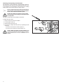
This brushcutter is shipped from the manufacturing plant without being filled with engine oil.
Fill with engine oil according to instructions before putting the brushcutter into operation!
Putting the brushcutter into operation without engine oil will result in engine damage immediately!
Congratulations! You have purchased a new MAKITA brushcutter!
We thank you for your trust and hope you will be completely
satisfied with your new brushcutter.
Brushcutters of the series BCX3400 / 3410 are included among
the lightest brushcutters with a four-stroke engine in this class.
These brushcutters are very handy, compact and multipurpose
and can be used to cut grass, weeds and brushwood.
The considerably lower fuel consumption compared to similar
brushcutters with two-stroke engines is a highly advanced step
in terms of energy consumption and emissions.
Furthermore, the four-stroke engine is an agreeably quiet
engine.
To ensure your personal safety and to guarantee optimum
operation of the brushcutter including readiness to operate,
we kindly ask you to:
Read this instruction manual carefully
before putting the brushcutter into operation for the first time and to strictly observe the safety instructions!
Nonobservance can result in serious injuries!
Proper use:
These brushcutters are intended to be used with the appropriate
and approved cutting tools for the purpose of cutting grass or
thick weeds. The brushcutter is only allowed to be used by one
person at a time and only outdoors!
Unapproved working technique:
Thicker material such as shrubs, wild plants or thickets is not
allowed to be cut using the approved cutting tools.
Unapproved users:
Persons who are not familiar with the instruction manual, children, young persons, as well as persons under the influence of
alcohol, drugs or medication, are not allowed to operate the
machine.
Table of contents
Safety instructions......................................................3
Operation....................................................................16
Explanation of symbols............................................3
General safety precautions......................................3
Personal protective equipment.................................4
Handling fuels/refueling the brushcutter...................4
Putting into operation...............................................5
Kickback (blade thrust) . ..........................................6
Working behavior and working techniques...............6
Applications for cutting tools.....................................7
Checking the reliable operating condition of the
brushcutter.............................................................16
Starting...................................................................17
2-line trimmer head..........................................................7
4-tooth star blade.............................................................7
Transport..................................................................7
Storage.....................................................................7
Maintenance.............................................................8
First aid.....................................................................8
EU Declaration of Conformity....................................8
Scope of delivery.........................................................9
Packaging....................................................................9
Main components of the brushcutter......................10
Preparations.............................................................. 11
Installing the handle............................................... 11
U-handle........................................................................11
C-handle........................................................................11
Installing the line blade and cutter guard................12
Fastening the line blade to the cutter guard..................12
Installing the cutter guard..............................................12
Installing the cutting tool.........................................12
4-tooth star blade...........................................................13
2-line trimmer head........................................................13
Refueling the brushcutter.......................................14
Operating materials/fuels...............................................14
Gasoline........................................................................14
Engine oil.......................................................................14
Refueling and filling up with engine oil..........................14
Putting on the shoulder strap.................................15
Balancing the brushcutter.......................................15
Cold starting..................................................................17
Warm starting................................................................17
Turning off the engine.............................................17
Checking and adjusting the idle speed...................18
Maintenance...............................................................19
Checking the oil level.............................................19
Tools.......................................................................19
Sharpening the 4-tooth star blade.................................19
Readjusting the line of the 2-line trimmer head.............20
Checking/replacing the line of the 2-line trimmer head20
Daily maintenance..................................................21
Cleaning the air filter......................................................21
Weekly maintenance..............................................21
Checking/replacing the spark plug................................21
Maintenance after 50 hours of operation................22
Lubricating the flexible shaft with grease.......................22
Lubricating the angular gearbox with grease.................22
Changing the engine oil.................................................22
Quarterly maintenance...........................................23
Suction head in the fuel tank.........................................23
Service after 50 tank fill-ups...................................24
Overview of maintenance and care........................24
Putting out of operation and storage......................25
Service, spare parts and guarantee.........................25
Maintenance and repairs........................................25
Spare parts.............................................................25
Guarantee..............................................................25
Troubleshooting........................................................26
Extract from the spare parts list..............................26
Technical data of the brushcutters
BCX3410/BCX3400....................................................27
Safety instructions
Primer pump
Before putting your new brushcutter into operation for the first
time, please read the following safety instructions.
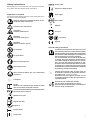
Explanation of symbols
You will notice the following symbols on the brushcutter and in
the Owner’s and Safety Manual:
Particular care and caution!
CAUTION!
Kickback (blade thrust)
DANGER! Very sharp cutting tool!
DANGER!
Beware of thrown objects!
No smoking!
No open flame!
Wear protective gloves!
Wear safety shoes!
Wear protective helmet, face, eye, and hearing
protection!
Forbidden!
NOTE!
Minimum risk. Situations that should be taken
into account when using this machine.
Start engine
Stop engine
Read the instruction manual and follow all warnings and safety instructions!
Direction of blade rotation
ON/OFF
First aid
Recycling
Sign CE
General safety precautions
To ensure correct operation, the user has to read
this instruction manual to make himself familiar
with the handling of the brushcutter. Insufficiently
informed users will risk danger to themselves as
well as others due to improper handling.
It is recommended only to lend the brushcutter
to people who have experience with brushcutters. When lending the brushcutter to someone
else, give him this Instruction Manual as well.
First-time users should ask their dealer for basic
instructions, or contact a forestry school in order
to familiarize themselves with the basic handling
of gasoline-powered brushcutting.
Children and persons under 18 years must not
be allowed to operate the brushcutter with metal cutting tools (4-tooth star blade).
Exceptions may be made for persons over 16
for training purposes under the supervision of
a qualified trainer.
Perform all work calmly and carefully.
The user must accept liability for others.
Never use the brushcutter after consumption of
alcohol, drugs or medication.
The distance between the machine and bystanders
shall be at least 15 meters!
max.
10.000 1/min
max.
9.000 1/min
Maximum tool rpm
Regular gasoline
Engine oil
Choke closed
Choke open
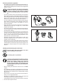
Personal protective equipment
• The clothing worn should be functional and appropriate, i.e.
it should be tight-fitting but not cause hindrance. Do not wear
either jewelry or clothing which could become entangled with
bushes or shrubs.
In order to avoid head-, eye-, hand- or foot injuries
as well as to protect your hearing, the following
protective equipment and protective clothing
must be used during operation of the brushcutter.
• It is recommended to wear a protective helmet; it is imperative
when working in forests. The protective helmet (1) should be
checked at regular intervals for damage and must be replaced
after 5 years at the latest. Use only approved protective
helmets. If you have long hair, always wear a hairnet!
1
3
• The face shield (2) of the protective helmet protects against
flying sawdust, wood chips or stone chippings. During operation of the brushcutter always wear goggles or a visor to
prevent eye injuries.
2
• Wear adequate noise protection equipment to avoid hearing
impairment (ear muffs (3), ear plugs, etc.). Octave band
analysis upon request.
• The forestry safety jacket (4) is equipped with special redcolored shoulder parts. The arms and neck should always
be protected by clothing.
• The protective trousers (5) are made from a nylon fabric with
22 layers and protects against cuts. We strongly recommend
its use. In any case, it is essential that a long pair of trousers
made of tough material be worn during operation of the
brushcutter. Do not wear short pants.
• Protective gloves (6) made of thick leather are part of the
prescribed equipment and must always be worn during
operation of the brushcutter.
• Safety shoes or boots (7) fitted with anti-skid sole, steel toe
caps and leg protection must always be used. Safety shoes
equipped with a protective layer give protection against cuts
and ensure a secure footing. Do not wear sandals or go
barefoot.
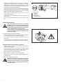
Handling fuels/refueling the brushcutter
Stop the engine and let the engine cool down
before refueling the brushcutter.
No smoking and no open flame!
Fuel may contain substances similar to solvents.
Eyes and skin should not come in contact with
mineral oil products. Always wear protective
gloves when refueling. Frequently clean and
change protective clothes. Do not breathe in fuel
vapors. Inhalation of fuel vapors can be hazardous
to your health.
• Before refueling the brushcutter make sure it is in a stable
position.
• Do not spill fuel or oil. When you have spilt fuel or oil immediately clean the brushcutter. Fuel should not come in contact
with clothes. If your clothes come in contact with fuel, change
them at once.
• Ensure that no fuel oozes into the soil (environmental protection). Use an appropriate base.
• Refueling is not allowed in closed rooms. Fuel vapors will
accumulate near the floor (explosion hazard)!
• Carefully tighten the locking screw of the fuel tank and inspect
the fuel cap at regular intervals.
4
7
5
6
• Change the place before starting the engine at least 3 meters
from the place of refueling.
• Fuel cannot be stored for an unlimited period of time. Buy
only as much as will be consumed in the near future.
• Use only approved and marked containers for the transport
and storage of fuel. Ensure children have no access to
fuel.
3 meters
Putting into operation
Never work alone. In case of emergencies, another
person must be within shouting distance. Before
beginning to work, inform the other person about
the protective devices available on the machine!
• Children and other persons must remain more than 15 meters from the working area. Keep an eye out for animals as
well.
• Before use always check that the brushcutter is safe for
operation: Make sure the cutting tool is securely installed.
The throttle must automatically return to the off position when
released, and the throttle lever lock must work properly. The
cutting tool must not turn during idling. The handles should
be clean and dry. The on/off switch must function properly.
The protective devices must be undamaged and securely
installed in the correct position (see Chapter "Operation").
Otherwise you are in danger of injury!
15 meters
• Start the brushcutter only in accordance with the instructions
(see Chapter "Operation". Do not use any other methods
for starting the engine!
• Use this brushcutter and its cutting tools only for the abovementioned uses they are intended for as specified in the
documentation.
Start the brushcutter only after complete assembly
and inspection. Operation of the machine is only
permitted after all the appropriate accessories
are attached!
The cutting tool must be equipped with its appropriate cutter guard. Never run the cutter without
this cutter guard.
• The cutting tool must not turn during idling. If necessary
adjust the idling speed (see Chapter "Operation").
• Before starting, make sure that the cutting tool has no contact
with hard objects such as branches, stones, etc.
• The engine must be switched off immediately if there are
any noticeable changes in the behavior of the equipment.
• Should the cutting tool hit stones or other hard objects,
immediately switch off the engine and inspect the cutting
tool.
• Inspect the cutting tool at frequent intervals for damage (detect
hairline cracks by means of tapping – noise test). Hairline
cracks can occur in the region of the base of the teeth after
long use. Damaged cutting tools and cutting tools with
hairline cracks must not be used any longer under any
circumstances!
• Operate the brushcutter only with the shoulder strap attached,
which is to be suitably adjusted before putting the brushcutter
into operation (see Chapter "Preparations"). It is essential
to adjust the shoulder strap according to the user’s size to
prevent fatigue during use. Never hold the cutter with one
hand during use.
• When working with the brushcutter always hold it with both
hands. Keep proper footing and balance at all times.
• Operate the brushcutter in such a manner as to avoid inhalation of the exhaust gases. Do not start or operate the
brushcutter in closed rooms (risk of gas poisoning). Carbon
monoxide is an odorless gas; breathing exhaust fumes can
kill. Work only in well-ventilated places.
• When taking a break or leaving the brushcutter unattended,
turn off the engine, make sure the cutting attachment has
stopped and set the brushcutter down in such a way that
there is no risk of injury to yourself or others.
• Never put the hot brushcutter onto dry grass or onto any
combustible materials.
• Shut off the engine during transport or when moving on to a
new location.
• Never operate the brushcutter with a faulty exhaust muffler.
Kickback (blade thrust)
When operating the brushcutter, uncontrolled
kickback may occur. This is the case whenever the
cutting tool (4-tooth star blade) comes into contact
with solid objects such as tree stumps, fence posts,
trees, solid brushwood or large stones.
In such situations, the brushcutter will be thrown
to one side at high speed and with great force
(high risk of injury).
To avoid kickbacks, observe the following:
• Clear the cutting area of any foreign objects and pay attention
to any existing planted areas and other objects.
• The cutting tool must be turning at full speed before you
begin to cut.
• An increased risk of injury exists in the darkly marked area
and especially when metal cutting tools are being used!
Working behavior and working techniques
• Before commencing cutting, the cutting tool must have reached full working speed
• Use the brushcutter only in good light and visibility. During
the winter season beware of slippery or wet areas, ice and
snow (risk of slipping). Always ensure a safe footing.
• Never cut above your shoulder height.
• Never stand on a ladder and run the brushcutter.
• Never climb up into trees to perform cutting operations with
the brushcutter.
• Never work on unstable surfaces.
Make sure the cutting area is free of foreign objects such as stones and metal items. Foreign
particles can rebound (danger of injury!), damage
the cutting tool and cause dangerous kickbacks
(see last section).
•
•
•
•
•
Work break
Transport
Refueling
Maintenance
Tool replacement
Applications for cutting tools
Use the cutting tools to perform the work described below only! Other applications are not
permitted.
2-line trimmer head
Exclusively for cutting along walls, fences, grass edges, trees,
posts, etc. (supplementing the lawn mower).
4-tooth star blade
2-line trimmer head
4-tooth star blade
For cutting grass or thick weeds. Perform this cutting work by
swinging the brush cutter evenly in half-circles from left to right
(similar to a scythe).
Transport
When transporting the equipment or moving to
another working location, the brushcutter must
be switched off in order to avoid unintentionally
starting the cutting tool.
Never drag the brushcutter behind you and never drop it (except in case of emergency). Do not
throw the brushcutter in order to load it onto the
transport vehicle!
If the brushcutter is subject to sudden jolts, it
must be checked for signs of leaking fuel (risk
of fire or explosion!).
Never transport the brushcutter with the cutting
tool still running!
• The transport safety device included in the scope of delivery
must always be fitted whenever the brushcutter is being
transported over longer distances.
• When transporting the brushcutter in the vehicle, make sure
that the brushcutter is safely secured. Empty the fuel tank
before transporting the brushcutter.
• Before shipping the brushcutter, completely empty the fuel
tank.
Storage
• The brushcutter must be safely stored in a dry room. Use
the transport safety device for metal cutting tools. Keep the
brushcutter out of reach of children.
• Following a longer storage period, have an authorized MAKITA
service center perform a thorough maintenance check and
a complete inspection of the brushcutter.
• Prior to a longer storage period of the brushcutter, the fuel
tank must be completely emptied and the carburetor run dry.
Fuels may only be stored for a limited period of time and could
cause deposits to form in the tank or in the carburetor.
• Fuel remaining in reserve canisters should be used for other
engines or be disposed of properly.
Maintenance
Always make sure that the brushcutter is in good
working order before using it. This includes, in
particular, the cutting tool, cutter guard, shoulder
strap, and fuel system (check for leaks). Particular attention must be paid to the cutting blades,
which must be correctly sharpened.
Metal cutting tools must be sharpened only at an
authorized service center!
A tool which has been improperly sharpened can
cause unbalance and thus considerable danger
of injury. Apart from this, the equipment may be
damaged due to vibrations.
When changing the cutting tool, cleaning the
brushcutter and the cutting tool, etc., it is essential
to switch off the engine and pull the spark plug
cap.
• Never straighten or weld damaged cutting tools.
• Operate the brushcutter with as little noise and pollution
as possible. In particular check the correct setting of the
carburetor.
• Clean the brushcutter at regular intervals and check that all
screws and nuts are well tightened.
• Never service or store the brushcutter near open flames!
• Always store the brushcutter in a locked storage area, with
the fuel tank completely empty and the carburetor run dry.
Keep the brushcutter out of reach of children.
Observe the accident prevention instructions
issued by the relevant trade associations and
insurance companies.
Do not make any modifications to the brushcutter! You will only be putting your own safety at
risk!
• The performance of maintenance or repair work by the user
is limited to those activities described in this instruction manual. All other work must be done by the MAKITA customer
service center.
• Use only original MAKITA spares and accessories. The
use of non-MAKITA spares, accessories, or cutting tools
increases the risk of accident. MAKITA will not accept any
liability for accidents or damage caused by the use of nonapproved cutting tools and fixing devices of cutting tools, or
accessories.
First aid
A first-aid kit should always be nearby as a
precaution in the event of an accident. Immediately replace any items taken from the first-aid
kit.
When calling for help, give the following information:
• Place of accident
• What happened
• Number of persons injured
• Nature of injuries
• Your name
Individuals with poor circulation who are exposed
to excessive vibration may experience injury to
blood vessels or the nervous system. Vibration
may cause the following symptoms to occur in
the fingers, hands or wrists: "Falling asleep"
(numbness), tingling, pain, stabbing sensation,
alteration of skin color or of the skin. If any of
these symptoms occur, see a physician.
SERVICE
EU Declaration of Conformity
Packaging
The undersigned, Shigeharu Kominami and Rainer Bergfeld, as
authorized by DOLMAR GmbH, declare that the brushcutters
of the make MAKITA,
Your MAKITA brushcutter comes in a cardboard box for proper
protection against transport damage.
Type: (366) BCX3410 and BCX3400
conforms to the basic safety and health requirements of the
applicable EU directives:
Cardboard packaging boxes are raw materials
and are therefore reusable or can be fed back
into raw material recycling systems (waste paper
utilization).
• EU Machinery Directive 98/37/EC.
• EU EMC Directive 89/336/EEC (modified by 91/263/ EEC,
92/31/EEC and 93/68/ EEC).
• Noise Emission Directive 2000/14/EC.
For proper implementation of the requirements of these EU
directives, the following standards were applied to a significant
extent: EN 11806, EN 14982, EN 61000-4-2, EN 61000-4-3.
The conformity assessment procedure 2000/14/EC was carried
out in accordance with Annex V. The measured sound power
level (Lwa) is 103 dB(A). The guaranteed sound power level
(Lwa) is 104 dB(A).
Hamburg, 2.1.2005
For DOLMAR GmbH
Shigeharu Kominami
Managing Director
Rainer Bergfeld
Managing Director
2
3
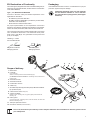
Scope of delivery
1 Brushcutter
4
5
6
1
2 U-handle
(incl. 4 fastening
washers, 2 anti-slip inserts and handle fastening cap)
(for
BCX3410 with C-handle incl. 4 fastening screws, washers and
7
handle mount)
3 Screwdriver insert
4 Screwdriver handle
5 Combination wrench
6 3 Allen key
7 Shoulder strap with hip protection pad (for BCX3410 without
hip protection pad)
8
8 2-line trimmer head (cutting tool)
9 4-tooth star blade
(cutting tool incl. mounting disk, cap, ground glider, pressure disk and fastening nut)
10 Cutter guard
11
(incl. protective strip, 4 fastening screws, nuts and washers, as well as line
blade and fastening screw)
11 Transport protection device
12 Instruction manual (without illustration)
10
9
First of all, check the scope of delivery. If one of the parts listed here is not included or is defective, please contact
your salesperson.
Main components of the brushcutter
3
4
1
5
2
6
7
9
8
11
10
12
13
22
Type plate
21
14
BCX3400
2005 123456
15
Year of manufacture
Serial number
366.000.000
20
Please specify when ordering spare parts!
16
25
17
24
23
18
19
1 Cover
14 Handle, left
2 Cap for spark plug
15 Model designation
4 Choke lever
17 Cutter guard
3 Cover for air filter
5 Muffler
6 Starter handle
7 Primer pump
8 Tank cap
9 Control cable (Bowden cable)
10 Safety locking button (throttle lever lockout)
11 Handle, right
12 Short-circuit switch ("Start / Stop")
13 Throttle lever
10
16 Main tube
18 Angular gearbox
19 4-tooth star blade (cutting tool)
20 Handle fastening cap
21 Strap holder
22 Foot
23 2-line trimmer head (cutting tool)
24 Hip protection pad (for BCX3410 not included)
25 Shoulder strap
Preparations
Before you can put the brushcutter into operation, you must
assemble and prepare it for regular operation.
The brushcutter is not allowed to be started until it
has been completely assembled and a functional
test has been carried out!
Wear protective gloves for all work on the brushcutter!
Installing the handle
Depending on whether you have decided to purchase the
BCX3400 or the BCX3410 brushcutter, your machine will be
equipped with a C-handle or with a U-handle.
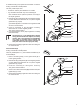
U-handle
To install the handle, lay down the brushcutter so that it is resting
on its foot in stable position.
The tool you will require is the big Allen key.
6
1 Place the anti-slip insert (1) in the handle mount (2) so that
it lines up flush with the handle mount.
2 Insert the handle as shown in the illustration.
4
3 Place the second anti-slip insert (3) on the handle (2) so
that it also lines up flush with the handle mount.
4 Place the handle fastening cap (4) on top and hold it firmly.
3
5 Insert the nuts (5) from underneath into the drilled holes of
the handle mount, hold them in place and tighten the screws
firmly (6) at the same time (do not forget the washers).
1
2
5
C-handle
To install the handle, lay down the brushcutter so that it is resting
on its foot in stable position.
The tool you will require is the medium-sized Allen key.
1 Place the handle mount (1), as shown in the illustration,
from the rear side onto the anti-slip sleeve (2) on the main
tube and hold it firmly.
2 Place the C-handle (3), as shown in the illustration, from
above onto the anti-slip sleeve (2) so that it is resting on
the handle mount.
4
3 Fasten the handle by tightening the screws (4) (do not forget
the washers).
3
2
1
11
Installing the line blade and cutter guard
On the basis of legal accident prevention regulations, the cutter guard included in the scope of delivery (and no
other cutter guard) must be installed!
To ensure your personal protection, the
brushcutter is not allowed to be put into
operation without the cutter guard under no circumstances whatsoever!
Caution: The enclosed blade, which is fastened
to the cutter guard in order to adjust the lines of
the 2-line trimmer head, is sharp!
The tools you will require are the Phillips screwdriver and the
medium-sized Allen key.
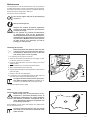
Fastening the line blade to the cutter guard
If the brushcutter is to be used with the 2-line trimmer head,
the line blade must be fastened to the cutter guard so that it
can cut the line automatically to the same length during the
readjustment operation.
1
2
1 Use the enclosed Phillips screwdriver to fasten the line
blade (1), as shown in the illustration, to the protective
strip (2).
2 Lay the cutter guard (3) down on the top side.
3 Bend the protective strip slightly with the line blade on the
inside and insert into the mounts on the bottom edge of the
cutter guard until the snap-fit closures snap into place on
both sides.
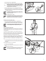
Installing the cutter guard
To install the cutter guard, lay down the brushcutter so that it is
resting on its handle in stable position.
1 Insert the four nuts (1) from the side into the provided cutouts (2) in the mount (3).
3
4
7
2 Place the cutter guard (4) on the mount so that the fastening
holes (5) in the cutter guard line up with the nuts.
3 Use four screws (6) (do not forget the washers (7)) to fasten
the cutter guard.
Use only the cutting tools included in the scope
of delivery!
Installing other cutting tools can result in an
increased risk of accidents and damage to the
machine and is therefore not permitted!
Before installing the cutting tool, you must install
the cutter guard first (see previous section).
The brushcutter can be operated using two different cutting tools:
either with the 4-tooth star blade in order to cut thick material,
such as weeds, high grass etc.; or with the 2-line trimmer head
in order to cut remaining grass along walls, fences lawn edges,
trees, posts, etc.
12
1
2
5
Installing the cutting tool
3
6
4-tooth star blade
To install the cutting tool, lay down the brushcutter so that it is
resting on its handle in stable position.
The tool you will require is the:
• Combination wrench plus screwdriver as a handle
• e.g. the medium-sized Allen key as an assembly pin
1 Place the mounting disk (1) on the gearbox shaft (2) so
that one lateral cut-out (3) lines up with the cut-out (4) in
the angular gearbox.
10
8
2 Place the winding safety device (5) on the angular gearbox
so that its lateral cut-out and the cut-out (4) in the angular
gearbox line up properly.
7
3 Insert the 4-tooth star blade (6), pressure disk (7) and
ground glider (8) after one another onto the gearbox shaft
as shown in the illustration.
4 Insert the assembly pin (9) through the mounting
disk into the cut-out of the angular gearbox.
The gearbox shaft is blocked.
5 Use the combination wrench (10) to tighten the nut firmly
(left-hand thread).
The fastening nut (10) is equipped with a plastic
locking device and must be replaced, for safety
reasons, with a new fastening nut immediately
in the case of noticeable easy movement, but
no later than after the tool has been changed 10
times (see extract from the spare parts list)!
6
5
1
3
9
4
2
6 Remove the assembly pin again and check the cutting tool
for free movement.
2-line trimmer head
To install the cutting tool, lay down the brushcutter so that it is
resting on its handle in stable position.
The tool you will require is ,e.g, the medium-sized Allen key as
an assembly pin.
1 Place the mounting disk (1) on the gearbox shaft (2) so
that the lateral drilled hole (3) lines up with the cut-out (4)
in the angular gearbox.
2 Place the winding safety device (5) on the angular gearbox
so that its lateral cut-out and the cut-out (4) in the angular
gearbox line up properly.
3 Insert the assembly pin through the mounting
disk into the cut-out of the angular gearbox.
The gearbox shaft is blocked.
4 Screw on the 2-line trimmer head (6) (left-hand thread) and
tighten firmly by hand.
5 Remove the assembly pin again and check the cutting tool
for free movement.
6
5
3
1
7
4
2
13
Refueling the brushcutter
When refueling the brushcutter, please note the following information at all times!
No smoking and no open fires!
Do not refuel in closed rooms!
Fuel vapors will accumulate on the ground (risk
of explosion)!
Fuels can contain solvent-like substances. Prevent contact of the eyes and skin with mineral oil
products. Wear gloves when refueling. Change
and clean your protective clothing more frequently. Do not inhale fuel vapors. Inhaling fuel vapors
can cause physical damage to your health.
Before refueling the brushcutter, turn off and
allow the engine to cool down.
Operating materials/fuels
The handling of operating materials/fuels requires cautious,
careful action. Refuel the brushcutter only outdoors or in wellventilated rooms.
Mineral oil products, including oils, degrease the skin. In case of repeated, longer
contact, the skin will dry up. This can result in various skin diseases. Beyond that,
allergic reactions are well known.
Contact of the eyes with oil results in irritations.
In case of eye contact, wash the affected eye
immediately with clear water. If the irritation
does not subside, a physician must be consulted
immediately!
Gasoline
The engine of the brushcutter is designed to be run with regular
gasoline with a minimum octane number of 91 RON. If that type
of fuel is not available, fuel with a higher octane number can
also be filled into the tank without damaging the engine.
Engine oil
The engine is lubricated exclusively by the engine oil (multigrade
oil of the classification SAE 10W‑30). This is why you must check
the engine oil level at a clean location before beginning to work
with the brushcutter. During this inspection, it is important to make
sure that no dirt gets onto the dipstick or into the crankcase in
order to guarantee long service life of the engine.
If, despite all precautions, dirt does get into
crankcase, the engine oil must be changed before
the engine is started.
Refueling and filling up with engine oil
The tool you will require is a clean rag.
1 Clean the area around the tank cap (1) thoroughly, so that
no dirt can get into the fuel tank (not necessary upon firsttime operation of the brushcutter).
2 Lay down the brushcutter, so that it is resting on its foot in
stable position.
3 Unscrew the tank cap and fill gasoline carefully up to the
bottom edge of the filler neck.
However, if you do spill any fuel, clean the brushcutter immediately. If fuel gets onto your clothes,
change them immediately.
14
1
4 Screw the tank cap on tightly again.
5 Clean the tank cap and the surrounding area thoroughly.
When laying down the dipstick, make sure that
it does not come into contact with dirt under no
circumstances whatsoever! Remove dirt immediately whenever necessary!
2
6 Turn the dipstick (2) out of the opening anticlockwise.
7 Upon first-time operation of the brushcutter, use a suitable
filling bottle to fill 80 cm3 of engine oil up to the bottom edge
of the filling opening (3).
3
An engine oil bottle can be used for precise dosing without spilling engine oil (see extract from
the spare parts list).
9 Turn the dipstick back in again.
Following first-time operation of the brushcutter,
the engine oil must be changed after 20 hours of
operation and not after 50 hours of operation.
Putting on the shoulder strap
1 Put on the shoulder strap as shown in the illustration.
2 Adjust the shoulder strap so that the fastening hook (1) for
the brushcutter is situated at the height of your hip bone.
The shoulder straps of the BCX3410 brushcutters
are not equipped with a hip protection pad.
Balancing the brushcutter
To balance the brushcutter, the machine must have been refueled and filled with oil (see section "Refueling the brushcutter"
in this chapter).
1
The ground clearance depends on the selected cutting tool.
When a line trimmer head is being used on level ground, the
line trimmer head should be resting on the ground lightly without
the operator touching the machine with his hands.
When the 4-tooth star blade is being used on difficult ground,
the cutting tool must be resting approx. 20 cm above the ground
without the operator touching the machine with his hands.
The tool you will require, if appropriate, is the Phillips screwdriver.
1 Hook the fastening hook (1) of the shoulder strap, depending
on the cutting tool, into one of the two holes of the strap
holder (2).
If the adjustment option is not sufficient:
2 Undo the screw (3) slightly.
3 Push the strap holder into the desired position on the main
tube.
1
4 Retighten the screw firmly.
At this point, the adjustment of the handles to suit
your body should also be carried out again.
3
2
15
Operation
Since you have performed all the preparations, the brushcutter
can now be put into operation.
The brushcutter is not allowed to be started until it has been completely assembled (see chapter "Preparations") and a
functional test has been carried out!
Observe the accident prevention regulations!
For all work performed with the brushcutter:
Wear protective gloves!
Wear safety shoes!
Wear a helmet as well as face, eye and hearing
protection!
Never work alone. In case of emergencies,
another person must be within shouting
distance. Before beginning to work, inform the other person about the protective
devices available on the machine!
The cutting tool must be equipped with the
appropriate cutter guard. Never operate the
machine without the cutter guard.
In the case of noticeable changes in the behavior
of the machine, turn off the engine immediately.
4
2
3
5
If the cutting tool comes into contact with stones
or other hard objects, turn off the engine immediately and check the cutting tool.
5
Checking the reliable operating condition of the
brushcutter
Before starting the brushcutter, always make sure that
• the cutting tool (1) fits firmly.
• upon being released, the throttle lever (2) returns to zero
position automatically.
• the safety locking button (3) is functioning.
If the safety locking button (3) is not pressed, it
must also not be possible to press the throttle
lever (2) all the way down.
• the start‑stop switch (4) (short-circuit switch) is functioning.
• the handles (5) are clean and dry.
• the cutter guard (6) has not been damaged and is firmly
installed in correct position.
6
1
16
Starting
Move at least three meters away from the refueling
location in order to start the brushcutter!
To start the brushcutter, lay it down on a sufficiently clear location
so that it is resting on its foot in stable position and the cutting
tool does not come into contact with anything else, neither with
the ground nor with other objects.
3 meters
Cold starting
If there are any starting problems, excessively stored fuel could be the reason. Fuel
can only be stored for a limited period
of time and is subject to ageing!
Therefore, purchase only as much fuel as is supposed to be consumed in a few months!
1 Push the short-circuit switch (1) upward to "START".
2 Move the choke lever (2) upward into
choke).
-position (close
3 Press the fuel pump (3) lightly approx. 7–10 times until there
are no more air bubbles to be seen in the fuel pump.
4 Hold the brushcutter firmly with one hand as shown in the
illustration.
5 Pull out the starter handle (4) slowly until you can feel a
resistance.
The piston is now located just before the upper dead-center
position.
1
6 Now pull further quickly and forcefully until the first audible
ignition occurs.
The engine will start to run for a short time.
2
Do not pull out the starter handle more than 50
cm and do not let it fly back; instead guide it back
slowly by hand.
7 Move the choke lever (2) downward into
choke).
4
-position (open
8 Pull the starter handle again until the engine starts to run.
At idle (throttle lever (6) is not operated), the cutting
tool must not rotate. However, if the cutting tool
is rotating, the idle speed must be adjusted (see
section "Checking and adjusting the idle speed").
9 By grabbing the handle and pressing the safety locking
button (5) and the throttle lever slightly (6), bring the engine
up to medium speed and maintain that speed.
Never run the brushcutter under full load immediately; instead, let the engine warm up for approx.
three to five minutes at medium speed.
3
10 With new machines, adjust the idle speed if necessary (see
section "Checking and adjusting the idle speed").
Warm starting
Start the brushcutter in warm condition, as described in the
section "Cold starting", but without opening the choke, i.e.
without putting the lever (2) into
-position.
Turning off the engine
To turn off the engine, push the short-circuit switch (1) downward to "STOP".
5
6
17
Checking and adjusting the idle speed
The carburetor of the brushcutter is equipped with a fixed jet.
This means that you will only need to adjust the idle speed, e.g.
if your machine is a new machine or the cutting tool is rotating
at idle. Make sure that the air filter is always clean!
Never run the brushcutter under full load immediately; instead, let the engine warm up for approx.
three to five minutes at medium speed.
At idle, the cutting tool must no longer rotate. If the cutting tool is rotating, the idle speed must
be readjusted.
The tool you will require is the Phillips screwdriver.
To adjust the idle speed:
1 Proper cutting tool must be installed.
2 Let the engine warm up.
3 Release the throttle lever (1).
2
4 If necessary, readjust the idle speed by regulating the idle
screw (2):
• Turn the screw inward for faster engine run.
• Turn the screw outward for slower engine run.
If the cutting tool does not stop rotating, you
must not work with the machine under no circumstances whatsoever! Contact a MAKITA service
center!
18
1
Maintenance
The maintenance work described below must be performed
regularly and properly in order to guarantee long service life of
your brushcutter and to prevent any form of damage. Warranty
claims will only be recognized in that case.
For all work on the brushcutter:
Turn off the engine and pull off the spark plug
connector!
Wear protective gloves!
Observe the accident prevention regulations
issued by the trade association and insurance
company in charge! Do not perform any structural modifications
or maintenance work on the brushcutter
extending beyond the structural modifications or
maintenance work described in this instruction
manual! Have a MAKITA service center perform
all other work for you; otherwise, you will be
putting your safety at risk!
Checking the oil level
When laying down the dipstick, make sure that
it does not come into contact with dirt under no
circumstances whatsoever! To be on the safe
side, always have a clean rag ready!
1 If necessary, let the engine cool down.
2 Clean the area around the dipstick (1) thoroughly, so that
no dirt can get into the crankcase.
3 Lay down the brushcutter, so that it is resting on its foot in
stable position.
4 Turn the dipstick out of the opening anticlockwise.
5 Wipe off the dipstick with a clean rag.
6 Dip the dipstick through the opening into the crankcase and
pull it out again.
1
2
OK
7 Read the oil level (see illustration).
8 If necessary, use a suitable filling bottle to refill engine oil
up to the bottom edge of the filler opening (2).
refill
An engine oil bottle can be used for precise dosing without spilling engine oil (available as an
accessory, see extract from the spare parts list).
9 Turn the dipstick back in again.
Tools
Sharpening the 4-tooth star blade
Metal cutting tools are only allowed to be resharpened by specialized workshop since an
improperly resharpened can cause unbalance
and therefore constitutes considerable risk of
injury. Beyond that, damage to the machine can
be caused by vibrations!
180°
Every MAKITA service center will sharpen and balance the
4‑tooth star blade for you.
In order to extend its period of use, the 4-tooth
star blade can be turned once until both blade
sides are blunt.
19
Readjusting the line of the 2-line trimmer head
The line length can be adjusted at any time with the best possible
results by tapping the line trimmer head on the ground lightly
during the mowing operation. The lengthening of the line amounts
to approx. 40 mm for each releasing operation.
The line blade cuts off projecting ends of the line automatically.
Checking/replacing the line of the 2-line trimmer head
The new nylon line must be four meters long and have a diameter of Ø 3.0 mm (order number, see extract from the spare
parts list).
To replace the line, it is advisable to dismantle the line trimmer
head first (see instructions from section "Installing the 2-line
trimmer head" in chapter "Preparations" in reverse order).
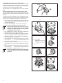
1 Press in the cover mounting clips and open the line trimmer head carefully (Caution! Inner spring presses the two
housing parts apart) (A).
2 Take the reel including the line out of the housing (B).
3 Remove remaining old pieces of line from the reel.
If there is still sufficient line on the reel, but if the
line does not adjust itself to the correct length
during the mowing operation, the line must be
wound up onto the reel again.
4 Use a paintbrush to clean the reel bottom side and the
housing and check for any signs of damage.
5 Kink the new line in the middle and insert into the partition
of the two reel guides as shown in the illustration (C, D).
A
B
C
D
E
F
G
H
6 Wind the line from the two reel guides in the direction of
the arrow tautly onto the reel (E).
7 Clamp both ends of the lines in two opposite grooves of the
reel so that the line does not slacken when the reel
is inserted into the housing (F).
8 Reinsert the reel into the bottom part of the housing and
thread both ends of the line into the line guides in the housing
(G).
9 Line up the reel according to the cut-outs in the top part of
the housing and press into the housing forcefully until
both snap-fit closures snap into place (H).
20
Uneven line lengths are cut off by the line blade
on the cutter guard automatically during regular
operation.
Daily maintenance
The following maintenance work must be carried out each time
after the brushcutter has been used.
Cleaning the air filter
If the workplace is very dusty or sandy, the
filter must be cleaned at regular intervals, due
to the fact that only a clean air filter will guarantee full engine performance. Coarse particles of dirt can destroy the engine!
Renew damaged air filters immediately!
3
2
To clean the air filter, lay down the brushcutter so that it is resting
on its foot in stable position.
1
The tool you will require is the Phillips screwdriver.
1 Unscrew the screw (1).
2 Grab the air filter cover (2) at the bottom and pull it off.
3 Push the choke lever (3) all the way up to the limit stop.
Particles of dust can no longer drop into the carburetor
now.
6
4 Remove both air filters (4, 5) and wash them off in lukewarm
alkaline soap solution with commercial-grade dish-washing
detergent.
5 Let the air filters dry completely.
6 Reinsert both air filters (first the white one (5) with the clip
facing downward on the left-hand side).
7 Place the air filter cover on the upper clips (6) first, and
then press the lower part of the cover in the direction of
the engine (you must be able to hear the cover snap into
place).
4
5
8 Retighten the screw firmly.
Weekly maintenance
The following maintenance work must be carried out once a
week during regular use.
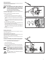
Checking/replacing the spark plug
The engine must have cooled down completely before you can
begin to the check or replace the spark plugs.
Lay down the brushcutter first so that it is resting on its foot in
stable position.
The tools you will require is the combination wrench (plus the
screwdriver as a handle) as well as a pair of insulated pliers.
Materials:Use NGK‑CMR 6A-type spark plugs only
(see extract from the spare parts list).
1 Turn out the screw (1).
2 Remove the spark plug cap (2).
3 Pull off the spark plug connector (3) from the spark plug.
4 Use the combination wrench to turn the spark plug (4) out
of the opening.
The spark plug must be replaced if its insulation
body is damaged or if its electrode is extremely
burned, soiled or oiled up, or if you can no longer see a spark during the spark test described
below.
The gap between the electrodes must be
0.7‑0.8 mm (see illustration).
1
2
4
3
0,7–0,8 mm
21
If you want to check the igniting spark (otherwise continue with
step 10):
5 Plug the spark plug connector onto the unscrewed spark
plug.
6 Use the combination wrench to make ground contact to the
cylinder.
7 Use a pair of insulated pliers to press the spark plug connector with the spark plug lightly against the combination
wrench but as far away as possible from the spark plug
hole.
8 Push the short-circuit switch (5) to "START".
9 Pull the starter cable forcefully.
If the spark plug is functioning perfectly, you must be able
to see a spark on the electrodes.
10 If necessary, use the combination wrench to screw in a new
spark plug.
11 Put the spark plug cap back on and fasten it with the
screw.
Maintenance after 50 hours of operation
The following maintenance work must be carried out after 50
hours of operation.
Lubricating the flexible shaft with grease
Do not lubricate the flexible shaft with grease
on your own. The shaft must be lubricated with
grease in one of the many MAKITA service centers!
Lubricating the angular gearbox with grease
Do not lubricate the angular gearbox with grease
on your own. The angular gearbox must be lubricated with grease in one of the many MAKITA
service centers!
The lubrication can be precisely dosed in a workshop. This
ensures that excessive amounts of grease do not cause overheating in the angular gearbox.
Changing the engine oil
Following first-time operation of the brushcutter,
the engine oil must be changed after 20 hours
of operation and then after every 50 hours of
operation.
Prevent contact of the skin with mineral oil
products. Wear gloves when changing the oil.
Change and clean your protective clothing more
frequently.
Mineral oil products, including oils, degrease
the skin. In case of repeated, longer contact, the
skin will dry up. This can result in various skin
diseases. Beyond that, allergic reactions are well
known.
Contact of the eyes with oil results in irritations. In
case of eye contact, wash the affected eye immediately with clear water. If the irritation does not subside, a
physician must be consulted immediately!
Make sure that oil does not get into the ground. Use a suitable base surface. Wipe up unintentionally spilt oil or bind
it with suitable binding agents! Dispose of old oil properly
according to environmental regulations!
22
5
The tools you will require are two clean rags and a base surface.
Materials: 80 cm3 of SAE 10W‑30 engine oil
(classification API SF)
1 Start the engine (see chapter "Putting into operation").
2 Warm up the engine for 3–5 minutes at medium speed.
3 Lay down the brushcutter on a level surface, so that it is
resting on its foot in stable position, and wait three minutes. Then the oil will have accumulated in the crankcase.
2
4 Cover the gasoline tank with a clean rag (1) as shown in
the illustration.
5 Turn the dipstick (2) out of the opening.
When laying down the dipstick, make sure that
it does not come into contact with dirt under no
circumstances whatsoever! If necessary, remove
dirt immediately with a clean rag!
3
6 Pour the old oil into a suitable container.
Prop up the brushcutter so that the oil flows out
on its own. Leave the brushcutter in that position
for a few minutes so that all of the oil can drop
out of the machine.
1
7 Clean the tank and the filler opening carefully without allowing dirt to get into the crankcase.
8 Use a suitable filling bottle to refill new engine oil up to the
bottom edge of the filler opening (3).
An engine oil bottle can be used for precise dosing without spilling engine oil (see extract from
the spare parts list).
9 Turn the dipstick back in again.
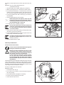
Quarterly maintenance
Suction head in the fuel tank
Prevent contact of the skin with fuels. Wear gloves
during the maintenance procedure.
Mineral oil products degrease the skin. In case
of repeated, longer contact, the skin will dry up.
This can result in various skin diseases. Beyond
that, allergic reactions are well known.
Contact of the eyes with fuels results in irritations. In case of eye contact, wash the affected
eye immediately with clear water. If the irritation
does not subside, a physician must be consulted
immediately!
The fuel required by the carburetor is filtered by means of the felt
of the suction head (2). Hardened or soiled felt filters must be
replaced; otherwise, there is the risk that insufficient amounts of
fuel will be conveyed and that the permissible maximum speed
of the engine will be exceeded as a result.
The tool you will require is a wire hook.
Materials: felt filter
1 Unscrew the tank cap (1).
2 Use a wire hook to pull the suction head (2) through the
tank cap opening.
3 Check the felt filter and replace if necessary.
4 Put the suction head back into the tank.
2
1
5 Screw the tank cap back on.
23
Service after 50 tank fill-ups
After every 50 tank fill-ups, the brushcutter must be thoroughly
serviced and checked in a MAKITA service center.
Overview of maintenance and care
The maintenance work described below must
be performed regularly and properly in order to
guarantee long service life of your brushcutter
and the full functional efficiency of the safety
devices as well as to prevent any form of damage.
Risk of accidents exists in case of nonobservance!
General
• Complete brushcutter
• Screws and nuts
• Check for damage and sealed tightness
• Check for proper function and firm fit
After each tank fill-up
• Throttle lever
• Safety locking button
• Start/Stop switch
• Check for proper function
• Check for proper function
• Check for proper function
Daily
•
•
•
•
•
•
•
•
•
•
•
•
Weekly
• Spark plug
• Muffler
• Check and replace if necessary
• Check the outlet and clean if necessary
Quarterly
• Suction head
• Gasoline tank
• Replace felt filter
• Clean
Prior to putting the
brushcutter out of
operation for a longer
period of time
• Fuel tank
• Carburetor
• Empty
• Run empty
Yearly
Complete brushcutter
Let this be checked by a MAKITA service center!
After 200 hours of operation
• Gasoline hoses
• Valve play
• Let this be replaced by a MAKITA service center!
• Let this be adjusted by a MAKITA service center!
24
Air filter
Cooling air guide
Cutting tool
Idle speed
Engine oil
Gasoline hoses
Clean
Clean
Check for damage and sharpness
Check (cutting tool must not rotate at the same time)
Check the oil level, refill oil if necessary
Check for sealed tightness; if necessary, let the hoses be replaced
by a MAKITA service center
Putting out of operation and storage
If the brushcutter is not used for more than six weeks, please
note the following recommendations:
• Perform maintenance (see chapter "Maintenance").
• Empty the fuel tank completely and run the carburetor until
dry, due to the fact that fuels can only be stored for limited
period of time and also because deposits can be formed in
the tank or carburetor.
• Use the remaining fuel in reserve canisters for other engines
or dispose of such fuel properly.
• Clean metal cutting tools and lubricate them with a small
amount of oil.
• Fill up the brushcutter with fresh fuel before putting it into
renewed operation.
Service, spare parts and guarantee
Maintenance and repairs
The maintenance and repair of modern brushcutters and
safety-related components and assemblies requires qualified
technical training and a workshop equipped with special tools
and testing devices.
We therefore recommend that you consult a MAKITA service
center for all work not described in this instruction manual.
In the case of repair work attempts performed by third persons
or by non-authorized persons, the right to claim under guarantee
shall expire.
The specialist has the required training, experience and equipment at his disposal in order to provide you with the most costeffective solution and advise you in all matters.
You will find you’re the service center nearest to you in the
enclosed list of service centers.
Spare parts
Guarantee
MAKITA guarantees the highest quality and will therefore
reimburse all costs for repair by replacement of damaged parts
resulting from material or production faults occurring within the
guarantee period after purchase. Please note that in some
countries particular guarantee conditions may exist. If you have
any questions, please contact your salesman, who is responsible
for the guarantee of the product.
Please note that we cannot accept any responsibility for damage
caused by:
• Disregard of the instruction manual.
• Non-performance of the required maintenance and
cleaning.
• Exceeding of the maximum admissible speed due to incorrect
carburetor adjustment.
• Incorrect carburetor adjustment.
• Normal wear and tear.
• Obvious overloading due to permanent exceeding of the
upper performance limits.
• Use of force, improper use, misuse or accidents.
• Overheating due to dirty cooling air supply.
• Interventions by unskilled persons or inappropriate repair
work attempts.
• Use of unsuitable spare parts or non-original MAKITA parts,
insofar as they have caused the damage.
• Use of unsuitable or excessively stored operating materials.
• Damage related to conditions arising from lease or rent
contracts.
• Damages caused by disregarding loose outer bolted connections.
Cleaning, servicing and adjustment work is not covered by
the guarantee. All repairs covered by the guarantee must be
performed by a MAKITA service center.
Reliable long-term operation, as well as the safety of your brushcutter, depends, among other things, on the quality of the spare
parts used. Use ORIGINAL MAKITA SPARE PARTS only.
Only the original parts come from the production of the machine and guarantee the highest quality in material, dimensions,
functioning and safety.
Original spare parts and accessories can be obtained from your
local dealer. He will also have the spare part lists to determine
the required spare part numbers, and will be constantly informed
about the latest improvements and innovations regarding the
spare parts being offered.
Please note also that if non-original MAKITA parts are used, this
will automatically invalidate the MAKITA product guarantee.
25
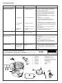
Troubleshooting
Malfunction
System
Observation
Cause/remedy
Engine does not start or
only starts very badly
• Ignition system
• Igniting spark available
• No igniting spark
• Defect in fuel supply system, compression
system, mechanical defect (service case)
• Start/Stop switch to STOP
• Defect in fuel supply system, compression
system, mechanical defect (service case)
• Spark plug connector or ignition module
defective (service case)
• Spark plug defective (see chapter "Maintenance").
• Choke lever in wrong position
• Carburetor defective (service case)
• Suction head soiled (see chapter "Maintenance")
• Fuel line kinked or interrupted (service case)
• Cylinder base gasket, radial shaft seal rings,
cylinder, valves or piston rings defective (service case)
• Spark plug does not seal up (see chapter
"Maintenance").
• Spring in the starter broken, broken parts
inside the engine (service case)
• Fuel supply
• Fuel has been filled
• Compression
system
• Inside the machine
• Outside the machine
• Mechanical
defect
Warm starting problems
• Starter unit does not
engage
Fuel in the tank and igniting spark available
Carburetor soiled (service case)
Engine starts up, but it
dies immediately
Fuel supply
Fuel in the tank
• Idle setting not correct (see chapter
"Operation").
• Suction head soiled (see chapter "Maintenance")
• Carburetor soiled (service case)
• Tank vent defective, fuel line interrupted,
cable or Start/Stop switch defective (service
case)
Insufficient power
Several systems
can be affected
simultaneously
Machine runs at idle
speed
• Air filter soiled (see chapter "Maintenance")
• Carburetor soiled, muffler clogged, exhaust
gas passage in the cylinder clogged (service
case)
Extract from the spare parts list
Use original MAKITA spare parts only. Your MAKITA service center is responsible for repairs and for the replacement of other parts.
1
2
BCX3400
BCX3410
Item MAKITA No.
Quantity Designation
1
2
3
4
5
6
7
8
9
10
1
Spark plug NGK‑CMR 6A
1
Fastening nut
12‑line trimmer head complete
1
Mowing line ø 3.0 mm x 15 meters
1
Mowing line ø 3.0 mm x 120 meters
1
Oil bottle (without oil)
1
4‑tooth star blade
1
Tank cap complete
1
Air filter
1
Air filter
367 010 995
365 060 470
366 224 010
369 224 070
369 224 072
367 210 460
362 224 140
367 601 300
374 350 120
374 350 090
3
9
10
8
4, 5
6
7
26
Technical data of the brushcutters BCX3410/BCX3400
Cubic capacity
34.5 cm3
Power rating according to ISO 8893
1.2 kW
Rated speed
7,000 rpm
Max. engine speed with one-piece metal cutting tool 10,000 rpm
1)
Max. speed of the tool spindle with one-piece metal cutting tool 7,300 rpm
Idle speed
3,000 rpm
Engaging speed
4,100 rpm
Carburetor (diaphragm carburetor)
WALBRO WYL
Ignition system
Transistor ignition
Spark plug
NGK-CMR 6A
Electrode gap
0.7-0.8 mm
Sound power level LWA av according to ISO 108842)4)5)
100.5 dB (A)4 / 100.3 dB (A)5
Sound pressure level LpA av at the workplace according to ISO 79122)4)5)
91.1 dB (A)4 / 92.4 dB (A)5
1)
Vibration acceleration ah,w according to ISO 79164)
– right handle (idle/maximum speed)
– left handle (idle/maximum speed)
BCX3400
3.5/5.4 m/s2
2.0/5.4 m/s2
Vibration acceleration ah,w according to ISO 79164)
– front handle (idle/maximum speed)
– rear handle (idle/maximum speed)
BCX3410
2.1/7.7 m/s2
2.5/11.8 m/s2
Fuel consumption according to ISO 88933)
0.458 kg/h
Specific consumption according to ISO 8893 426 g/kWh
Capacity of the fuel tank
0.65 l
Fuel
Regular gasoline
Engine oil (SAE 10W-30, classification API SF or higher)
80 cm3
Transmission ratio
1.37
Dimensions, length x width x height (without cutting tool)
1760 x 600 x 405 mm
Weight (without cutter guard, cutting tool, fuel)
MS-352 U 7.4 kg, MS-352 C 6.6 kg
3)
In case of the use of the MAKITA line trimmer head, Part No. 366 224 010, the permissible maximum speed of the line trimmer
head is not exceeded.
2)
Data takes into account the idle and maximum speed operating states equally.
3)
At max. engine power
4)
With one-piece metal cutting tool
5)
With 2-line trimmer head
1)
27
Makita Werkzeug GmbH
Postfach 70 04 20
D–22004 Hamburg
Germany
Subject to alterations
Form: 995 707 508 (8.06 GB)