1
'r$$ffi'E $E Arun
DM44
R
ffiffisi
ffi$',..'.;ti.'i'
:ffi
1-111i!.'i!ir
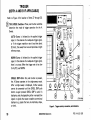
BEFORE READING-
THT.MANUALRE'RTNTEDMAR.H.,eso
PLEASE CHECK FOR CHANG E INFORMATION
AT THE REAR OF THIS MANUAL.
Rronix
COMM.IrTED TO EXCELLENCE
Tektronix, lnc.
P.O. Box 500
Beaverton, Oregon
070-2756-00
97077
INSTtrlUCTION
Serial Number
MANUAL
First Printins, MAR L979
WARRANTY
Tektronix warrants that this product is free from defects in
materials and workmanship. The warranty period is one (1) year
from the date of shipment. Tektronix will, at its option, repair or
replace the product if Tektronix determines it is defective within
the warranty period and if it is returned, freight prepaid, to a
service center designated by Tektronix.
Tektronix is not obligated to furnish service under this warranty
a.
to repair damage resulting from attempts by personnel
other than Tektronix representatives to install, repair, or
service the product;
b. to repair damage resulting from improper use or from
connecting the product to incompatible equipment;
c. if personnel other than Tektronix representatives modify
the hardware or software.
lr no lmplled warranty ol lltness lor a partlculer purpooe.
Tektronh lc not llable lor comequentlal damager.
There
o 1979 Tektronix, lnc. All rights reserved.
Contents of this publication may not be reproduced in any
form without the written permission of Tektronix, lnc.
Copyright
Products of Tektronix, lnc. and its subsidiaries are covered
by U.S. and foreign patents and/or pending patents.
are regTEKTRONIX, TEK, SCOPE-MOBILE, and fu
istered trademarks of Tektronix, lnc.
'<-:5
Printed in U.S.A. Specification and price change privileges
are reserved.
TABLE OF CONTENTS
Page
Page
LIST OF
SAFETY
ILLUSTRATIONS
SUMMARY
BEFORE OPERATING
I
iv
Y
1
.
NTRODUCTI ON
1
OPERATING SAFETY .
LINE VOLTAGE SELECTION
REGULATING RANGE SELECTION
INSTRUMENT COOLING
2
2
3
3
PRE
VERTICAL . .
4
4
.
6
DISPLAY AND CALIBRATOR
DM44 OPTION
19
LIMINARY
PRESET INSTRUMENT CONTROLS
NORMAL SWEEP DISPLAY
MAGNIF IED SWEEP DISPLAY
DELAYED SWEEP DISPLAY
ALTERNATE SWEEP DISPLAY . .
X-Y DISPLAY .
DM44 DISPLAYS AND MEASUREMENTS
ESISTANCE
VOLTS
TEMPERATURE
TEMPERATU RE ACCURACY CHECKS
I
ADJUSTMENTS AND MEASU
OPE RATI NG CONSI DE
REARPANEL...
10
13
16
LEFT SIDE PANEL
RIGHT SIDE PANEL
18
18
TR IGGER
HORIZONTAL AND POWER . .
REV A AUG 1979
.
.
SINGLE SWEEP DISPLAY
R
CONTROLS, CONNECTORS, AND INDICATORS
19
BASIC OSCI LLOSCOPE DISPLAYS
R
EMENTS
20
21
22
22
22
23
24
26
26
28
30
32
34
SIGNAL CONNECTIONS
34
34
34
35
PROBE COMPENSATION
35
GRATICULE .
G
RATIONS
.
ROUND I NG
465B/DM44 OPerators
t
.
ADJUSTMENTS AND MEASUREMENTS
,Npur coupL,NG
age
(contl
cApAc,roR
PRECHARGING .........'.36
37
,,......37
BASIC4OSB TIMING CHECK ............
37
DMrt4 TtMtNG CHECK . .
.......39
ATRIGGER INPUT COUPLING CHECK . . . . . 40
EXTERNAL HORIZONTAL GAIN CHECK ...40
MAKING PRECISION MEASUREMENTS . .. . . . 41
AC PEAK-TO-PEAK VOLTAGE . . . . . . . . . . . 41
INSTANTANEOUS DC VOLTAGE .... ..... 42
ALGEBRAIC ADDITION ..
.....43
. . . . 45
COMMON.MODE REJECTION
AMPLITUDE COMPARISON .....46
TIMEDURATION
....47
FFEOUENCY
..,....48
RISETIME
........,48
TIME DIFFERENCE BETWEEN TWO TIMERELATED PULSES .
........50
TIMECOMPARISON .....
..... 51
PHASE DIFFERENCE ....
.....52
OPERATOF'S CHECKS AND ADJUSTMENTS . .
TRACE ROTATION ADJUSTMENT
ii
.
Page
ADJUSTMENTS AND MEASUREMENTS (contl
i,1?!J;#:H'l:).ili:: liif ilf ill. : :
3l
.
5b
56
DELAyED swEEp MAGNTFTCATToN ......
Magnified Swe€p Starts After Delay . . . . . .
Triggered Delay Sweep Magnification ......
BASIC 4658 DELAYED SWEEPTIME
57
MEASUREMENTS ..........58
4658)
.... 58
Frequency (Basic 4658)
....... 60
Rise Time (Basic 4658)
.......60
Time Difference Between Repetitive Puts€s
(Basic 4658)
............61
Time Duration (Basic
Time Difference Between Two Time-Related
4658)
........63
MEASUREMENTS ..........64
Time Duration Usins DM44
.... 68
Frequency Using DM44
.......69
RiseTime Using DM44
.......69
Time Difference Between Repetitive Puls€s
Usins DM44
.....70
Time Difference Between Two Time.Retated
Pulses Using DM44
........72
+65B/DM/I4 operators
@
Pulses (Basic
DM44 DELAYED SWEEP TIME
TABLE OF CONTENTS (cont)
Page
Page
74
SPECI FICATION
VERTICAL SYSTEM
74
79
TRIGGER SYSTEM
HOR IZONTAL DEF LECTION SYSTEM
81
CALIBRATOR
Z-AXIS INPUT
SIGNAL OUTPUTS
85
86
86
87
88
88
POWER SOURCE
CATHODE.RAY TUBE
DM44
OPTIONS (cont)
.
98
INFORMATION
98
SPECIF ICATION
99
oPTroN 05 ACCESSORTES
. 100
OPERATINGINFORMATION. ...100
Installation of Video Graticule
. . 100
Operation of the SyncSeparator . . . . . 101
TriggeringtheSweep
....1O2
OPTION 05 TV SYNC SEPARATOR .
GENERAL
Vertical Operating ModesSpecial
95
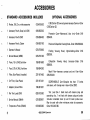
ACCESSOR r ES
STANDARD ACCESSOR I ES I NCLUDED
OPTIONAL ACCESSOR IES
@
....104
Special
. . . .105
Measurements
IDENTIFYING FIELDS, FRAMES AND LINES
rN 525/60 AND 625/50 TV SYSTEMS. . . . . 105
NTSC (CCIR System M)
. . 105
CCIR System B and Similar 625/50 Systems
OPTION 07 EXTERNAL DC OPERATION . . 107
.
96
96
96
.
96
.
97
GENERAL DESCRIPTION
..
oPTroN 04 .
oPTroN 05 .
oPTroN 07 .
. .102
...103
96
OPTIONS
oPTroNol
95
95
Considerations
Typical Operation
Selectingan lndividual Line
....
(includingPAL)
..106
SPEC|FTCAT|ON
.107
CONTROLS AND CONNECTORS
.107
OPTIONALACCESSORY
...108
OPERATINGINFORMATION. ...108
465B/DM44 Operators
ill
LIST OF ILLUSTRATIONS
Page
Figure
1
2
3
Regulating range selection and line fuse.
Vertical controls, connectors, and indicators. .
.
2
5
20
Rise time.
Time difference between two time-related
7
21
Phase
10
13
15
22
23
24
Pulse
27
29
10
Temperatu re measu rement.
31
11
Probe compensation. .
Basic 4658 timing check.
36
5
6
7
I
I
12
13
14
15
16
17
18
tv
19
17
Time differerence between two time-related
Time duration and frequency. .
Rise time.
Time difference between repetitlve pulses. . .
Time difference between two time-related
.
pulses, delayed sweep display.
38
31
32
Common-mode rejecti on.
Time duration.
47
33
4658/DM44 Operators
pulses.
59
60
62
63
pulses.
43
44
45
Algebraic addition.
57
.
29
39
nstantaneous voltage measu rement.
jitter.
Delayed sweep magnification.
26
27
28
41
I
50
53
54
55
difference
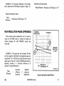
High resolution phase difference
Time duration.
Rise time.
Time difference between repetitive pulses. . .
Time difference between two time-related
25
30
DM44 timing check.
Peak-to-peak waveform voltage
49
pulses.
Display, calibrator, and DM44 controls,
connectors, and indicators
Trigger controls, connectors, and indicators.
Horizontal controls and indicators.
Horizontal and power controls and indicators.
Rear panel and left side panel controls,
connectors, and indicators
Resistance measureme nt.
Volts measurement.
4
Page
Figure
64
68
70
.
71
72
@
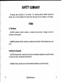
SAFETY SUMMARY
The general safety information in this summary is for operating personnel. Specific warnings and
will be found throughout the manual where they apply and do not appear in this summary.
cautions
TERMS
ln This Manual
CAUTION statements identify conditions or practices that could result in damage
to either the
instrument or other property.
WARNING statements identify conditions or practices that could result in either personal injury or
loss
of life.
As Marked on Equipment
CAUTION indicates either a personal injury hazard not immediately accessible
to property, including the instrument itself .
as
you read the marking
or a hazard
DANGER indicates a personal injury hazard immediately accessible as you read the marking.
@
4658/DM44 OPerators
SYMBOLS
As Marked on Equipment
/1
O
oeNcER
-
High voltase.
trorective ground (earth) terminal.
Power Source
This product is intended to operate from a power source that will not apply more than 250 volts rms
between the supply conductors or between either supply conductor and ground. A protective ground
connection by way of the grounding conductor in the power cord is essential for safe operation.
Grounding the Product
This product is grounded through the grounding conductor of the power cord. To avoid electrical
shock, plug the power cord into a properly wired receptacle before connecting to the product input or
output terminals. A protective ground connection by way of the grounding conductor in the power cord
is essential for safe oPeration.
va
4658/DM44 OPerators
@
Use
the Proper Power Cord
Use only the power cord and connector specified for your product.
Use only a power cord that is in good condition.
Refer cord and connector changes to qualified service personnel.
Use
the Proper Fuse
To avoid f ire hazard, use only the fuse specified for your product. Replacement fuses should be identical
in type, voltage rating, and current rating.
Do Not Operate in Explosive Atmospheres
To avoid explosion, do not operate this product in an atmosphere of explosive gases unless it has been
specifically certified for such operation.
Do Not Remove Covers or Panels
To avoid personal injury, do not remove covers or
without properly installed covers and panels.
@
panels from this product. Do not operate the product
4658/DM44 Operators
vil
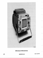
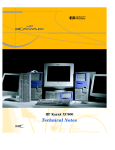
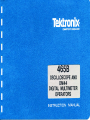
2?56-33
4658 Oscilloscope with DM44 Digital Multimeter.
vilr
4658/DM44 OPerators
REV A AUG 1979
BEFORE OPERATING
INTRODUCTION
The Tektronix 4658 Oscilloscope is a
dual-channel,
four-trace portable instrument, providing traces for two
input channels, a trigger view from an external trigger
input, and an add function. Calibrated deflection factors
from 5 millivolts/division to 5 volts/division are provided
by the dc-to-l00 MHz vertical system for the input chan'
nels and add function. Sweep trigger circuits are capable of
stable triggering over the full bandwidth capabilities of the
lncreased measurement capabilities are achieved by the
4658 when it is equipped with an optional Tektronix
DM44 Digital Multimeter. The DM44 measures 0 to 20
megohms resistance, 0 to 12OO dc volts (+ or -), and
-55o C to +150o C temperature (using a temperature
probe). Measurement values are displayed on a 3%-digit
LED readout while the oscilloscope continues normal
operation.
vertical deflection system. The horizontal deflection system
provides calibrated sweep rates from 0.5 second/division to
0.02 microsecond/division along with delayed sweep
features for accurate relative-time measurements. A X10
magnifier extends the calibrated sweep rate to 2 nano'
seconds/division. The instrument operates over a wide
variation of line voltages and frequencies with maximum
The digital multimeter and oscilloscope combine to
provide a digital readout of time difference between any
two points on the oscilloscope display. Both time measurement points are displayed simultaneously on the crt. Direct
power consumption of approximately 100 watts.
function.
@
measurement
4658/DM44 Operators
of
frequency
is provided by a
1/TIME
.
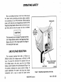
OPERATING SAFETY
Refer to the Safety Summary in the front of this manual
power source, grounding, and other safety considerations pertaining to use of the instrument. Before applying
power, verify that the Line Voltage Selector Switch and the
Regulating Range Selector Bar are both set for the line voltage being used and that the proper line fuse is installed.
for
LINE
VOLTAGE
SELECTOR
SW!TCH
This instrument may be damaged
if operated with the
Selector switch or the Regulating Range
Selector Bar set for the wrong applied line voltage or
if the wrong line fuse is used.
Line Vottage
LINE VOLTAGE SELECTION
This instrument operates from either a 1 1S-volt or a
230-volt nominal line voltage source at 48 hertz to 440
hertz. To convert the instrument for operation from one
line voltage range to the other, move the Line Voltage
Selector switch located on the right side panel (Figure 1) to
the position indicating the correct nominal voltage. ln
special applications the power cord plug may require
replacement with a type to match the power source.
4658/DM44 Operators
REGULATING RANGE
SELECTOR BAR
LINE FUSE
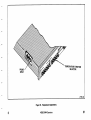
Figure
1.
2756-32
Regulating range selection and line fuse.
REV A FEB 1980
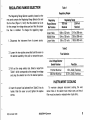
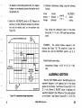
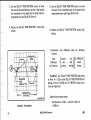
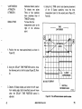
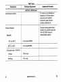
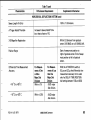
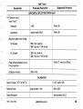
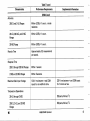
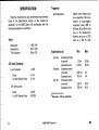
REGULATING RANGE SELECTION
Table
Regulating Ranges
The Regulating Range Selector assembly located on the
rear panel contains the Regulating Range Selector Bar and
the line fuse (Figure 1). Verify that the selector bar is set
for the average line voltage being used and that the proper
line fuse is installed. To change the regulating range:
1
Regulating
Range Selector
Bar Position
to 132 volts
to 1 26 volts
99 to 121 volts
108
104
1. Disconnect the instrument from its power
source.
216 to 250 volts
208 to 250 volts
198 to 242 volts
Table 2
2. Loosen the two captive screws that hold the cover on
the selector assembly; then pull to remove the cover.
range selector bar. Select a range from
Table 1 which corresponds to the average line voltage
and plug the selector bar into the desired position.
3. Pull out the
Fuse Selection
11S-Volt Nominal
Volt Nominal
INSTRUMENT COOLING
4.
lnsert the proper fuse (selected from Table 2) into its
holder. Push the cover on and tighten the captive
screws.
REV A AUG 1979
To maintain adequate instrument cooling, the ventilation holes in the cabinet must remain open, and the air
filter must be cleaned or replaced when it gets dirty.
4658/DM44 OPerators
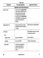
CONTROLS, CONNECTORS, AND INDICATORS
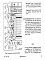
VERTICAL
Refer
to
Figure
2 for location of items 1 through
1 1.
UNCAL lndicator-A LED that lights when the
VAR VOLTS/DIV control is out of the calibrated
detent, and the vertical deflection factor is
uncalibrated.
Switches-Select the vertical deflection
factor for Channel 1 and Channel 2 in a 1'2-5 se-
@uotts/DlV
quence. VAR control must be in the calibrated detent
to obtain
a calibrated deflection factor.
POSITION Controls-Determine the vertical position
of the display on the crt. ln the X-Y mode, the
Channel 2 POSITION control moves the display
vertically (Y-axis), and the Horizontal POSITION
control moves the display horizontally (X'axis).
CH 1 OR X and CH 2 OR Y bnc Connectors-Provide
VOLTS/DlV Readouts-Consist of two light emitting
diodes (LED) for each channel, located beneath the
skirt of each VOLTS/DIV knob. One LED or the
other will light to indicate the correct deflection
factor. The 10X LED is illuminated only when a 10X
probe with a scale-switching coding-ring contact is
for application of external signals to the inputs of the
vertical amplifier. ln the X'Y mode, the signal connected to the CHl OR X connector provides hor'
izontal deflection, and the signal connected to the
CH 2 OR Y connector provides vertical deflection.
connected to the input of the oscilloscope; otherwise,
the 1x LED is illuminated.
vates the scale-factor-switching circuit whenever a
10X scale-factor-switching probe is connected.
(!r)van-Provides continuously variable uncalibrated
AC-GND-DC Switch-Selects the method used to
couple a signal to the input of the vertical amplifier.
AC position-Signals are capacitively coupled to
the vertical amplifier. The dc component of the
input signal is blocked.
deflection factors between the calibrated settings of
the VO LTS/D lV switches.
These connectors each include a coding ring that acti-
4658/DM44 Operators
@
GND position-The input of the vertical amplifier
is grounded to provide a ground reference and to
allow the input coupling capacitor to precharge.
DC position-All frequency components of the
input signal are passed to the vertical input
amplifier.
VERT MODE Switches-Select mode of operation for
vertical amplifier system. When either CHOP or ALT
mode is selected, display of any combination of CH
1, CH 2, ADD, and A TRIG VIEW (EXT ONLY) is
allowed. When all buttons are out, a single trace will
be displayed, provided that either TRIG MODE is in
AUTO or TRIG MODE is in NORM with a triggerable
signal applied to a vertical input connector. This trace
will not display intelligence and is unaffected by
ffiH
position controls.
NOTE
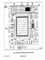
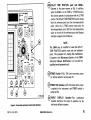
Figure
2. Vertical controls,
REV A AUG 1979
connectorc, and indicators'
Four display traces may simultaneously be observed
on the 4658 crt. Each VERT MODE push button
must be depressed and released a second time to
remove the signal from the corresponding displays.
4658/DM44 Operators
CH 1-Displays Channel 1
signals when push
button is pressed in.
A TRIG VIEW-Displays the A external
trigger
input signal when push button is pressed in and
when the A TRIGGER SOURCE switch is s'et to
EXTor EXT/I0.
ADD-Displays the algebraic sum of the Channel 1
and Channel 2 input signals when ADD push
button is pressed in. The INVERT switch in
Channel 2 allows the display to be either CH 1 plus
CH2 or CH 1 minus CH 2. TheADD capability is
useful
for common-mode reiection to remove an
20 MHz BW LIMIT (FULL BW OUT) Switch-Limits
the bandwidth of the vertical amplifier to approximately 20 MHz when pressed in. Push button must
be depressed and released a second time to regain full
1
00-MHz bandwidth operation.
20 MHz BW LIMIT lndicator-This LED is illuminated whenever the 20 MHz BW LIMIT push button
is pressed in, and bandwidth is limited to 20 MHz.
INVERT-lnverts Channel 2 display when push
pressed in. Push button must be depressed
and released a second time to present a noninverted
button is
display.
undesired signal or dc offset.
CHOP ALT: OUT-The 4658 "chops" (switches)
between two or more of the display modes at a
500-kHz rate when CHOP ALT: OUT button is
pressed in. When released, the 4658 "alternates"
between two or more of the four display modes at
the end of each trace sweep. CHOP and ALT
functions are disabled if only one VERT MODE
push button (CU 1, CH 2, ADD, or A TRIG
VIEW) is selected or if the X-Y mode is selected.
CH 2-Displays Channel 2 signals when
button is pressed in.
push
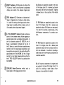
DISPLAY AND CALIBRATOR
Refer
to
Figure 3 for location of items 12 through 26.
lnternal Graticule-Eliminates parallax. Risetime and
amplitude measurement points are indicated at the
left edge of the graticule.
BEAM FINDER Switch-Compresses the display to
within the graticule area and provides a visible viewing intensity to aid in locating off-screen displays.
4658/DM44 Operators
@
T:
t
' fm)
3$rf,""".=.R
vorrsrDru
;@;
A"u)
ffi,tr Ho
l*
'@
cH2
o
/A\
tr
__--a}; tr
vorrgou
\
oo?
/A\\
\ E
\V/
o
,,-..----..
((@))
-ffi
*Lr* ?
@ E'E
M
Figure
REV A AUG 1979
,H@
tlnffi
6PoJIFlO
3.
Display, calibrator, and DM44 controls, connoctors, and indicators.
4658/DM44 OPerators
INTENSITY Control-Determines overall brightness
of the A Sweep and B Sweep crt displays. lnteracts
with B INTENSITY control on B sweep crt displays.
Focus control-Adiusts for optimum display
DM44 OPTION
60-) lnput connectors-Two banana iacks provide coM
- (blackl and + (red) inputs for dc voltage and resistance measurements-
definition.
Cef-f BRATOR Loop-A combination 3O-miiliamp
G)
\-/ current
loop and O.3-volt square wave voltage output
-
(approximately 1 kilohertz) that permits the operator
compensate voltage probes and to check oscilloscope vertical operation. lt is not intended to verify
Probe Connector-Used
to
connect
a
temperature
probe.
to
precise time-base
calibration.
SCALE ILLUM Control-Adiusts graticule
nation.
Asrrc
conrror-screwdriver contror used in
illumi-
conlunc-
tion with the FOCUS control to obtain a well-defined
display. lt does not require readjustment during
Readout-A 3%-digit
fi2)
varrays.
LED display using five 7-segment
Negative polarity indication is automatic for
negative dc voltage and temperature. No polarity
indication is displayed for positive values. A blinking
display indicates an overrang€ condition. The decimal
point location is controlled by the multimeter,s
FUNCTION and RANGE controls and by the oscillo.
TIME/D|V switch (in the TIME or 1/TIME
il::$.^
normal use of the instrument.
TRACE ROTATION Control-Screwdriver control
used to align trace with the horizontal graticule lines.
The maximum
m
sfe input in the
1.2 kilovolts dc mode
is 1200 volts.
4658/DM44 Operators
@
frequency. An illuminated 1/ms LED indicates frequency in kilohertz and an illuminated 14rs LED
indicates megahertz. Frequency in hertz is indicated when both LEDs are in a non-illuminated
RANGE-Pushbutton switches select from 0.2 volts
ranges or from 200 ohms to
to 1.2 kilovolts dc in five
20 megohms in six ranges.
state.
FUNCTION-Five pushbutton switches IVOLTS,
OHMS, TEMP (oC), 1/TlME, and TIMEI are used to
select. respective functions for measurement.
A TIME Control-Used in conjunction with
the
DELAY TIME POSITION control in the TIME
and
1/TIME functions. The A TIME control moves only
the time-measurement point while the DELAY TIME
POSITION control moves both the reference point
ms (or 1/ms) and ps (or l/tts) lndicators-Two LEDs
automatically indicate correct units of measurements.
With the TIME function selected, the units of time
difference (milliseconds or microseconds) between
the two intensified zones on the crt display is in'
dicated by illumination of either the ms or lts LED.
Seconds are indicated when both LEDs are in a
and the time-measurement point. With the timemeasurement point to the left of the reference point,
the ReadoUt indicates a negative time difference.
NOTE
non-il luminated state.
With the 1/TIME function selected, the number of
measured intervals per unit of time (milliseconds
or microseconds) is indicated by illumination of
the respective 1/ms or 14rs LED. lf the duration
of one event is being measured, the LEDs indicate
@
The DM44 may be modified to make the DELAY
TIME POSITION control move only the reference
point. The procedure for making this modification
is located in the Maintenance Section of the DM44
lnstruction Manual. Modification is to be done by
qualified service personnel only.
4658/DM44 Operators
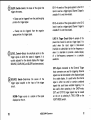
TRIGGER
(BOTH A AND B lF APPLICABLE)
Refer
to
Figure 4 for location of items 27 through 35.
TRIG MODE Switches-Three push button switches
determine the mode of trigger operation for the A
Sweep.
@ft!fl@
AUTO-Sweep is initiated by the applied trigger
signal. ln the absence of an adequate trigger signal,
or if the trigger repetition rate is less than about
t^G
OlV
:JPry-x lA
n!
2A hertz, the sweep free runs and provides a bright
flmE
I
@l ,4
;K
reference trace.
NORM-Sweep is initiated by the applied trigger
^tr
signal. ln the absence of an adequate trigger signal,
there is no trace. When the trigger rate is too low
for AUTO, use NORM.
rrE
);;.-Y*i'ffiffr
lr,ro
tEl I El
lier
SINGLE SWP-When this push button is pressed,
ffi
ffi
r,
le-ftk@
the A Sweep operates in the single-sweep mode.
After a single sweep is displayed, further sweeps
cannot be presented until the SINGL SWP push
button is again pressed. SINGL SWP is useful in
displaying and photographing either nonrepetitive
signals or signals that cause unstable conventional
displays (e.9., signals that vary in amplitude, shape,
or time).
10
Figure
4658/DM44 Operators
4.
Trigger controls, connectorc, and indicators.
REV A AUG 1979
READY lndicator-LED illuminates to indicate that
A Sweep is "armed" and will present a single-sweep
display upon receipt of an adequate trigger signal.
AC-Signals are capacitively coupled to the input
of the trigger circuit. Dc is rejected, and signals
below about 30 hertz are attenuated. Triggering
is allowed only on the ac portion of the vertical
signal.
TRIG lndicator-LED illuminates to indicate that A
Sweep is triggered and will produce a stable display.
It is useful for setting up the trigger circuits when a
trigger signal is available without a display on the crt
(for example, when using external triggers).
A TRIG HOLDOFF Control-Provides
continuous
control of time between sweeps. Allows triggering on
aperiodic signals (such as complex digital words). ln
the fully clockwise position (A ENDS A), the A
Sweep is automatically terminated at the end of
the B Sweep to provide the fastest possible sweep
repetition rate for delayed-sweep presentations and
low-repetition rate signals. ln this position Holdoff is
approximately ten times NORM. Use the A trigger
controls for most stable triggering before setting the
the A TRIG HOLDOFF control to a position other
LF REJ-Signals are capacitively coupled to the
input of the trigger circuit. Dc is rejected, and
signals below about 50 kilohertz are attentuated.
It is useful for providing a stable display of the
high-frequency components of a complex waveform.
HF REJ-Signals are capacitively coupled to the
input of the trigger circuit. Dc is blocked, and
signals below about 30 hertz and above 50 kilohertz are attenuated. lt is useful for providing a
stable display of the low-frequency components of
a complex waveform.
than NORM.
COUPLING Switch-Determines method used to
DC-AIl frequency components of a trigger signal
to the input of the trigger circuit. lt is
useful for providing a stable display of low-
couple signals to the trigger generator circuit.
frequency or low-repetition rate signals.
are coupled
@
4658/DM44 Operators
11
SLOPE Switch-Selects the slope
triggers the sweeP.
of the signal that
1-A sample of the signal applied to theCH 1
input is used as a trigger signal. Channel 2 signal is
CH
unstable
if it
is not time'related.
+: Sweep can be triggered from the positive-going
portion of
a
trigger signal.
CH
2-A
sample
of the signal applied to the CH 2
input is used as a trigger signal. Channel
-i
Sweep can be triggered
from the
negative-
unstable
if it
1 sigpal is
is not time'related.
going portion of a trigger signal.
LINE (A Trigger Circuit Only)-A sample of the
power-line sinusoid is used as a trigger signal. lt is
LEVEL Control-Selects the amplitude point on the
trigger signal at which the sweep is triggered. lt is
usually adjusted for the desired display after trigger
SOU RCE, COUP
useful when the input signal is time-related
(multiple or submultiple) to the line frequency or
when it is desirable to provide a stable display
of a linb-frequency component in a complex
waveform..
LING, and SLOPE have been selected.
EXT-Signals connected
to the External
Trigger
input connectors are used for triggering. External
SOURCE Switch-Determines the source of the
trigger signal coupled to the input of the trigger
circuit.
NORM-Trigger source is
a
sample
of the
signal
displayed on the crt.
12
4658/DM44 Operators
signals must be time'related to the displayed signal
for a stable display. lt is useful when the internal
signal is either too small or contains undesired
signals that could cause unstable triggering. lt is
also useful when operating in the CHOP mode.
EXT and EXT/I0 trigger signals may be viewed
on the crt by selecting A TRIG VIEW on the
VERT MODE switch.
@
EXT/l0 (n Trigger Circuit Only)-External
of 10.
trigger signal is attentuated by a factor
STARTS AFTER DELAY (e Trigger Circuit
Only)-B Sweep starts immediately after the delay
time selected by the DELAY TIME POSITION
39
IA
t
IIFTO
ll tri
o
T|ME
'tri
control and is independent of the B Trigger signal.
When making differential time measurements, you
must use this mode to obtain valid measurements.
On instruments equipped with a DM44 you must
use this mode to obtain valid measurements when
using the TIM E
or 1 /TlM
@"/ftrqd
E functions.
ffi-'8.
(3?) e*arrnal Trigger lnput bnc Connectors-Connect ex\-/ ternal trigger input signals for A TRIGGER and B
(DLY'D) TRIGGER circuits, when either EXT or
EXT/I0 (e Trigger only) SOURCE is
]l l*ff
selected.
^p.|Lffiffi
LFI I
to
Figures
5
and 6
for location of
-l*,-<
IH
Itr tt_t
items 36
through 47.
ry
A AND B TIME/DIV AND DELAY TIME SwitchesA TIME/DlV (clear plastic skirt) selects the sweep
rate of the A Sweep circuit for A Sweep operation
only. Also selects the basic delay time (used in
conjuction with the DELAY TIME POSITION
control) for delayed sweep operation. B TIME/DlV
REV A AUG 1979
n*
rTnc.n
@
ille-tl*llr;
-l-
HORIZONTAL AND POWER
Refer
Ei
*O
il
€ffi-m
4658/DM44 Operators
sH{ [rwll
no=or
=llk
na
ltr
€Emg
r:tiltt
,@*@'"?'@
)
Figure
5.
"ruuu
Horizontal controls and indicatorc.
13
switch (pull out and rotate to unlock) selects the
sweep rate for the B Sweep circuit for: delayed sweep
operation only. VAR control must be in the calibrated detent for calibrated A Sweep rates. When
the A TIME/DlV switch is rotated fully counter'
clockwise to the X-Y position, the horizontal (X-axis)
deflection is controlled by the Channel 1 input signal.
A AND B TIME/DIV AND DELAY TIME Switches
(used with DM44l-Operation is the same as 36a.
The
A TIME/DIV
functions.
switch also controls the TIME
indicators and decimal point location when the DM44
is in the TIME or 1lTIME Function.
POSITION Control-Positions the display horizontal'
ly for A Sweep and B Sweep, or on the X-axis (hor'
izontally) in the X-Y mode. Provides both coarse and
fine Oontrol action. Reverse the direction of rotation
to actuate fine positioning action.
X10 MAG Switch-When
pressed
in,
increases dis-
played sweep rate by a factor of 10. Extends fastest
sweep rate to 2 nanoseconds/division. The magnified
sweep expands the center division of the unmagnified
display (0.5 division either side of the center graticule
line).
14
VAR Gontrol-Provides continuously variable bweep
rates between the calibrated settings of the A TIME/
DIV switch. lt extends the slowest A Sweep rate to at
least 1.25 seconds/division. The A Sweep rate is
calibrated when the control is set fully clockwise to
the calibrated detent. lt must be in the detent posi'
tion to make accurate differential time measure'
ments. On instruments equipped with a DM44, the
VAR control must be in the detent position to make
accurate measurements in the TIME and 1/TIME
UNCAL lndicator-LED illuminates to indicate that
the A Sweep rate is uncalibrated (VAR control
of the calibrated detent).
Xl0
MAG lndicator-LED illuminates
to
is
out
indicate
that the X10 magnifier is on.
DELAY TIME POSITION Control-Selects
the
amount of delay time between the start of A Sweep
and start of B Sweep. Delay time is variable to at least
10 times the time indicated by the A TIME/DIV
switch.
4658/DM44 Operators
@
DELAY TIME POSITION (used with DlVl44)Operates in the same manner as 42a. ln addition,
when the DM44 is in the TIME or 1/TIME function,
this control operates in conjunction with the A TIME
control. The DELAY TIME POSITION control moves
both the reference point and the time-measurement
point, while the A TIME control moves only the
time-measurement point. With the time-measurement
point to the left of the reference point the Readout
indicates a negative time difference.
@n*tq@
;;,ffix lx
nr
TltE DlV
hG
I
NOTE
The DM44 may be modified to make the DELAY
TIME POSITION control move only the reference
point. The procedure for making this modification
is located in the Maintenance Section of the DM44
lnstruction Manual. Modification is to be done by
K@)*o x
tr i**-rrrfl
lq
ils
t-R l-El Fl*
rur:
^rnGGEn
f-* ---T-.
qualified seruice personnel only.
iHrM-ffiLlr,@
av
'.*
POWER Switch-PULL ON turns instrument power
on; button pushed in turns power off.
l-,il-6,ffl@
lv
lllr*u
POWER ON lndicator-LED illuminates when power
is applied to the instrument, and POWER switch is
pulled to ON.
HORIZ DISPLAY Switches-Four pushbutton
Figure
6.
Horizontal and power controls and indicators.
REV A AUG 1979
switches determine the mode
horizontal deflection system.
4658/DM44 Operators
of operation for
the
15
A-Horizontal deflection is provided by A
Sweep
at a sweep rate determined by the setting of the A
TIME/DlV switch. Only A Sweep is displayed; B
B INTENSITY Control-Determines the intensity of
the B Trace.
Sweep is inoperative.
REAR PANEL
A
INTEN-Displays the A Sweep at a rate determined by the A TIME/DlV switch. An intensified
portion can appear on the display during the B
Sweep time. This switch position provides an
indication of both the duration and position of the
B Sweep (delayed sweep) with respect to the A
Sweep (delaying sweep).
ALT-Alternates the displays between the A
INTEN and B DLY'D Sweeps. ln ALT operation,
Refer
to
Figure 7 for location
of items 48 through 57.
A +GATE-Output bnc connector provides a positivegoing pulse coincident with the A Sweep time.
g +GATE-Output bnc connector provides a positive(D
\-/ going
pulse coincident with the B Sweep time.
use TRACE SEP to vertically position B Trace; use
B INTENSITY control to adjust B Trace intensity.
B
B Sweep. The B
is determined by the B TIME/DIV
switch, with the delay time determined by the
setting of both the A TIME/DIV switch and the
DLYD-Displays only the
CH 1 VERT SIGNAL OUT-Output bnc connector
provides a sample of the signal applied to the Channel
1 preamplifier via the input connector.
Sweep rate
DELAY TIME POSITION control.
TRACE SEP Gontrol-Positions the B Sweep vertically when the ALT HORIZ DISPLAY mode is
selected.
16
EXT Z-AXIS-lnput bnc connector permits the
application of an external signal to intensity modulate the crt display. Does not affect display waveshape. Signals with fast rise time and fall time provide
the most abrupt intensity change. Signals must be
time-related to the display for a stable presentation
on the crt. The connector is useful for adding time
markers in uncalibrated modes of operation.
4658/DM44 Operators
@
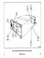
Figure
@
7.
Rear panel and left side panel controls, @nnectors, and indicators.
4658/DM44 Operators
17
Regulating Range Selector Bar-Selects the regulating
of the 4658 power supplies to match the
available power input source. lt is shown on Figure 7
in the Medium regulating range. See Table 1 for
LEFT SIDE PANEL
range
change information.
Variable Balance Controls (accessible through left
@ side
panel)-Screwdriver adiustments to set balance of
the vertical channels.
Line Fuse Holder-Contains the line fuse and the
regulating range selector. See Table 2 for change
information.
Gain Controls (accessible through left side
@ Vertical
panell-Screwdriver adjustments to set the gain of the
vertical channels.
Line Cord-Makes the connection between
the
oscilloscope and the power source. The cord may be
RIGHT SIDE PANEL
conveniently stored by wrapping around the feet on
rear panel.
Line Voltage Selector Switch-Selects either 1 15 volts
23O volts nominal line voltage. Refer to Table 1
for ranges and to Figure 1 for location of the switch.
Change the fuse to match the range selected.
or
MOD Slots-A number in either slot indicates the
instrument contains an option or other modification.
18
4658/DM44 Operators
REV
A FEB 1980
BASIC OSCI LLOSCOPE DISPLAYS
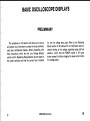
PRELIMINARY
The procedures in this section will allow you to set up
and operate your instrument to obtain the most commonly
used basic oscilloscope displays. Before proceeding with
these instructions, verify that the Line Voltage Selector
switch and the Regulating Range Selector bar are placed in
the proper positions and that the correct fuse is installed
@
for the line
voltage being used. Refer
to the Operating
Safety section of this manual for the information and pro'
cedures relating to line voltage, regulating range, and fuse
selection. Verify that the POWER switch is off (push
button pressed in) before plugging the power cord into the
line voltage socket.
4658/DM44 Operators
19
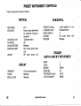
PRESET INSTRUMENT CONTROLS
Preset the instrument controls as follows:
VERTICAL
MODE
voLTs/Dtv
VERT
HORIZONTAL
TIME/DIV Switches
1
Proper setting determined A TIME/DIV VAR
HORIZ DISPLAY
by amplitude of signal to
XlO MAG
be applied
CH
detent
VOLTS/DIV VAR
AC.GND.DC
Midrange
Vertical POSITION
Not limit€d (push button
20 MH2 BW LIMIT
out)
off (push button out)
INVERT
Calibrsted
AC
POSITION
20
at 1
ms
A
Off
(push button out)
Midrange
TRIGGER
(BOTH A AND B IF APPLICABLE)
SLOPE
LEvEL
SOURCE
Fully counterclockwise COUPLING
TRIG MODE (A onlv)
Midrange
A TRIG HOLDOFF
Midranse
DISPLAY
INTENSITY
FOCUS
SCALE ILLUM
Locked together
Calibrated detent
4658/DM44 OPerators
+
o
NORM
AC
AUTO
NORM
@
NORMAL SWEEP DISPLAY
1. Preset instrument controls and pull the POWER
switch (onl. After allowing the instrument to warm
up connect a signal to the CH 1 input connector.
NOTE
vertical and horizontal POSITION controls; release
the BEAM FIND push button. Adjust LEVEL control
if
necessary.
3. Set the CH 1 VOLTS/DlV switch and the vertical
lnstrument warmup time required to meet all specifi'
cation accuracies is 20 minutes.
horizontal POSITION controls
within the graticule area.
to
4. Adjust the A Trigger LEVEL control for a
2. Adjust the INTENSITY control for the desired display brightness. lf the display is not visible with the
INTENSITY control at midrange, press the BEAM
FIND push button and hold it in while adjusting the
Channel 1 VOLTS/DlV switch to reduce the vertical
display size. Center the compressed display using the
@
and
locate the display
stable
display.
5. Set the A TIME/DlV switch for the desired number
of cycles of displayed signal; then adjust the FOCUS
control
4658/DM44 Operators
as necessary.
21
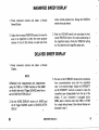
MAGNIFIED SWEEP DISPLAY
1. preset instrument controls and obtain
Sweep
Display.
a Normal
Z, Adiust the horizontal POSITION control to move the
are; to be magnified to within the center graticule
division of the crt (0.5 division on each sid; of the
center vertical graticule line). Change the TIME/DIV
switch setting as desired.
3. Push the X10 MAG switch (on) and adiust the horizontal POSITION control for precise positioning of
the magnified display. Divide the TIME/DIV settinq
by 10 to determine the magnified sweep rate.
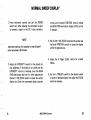
DELAYED SWEEP DISPLAY
1, Preset instrument controls and obtain
a
Normal
Display.
NOTE
3.
Differential time meaglrements and measJlements
using the T\ME or I/TIME functions of the DMtt4
are invalid wlren the B Trigger SOIJRCE swirch is
set to STARTS AFTER DELAY.
not
2. Set fte HORTZ DTSPLAY switch to A INTEN and
the B Trigger SOURCE switch to STARTS AFTER
DELAY,
22
Pull out on the B TIME/DlV knob and turn clockwise
counterclockwise stop until the intensified
zone is the desired length. Adiust the INTENSITY
and B INTENSITY controls as needed to make the
intensified zone distinguishable from the rest of the
display. lf your instrument is equipped with a
DM44, select a function other than TIME or I/TIME
from
for a single delayed sweep. Dual delayed displavs
are
discussed in step 7'
4658/DM44 Operators
@
4. Adjust the DELAY TIME POSITION control to move
the intensified zone to cover the por:tion of the dis'
play that will be displayed in delayed form.
Trigger SOURCE switch and adjust the B 'LEVEL
control for a stable display.
is equipped with a DM44, delayed
displays of two vertical channel signals can be obtained at the same time. The DM44 will indicate the time
difference between the delayed displays. To obtain
two delayed displays, select the TIME function and
set the VERT MODE to ALT, CH 1 and CH 2. The
DELAY TIME POSITION control is used to position
both delayed displays. The A TIME control positions
only the Channel 2 delayed display.
7. lf your instrument
5. SEt thE HORIZ DISPLAY SWitCh tO B DLY'D. ThC
intensified zone adjusted in steps 3 and 4 is now
displayed in delayed form. The delayed sweep rate is
indicated by the dot on the B TIME/DIV knob.
6. To obtain a delayed display with less jitter, set the B
Trigger SOURCE switch to the same position as the A
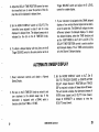
ALTERNATE SWEEP DISPLAY
1.
Preset instrument controls and obtain
a
Normal
Sweep Display.
out on the B TIME/DlV knob to unlock it and
turn clockwise to the desired sweep rate. lf the
instrument is equipped with a DM44, select a
function other than TIME or 1/TlME.
2. Pull
@
3. Set the HORIZ DISPLAY switch to ALT. Set B
(DLY'D) TR IGGER SOURCE to STARTS AFTER
DELAY. Adjust Channel 1 POSITION and TRACE
SEP as required to display A Sweep above B Sweep.
This will provide a display that alternates between A
INTEN trace (upper) and B DLY'D trace (lower).
Adjust B INTENSITY as necessary to view the
B DLY'D trace (lower).
4658/DM44 OPerators
23
of B Sweep may
be changed by adjusting
the DELAY TIME POSITION control.
4. The start
6. The display now contains a second intensified zone
on the A INTEN trace (upper) and a second signal,
which may be partially or fully superimposed, on the
B DLY'D trace (lower).
is equipped with a DM44 and a time
difference (or period) measurement is desired, select
the TIME function and adjust the A TIME control to
move the time-measurement point with respect to the
5. lf the instrument
7. The DELAY TIME POSITION control will change
the position of both delayed displays (reference and
time measurement), while the A TIME control will
position only the second (measurement point)
delayed display.
reference point.
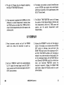
X-Y DISPLAY
1. Preset instrument controls and pull the POWER
switch (on). Allow the instrument to warm up.
2. Set the A TIME/DlV switch fully counterclockwise
to X-Y. Apply the vertical signal to the CH 2 OR Y
input connector and the horizontal signal to the CH 1
OR X input connector.
24
3. Advance the INTENSITY control until the display is
visible. lf the display is not visible with the INTEN'
SITY control at midrange, press and hold in the
BEAM FIND push button while adjusting the CH 1
and CH 2 VOLTS/DlV switches until the display is
reduced in size, both vertically and horizontally. Cen'
ter the compressed display with the PoslTloN controls (Channel 2 POSITION control for vertical movement, and horizontal POSITION control for
horizontal movement). Release the BEAM FIND
push button. Adjust the FOCUS control for a welldefined display.
4658/DM44 Operators
@
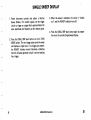
SINGLE SWEEP DISPLAY
1, Prsset instrument controls and obtain
a Normal
Sw€ep Display. For random signals, set the trigger
circuit to trigger on a signal that is approximately the
same amplitude and frequency as the random signal.
2.
e
3. When the sweep is complete, the circuit is "locked
out", and the READY indicator turns off.
SWP push button again to prepare
the circuit for another Single Sweep Display.
4. Press the SINGL
the SINGL SWP push button on the A TRIG
MODE switch. The next trigger pulse starts the sweep
and displays a single trace. lf no triggers are present,
the READY indicator should illuminate, indicating
that the A Sweep generator circuit is set and waiting
for a trigger.
Press
4658/DM44 Operators
25
DM44 DISPLAYS AND MEASUREMENTS
Except for the TIME and 1/TIME functions, the
DM44
is independently usable whenever the oscilloscope is turned
on. The TIME and 1/TIME functions are discussed in the
Adjustments and Measurements section
under the subsection titled DM44 Delayed Sweep Time
Measurements. Additional use of the DM44 in the TIME
and 1/TIME functions
is describ€d in
of this manual Displays section under the
the Basic Oscilloscope
Delayed Sweep Display
subsection.
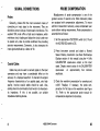
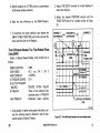
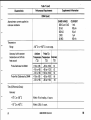
RESISTANCE
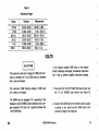
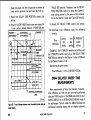
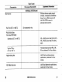
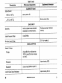
3. Observe the readout. Press the next
lower-value
RANGE push buttons as necessary to obtain a proper
readout (see Table 3).
if it is operating in the
mode (OHMS function selected) and a
The DM44 may be damaged
resistance
voltage exceeding 120 volts rms is applied between
the + and COM leads.
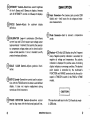
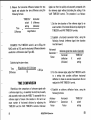
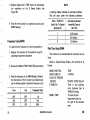
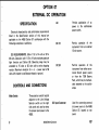
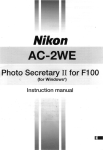
1. press the OHMS FUNCTION push button and the
20 MO RANGE push button (see Figure 8).
2. Connect
resistance.
26
the + and COM leads to the unknown
NOTE
When
the DM44 r's connected to any
unknown
resistance, a blinking readout for any RANGE value
selected indicates an overrange condition. The next
higher RANGE value should be selected.
lf no resistance is connected to the DM44 and any
RANGE value is selected, a normal blinking readout
occuni.
4658/DM44 Operators
@
--
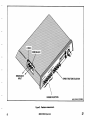
RESISTANCE
INPUT
OHMS FUNCTION SELECTOR
RANGE SELECTION
Figure
@
8. Resistan@
(465/DM-O-2 )2039-9
maasurement.
4658/DM44 Operators
27
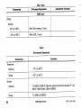
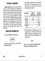
Table 3
Resistancr Ranges
Range
20 MQ
2Mo
200 ko
20 ko
2kO
200 s,
Readout
Measurement
20.00-02.00
2.000-0.200
200.0-20.00
20.00-02.00
2.000-0.200
200.0-000.0
20 Mo-2 Mo
2 MQ-200 kO
200 ko-20 ko
20 ko-2 ko
2 kO-200 Q
200 rl-0 s,
VOLTS
lf the readout exceeds
The maximum
sfe input
voltage is !1200 volts (dc +
peak ac) between the + and COM inputs or between
the + input and chasis.
The maximum COM floating voltage
is !500 volts
(dc + peak ac) to chassr.s.
The DM44 may be damaged if it is operating in the
resistance mode (OHMS function selected) and a voltage exceeding 120 volts rms is applied between the
+ and COM leads.
28
1200 volts or the readout
blinks (indicating overrange), immediately disconnect
the + lead to prevent possible instrument
1.
damage.
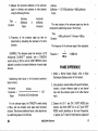
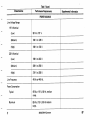
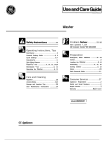
Press both the VOLTS FUNCTION push button and
the 1.2 kV RANGE push button (see Figure g).
2. Connect the COM lead to the reference point (usually
a ground or test point) and the HIGH lead to the
unknown voltage to be measured.
465B/DM44 Operators
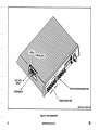
@
,#$
VOLTAGE
INPUT
...;;:
VOLTS FUNCTION
SE
LECTOR
REFERENCE
RANGE SELECTION
(465/DM-O-3)2039-10
Figure
@
9. Volts
measurement.
4658/DM44 (iperators
29
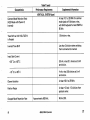
3. Observe the readout. Press the next lower-value
RANGE push buttons as necessary to obtain a proper
Table 4
Voltage Ranges
readout (see Table 4).
NOTE
while in the
is 0000,
readout
the
20 volt to 1.2 kitovott ranges,
AIso'
blink'
may
elements
readout
and individual
noise picked up by the meter leads may increase the
tf no voltage is applied to the DM44
readout white
in
the 0.2 volt and 2 volt
Range
Readout
1.2 kV
1.200-0.200
200.0-020.0
20.000-02.00
2.000-0.200
0.200-0.000
v
20v
200
2V
200 mV
ranges'
Measurement
1.2
kV-200 V
200
v-20 v
20v-2v
2V-O.2V
v-0 v
0.2
A blinking
readout for any RANGE value selected
indicates an overrange condition. The next higher
RANGE value should be selected.
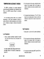
TEMPERATURE
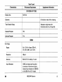
1. Press the TEMP ('C) FUNCTION push button
(see
Figure 10).
nfe voltage on the mdasurement
is !100 volts (dc + peak ac) above chassts
The maximum
surface
ground.
The sensor tip is fragile and may break if dropped or
subiected to excessive stress. Force exerted on the
sensor tip should not exceed 20 pounds.
exceeds -5f C or +150o C, imme'
probe to prevent probe damage'
the
remove
diately
tf
30
the readout
2. Apply the temperature probe to the device whose
temperature is being measured. Refer to the probe's
lnstruction Manual for specific instructions regarding
probe use.
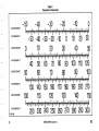
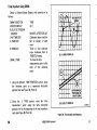
3. Observe the readout. Refer to Table 5 to convert the
readout from degrees Celsius to degrees Fahrenheit.
4658/DM44 OPerators
@
TEMPERATURE FUNCTION
SELECTOR
2756-tO
Figure 10. Temperature measuroment.
@
4658/DM44 Operators
31
TEM PERATURE ACCURACY CHECKS
The DM44 is calibrated to its original temperature
probe and should be recalibrated to any replacement probe.
Refer to the DM44 lnstruction Manual for calibration
tip into the water, avoiding the sides or
bottom of the container. Wait for the readout to
stabilize, indicating the probe has reached the water
2. Put the probe
temperature.
procedures.
3. The readout should be between
For the following accuracy checks, use an accurate
thermometer to verify water temperature. Anything in
solution affects the melting temperature, and the boiling
point is affected by changes in altitude and barometric
-2o
C
to
2o C. There
should be ice remaining after the test to verify that
inserting the probe did not raise the water temperature.
pressure.
High Temperature
1. Bring water to a slow boil (to prevent splattering).
Low Temperature
1. Allow a container (preferably insulated) of crushed
ice to melt until there are only a few pieces of ice
remaining.
2. Put the probe tip into the water, avoiding the sides or
bottom of the container. Wait for the readout to
stabilize, indicating the probe has reached the water
temperature.
To prevent posible probe damage, ensure that only
the sealed portion
Figure l0).
32
of
the probe is immerced
(see
3. The readout should be between g8o
C and 102o C
for
fresh water at sea level.
4658/DM44 Operators
@
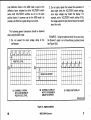
Table 5
Tempe ratu re Conversion
CENTIGRADE
-50
FAHRENHEIT
-30
-40
- 50
CENTIGRADE
-40 -30 -20
10
-10
10 20
-10
20
40
30
FAHRENHEIT
40
CENTIGRADE
50
60
FAHRENHEIT
130
CENTIGRADE
FAHRENHEIT
1738-35
@
60
100
140
230
BO
90
100
150 160 170 180 190
120
240
50
110
90
70
110
220
70
130
120
100
200 210
140
250 260 270 280 290
4658/DM44 Operators
30
1s0
300
33
ADJUSTMENTS AND MEASUREMENTS
This .section provides the procedures and information
you will need to make precision measurements with the
4658 an.d the DM44 (if your instrument is equipped with
this option). lt is divided into three subsections. The first
contains basic operating information and techniques that
should be considered before attempting any measurements.
The second subsection is comprised of a series of operator's
checks and adjustments which, when performed, should
verify instrument operation and ensure optimum measurement accuracies. The final subsection details the procedures,
formulas, and examples required to make the various types
of precision measurements with your instrument.
OPERATING CONSIDERATIONS
GROUNDING
GRATICULE
The graticule is internally marked on the faceplate of the
crt to provide accurate measurements without parallax. lt is
marked
with eight vertical and ten
horizontal major
divisions. ln addition, each maior division is divided into
five minor divisions. The vertical deflection and horizontal
timing are calibrated to the graticule so that accurate mea'
surements can be made directly from the crt.
34
The most reliable signal measurements are made when
the 4658 and the unit under test are connected together by
a common reference (ground) lead in addition to the signal
lead or probe. The ground strap on the probe provides the
best grounding method. Also, you can connect a ground
lead from the unit under test to the chassis ground banana
jack located on the lower left portion of the instrument
front
panel.
4658/DM44 Operators
@
PROBE COMPENSATION
Misadjustment of probe compensation is one of
SIGNAL CONNECTIONS
Probes
the
of operator error. Most attenuator probes
are equipped with compensation adjustments. To ensure
greatest sources
Generally. probes offer the most convenient means of
connecting an input signal to the instrument. They are
shielded to prevent pickup of electrostatic interference. The
supplied 10X probe offers a high input impedance, which
minimizes circuit loading and allows the circuit under test
to operate very close to normal conditions thus providing
accurate measurements. Conversely, it also attenuates the
input signal amplitude by a factor of 10.
optimum measurement accuracy, always compensate your
probe before making measurements. Probe compensation
accompl ished as fol lows
is
:
1. Set the appropriate VOLTS/DlV switch to 0.1 V and
the AC-GND-DC switch to DC.
2. Preset instrument controls and obtain
a
Normal
Sweep Display presentation (see Basic Oscilloscope
Displays section of this manual) using the ell kHz
CALIBRATOR square-wave output as the input
signal. Display several cycles of the CALIBRATOR
Coaxial Cables
Cables may also be used
connectors and may have
to connect signals to the input
a considerable effect on the
of a displayed waveform. To maintain the original
frequency characteristics of an applied signal, only highquality, low-loss coaxial cables should be used. Also,
cabling should be terminated at both ends in its characteristic impedance. lf this is not possible, use suitable
square-wave
at
approximately
four
divisions
amplitude.
accuracy
i
m
@
pedance-match
i
n
g devices.
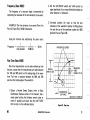
3. Check the waveform presentation for overshoot and
rolloff. Readjust, if necessary, the probe compensation for flat tops on the waveforms (see Figure
1 1 ). Refer to the appropriate probe manual for
compensation adjustment instructions.
4658/DM44 Operators
35
plifier input. The precharging network also provides
a mea-
sure of protection to the external circuitry by reducing the
current levels that can be drawn from the external circuitry
CORRECT
duri ng capacitor charging.
FLAT
OVER COMPENSATED
(OVERSHOOT}
The following procedure should be used whenever the
probe tip is connected to a signal source having a different
dc level than that previously applied, especially if the dc
level difference is more than 10 times the VOLTS/DIV
setti ng:
UNDER COtvlPENSATED
(ROLLOFF}
1. Set the AC-GND-DC switch to GND before connecting the probe tip to a signal source.
2. Touch the probe
tip to the oscilloscope
chassis
ground.
465
3. Wait several seconds for the input coupling capacitor
Figure 11. Probe eompensation.
to discharge.
INPUT COUPLING CAPACITOR
PRECHARGING
4.
Connect the probe tip to the signal source.
for the input coupling capacitor
ln the GND position, the input signal is connected to
ground through a one-megohm resistor to form a pre'
5. Wait several seconds
to charge.
charging network. This network allows the input coupling
capacitor to charge to the average dc'voltage level of the
signal applied to the probe. Thus, any large voltage transients accidentally generated will not be applied to the am'
6. Set the AC-GND-DC switch to AC. The display will
remain on the screen, and the ac component of the
signal can be measured in the normal manner.
36
4658/DM44 OPerators
@
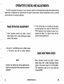
OPERATOR'S CHECKS AND ADJUSTMENTS
To verify the operation and accuracy of your instrument, perform the following checks and adjustments before making a
lf adiustments are required beyond the scope of these operator's checks and adjustments, refer to a qualified
service technician for instrument calibration.
measurement.
TRACE ROTATION ADJUSTMENT
1. Preset instrument controls and obtain
a
Normal
Sweep Display (refer to Basic Oscilloscope Displays
section of this manual).
3. lf the resulting trace is not parallel with the center
horizontal graticule line, rotate the TRACE ROTATION adjustment screw, located just below the crt
graticule (see Figure 3), to align the trace with the
center horizontal graticule line.
2. Set the CH 1 AC-GND-DC switch to GND to display
a f ree-running trace with no vertical deflection.
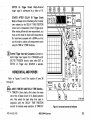
BASIC 4658 TIMING CHECK
1. Preset instrument controls and obtain
NOTE
Normally, the resulting trace will be parallal with the
center horizontal graticule line and should not require
adjustment.
@
a Normal
Sweep Display (refer to Basic Oscilloscope Displays
section in this manual) using the =1 kHz CALIBRA-
TOR square-wave output as the input signal (see
following NOTE).
4658/DM44 Operators
37
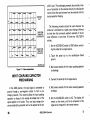
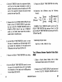
graticule division (see Figure 12]l. Use the horizontal
NOTE
POSITION control
Attach a bnc-to-binding post adapter to the A TRIG'
GER external input iack. Using a test lead with an
attigator ctip at each end, connect one alligator clip to
the adapter and the other clip to the xl kHz CAL'
I.BRATOR output.
to
align the waveform with
graticule lines.
2. Set A TRIGGER SOURCE switch to EXT.
3. Depress VERT MODE A TRIG VIEW push button
and release CH 1 VERT MODE push button.
4. Adjust A TRIGGER SLOPE and LEVEL controls to
stablize and center the display.
3 DIVTSIONS
300 mV
NOTE
The CALTBRATOR signal is not intended to be used
as a precise timing reference. lt is employed in the
fotlowing steps only as a convenient means of demonstrating basic instru ment operation.
1
SOUARE-WAVE PER
DIVISION= lkHz|NPUT
SIGNAL
2756-t3
5. Verify a display of approximately one square wave
(first positive edge to second positive edge) per
38
4658/DM44 operators
Figure
12.
Basic 4658 timing check.
@
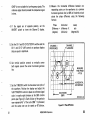
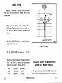
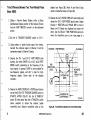
5. Usins the DM44 A TIME control, move the timemeasurement point to the leading edge of the next
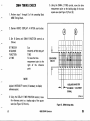
DM44 TIMING CHECK
1. perform steps
r
through 5 of the preceding
Basic
square wave (see Figure 13' Point B)'
4658 Timing Check.
2. Depress HORIZ DISPLAY
A INTEN push button.
3. Set B Sweep and DM44 FUNCTION controls
as
follows:
TIME/DIV
SOURCE
F UNCTION
A TIME
B
5 ps
B
STARTS AFTER DELAY
TIM E
To move the timemeasurement point to the
right of the reference
point
I
3 DIVISIONS
300 mV
TI
NOTE
l
Adjust B INTENSITY control, if nrcesary, to display
reference point.
SOUARE.WAVE PER
DIVISION= lkHz|NPUT
SIGNAL
4. Using the DELAY TIME POSITION control, move
the reference point to a leading edge of the square
wave (see Figure 13, Point A).
@
2756-L4
Figure
4658/DM44 Operators
13. DM44 timing check.
39
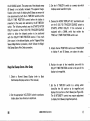
6. Observe
the DM44 readout. lt
approximately
1
should indicate
.000 ms.
the A TIME control to position the timemeasurement point to each suceeding square'wave
7. Using
leading edge, observe that respective readouts indicate
approximately 2.000 ms, 3.000 ms, 4,000 ms, etc.
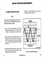
A TRIGGER INPUT COUPLING CHECK
1. Perform steps 1 through 5
of the
4.
Move the A TRIGGER COUPLING lever to HF REJ.
The display should show rounding off of the rising
and falling edges of the square'wave input. Highfrequency filtering causes exclusion of components
making up the square edges.
5. Move the A TRIGGER COUPLING lever to DC and
adjust the A TRIGGER SLOPE LEVEL control, if
necessary, to align the bottom edges of the square
wave with the graticule center line. Display should
show all ac and dc components of the input signal.
preceding Basic
4658 Timins Check.
EXTERNAL HORIZONTAL GAIN CHECK
2. With the A TRIGGER COUPLING lever set to AC,
verify that the dc component of input is rejected.
The display should show an almost flat top and
bottom of the square wave, with centering around the
graticule center line. Three graticule divisions denotes
a 300-mV signal (set vertical VOLTS/DlV
Basic
2. Set the A TIME/DlV control to X'Y.
3. Set the CH 1 VOLTS/DIV switch to 50 m.
3. Move the A TRIGGER COUPLING lever to LF REJ
and verify rejection of the 1-kHz square-wave input.
Display should show differentiated spikes as a result
40
of the preceding
4658 Timing Check.
as
required).
of filtering circuits.
1. Perform steps 1 through 5
4. The crt display should show two dots with a horizontal separation of approximately 5.75 to 6.25
divisions.
4658/DM44 Operators
@
MAKING PRECISION MEASUREMENTS
4.
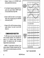
AC PEAK-TO-PEAK VOLTAGE
Measure
the vertical deflection from peak to
to Point B).
peak
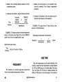
(see Figure 14, Point A
NOTE
Either channel input connector may be used for the
signal input. lJse the VERT MODE switch to select
the appropriate channel for display.
1.
Obtain
a
Normal Sweep Display (refer
POSITION TO
CENTERLINE
to Basic
Oscilloscope Displays section of this manual, using
the signal to be measured as the channel input.
the VAR VOLTS/DlV control is in the
calibrated detent, vertically position the display so
that the negative peak of the waveform coincides
with one of the horizontal graticule lines (see Figure
14, Point A).
2. Ensuring that
MEASURE AMPLITUDE
FROM A TO B
(1
3. Horizontally position the display so that one of the
positive peaks coincides with the center vertical
Figure
graticule line (see Figure 14, Point Bl.
@
465B/DM44 Operators
738-16)2038-1 5
14. Peak-to-peak waveform voltage.
41
INSTANTANEOUS DC VOLTAGE
NOTE
lf the amplitude measurement is critical or if the
trace is thick as a result of hum and/or noise on the
signal, a more accurate measurement can be obtained
by measuring from the top of a peak to the top of a
valley. This will eliminate trace thickness from the
measurement.
NOTE
Either channel input connector may be used for the
signal input. Use the VERT MODE switch to select
the appropriate channel for display.
Normal Sweep Display (refer to Basic
of this manual). Make
sure the VAR VOLTS/DIV control is in the cal-
1. Obtain
5. Calculate
the
peak-to-peak voltage, using the
following formula:
Volts
{p-p)
=
ibrated detent.
vertical
deflection
factor
X
VO LTS/D IV
switch
2. Determine the polarity of the voltage to
setting
as
Also include the attenuation factor of the probe
being used, if it is not a 10X scale-factor-switching
be measured
follows:
a.
probe.
Set the AC-GND-DC switch to GND and vertically position the baseline to the center graticule
line of the crt.
EXAMPLE: The measured peak-to-peak vertical deflection is 4.6 divisions (see Figure 14) with a VOLTS/DIV
switch setting of 0.5, using a 10X scale-factor-switching
probe.
Substituting the given values:
Volts (p-p) = 4.6 divisions X 0.5 V/divisions = 2.3 volts
42
a
Oscilloscope Displays section
b. Set the AC-GND-DC switch to DC. lf the waveform moves above the center line of the crt, the
voltage is positive. lf the waveform moves below
the center line of the crt, the voltage is negative.
3. Set the AC-GND-DC switch to GND and position the
baseline to a convenient reference line. For example,
if the voltage to be measured is positive, then position
4658/DM44 Operators
@
I
the baseline to the bottom graticule line. lf a negative
voltage is to be measured, position the baseline to the
top graticule line.
4. Switch the AC-GND-DC switch to DC. Measure the
divisions of vertical deflection between the reference
line and the desired point on the waveform (see
Figure 15).
5. Calculate instantaneous voltage, using the following
formula:
lnstan-
vertical
taneous=distanceXPolarltY
X
Voltage (oivisions) (+ or -)
VO LTS/D IV
switch
setting
Also include the attenuation factor of the probe
being used, if it is not a 10X scale-factor-switching
probe.
EGATIVE REFERENCE LINE
EXAMPLE: The vertical distance measured is 4.6
divisions (see Figure 15). The waveform is above the
reference line, and the VOLTS/DIV switch is set to 2.
Substituting the given values:
lnstantaneous Voltage
= 4.6 X (+11 X 2 V =
+9.2
volts.
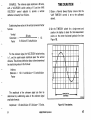
ALGEBRAIC ADDITION
Figure
@
15. lnstantaneous voltage measurement.
with the VERT MoDE switch in the ADD position, the
waveform displayed is the algebraic sum of the signals
applied to the Channel 1 and Channel 2 inputs (CH 1 + CH
2l.. lf the Channel 2 INVERT switch is de.pressed, the
waveform displayed is the difference of the signals applied
to the Channel 1 and Channel 2 inputs (CH 1 - CH 2). The
4658/DM44 Operators
43
total deflection factor in the ADD mode is equal to the
deflection factor indicated by either VOLTS/DlV switch
(when both VOLTS/DIV switches are set to the same
position factor). A common use for the ADD mode is to
provide a dc offset for a signal riding on a dc level.
2. Do not apply
signals that exceed the equivalent of
about eight times the VOLTS/DlV switch settings,
since large voltages may distort the display. For
example, with a VOLTS/DlV switch setting of 0.5,
the voltage applied to that channel should not exceed
about four volts.
The following general precautions should be observed
when using the ADD mode:
1.
Do not
exceed
the input voltage rating of
oscilloscope.
EXAMPLE: Using the graticule center line as zero volts,
the
the Channel 1 signal is on a three-division, positive dc
level
(see Figure 16A).
NEGATIVE OFFSET
(A} CHANNEL
1 SIGNAL
WITH 3 DIVISIONS OF
POSITIVE DC LEVEL.
(B} CHANNEL 2 DISPLAY
wrTH 3 DIVISIONS OF
(C} RESULTANT DISPLAY
NEGATIVE OFFSET.
465/DM-O-1
Figure 16. Algebraic addition.
44
4658/DM44 Operators
@
1. Multiply 3
divisions
by the
VOLTS/DlV switch
setting to determine the dc-level value.
CH 1 SIGNAL
WITH UNWANTED
LINE FREOUENCY
2. To the Channel 2 input apply a negative dc level (or a
positive level, using the Channel 2 INVERT switch)
Iq'
COMPONENT
9q
of the value determined (see Figure 168).
3. Depress the ADD push button to put the resultant
display within the operating range of the POSITION
controls (see Figure 16C).
CH 2 SIGNAL
FROM LINE
FREOUENCY
SOURCE
(INVERTED)
(A} CH
4.
I
AND CH 2 SIGNALS,
Release the CH 1 and CH2 push buttons to eliminate
possible confusion,
display only.
if
you wish to view the ADD
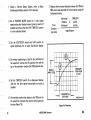
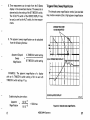
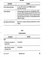
COMMON-MODE REJECTION
SIGNAL WITH
The ADD mode can also be used to display signals that
contain undesirable components. These undesirable com-
ponents can be eliminated through common-mode
rejection. The precautions given under the preceding
LINE FREOUENCY
COMPONENT
CANCELED
OUT
Algebraic Addition should be observed.
EXAMPLE: The signal applied to the Channel 1 input
contains unwanted line frequency components (see Figure
17A). To remove the undesired components use the following procedure:
@
IB) RESULTANT SIGNAL.
I 738-19
Figure 17. Common-mode rejection.
4658/DM44 Operators
45
1. Connect a line frequency signal
to the Channel
2
1.
Set the amplitude of the reference signal to an exact
number of vertical divisions by adjusting the VOLTS/
DIV and VAR VOLTS/DlV controls.
2.
Establish a vertical conversion factor, using the
following formula (reference signal amplitude must
input.
2. Set the VERT MODE ALT switch out and the
Channel 2 INVERT switch in. Adiust the
be known:
Channel 2 VOLTS/DlV and VAR controls so that the
Channel 2 display is about the same amplitude as the
undesired portion
of the Channel 1 display (see
Vertical
Conversion
Factor
Figure 17A).
reference signal amplitude (volts)
vertical
def
lection X
VOLTS/D IV
switch
(divisions)
3. Depress the ADD push button. Slightly readiust the
Channel 2 VAR VOLTS/DlV control for maximum
cancellation of the undesired signal component (see
Figure 1781.
setting
3. For the unknown signal, adjust the VOLTS/DIV
switch to a setting that provides sufficient vertical
deflection tci make an accurate measurement. Do not
readjust the VAR VOLTS/DlV control.
4. Establish an arbitrary deflection factor, using
AMPLITUDE COMPARISON
Repetitious amplitude comparisons of unknown signals
with a reference signal (e.9., on an assembly line test) may
be easily and accurately made using the 4658. To accomplish this, a reference signal of known amplitude is first set
to an exact number of vertical divisions by adjusting the
VOLTS/DlV and the VAR VOLTS/DlV controls.
Unknown signals can then be quickly and accurately compared with the reference signal without disturbing the
setting of the vAR voLTS/DlV control. The procedure is
as
46
the
following formula:
Arbitrary Vertical
lection = Conversion X
Factor
Factor
Def
5.
VOLTS/DlV
switch
setting
Measure the vertical deflection of the unknown signal
in divisions and calculate
following formula:
follows:
4658/DM44 Operators
its amplitude using
Unknown Arbitrary
Signal = Def lection X
Amplitude Factor
the
Vertical
Deflection
(divisions)
@
EXAMPLE: The reference signal amplitude is 30 volts,
with a VOLTS/DIV switch setting of 5 and the VAR
VOLTSiDIV control adjusted to provide a vertical
deflection of exactly four
divisions.
TIME DURATION
a Normal Sweep Display (ensure that the
VAR TIME/DIV control is set to the calibrated
1. Obtain
detent).
Substituting these values in the vertical conversion factor
formula:
Vertical
30 volts
Conversion =
Factor
4divisionsXSvolts/divisaon
=
1.5
2. Set the TIME/DIV switch for a single event and
'position the display to place the time'measurement
points on the center horizontal graticule line (see
Figure 1 8).
For the unknown signal, the VOLTS/DlV switch setting
peak'to-peak amplitude spans five vertical
divisions. The arbitrary deflection factor is then determined
is 1, and the
by substituting values in the formula:
Arbitray
Deflection
=
1.5 X 1 volt/division = 1.5 volts/division
Factor
The amplitude of the unknown signal can then be
determined by substituting values in the unknown signal
I 73E-20
amplitude formula:
Amplitude = 1.5 volts/division X 5 divisions = 7.5 volts.
@
4658/DM44 OPerators
Figure 18. Time duration.
47
3. Measure the horizontal distance between the
time-
measurement points
1. Measure the time duration of one waveform cycle
using the preceding Time Duration measurement
procedure.
4. Calculate time duration,
Time
using the following formula:
horizontal
distance X
(divisionsl
Duration
.
TIME/DIV
switch
2. Calculate the reciprocal of the time duration value to
determine the frequency of the waveform.
setting
magnification
EXAMPLE: The signal shown
duration of 16.6 milliseconds.
in Figure 18 has a time
EXAMPLE: The distance between the time-measurement
points is 8.3 divisions (see Figure 18), and the
switch is set to 2 ms. No magnification is used.
TIME/DIV
Calculating the reciprocal of time duration:
' = time
- duration +'
16.6 ms
Frequencv
=6oHz
-=
Substitute the given values:
-TiT: = 8.3 div X 2 ms/div = 16.6 ms
uural|0n
RISE TIME
FREeuENcy
.*:,ff":'l'#:1ilfr11"J#ilTj#}Tfi:::il:*;
rhe rrequency or a recurrent sisnarcan be determined llJii""11r3:L?i:"FJ",,1|!',:"li:.tJl"T;:sj"l',"r";
from its time duration measurement as follows:
9096 and 1096 points on the trailing edge of the waveform,
48
4658/DM44 Operators
@
1.
Obtain
a
Normal Sweep Display (refer
to Basic
Oscilloscope Displays section of this manual).
7. Measure the horizontal distance between the 107o and
90% points and calculate the time duration using the
following formula:
SLOPE control to *. Use a sweep
speed setting that displays several cycles or events (if
possible) and ensure that the VAR TIME/DlV control
is in the calibrated detent.
2. Set
horizontal
A TRIGGER
distance
(divisions)
Time
Duration
=
X
TIM E/D IV
switch
setting
magnification
(rise time)
3. Set the VOLTS/DIV switch and VAR control (or
signal amplitude) for an exact five-division display.
4. Set vertical positioning so that the zero reference of
the waveform touches the 0% graticule line and the
top of the waveform touches the IOOYo graticule line.
MEASURE
SIGNAL
AMPLITUDE
TIME FROM
ATOB
5. Set the TIME/DlV switch for a single-event display,
with the rise time spread horizontally as much as
possible.
6. Horizontally position the display so the 10% point
on
graticule
vertical
the
second
intersects
waveform
the
line (see Figure 19).
@
4658/DM44 OPerators
HORIZONTAL
DISTANCE
Figure
19.
465/DM-O-13
Rise time.
49
EXAMPLE: The horizontal distance between the 10%
and 90% points is 5 divisions (see Figure 19) and the TIME/
DIV switch is set to 1 ls. No magnification is us€d.
frequency signals and ALT is best for high-fre{uency
signals. Center each of the displays vertically (see
Figure 20)'
NOTE
Substituting the given values:
Rise
time
Sdivisions X
=
1
psldivision
lnput signals must be time related for a
= 5lts
( measu
TIME DIFFERENCE BETWEEN TWO
TIME-RELATED PULSES
1. Obtain
a
Normal Sweep Display (refer
to
2. Set the
CHANNEL 1 (REFERENCE)
Basic
Oscilloscope Displays section of this manual). Ensure
that the VAR TIME/DlV control is in the calibrated
detent.
stable
reable ) d isp I ay.
CHANNEL 2
1(X)
9ll
50%
AMPLITUDE
LEVEL
MEASURE
TIME FROM
ATOB
A TRIGGER SOURCE switch to CH 1.
3. Using probes or cables with equal time delays connect
the reference signal to Channel 1 and the comparison
signal to Channel 2 inputs.
4. Depress the CH 1 and CH 2 VERT MODE push
buttons. Use either CHOP (in) or ALT (out) VERT
MODE switch depending on the frequency of input
signals. ln general, CHOP is more suitable for low50
HORIZONTAL
-.->t I DIFFERENCE !+
I
Figure
4658/DM44 Operators
465/DM-0-14
20. Time difference between two time-related
pulses.
@
the horizontal difference between the two
signals and calculate the time difference using the
5. Measure
following formula:
TIME/DlV horizontal
switch X difference
setting (divisions)
Time =
magnification
Difference
signals can then be quickly and accurately compared with
the reference signal without disturbing the setting of the
VAR TIME/DIV control. The procedure is as follows:
1. Set the time duration of the reference signal to
an
exact number of horizontal divisions by adiusting the
TIME/DlV and VAR TIME/DlV controls.
2. Establish a horizontal conversion factor, using the
following formula (reference signal time duration
EXAMPLE: The TIME/DlV switch is set to 50ps, the
MAG switch to Xl0, and the horizontal difference between
waveforms is 4.5 divisions (see Figure 20).
must be known):
Horizontal
Conversion =
Factor
4.5 divisions
= 22.5
tts
X
TIME/D IV
switch
setting
3. For the unknown signal, adjust the TIME/DlV switch
to a setting that provides sufficient horizontal
deflection to make an accurate measurement. Do not
readjust the VAR TIME/DlV control.
TIME COMPARISON
Repetitious time comparisons of unknown signals with
a reference signal (e.9., on assembly line test) may be easily
and accurately made using the 4658. To accomplish this a
reference signal of known time duration is first set to an
exact number of horizontal divisions by adjusting the
TIME/DlV and the VAR TIME/DlV controls. Unknown
@
horizontal
def lection
(divisions)
Substituting the given values:
Time _ 50 psldivision I
10
Difference
reference signal time duration (seconds)
4. Establish an arbitrary deflection factor, using
the
following formula:
Factor
4658/DM44 Operators
TIME/D IV
Horizontal
Arbitrary
Deflection
=
Conversion
Factor
X
switch
setting
51
5. Measure the horizontal deflection of the unknown Arbitrary
signal in divisions and calculate its time duration Deflection = 1.37 X 50ps/division = 68.5ps/division
formula:
Arbitrary
Deflection "X
-;;;;r*
using the following
lme =
Duration
I
Factor
horizontal
deflection
Ai;;.,"*i
The time duration of the unknown signal can then be
computed by substituting values in the formula:
Time
unknown signal can then be
determined by calculating the reciprocal of its time
6. Frequency
of the
Duration
duration.
=
1. Obtain
Substituting these values
in the horizontal conversion
factor
Factor
2,19ms
8 divisions X 0.2 ms/divisions
=
52
7 divisions = 480 gs
4809s
calculated:
=2.083kHz
PHASE DIFFERENCE
a
Normal Sweep Display (refer
to
Basic
oscilloscope Displays section ofthismanual)'
2. using probes or coaxial cables with equal time delays,
connect a known reference signal to one channel
input and the unknown signal to the other channel
1.37
input.
For the unknown signal, the TIME/DIV switch setting
is 50ls, and one complete cycle spans seven horizontal
divisions. The arbitrary deflection factor is then determined
by substituting values in the
'l
-
divisions.
Conversion =
x
The frequency of the unknown signal is then
EXAMPLE: The refergnce signal time duration is 2.19 Freouencv
milliseconds (2.19X10⁻³ seconds), with a TIME/DIV
switch setting of 0.2 ms and the VAR TIME/DIV control
adiusted to provide a horizontal deflection of exactly eight
formula:
Horizontal
68'5 gs/division
formula:
4658/DM44
3. Depress the CH 1 and CH 2 VERT MODE push
buttons. Use either CHOP (in) orALT (outl VEBT
MODE switch depending on the input frequencies.
ln general, ALT is best for high.frequency signals and
OperatoB
@
-
CHOP is more suitable for low-frequency signals. The
reference signal should precede the comparison signal
in time.
8. Measure
the horizontal difference
between cor-
responding points on the waveforms at a common
horizontal graticule line (at 50% of risetime) and cal-
culate the phase difference using the following
formula:
4.
lt the signals are of opposite polarity, set the
INVERT switch to invert the Channel 2 display.
5. Set the CH 1 and CH 2 VOLTS/DlV switches and the
CH 1 and CH 2 VAR controls to produce displays
Phase
Difference
=
(degrees)
CHANNEL
horizontal
sweep
difference X
(divisions)
rate
(degrees/div)
CHANNEL 2
(LAGGING)
1
(REFERENCE)
that are equal in amplitude.
6. Use vertical position controls to vertically center
both signals around the center horizontal graticule
line.
MEASURE
TIME FROM
ATOB
7. Set the TIME/DlV switch to show about one cycle of
the waveform. Position the display and adjust the
VAR TIME/DlV control to place one reference signal
cycle in exactly eight divisions at the 50% risetime
points (see Figure 21!'. Each division of the graticule
now represents 45o of the cycle {360' + I divisions)
and the sweep rate can be stated as 45oldivision.
@
4658/DM44 Operators
HORIZONTAL
DIFFERENCE
I
^ A.r r.^r^rt^
|
465/DM-0-1s
Figure
21.
Phase difference.
53
EXAMPLE: The horizontal difference is 0.6 division
with a sweep rate of 4s"/division as shown in Figure 21.
Substituting the given values:
phase Difference = 6 divisions
x 4.5./division
= 2zo
Substituting the given values:
^,lly
L,lTrerence
= 0.6 divisions X
4s'ldivision = 27o
HIGH RESOLUTION PHASE DIFFERENCE
CHANNEL
1
CHANNEL 2
(REFERENCE)
More accurate phase measurements can be made by
using the X10 MAG mode to increase the sweep rate
without changing the VAR TIME/DlV control
(see
Figure 22l-.
MEASURE
TIME FROM
EXAMPLE: lf the sweep rate were increased 10 times
with the magnifier (X10 MAG), the magnified sweep rate
would be 45 * 10 = 4.5o/division. Figure 22 shows the same
signals used in Figure 21, but the X10 MAG push button is
depressed, resulting in a horizontal difference of 6
divisions. The phase difference is:
phase
Difference
54
=
horizontal
magnified
(divisions)
(degrees/div)
difference x
ATOB
I
l*
HORIZONTAL
DIFFERENCE
I
-
465/DM-O-16
sweep rate
4658/DM44 Operators
Figure 22. High resolution phase differenc€.
@
PULSE JITTER
MEASURE
TIME FROM
ATOB
Pulse jitter is displayed as the slight horizontal movement of a pulse and includes the inherent jitter of the
delayed sweep.
1. Obtain
a
Normal Sweep Display (refer
to
Basic
Oscilloscope Displays section of this manual). Ensure
that the vAR TIME/DlV switch is in the calibrated
detent.
JITTER
2. Set the B TIME/DIV switch to intensify the full
I 7 38-34
rising portion of the pulse.
Figure
3. SEt thE HORIZ DISPLAY SWitCh tO
4. Referring to
Pulse
jitter.
B DLY'D.
Figure 23, measure the distance between
Point A and Point B in divisions and calculate the
pulse jitter time using the following formula:
Pulse horizontal B TIME/DIV
Jitter = differenceX switch
(divisions) setting
Time
@
23.
DELAYED SWEEP MAGNIFICATION
USING ALT SWEEP DISPLAY
The delayed sweep features of the 4658 can be used to
provide higher apparent magnification than is provided by
4658/DM44 Operators
55
the
Xl0 MAG switch. The
sweep rate of the delayed sweep
(B Sweep) is not actually increased. The apparent magnification is the result of delaying the B Sweep an amount of
time determined by both the A TIME/DlV switch and the
DELAY TIME POSITION control before the display is
at the sweep rate selected by the B TIME/DlV
switch. The following method uses the STARTS AFTER
DELAY position of the B (DLY'D) TRIGGER SOURCE
switch to allow the delayed portion to be positioned
with the DELAY TIME POSITION control. lf too much
jitter occurs in the delayed display, use the Triggered Delay
presented
Sweep Magnification procedure, which follows the Magnified Sweep Starts After Delay procedure.
a
Normal Sweep Display (refer
4. Depress the HORIZ DISPLAY
ALT push button and
set the B (DLY'D) TRIGGER SOURCE switch to
STARTS AFTER DELAY. lf the instrument is
equipped with a DM44, verify that neither the
TIME nor 1/TIME FUNCTION switch
5.
is set.
Adjust channel POSITION control and TRACE SEP
to display .A and B Sweeps, one above the other.
the start o, ,n. intensified zone with the
DELAY TIME POSITION control to the part of the
display to be magnified.
6. Position
Magnified Sweep Starts After Delay
1. Obtain
3. Set the A TIME/DIV switch to a sweep rate which
displays several waveform cycles.
to Basic
Oscilloscope Displays section of this manual).
2. Set the appropriate VOLTS/DlV switch to produce a
display about two divisions in amplitude.
56
7. Set the B TIME/DIV switch to a setting which
intensifies the full portion to be magnified and
displays that portion as the B Sweep (see Figure24l.
The B INTENSITY control may require adjustment
to display the B Sweep (magnified portion).
4658/DM44 OPerators
@
8. Time measurement can be made
from the B Sweep
display in the conventional manner. The sweep rate is
determined by the setting of the B TIME/DlV switch.
The B DLY'D switch of the HORIZ DISPLAY may
Triggered Delay Sweep Magnification
The delayed sweep magnification method just described
may produce excessive jitter at high apparent magnification
be used, as well as the ALT switch. for time measurements.
INTENSIFIED ZONE
TO BE MAGNIFIED
9. The apparent sweep magnification can be calculated
from the following formula:
Apparent Delayed
Sweep
Magnf ication
A TIME/DlV switch setting
B
TIME/DlV switch setting
(A) A INTENSIFIED DISPLAY
EXAMPLE: The apparent magnification of a display
with an A TIME/DIV switch setting of 0.1 ms and a B
TIME/DlV switch setting of 1 ,.rs.
(B) B DELAYED DISPLAY
Substituting the given values:
Apparent
Magnif ication
@
=
1 X 10⁻⁴
1
X 10-6
= 100 times
Figure
4658/DM44 Operators
24. Delayed
2756-25
srveep magnification.
57
ranses. Operatins the B Sweep in a trissered mode
provides
a more stable display, since the delayed display is triggered
at the same point each time.
1. Perform steps 1 through 6 of the preceding
Masniried sweep starts Arter Deray piocedu'el
BASIC 4658 DELAYED SWEEP TiME
MEASUREMENTS
-o_perating
the 4658
oscilloscope
in ALT
HORIZ
lltj.n:.,il:"i'ITlj:3';fi':ttil;}f::1;.
than attained with A HORIZ DISPLAY.
accuracy
2. Set the B (DLY',D) TRIGGER SOURCE switch to the
same position as the A TRIGGER SOURCE switch'
3. Adiust the B LEVEL controt.so the.intensified zone Time Duration (Basic 4668)
on the trace is stable, (lf an intensified zone cannot
be obtained, see step 4).
1. Obtain
4. lnability to intensify the desired portion indicates
that the signal does not meet the triggering
requirethe
the
ments. lf the condition cannot b€ remedied with
B Sweep triggering conttols or by increasing
display amplitude, you should lower the VOLTS/
DIV setting. set B (DLY,D) TRIGGER SOURCE
switch to EXT, and trigger the B Sweep externally'
5E
made and magnification factors
4658/oMil4
Normal Sweep Display (refur
to
Basic
button.
measurement, set the B TIME/
fastest
to
the
sweep that provides a usable
switch
DIV
2' For the most accurate
are
calculated in the same mannir described in the
Magnified Sweep Starts After Delay procedure.
5. Measurements are
a
Oscilloscope Displays section of this manual). Ensure
that the VAR TIME/DIV switch is in the calibrated
detent. Depress either the ALT HORIZ DISPLAY
push button or the A INTEN HORIZ DISPLAY push
(visible) intensified zone. Vertically position the A
Sw€ep display to place the time measurement points
on the center horizontal graticule line (see Figure 25).
Operato.s
@
-
3. Use the DELAY TIME POSITION control to
move
the start of the intensified zone so that it iust touches
the intersection of the signal and the center horizon'
ta! graticule line (see Figure 25, Point Al.
4. Record the DELAY TIME POSITION control
dial
setting.
5. Use the DELAY TIME POSITION control to move
the start of the intensified zone to the second time
measurement point (see Figure 25, Point B).
6. Record the DELAY TIME POSITION control
dial
setting.
7. Determine
time difference using the
following
formula:
INTENSIFIED
Time
Difference
(or Duration)
fsecond
=
I
ai.t
I
settins
,lfi,]
f
',#,i,if "J
EXAMPLE: The DELAY TIME POSITION dial settins
MEASURE
TIME
FROM A TO
!l<-
at Point A is 1.20 and the DELAY TIME POSITION dial
setting at Point B is 9.53 with A TIME/DIV switch set to
B
2 ms (see Figure 25).
xORIzoNTAL
DrsrANcE
465/DM-O-9
Substituting the given values:
Time Duration = (9.53
Figure
25. Time duration.
= 16.66
4658/DM44 OPerators
ms
-
1.2O1
(2) = 8.33 X 2
Frequency (Basic
4658)
2. Set the VOLTS/DIV switch and VAR control (or
rhe rrequency or a recurrent
by
EXAMPLE: rhe time duration of one event (point A
to
sisnar is determined
computing the reciprocal of the time duration of one event.
Point B, Figure 25) is 16.66
milliseconds.
:llffil
t
il:l[:i;t
lt€n
exact rive-division disprav on
*t:l!H;:l:
#::'.T:'J
"i'd'J'l*""*?,,.ttx""""n::
line and the
top of the waveform touches the
IOO%
graticule line (see Figure 26).
Using the formula and substituting the given value:
Frequencv
=
time
=
duration
1
16.66 ms
=
6oHz
Rise Time (Basic 4658)
Rise time measurements use the same methods as time
duration, except that the measurements are made between
the 10% and 90% points on the leading edge of the waveform. Falf time is measured between the 9oo/o and 1Oo/o
points on the trailing edge of the waveform.
1. Obtain
a
Normal Sweep Display (refer
to
Basic
Oscilloscope Displays section of this manual). Use a
sweep speed setting that displays several cycles or
events if possible and ensure that the VAR TIME/
DIV control is in the calibrated detent.
60
MEASURE
SIGNAL
AMPLITUDE
4658/DM44 Operators
TIME
FROM A TO
HORIZONTAL
I
I
DISTANCE
Figure
26.
B
(465/DM-O-1
1
)2039-29
Rise time.
@
4.
Set the A
TIME/DlV switch for a single-event display,
with the rise time spread horizontally as much
possible. Horizontally position the display so the 10%
point of the waveform intersects the second vertical
graticule line (see Figure 26).
5.
9. Record the DELAY TIME POSITION dial
Depress either the A INTEN HORIZ DISPLAY push
button or the ALT HORIZ DISPLAY push button.
Set the B (DLY,D} TRIGGER SOURCE SWitCh tO
STARTS AFTER DELAY. SCt thc B TIME/DIV
switch to the fastest sweep speed that provides a
usable (visible) intensified zone.
6. Use the DELAY TIME POSITION control to move
the start of intensified zone (left'hand edge) until it
10. Determine
the DELAY TIME POSITION dial
setting.
time difference using the
following
formula:
A
Rise
Time
=
Difference = Tlme
flME/Dtvl
switch
settins
I
J
EXAMPLE: The A TIME/DlV switch is setto 1 ps. The
DELAY TIME POSITION dial setting at Point A is 2.50
and the DELAY TIME POSITION dial setting at Point B is
7.50 (see Figure 26).
Substituting the given values:
Rise Time = (7.50
just touches the intersection of the signal and the
10% graticule line (see Figure 26, Point Al.
7. Record
settrng.
as
-
2.501 (1) = 5 ps
Time Difference Between Repetitive Pulses (Basic
4658)
1. Obtain
a
Normal Sweep Display (refer
to
Basic
Oscilloscope Displays section of this manual).
8. Use the DELAY TIME POSITION control to move
the start of the intensified zone until it iust touches
the intersection of the signal and the 90% graticule
line (see Figure 26, Point B).
@
2.
Depress the
set the
4658/DM44 Operators
ALT HORIZ DISPLAY push button
B (DLY'D) TRIGGER
and
SOURCE switch to
61
STARTS AFTER DELAY. For the most accurate
measurement, set
the B TIME/DIV switch to
the
fastest sweep that provides usable (visible) intensified
zones. Use the DELAY TIME POSITION control to
move the intensif ied zone to the first pulse (see
Figure 27, A Sweep Display).
EXAMPLE: The first dial setting is 1.31 and the second
dial setting is 8.81 with the A TIME/DIV switch set to
0.2 ps (see Figure 27],.
Substituting the given values:
Time Difference = (8.81
1.31) (0.2) = 1.5ps
TIME
DIFFERENCE
3. Observe the B Sweep display and adjust the DELAY
TIME POSITION control to move the rising portion
of the pulse to a vertical reference line
-
(see Figure 27,
B Sweep Display).
4. Record the setting
control dial.
of the DELAY TIME POSITION
5. Turn the DELAY TIME POSITION control clockwise
to move the rising portion of the second pulse to the
same vertical reference line. Observe the A Sweep
display to position the intensified zone to the correct
pulse. Do not change the settings of the horizontal
POSITION controls.
6. Record the setting
(A) A DISPLA
of the DELAY TIME POSITION
dial.
(B) B DLY'D DISPLAY
7.
Determine time difference using the following
formula:
f second
Dirl:T.""..
62
=
dial
| setting
f
',#*'if "J
'fiilJf
Figure
4658/DM44 Operators
27. Time difference between repetitive
pulses.
@
Time Difference Between Two Time-Related Pulses
(Basic 4658)
1. Obtain
a
Normal Sweep Display (refer
Oscilloscope Displays section
of
to
Basic
this manual). Ensure
that the VAR TIME/DlV control is in the calibrated
detent.
2. Set the
display (see Figure 28). Point A and Point B
relate to intensified zones on Figure 29.
6. Depress the ALT HORIZ DISPLAY push button and
release the CH 2 VERT MODE push button. Adjust
Channel
1 POSITION and TRACE SEP so that A
B Sweep are displayed one above the
Sweep and
other. Use the DELAY TIME POSITION control to
A
TRIGGER SOURCE switch
to CH 1.
3. Using probes or cables having equal time delays,
connect the reference signal to Channel 1 and the
comparison signal to Channel 2 inputs.
4. Depress the CH 1 and CH 2 VERT MODE push
buttons. Use either CHOP (in) or ALT (out) VERT
MODE switch, depending on the frequency of the
input signals. ln general, CHOP is more suitable for
low-frequency signals, and ALT is best for highfrequency signals. Center each of the displays
move the intensified zone
@
rising edge
of
a
CHANNEL 2
5Oo/o
AMPLITUDE
LEVEL
MEASURE
TIME
FROM A TO
INTENSIFIED
B
ZONE
Depress the HORIZ DISPLAY A INTEN push button
and set the B (DLY'D) TRIGGER SOURCE switch to
STARTS AFTER DELAY. SEt thE B TIME/DIV
switch 20 times faster than the A TIME/DlV switch
(when possible) to obtain the smallest usable
intensified zone. Observe intensified zones on the
to the
CHANNEL 1 (REFERENCE)
vertically.
5.
also
I
-l I
Figure
465B/DM44 Operators
HORIZONTAL
!
DIFFERENCE
28. Time difference between two time-related
2756-30
pulses.
63
pulse and adjust until the rising portion is centered at
some vertical graticule line (see Figure 29, Point A).
7. Record the DELAY TIME POSITION control
dial
setting.
8.
Press CH 2 VERT MODE push button and release CH
1 push button. Adiust Channel 2 POSITION and
CHANNEL 1
(REFERENCEI
HORIZONTAL
*t
DIFFERENCE
TRACE SEP controls if necessary. Use the DELAY
TIME POSITION control to move the Channel 2
pulse (rising portion) to the same vertical reference
line as the Channel 1 pulse (see Figure 29, Point B).
9. Record the DELAY TIME control dial
10. Determine
formula:
time difference using the
setting.
following
I
rime
lff l[^
Difference=['T;lo
I
settinsJ[ setting
[ ,..tins
1
.|
to 50 ps, and
EXAMPLE: The A TIME/DlV switch is set"'#,'Jno'u
the B TIME/DIV switch is set to 2 ps. The DELAY TIME
POSITION dial setting for the Channel 1 pulse is 2.60 and
for the Channel 2 Pulse is 7.10.
Substituting the given values:
Time Difference = (7.10
-
2.60) (50) = 225 tts
DM44 DELAYED SWEEP TIME
MEASUREMENTS
Figure
29. Time differsrrcc between two time'rclated
$,veep display.
64
pulses, delayed
Most measurements of time, time duration, frequency,
time difference, and rise time are more easily performed
using the TIME function of the DM44 and either the ALT
HORIZ DISPLAY or A INTEN HORIZ DISPLAY mode of
the oscilloscope. Table 6 relates the DM44 functions and
oscilloscope operating modes with crt displays obtained.
4658/DM44 OPerators
@
Table 6
DM44 Delayed Sweep Displays
DM44
FUNCTION
HOR IZ
VERT
DISPLAY
MODE
any one of:
A INTENA
cH
1, CH 2,
DISPLAY OBTAINED
One intensified zone. DELAY TIME POSITION control moves intensified
zone.
A TRIG
VIEW or ADD
CH 1 and
CH 2 and
VOLTS,
either
OHMS,
or TEMP
ALT or CHOP
either
ALT
A TRIG
One intensified zone on each of two channel traces. lntensified zones are
coincident in time. DELAY TIME POSITION control moves both intensified
zones.
Sweep and B Sweep. Position of intensified zone on A Sweep
determined by DELAY TIME POSITION control.
A INTEN
is
VIEW or ADD
CH 1 and
CH 2 and
either ALT
or CHOP
Two alternating traces for each channel: A INTEN Sweep and B Sweep.
Position of intensified zone on A Sweep is determined by DELAY TIME
POSITION control. Position of B Sweep waveform is determined by DELAY
TIME POSITION control.
aln the B DLY'D mode, the intensifie{ zones (that are displayed in the A INTEN model will be displayed at tho B Swoep rate.
@
4658/DM44 operators
65
Table 6 (contl
DM44
FUNCTION
HORIZ
DISPLAY
A INTENb
VERT
any one of:
cH 1, CH2
or A TRIG
VIEW
Two intensified zones. DELAY TIME POSITION control moves both
intensified zones. A TIME control moves only one intensified zone.
CH 1 and
Two intensified zones on each channel trace. DELAY TIME POSITION
control simultaneously moves both intensified zones on both channels.
A TIME control moves one intensified zone on each trace.
CH 2 and
CHOP
CH 1 and
CH 2 and
TIME
or
ALT
1/TIM E
any one of:
cH1,CH2
ALT
DISPLAY OBTAINED
MODE
A TRIG
VIEW or
ADD
One intensified zone on each of two channel traces. DELAY TIME
POSITION control moves both intensified zones. The A TIME control moves
only the intensified zone on the Channel 2 trace.
A INTEN Sweep and B Sweep are displayed. Two intensified zones appear on
the A trace. Two B traces appear at the same vertical position (partially or
fully superimposed). The DELAY TIME POSITION control moves both A
Sweep intensified zones and both B Sweep traces. The A TIME control
moves one A Sweep intensified zone and one B Sweep trace.
bYour irutrument ruy b. modifi.d to m.L. th. DELAY TIME POSITION.nd A TIME co.rtrol. op.t
lnaklm lftL moditication al! locrtad in tha Mliniananca aacdon of th. DM44 lnrttuctlon Manual'
4658/DM44 OPerators
t
ind.p.n&nlly. Th. in.truction. fot
@
Table 6 (cont)
DM44
FUNCTION
TIME
or
1 /TIM E
(cont)
HOR IZ
DISPLAY
VERT
A INTEN traces for both Channel
CH 1 and
CH 2 and
CHOP
ALT
(cont)
CH 1 and
CH 2 and
ALT
@
DISPLAY OBTAINED
MODE
1 and Channel 2,each with two intensified
zones. Two B Sweep traces (partially of fully superimposed) for Channel 1
and two B Sweep traces (partially or fully superimposed) for Channel 2.
DELAY TIME POSITION control moves all four A Sweep intensified zones
and all four B Sweep traces. The A TIME control moves one intensified zone
on each A trace and one B Sweep trace for each channel.
A INTEN Sweep and B Sweep are displayed for each channel. One intensified
zone on each A trace. DELAY TIME POSITION control moves both A Sweep
intensified zones and both B traces. The A TIME control moves only the
Channel 2 intensified zone and B trace.
4658/DM44 Operators
67
Time Duration Using DM44
Obtain a Delayed Sweep Display, with controls set as
follows:
FUNCTION
HOR IZ D ISPLAY
DM44
@
TIME
\
ALT
l
B (DLY'D) TRIGGER
SOURCE
VAR TIME/DIV
A TIME/DIV
B
TIME/DIV
DM44 A
TIME
I
STARTS AFTER DELAY
Calibrated detent position
Set to disPlay a
single
event
Three or four Positions
more clockwise than A
TIME/DlV setting
L
/
I
I
IN I ENDITII '-'.,
zorues
r$ill
\
/
Y
J
(A} A SWEEP DISPLAY
To move the time
measurement Point to the
right of the
reference
Point
q
1. Using the DELAY TIME POSITION control, move
the reference point to a convenient horizontal
/
graticule line (see Figure 30, Point A).
a
ffil
t
I
1fleF
SUPERIMPOSE
PORTIONS OF
WAVEFORM
2. Using the A TIME control, move the timemeasurement point along the same horizontal
(B) B DLY'D DISPLAY
2039-31
graticule line to the beginning of the next waveform
cycle (see Figure 30, Point B).
68
Figure
4658/DM44 Operators
30. Time duration
and frequency.
@
3. Slightly readjust the A TIME control to superimpose
the waveforms on the B Sweep display (see
Figure 30).
4.
Read the time duration (or waveform period) on the
DM44 Readout.
NOTE
A blinking display indicates an overrange condition.
This will occur under the following conditions:
With A TIME/DIV
And Spacing Bettnrcen
Switch Set To Decade
lntensified Zones ls
Multiples Of
Less Than
Frequency Using DM/$4
To determine the frequency of a recurring waveform:
1. Measure time duration of the waveform using the
preceding measurement procedure.
Rise Time Using DM44
This method is not recommended for extremely fast rise
times.
Obtain a Delayed Sweep Display, with controls set
2.
Depress the DM44 1/TIME FUNCTION push button.
DM44
3.
Read the frequency on the DM44 Readout. Observe
the illumination of the 1/ms and 1/ps indicators and
use the following table to determine frequency units.
as
follows:
FUNCTION
HORIZ DISPLAY
TIME
A INTEN
B (DLY',D) TRTGGER
SOU RCE
B TIME/DIV
DM44 A TIME
STARTS AFTER DELAY
Three or four positions
more clockwise than A
TIME/DlV setting
To move the time
measurement point to
the right of the reference
point
@
4658/DM44 Operators
69
1. Set the A TIME/DlV switch to
a setting that displays
INTENSIFIED ZONES
all of the rising edge of the waveform.
2. Adjust the VOLTS/DlV and VAR VOLTS/DlV
controls to display signal amplitude of exactly five
divisions.
f
MEASURE
SIGNAL
AMPLITUDE
3. Vertically position the trace so that the zero
reference of the waveform iust touches the O%
graticule line and the top of the waveform touches
TIME
FROM A TO
-*f Ir"3[itf$Jf t F"*roM.o_l1
the 100% graticule line (see Figure 31).
4. Adrust the DELAY TIME POSITION control to move
the reference point to the 10% graticule line (see
Fisut
B
t2o3s.2s
3l. Bk lim..
Figure 31, Point A).
Time Difference Betvveen Repetitive Pulses Using
DMtl4
Obtain a Delayed Sweep Display, with controls set as
S. Adjust the A TIME control to move the time
(see
follows:
graticule
line
measurement point to the 90%
Figure 31. Point
B).
DM44
FUNCTTON
DISPLAY
HOR IZ
T;ME
ALT
B (DLY'D) TRIGGER
6.
70
Read the rise time on the DM44
SOURCE
Readout.
4658/DM44
Operotors
STARTS AFTER DELAY
@
VAR TIME/DIV
A TIME/DIV
B TIME/DIV
Calibrated detent position
To display two pulses
Three or four positions
more clockwise than A
4. Using the A TIME control and observing movement
of the B Sweep waveform, move the timemeasurement point to the second pulse (Figure 32,
Point B).
TIME/DlV setting
DM44 A TIME
To move the time
measurement point to the
right of the reference
TIME
DIFFERENCE
point
1. Position the two traces approximately as shown in
Figure 32.
(A} A DISPLA
2. Using the DELAY TIME POSITION control, move
the reference point to the first pulse (Figure 32, Point
A).
(B} B DLY'D DISPLAY
\
3. Observe B Sweep display and center the left waveform leading edge. Both intensified zones will move
when the DELAY TIME POSITION control is
@
4658/DM44 Operators
vERTtcAL
REFERENCE LINE
Figure
adjusted.
\\
2756-37
32. Time difference between repetitive pulses.
71
5. Sliqhtly readiust the A TIME control to
the B Sweep display
waveform.
superimpose
2. Adjust VOLTS/DIV switches for vertical displays of
about two divisions.
6. Read the time difference on the DM44
Readout.
3. Adiust the channel POSITION controls and the
TRACE SEP control for a display similar to Figure
33.
7. To determine the pulse repetition rate, depress the
DM44 1/TIME FUNCTION push button and read the
CHANNEL 1
(REFERENCE)
HORIZONTAL
CHANNEL 2
---tI
DIFFERENCE
I
pulse repetition rate on the Readout.
Time Difference Between Two Time-Related Pulses
Using DM44
Obtain a Delayed Sweep Display, with controls set as
MEASURE
TIME
FROM A TO B
follows:
DM44
FUNCTION
TIME
ALT: out,
VERT MODE
A INTEN
HORIZ D]SPLAY
A TRIGGER SOURCE CH 1
B (DLY'D) TRIGGER
SOURCE
TIME/DIV
B
VAR
TIME/DlV
CH 1, CH
2
STARTS AFTER DELAY
Three or four positions more
clockwise than A TIME/DlV
Calibrated detent position
\
venrrcAL
REFERENcE
LINE
2756-29
1. Using probes or cables having equal time delays, connect the reference signal to Channel 1 and the com'
parison signal to Channel 2 inputs.
72
Figure
4658/DM44 Operators
33. Time difference between two time-related
pulses.
@
4. Adiust the DELAY TIME POSITION control to move
the reference point to desired spot on the reference
signal trace (see Figure 33, Point
t'
A).
a
leading edse of the B su'€ep comparison
signal and use the A TIME control to superimpose the
reference and comparison signal leading
fffrfi:51'Jl1r"+ffitrt3,?,ili:H:::1",:?:T:il
to
7' observe the
8. Read the time difference on the DM44
edges.
Readout.
convenient vertical graticule line.
6. Adlust
the A TIME control to move the time
point to the desired spot on the
measurement
Channel 2 trace (see Figure 33, Point B).
@
4658/DM44 Operators
73
SPECIFICATION
The following electrical characteristics (Table 7l are
valid only if the instrument has been calibrated at an
ambient temperature between +2Oo C and +30o C, the
in
Environmental characteristics of the 4658 are presented
Table 8, and physical characteristics listed in Table 9.
instrument is operating at an ambient temperature between
0o C 6nd +50o C (unless otherwise noted), and the instrument has had a warmup period of about 20 minutes'
Table 7
E
lectrical Characteristics
Performance Requirements
Supplemental lnformation
VERTICAL SYSTEM
Deflection Factor
Range
5 mV per division to 5 V Per division
in 10 steps, with a 1'2'5 sequence.
Uncalibrated (VAR) Range
Continuously variable between
settings. Extends deflection factor to
at least 12.5 V Per division.
Accuracy
Within 3%.
4658/DM44 OPerators
Gain set at 5 mV per division.
Table 7 (contl
Supplemental lnformation
VERTICAL SYSTEM (contl
Low-Frequency
Li
0.1 division or less compression or
expansion of a 2-division signal at
center screen with waveform
positioned to upper and lower
extremes of graticule area.
nearity
5-division reference signal centered
vertically from a 25-ohm source with
Frequency Response
VAR VOLTS/DlV control in
calibrated detent position.
Bandwidth
C
to +40o
C
Dc to at least 100 MHz.
+4Oo C
to +55o
C
Dc to at least 85 MHz.
-1bo
AC Coupled Lower
@
-3
dB Point
1X Probe
10 Hz or less.
10X Probe
1 Hz or less.
465B/DM44 Operators
75
Table 7 (contl
Supplemental lnformation
Characteristics
VERTICAL SYSTEM (cont)
ion reference signal centere
vertically, dc coupled at all deflection
factors, from a 25-ohm source with
Step Response
VAR VOLTS/DlV control in
calibrated detent position.
Rise Time (O' C to +40" Cl
3.5 nanoseconds or less.
Positive-Going Step
(Excluding ADD Mode)
Aberrations (go C to +40" C)
+4o/o,
+60/o,
p-g or less (5 mV to 2 V).
p-p or less (5 V setting
-60/o,6%
-4o/o,4o/o
only).
76
Position Effect
Total aberrations
(o' c to +4oo c)
60/o
less
than *6%, -6o/o,
p-9; checked at 5 mV per division.
Negative-Going Step
Add 2o/o to all positive-going step
specifications; checked at 5 mV Per
division.
ADD Mode Operation
Add
5% to all aberration specifications;
checked at 5 mV per division.
4658/DM44 Operators
@
Table 7 (contl
Supplemental I nformation
Characteristics
VERTICAL SYSTEM (contl
At least 10:1 at 20 MHz for common
Common-Mode Reiection Ratio
mode signals of 6 divisions or less,
(ADD Mode with Channe! 2
with GAIN adiusted for
lnverted)
best CMRR at
50 kHz.
1.0 division or less.
Trace Shift as VAR VOLTS/DIV
is Rotated
Less
lnverted Trace Shift
than 2 divisions when switching
from noninverted to inverted.
lnput Gate Current
+2oo C to +3oo
-15o
0.5 nA or less (0.1 divisions at 5 mV
per division.
c
4 nA or less (0.8 divisions at 5 mV
C to +55o C
per division.
At least 100:1 at25 MHz.
Channel lsolation
At
Position Range
least +12 and
graticule center.
Chopped Mode Repetition Rate
@
Approximately 500 kHz.
4658/DM44 Operators
-12
divisions from
Within 20%.
77
Table 7 (contl
VERTICAL SYSTEM (contl
lnput
R and (
Resistance
1 MO.
within
Capacitance
Approximately 20 pF.
Within 3%.
2%.
R and C Product
Aberrations
(+2oo c to +30o C)
probe.
2o/o
or
less using a F6105
Maximum lnput Voltage
DC Coupled
250 V (dc + peak ac).
500 V (p-p ac at 1 kHz or less).
AC Coupled
250 V (dc + peak ac).
500 V (p-p ac at 1 kHz or less).
CH 1 VERT SIGNAL OUT into CH 2
input; AC coupled; using 50-ohm,
42-inch, RG58 A/U cable terminated
in 50 O at CH 2 input.
Cascaded Operation
78
Bandwidth
Dc to at least 50 MHz.
Sensitivity
At least 1 mV per division.
4658/DM44 Operators
REV A AUG 1979
Table 7 (contl
Characteristics
Supplemental I nformation
TRIGGER SYSTEM
Sensitivity
When in EXT/I0, multiply performance
requirement by 10.
AC Coupled Signal
0.3 divisions internal or 50 mV
external from 30 Hz to 10 MHz,
increasing to 1.5 divisions internal
or 150 mV external at 100 MHz.
LF REJ Coupled Signal
0.5 divisions internal or 100 mV
external from 50 kHz to 10 MHz,
increasing to 1.5 divisions internal
or 300 mV external at 100 MHz.
Attenuates signals below about 50 kHz.
HF REJ Coupled Signal
0.5 divisions internal or 50 mV
external from 30 Hz to 50 kHz.
Attenuates signals above about 50 kHz.
DC Coupled Signal
0.3 divisions internal or 50 mV
external from dc to 10 MHz,
increasing to 1.5 divisions internal
or 1 50 mV external at 100 MHz.
Trigger Jitter
@
0.5 ns or less at 100 MHz at 2 ns
per division with X10 MAG depressed.
4658/DM44 Operators
79
Table 7 (contl
TRIGGER SYSTEM (cont)
External Trigger lnPuts
Maximum lnput Voltage
250 V (dc + peak ac).
250 V (p-p ac at 1 kHz or less).
lnput
1 Mo.
Resistance
Within
107o.
Approximately 20 pF, within 10%.
lnput Capacitance
LEVEL Control Range
EXT
At
least +2 and
EXT/l0
At
least +20 and -2O
-2Y:4
V
P-P.
Y;40 V P'P.
Trigger View (A TR IGGER)
DC trigger COUPLING only; checked
Deflection Factor
EXT
100 mV per division !5o/o.
EXT/l0
1 V per division tio/o.
Rise Time
80
with 1 kHz
5 ns or less.
4658/DM44 Operators
signal.
20 MHz BW LIMIT at full bandwidth
(switch out).
REV A AUG 1979
Table 7 (contl
Characteristics
TRIGGER SYSTEM (cont
Trisger View (A TRIGGER) (cont)
Delay Difference
<t0.15 divisions (<1300
ps
at 2 ns
per division).
With a S-division signal having a E-ns
rise time or less from a 25-ohm source,
centered vertically, with equal b0-ohm
cable lengths from signal sources to
vertical channel and external trigger
inputs terminated in 50 Sl at each
input.
Centering of Trigger Point
Within 1.0 division of center screen.
Flatness and Aberrations
tI Oo/o, -1 Oo/o,
1
Oo/o
p-p.
HORIZONTAL DEFLECTION SYSTEM
Sweep Rate
Calibrated Range
A Sweep
@
0.5 s per division to 0.02 ps per
division in 23 steps in a 1-2-5
sequence. X10 MAG extends
maximum sweep rate to 2 ns per
division.
4658/DM44 Operators
81
Table 7 (contl
HORIZONTAL DE FLECTION SYSTEM (con
Sweep Rate (cont)
50 ms per division to 0.02 ps per
division in 20 steps in a 1-2-5
sequence. X10 MAG extends
maximum sweep rate to 2 ns Per
division.
B Sweep
Accuracy
+2Oo C to +30o C
-15o
C
to +55o
C
Unmagnified
Magnified
Within t2%
Within 13%
Within t3%
within t4%
Accuracy specification applies over the
full 10 divisions.
When in Xl0 MAG, exclude first and last
50 ns of the sweep on 2-ns, 5-ns, 1O-ns,
and 20-ns sweep rates.
t5% over any two-division (or less)
portion of the full 10 divisions. When
in X10 MAG, exclude first and last
Two-Division Linearity Check
magnified divisions when checking
2-ns, 5-ns, and 1O-ns per division rates.
)t4
Alternate Sweep Trace Separation
Variable Range (A Only)
82
Continuously variable between
calibrated settings. Extends
slowest A Sweep rate to at least
1.25 s per division.
4658/DM44 Operators
divisions.
At least 2.5:1.
REV A AUG 1979
Table 7 (contl
Supplemental lnformation
Characteristics
HOR IZONTAL DEFLECTION SYSTEM (contl
Sweep Length (A Only)
A Trigger Holdoff Variable
10.5
to 1 1.5 divisions.
lncreases A Sweep holdoff time
by at least a factor of 10.
X1
Within 0.2 divisions from graticule
0 Magnifier, Registration
center
(Xl0 MAG on to Xl0 MAG off).
Start of sweep must position to
right of graticule center. End of sweep
must position to left of graticule
Position Range
center.
than One
Major Dial
with the A TIME/DlV switch at
0.5 pr and 0.2 tts the differential time
measurement accuracy limit is valid
only for DELAY TIME POSITION
Diuision
dial settings between 1.50 and 8.50.
Differential Time Measurement
For Measure-
For Measure-
Accuracy
ments of one
or More
Major Dial
Divisions
ments
of
Less
+15o C to +35o C
within
tl%
10.01 major
dial division.
-1So C to +Sbo
within
x2.50/o
10.03 major
dial division.
REV A AUG 1979
C
4658/DM44 Operators
Table 7 (contl
Supplemental lnformation
Characteristics
Delay Time Jitter
HORIZONTAL DEF LECTION SYSTEM (contl
One part (or less) in 50,000 (0.002%l
of ten times the A TIME/DIV switch
setting, when operating on Powerline frequencies other than 50 Hz.
One part (or less) in 20,000 (0.005%)
of A TIME/DlV switch setting, when
operating on 50 Hz power-line
frequency.
Calibrated Delay Time
Continuous from O.2 tts to at least
5 seconds after start of the delaying
With VAR control in calibrated detent.
(A) sweep.
With TIME/DlV switch set to extreme
counterclockwise position.
X-Y Operation
X-Axis
Deflection Factor
Same as Vertical System.
With X10 MAG off.
Bandwidth
Dc to at least 4 MHz.
1
Variable Range
0-division reference signal.
Continuously variable between
settings. Extends deflection
factor to at least 12.5 V per
division.
84
4658/DM44 Operators
@
Table 7 (contl
Supplemental I nformation
Characteristics
HORIZONTAL DEFLECTION SYSTEM (contl
X-Y Operation (cont)
lnput R and
C
Resistance
1 MO.
Within 2%.
Capacitance
Approximately 20 pF.
within
3%.
Maximum Usable lnput Voltage
DC Coupled
250 V (dc + peak ac).
500 V (p-p ac at 1 kHz or less).
AC Coupled
250 V (dc + peak ac).
500 V (p-p ac at 1 kHz or !ess).
Within 3o, from dc to 50 kHz.
Phase Difference Between X and
Y Axis Amplifiers
Deflection Accuracy
Within !4o/o.
CALIBRATOR
Output Voltage (-15o C to +55o C)
Repetition Rate
0.3 V, within
Approximately 1 kHz.
250/o.
Approximately 10.3 O.
Output Resistance
REV A AUG 1979
within
1.5Yo.
4658/DM44 Operators
85
Table 7 (contl
Supplemental lnformation
LIBRATOR
+2Oo C to +30o C
30 mA, within 2%.
30 mA, within
-1bo c to +sbo c
2.5Yo.
Z.AXIS INPUT
Sensitivity
5-volt p-p signal causes noticeable
modulation at normal intensity.
Usable Frequency Range
Dc to 50 MHz.
Positive-going signal decreases
intensity.
25 V (dc + peak ac).
Maximum lnput Voltage
SIGNAL OUTPUTS
Channel 1 Output
Voltage
At least 50 mV per division into
1 MO. At least 25 mV per division
into 50 f).
Approximately 50 O.
Resistance
Bandwidth
Dc to at least 50 MHz into 50 O.
Approximately 500 O.
A and B Gates Output Resistance
86
4658/DM44 Operators
@
Table 7 (contl
Supplemental I nformation
POWER SOURCE
Line Voltage Ranges
1
15 V Nominal
(Low)
99 V to 121 V.
{Medium)
104 V
to 126 V.
(High)
108 V
to 132 V.
230 V Nominal
(Low)
1
(Medium)
208 V to 250 V.
(High)
216 V to 250 V.
Line Frequency
98 V to 242Y.
48 Hz to 44O Hz.
Power Consumption
Typical
65 W at 115 V, 60 Hz, medium
range.
Maximum
85 W at 1 15 V, 60 Hz medium
range.
@
4658/DM44 Operators
87
Table 7 (cont)
CATHODE.RAY TUBE
Display Area
8x10 cm.
tilt or bowing.
Geometry
0.1 division or less of
Trace Rotation Range
Adequate to align trace with
horizontal center line. At least 3%.
Standard Phosphor
P31.
Optional Phosphor
P11.
DM44
Dc Voltage
Ranges
0
2
to 1.2 kV in 5 steps: 200 mV,
V ,20 V, 200 V, and 1 .2 kV.
Resolution
100 pV.
Accuracy
Within
lnput Resistance
10 MS), all ranges (user has option
to remove an internal wire strap to
increase input resistance to 1000 MQ
O.1Yo
of reading, t1 count.
on the 200 mV and 2 V ranges).
88
4658/DM44 Operators
@
Table 7 (cont)
Performance Requirements
Dc Voltage (cont)
Rejection Ratio
Normal Mode
At
Common Mode
At least 100 dB at dc; 80 dB at 50
and 60 Hz.
Recycle Time
Approximately 3.3 measurements
least 60 dB at 50 and 60 Hz.
per second.
Response Time
Within 0.5 second.
Temperatu re Dependence
45 parts/million/"C.
Maximum Safe lnput Voltage,
11200 V (dc + peak ac) between +
and COM inputs or between + inPut
All Ranges
and chassis.
COM (Common) Floating Voltage
1500 V (dc + peak ac) to chassis.
Resistance
Ranges
0 to 20 MO in six steps: 200 O,
2k{1,20 ksr,200 ko,2 Mo,
and
20 MO.
Resolution
@
0.1 Q.
4658/DM44 OPerators
89
Table 7 (contl
200O and2 kS) Ranges
Within
O.25Yo,
tl
count, + Probe
resistance.
20 kS),200 kO, and 2 MO
Within
0.25o/o, +1
Within
O.3Oo/o,
count.
Ranges
20 MO Ranse
Recycle Time
t1 count.
Approximately 3.3 measurements
per second.
Response Time
200 O through 200 kO Ranges
Within
2 MO and 20 MS) Ranges
Within 5 seconds.
Maximum Safe lnput Voltage
1 second.
120 V rms between
t and COM
inputs for an indefinite time.
220 V rms between
* and COM inputs
for 1 minute or less.
Temperatu re Dependence
20 kO through 2 MO
250 parts/million/oC.
200 Sr, 2 kdl, and 20 MO
350 parts/million/oC.
Ranges
90
4658/DM44 OPerators
@
Table 7 (cont)
Supplemental lnformation
DM44 (contl
RANGE CURRENT
200Qand2kO 1mA
100pA
20kO
10pA
200 kO
2MO
lpA
100 nA
20 MO
OHMS
Approximate current supplied to
unknown resistance
Temperature
to +150o
C in one range.
Range
-55o
Accuracy (with constant
temperature and infinite
Probe Tip
Ambient
Temperature Temperature
to DM44
Probe Not Calibrated
to DM44
Accuracy
(ocl
(oc)
heat source)
Probe Calibrated
C
+15 to +35
('c)
-55 to +150
-55 to +125
+2
+?
-55 to +150
t6
t8
-15 to +55
-15 to +55
+15 to +35
+125 to +150
-15 to +55
-55 to +150
+A
Time (Differential Delay)
Accuracy
+1so C to +35o C
-15o
C
to +55o
C
of reading, t1 count.
Within
1o/o
Within
2.5o/o,
+1 count.
4658/DM44 Operators
91
Table 7 (cont)
Supplemental I nformation
Characteristics
DM44 (cont)
1/TIME
Accuracy
+15o C to +35o C
-1bo
C
to +b5o
C
Within 2% of reading, +1 count.
Within
3.5o/o,
t1 count.
Table
E
nvi ron
I
mental Characteristics
Description
Gharacteristics
Temperature
Operating
-15o c to +55o
Storage
-62" c to +85o c.
C.
Altitude
92
Operating
To 4,500 m (15,000 ft). Maximum operating temperature decreased 1o C per
300 m (1,000 ft) above 1,500 m (5,000 ft).
Storage
To 15,000 m (50,000 ft).
4658/DM44 Operators
REV A AUG 1979
Table 8 (contl
Description
Characteristics
Humidity (Operating and Storage)
Five cycles (120 hr) referenced to MIL-T-288008, para3.9.2.2.
Class C,95Yo
(Operating)
Shock (Operating and Nonoperating)
to
97o/o
humidity.
15 minutes along each of three major axes at a total displacement of 0.025
inch p-p (4 g at 55 Hz) with frequency varied from 10 Hz to 55 Hz to 10 Hz in
one-minute sweeps. After sweep vibration in each axis, frequency held steady
at each major resonance for 10 minutes, or if no such resonances found, held
at 55 Hz for 10 minutes.
30 g, half-sine, 11-ms duration, 3 shocks per axis each direction, for a total of
1
8 shocks.
Table 9
Physical Characteristics
Description
Characteristics
Weight
With Panel Cover, Accessories, and
11.5 kg (25.3 lb).
Accessory Pouch
Without Panel Cover, Accessories,
10.4 ks (22.8 lb).
and Accessory Pouch
REV A AUG 1979
4658/DM44 Operators
93
Table 9 (cont)
Description
Characteristics
Domestic Shipping Weight
14.9 ks (32.7 lb}.
Export Shipping Weight
Approximately 22kg (48 lbl.
Height
With Feet and Pouch
19.1 cm (7.5 in).
Without Pouch
15.7 cm (6.2 in).
Width
With Handle
32.8 cm (12.9 in).
Without Handle
29.2 cm (11.5 in).
Depth
94
lncluding Panel Cover
46.0cm (18.1 in).
With Handle Extended
51.6 cm (20.3 in).
4658/DM44 Operators
@
ACCESSORIES
OPTIONAL ACCESSORIES
STANDARD ACCESSORIES INCLUDED
2 Probes, lOX,2 m, with accessories
1 Accessory Pouch, Snap {w/o DM)
010-6105-03
1
Accessory Pouch (DM)
016-0594-00
1
Accessory Pouch, Zipper
016-0537-00
1
Operator's Manual
070-2756-00
1
Service Manual (4658)
2 Fuses, 1.5 A, 3AG,fast-blow
1 Fuse,0.75 A,3AG, fast-blow
1 Filter, Blue Plastic (installed)
1 Crt Filter, Clear Plastic
1 Adapter, Ground Wire
1 Pair Test Leads (DM)
1 Service Manual (DM44)
1 Temperature Probe (DM44)
@
016-0535-02
070-2757-OO
1
59-0016-00
C-58 Option 02 low-cost general-purpose Camera-Order
C-58 Option 02.
Protective Cover-Waterproof, blue vinyl-Order 0160554-00.
Polarized Collapsible Viewing Hood-Order 016-01 80-00.
Folding Viewing Hood, light-shielding-Order
016-
0592-00'
Collapsible Viewing Hood, binocular-Order 0160566-00.
159-0042-00
Mesh Filter-lmproves contrast and emi filter-Order
337-1674-00
378-0726-01.
337-1674-O1
SCOPE-MOB I LE Cart-Occupies less than 17 inches
aisle space, with storage area in base-Order 200C.
134_0016_01
003-0120-00
070-2036-01
010-6430-00
Test Lead Set-l black lead with banana plug and
grounding clip, 1 red lead with banana plug and probe.
Includes retractable hook tip and Cl tester probe cover.
May be used with other miniature probe tip accessories.
Order O12-O427-OO.
4658/DM44 Operators
95
OPTIONS
Your4658maybeequippedwithoneormoreinstrumentoptions.Abriefdescriptionofeachoptionisgiveninthe
presented on
.or" a"tuir"J operating information pertaining to options 05 and 07 are
following discussion. unique .no
this sectton. porlurtt.i information on instrument options,
Tektronix Field Otfice or representative'
;;;;i;n-p;;
;f
see
vour Tektronix catalos or contact vour
GENERAL DESCRIPTION
oPTloN
oPTloN
01
This option deletes the temperature probe from the
DM44.
05
option 05, when installed in the 4658 oscilloscope, adds
a TV sync separator and other changes to provide stable
video waveforms' Two
sweep triggering
-arc from composite
added to the A TRIGGER COUPLING
TV FIELD and TV LINE. When these positions
poritions
switch:
are selected, the
A Sweep may be triggered at the Field or
LineratewiththeATR|GGERLEVELcontrol.ATV
LINE position is added to the B TRIGGER SOURCE
at
switch. ln this position, the B Sweep may be triggered
oPTION 04
The instrument is modified to meet certain specifications related to radiated interference requirements' This
option does not affect the basic instrument's operating
instructions presented in this manual'
96
the line rate. option 05 circuitry accepts sync'positive or
external
sync-negative video from Channel 1, Channel2' or
and
525''
405''
accommodate
circuits
Recognition
input.
are
and
systems
625-line, 50 or 60 Hz field-rate broadcast
1201'
up
to
with
systems
compatible with closed-circuit
line, 60 Hz field rates.
4658/DM44 OPerators
@
oPTroN
07
Option 07 permits operation of the instrument on either
12 or 24 Ydc with no performance deterioration. Circuitry
is provided to protect against damage due to connection of
24 V when in the 12 V mode of operation. The 24-volt ex-
ternal input permits use with marine and aircraft conventional dc power. The modified oscilloscope has a threeposition voltage input selection slide switch (visible through
the right-hand side panel) at the rear of the line voltage
selector switch. A dc input connector is located below the
fan cover on the rear panel.
Option 07 is not provided with 4658 oscilloscopes
equipped with the DM44 digital multimeter.
@
4658/DM44 Operators
97
oPTloN
05
TV SYNC SEPARATOR
The information and instructions presented in this part apply only to use of the 4658 Option 05 instrument
in
TV applications.
GENERAL INFORMATION
Option 05 provides the instrument with front-panel
of additional processing of trigger signals to
facilitate observation and measurement of composite
video and related television waveforms. Added circuits
provide amplification, selectable polarity inversion, clip'
selection
ping, and vertical-sync recognition.
Two positions are added to the A TRIGGER
COUPLING switch: TV FIELD and TV LINE. When the A
TRIGGER COUPLING switch is set to TV FIELD or TV
LINE, the A TRIGGER SOURCE switch selects the source
of signals to be processed in the Sync Separator. This
includes NORM (composite vertlcal signal), CH 1 , CH 2,
EXT, or EXT/I0 (LINE source is not a usable function
with TV FIELD or TV LINE coupling).
98
When the A TRIGGER COUPLING switch is set to
TV FIELD or TV LINE, the output of the Sync Separator
is automatically applied to the A Sweep Trigger circuits,
and only this signal may be used for triggering the A Sweep.
For B Sweep, the horizontal sync signal (line-rate sync)
from the Separator is fed only to the TV LINE position on
the B TRIGGER SOURCE switch, which may be selected
at the option of the user.
The Option 05 circuitry may be operated either from
normal sync-negative composite video (with the A TRIGGER SLOPE switch at -) or from inverted video (SLOPE
switch set to +). This applies to most standard broadcast
systems using from 405 to 819 lines,50 or 60 Hz field
rates or to closed-circuit systems using up to 1201 lines and
60 Hz field rates.
To optimize video measurements, the vertical amplifier
AC input coupling capacitors are increased from 0.02 to
O.2
1tF.
The larger physical size of these capacitors increases
the input shunt capacitance, which is normalized at 24 pF.
4658/DM44 Operators
@
Triggering
SPECIFICATION
Electrical characteristics and performance requirements
in the
listed
Specification section
Sync Separation
of this manual are
Stable video rejection and
sync separation from sync'
positive
applicable to the 4658 Option 05 oscilloscope with the
following exceptions or additions.
or
sync-negative
composite video, 405- to
819-line, 50 or 60 Hz field
rate, or for closed-circuit
lnput
lines
M{l
!2o/o
Resistance
1
Capacitance
Time Constant
24 pF !2o/o
24
tts !2o/o
Amplitude (p-p)
lnternal
External
Composite Video
(nominal)1
Composite sync
Composite video
Ext/l0
Composite sync
Composite video
AC lnput Coupling
Low Frequency
Via 10X
Tilt
-3
(
Direct
Passive
Probe
dB
(nominal)
1 Hz
0.1 Hz
(nominal)
(1O-ms pulse)
Composite sync
Min
1.2
0.5
div
div
Max
20 div
20 div
225mY 4V
75mV
2.25V
750 mV
4V
40 V
40 V
<2.5o/o
Direct
Via 10X
@
to 1201
on a 60 Hz field.
systems using up
Passive Probe
<0.25%
lPeak video
4658/DM44 OPerators
ez
7/3 sync amplitude.
99
OPTION
05
NOTE
ACCESSORIES
Graticule, NTSC (CCIR System M): -40 to +100 units,
with 7.5-unit setup line; horizontal divisions along line
0. Tektronix Part Number 337-1674-02.
Graticule, CCIR (CCIR System B): 0 to +100 units, 35unit setup line; horizont;l divisions along line 30. Tektronix Part Number 337-1674-03.
The extended tab at the bottom of the graticule
mates with the slightly wider (bottom) margin of the
graticule cover.
The graticule can be moved slightly horizontally to align
the external graticule and mask with the crt graticule and
viewing area. Reinstall the bezel.
When the video graticule is installed, the 10 horizontal
divisions along line 0 correspond to the internal graticule
OPERATING INFORMATION
The following instructions and information pertain
primarily to the use of the 4658 Option 05 oscilloscope in
TV applications. Refer to preceding sections of this manual
for use and operation of the unmodif ied instrument.
lnstallation of Video Graticule
To install a video graticule, loosen (about six turns) the
four captive screws holding the crt bezel in place and remove the bezel. Remove the light filter from the two bosses
on the bezel and install the desired graticule on these
bosses,
100
with the marking on the outside.
divisions, and the TIME/DlV calibration of the oscilloscope is correct. However, the vertical divisions represent
only proportions of the 100-unit (CCIR) or 140-unit
(NTSC) video waveform, and the vertical VOLTS/DlV
calibration is inapplicable.
To calibrate for a standard 1 V (nominal) studio video
signal, apply the 300 mV CALIBRATOR waveform to the
Vertical input and adjust the VOLTS/DlV and VAR con'
trols so that the displayed waveform occupies just 30
units (CCIR graticule) or 42 units (NTSC graticule). This
adjustment may be performed with a free'running sweep.
4658/DM44 OPerators
REV A AUG 1979
Operation of the Sync Separator
To trigger the 4658 on a video signal, perform the
following three steps:
1. Set the A TRIGGER COUPLING switch to either TV
FIELD or TV LINE.
2. Apply
a suitable Composite Sync or Composite Video
waveform to the A External Trigger input connector.
NOTE
triggering, the sync portion of the displayeil waveform should be at least 10 units, or 0.5 division on
the CCIR graticule; 14 units, or about 0.75 division
on the NTSC graticule. For external triggering, the
sync portion of the waveform should be at least 75
mV in amplitude, or 0.75 V in the EXT/I0 mode. Do
not exceed the indicated maximum amplitudes (20
divisions for internal triggering, 40 volts for external
triggering), to avoid circult overloads and partial or
complete loss of sync.
the proper polarity for the video waveform
applied. For normal video with sync at the negative
peak and positive-going picture information, the A
TRIGGER SLOPE switch should be set to minus
(-); for inverted video having sync at the positive
peaks and peak video (white) at the negative peaks,
the SLOPE switch should be set to plus (+). ttre R
TRIGGER SLOPE switch controls an inverting/non-
3. Select
Composite Sync is combined Venical and Horizontal sync as a single waveform, but without video
(picture) waveforms. Composite Video is the picture
waveform complete with Venical and Horizontal
blanking and sync.
For special considerations in Dual Trace modes (ALT
to Vertical Operating ModesSpecial Considerations in this section. For internal
and CHOP), refer
@
inverting signal preamplifier ahead of the
sync
separator.
4658/DM44 Operators
101
Triggering the Sweep
Vertical Operating Modes-Speciat Considerations
The output of the Sync Separator is fed directly to the
A Sweep Trigger circuit; all that is required for triggering is
the proper setting of the A TRIGGER LEVEL control.
To trigger the B Sweep from the Line-rate trigger output,
DUAL TRACE MODES. For dual trace operation, the
Sync Separator input must be taken from CH 1 , CH 2, or
an external source. (When only one trace is displayed, the
NORM position of the A TRIGGER SOURCE switch may
be used.) The Sync Separator is not capable of correct
processing of switched (composite vertical deflection) waveforms present on the NORM bus in the ALT or CHOP
modes; it is therefore not possible to obtain stable
simultaneous displays of two independent video signals that
perform the following steps:
1. Make sure the A Sweep is running.
are not time-related.
NOTE
The B Sweep cannot be operated independently and
cannot run more than once per operation of the A
Sweep. For Composite line displays, refer to Special
Measurements in this section.
SINGLE CHANNEL TRIGGERING. When triggering
from Channel 1 or Channel 2, the waveform fed to the
Sync Separator is the same (except for positioning) as that
displayed on-screen when the channel is turned on. lf the
VOLTS/DIV VAR control is used to reduce displayed
amplitude, the signal to the Sync Separator is also reduced.
When the Channel2INVERT switch is pushed in, the CH 2
signal
2. Set the B TRIGGER SOURCE switch to TV LINE.
3. Set the B TRIGGER LEVEL control for a
triggered sweep.
102
stable
to the A
TRIGGER SOURCE switch is also
in-
verted. Therefore, in selecting the position of the A TRIGGER SLOPE switch in internal triggering, it is only
necessary to note the polarity of the displayed waveform,
disregarding its actual polarity as applied to the Vertical
input connector. For external triggering, the actual applied
polarity will determine the necessary A TRIGGER SLOPE
setting.
4658/DM44 Operators
@
It is not necessary to display Channel 1 or Channel 2 to
obtain CH 1 or CH 2 triggering. Whenever the AC-GND-DC
switch for the channel is not in GND, the input amplifier
and trigger channel are active, regardlesss of the selection of
VERT MODE pushbuttons.
ADD MODE. A single-channel trigger signal amplitude is
not affected by the contribution of the other channel to an
ADD mode display. When the ADD mode with CH 2 inverted is used to compare two video waveforms by subtraction, the CH 1 or CH 2 signal to the Sync Separator will be
adequate for stable triggering providing the individual
channel signal (when displayed alone) meets the signal
requirements.
When the ADD mode is used to display a signal from
two sides of a balanced line, the A TRIGGER SOURCE
switch NORM (composite vertical) position may be used if
neither Channel signal alone is of sufficient amplitude for
stable sync separation and triggering.
Typical Operation
ln a typical operating mode for the Option 05 instrument, the A Sweep establishes the basic frame and field
presentation, and the B Sweep allows detailed observation and measurement of various portions of the video
waveform.
To obtain stable displays free of interlace jitter (for
systems which have 2:1 interlace), the A TIME/DlV switch
@
should be set to display an odd number of fields, plus a
fraction of a field, in the unmagnified display. For 50
and 60 Hz field rates, the 2 ms/div setting is usually
selected. For some PAL system observations, a setting of
5 ms/div (approximately 2% field display), with the A
TRIGGER HOLDOFF control set to approximately the
four o'clock position (additional one-field holdoff), may
be desirable to maintain a stable display relationship to the
four-field PAL burst-blanking sequence. All detail measurements are then made with B Sweep, using the B DLY'Dor
ALT Horizontal Display, with the B TRIGGER SOURCE
switch set to either STARTS AFTER DE LAY
(continuously variable B Sweep start point) or to TV LINE
(B Sweep starts after the leading edge of the next horizontal sync pulse 'following the delay interval set by the
DELAY TIME POSITION control and the A TIME/DIV
switch setting).
Because the leading edge of the sync pulse will not be
displayed, the typical B TIME/DlV setting for width measurements on front porch, back porch and horizontal
blanking intervals, horizontal sync, serration, and equalizing pulses will be 10 psldivision to allow display of two
consecutive pulses. Use the 10X Magnifier to display the
second pulse at 1 psldivision.
For rise and fall time measurements on blanking and
sync waveforms, trigger the A or B Sweep directly from the
displayed waveform (avoiding the processing delay of the
sync separator). This permits viewing the triggering edge
at sweep rates from 0.5 to 0.02 ps/division.
4658/DM44 Operators
103
lf the displayed field is not the desired one, first rotate
the A TRIGGER SLOPE control momentarily to the
Selecting an lndividual Line
NOTE
systems, refer to
tdentifying Fields, Frames, & Lines in 525/60 and
625/50 TV Systems at the end of this section.
For fietd and line identification
opposite polarity then rotate back again until the start of
the desired field is displayed.
PrESS
The Sync Separator circuit does not differentiate between the two fields of an interlaced frame or among the
four fields of the PAL color frame sequence. However, if a
1% or 3% field basic A Sweep cycle is used, the sweep will
remain stably locked to a given display until the signal is
A INTEN
ANd USC thE DELAY TIME POSITION
control to position the intensified zone (B Sweep) on the
desired line. Pressing the B DLY'D button will then display
the desired line. Select ALT Horizontal Display if you wish
to view the A INTEN trace and B DLY'D trace
simultaneously.
interrupted.
ONE FRAME CYCLE. To display an entire vertical
blanking interval and locate a specific line (e.9., one of the
lines containing a specific VIT waveform), set the A TIME/
DIV switch to 2 ms and the B TIME/DIV switch (pull to
unlock from A) to 10 ps. Use the Horizontal POSITION
control to center the second vertical blanking interval to
center-screen and depress the 10X MAG pushbutton. This
will provide sufficient resolution to identify the field.
Adjust the A TRIGGER HOLDOFF as necessary.
104
TWO FRAME CYCLE. lf PAL burst blanking is to be
checked, an A Sweep 3%-field cycle (5 ms/div, with the A
TRIGGER HOLDOFF at about four o'clock) is required,
using B Sweep (ALT mode recommended) to identify
fields and lines. At 5 ms/div, only two and a fraction fields
will be displayed with a full field covered by the trigger
holdoff interval. To put a specific field on-screen in a
particular location will typically require several operations
of the A TRIGGER SLOPE switch.
4658/DM44 OPerators
@
Special Measurements
OVERSCANNED DISPLAYS. For various video meait may be desirable to magnify the video waveform vertically beyond the limits of the screen. Under these
circumstances, the trigger amplifiers or Sync Separator may
be overloaded, blocking out some sync pulses in the vicinity
of strong video transitions, or losing sync pulses altogether.
To avoid overload problems, use external sync or use the
other vertical channel to supply a constant amplitude signal
to the Sync Separator while the overscanned observations
are being made. Note, however, that transient-response
aberrations in the main vertical amplifier will be increased
when the signal is driven offscreen, becoming relatively
serious if the amplifier is driven to saturation and cutoff.
surements,
HORZONTAL SYNC PULSE MEASUREMENTS. Rise
and fall times and width of horizontal sync pulses may be
measured while using the Sync Separator to determine
whether part or all of the lines or groups of lines appear to
be abnormal. A bright display of all horizontal sync pulses
is obtained when the A TRIGGER COUPLING switch is set
to TV LINE.
RF INTERFERENCE. Operation in the vicinity of some
FM and TV transmitters may show objectionable amounts
of rf signal energy in the display, even when coaxial input
@
connections are used. The front-panel 20 MHz BW LIMIT
switch will usually eliminate such interference from the
display, but will not affect the signal reaching the Sync
Separator. Where the rI interferes with Sync Separator
operation, external filters will be required. Use of probes
for 10-30 MHz oscilloscopes will provide 6 to 10
dB attenuation in the 50-100 MHz range and may be
designed
beneficial in reducing interference.
IDENTIFYING FIELDS, FRAMES AND
LINES tN 52sl60 AND 62sl50
TV SYSTEMS
NTSC (CCIR System M)
Field 1 is defined as the field whose first equalizing
pulse is one full H interval (63.5 ps) from the preceding
horizontal sync pulse. The Field 1 picture starts wlth a full
line of video. Field 1 lines are numbered I through 263,
starting with the leading edge of the first equalizing pulse.
The first regular horizontal sync pulse after the second
equalizing interval is the start of line 10.
Field 2 starts with an equalizing pulse a half-line interval
from the preceding horizontal sync pulse. The Field 2
picture starts with a half line of video. Field 2lines are
numbered 1 through 262, starting with the leading edge of
the second equalizing pulse. After the second equalizing
interval, the first full line is line g.
4658/DM44 Operators
105
CCIR System B and Similar 625150
Systems
(including PAL)
ln most 625-line, 50
Hz field-rate systems, identification of parts of the picture relies primarily on continuous
line numbering rather than on field'and-line identification,
In the four-field PAL sequence with Bruch Sequence
Color-burst blanking, the fields are identified as follows:
Field
1
: Field that
except for PAL systems.
Field 1; a half-line of video appears on line 23.
The CCtR frame starts with the first (wide) vertical sync
pulse following a field which ends with a half-line of video.
The first line after the second equalizing interval is line 6;
the first picture line is line 23 (half-line of video). The first
field of the frame contains lines 1 through the first half of
line 313, the picture ending witha a full line of video (line
310).
The second field of the frame commences with the
leading edge of the first (wide) vertical sync pusle (middle
of line 313), and runs through line 625 (end of equalizing
interval). The first full line after the equalizing interval is
line 318; the picture starts on line 336 (full line).
The first field is referred to as "odd," the second field
"even." Note that the identification systems for System
as
Field
'
2: Field that follows a field ending in a full
line
which does not carry color burst. Field 2 lines are
the last half of line 313 through line 625. Color
burst starts on line 319 (one line without burst
following the last equalizing pulse); a full line of
video appears at line 336.
Field that follows a field ending in a half line when
preceding field has no color burst on its last full
line. Field 3 lines are 1 through the first half of
line 313. Burst starts on line 6 (immediately
following the last equalizing pulse); a half-line of
video appears on line 23.
Field
3:
Field
4: Field that follows a field ending in a full line
carrying color burst. Field 4 lines are the second
half of line 313 through line 625. Color burst for
Field 4 starts on line 320 (two full lines without
M
burst follow the last equalizing pulse); video starts
a full line on line 336.
with
and System B are reversed.
106
follows a field ending in a half'line of
video, when preceding field has color burst on the
last full line. Field 1 lines are 1 through 312 and
half of line 313. Color burst starts on line 7 of
4658/DM44 OPerators
OPTION 07
EXTERNAL DC OPERATION
AC
SPECIFICATION
power switch.
Electrical characteristics and performance requirements
listed
in the
Specification section
Permits application of ac
power to the oscilloscoPe
of this manual are
applicable to the 4658 Option 07 oscilloscope with the
following exceptions or additions :
DC 12
Permits operation of the
instrument from an external
12-volt source.
DC REOUIREMENTS. Either 11.5 to 14 volts or 22to
28 volts. Operation with 11.5 to 14 volts excludes graticule
light function and Option 05. Operating range may be
extended to 15 volts or 30 volts with a series dropping
resistor. Maximum elevation for + or - power lead is 50
DC 24
volts with respect to oscilloscope chassis or ground.
Permits operation of the
instrument from either an external 24-volt power source
or from the 1 106 Battery
Pack, which may be mechani-
cally attached to the oscillo-
CONTROLS AND CONNECTORS
Mode Switch
scope.
Three-position switch located
adjacent to the Line Voltage
Selector switch on the right
side panel and used to select
the proper input power to the
DC lnput Connector
for connecting
external
panel.
4658.
@
Used
dc power source to the 4658
Option O7; located on rear
4658/DM44 Operators
107
OPTIONAL ACCESSORY
11OG BATTERY PACK. This unit permits freedom to
operate the Tektronix 4658 Option 07 oscilloscope at
remote locations or when isolation from the line or ground
is required. lt supplies 22 to 26 volts dc at a 140 watt-hour
capacity from full charge. The oscilloscope and battery
pack can be carried or operated separately. For carrying
ease, this provides two packages of almost equal weight,
with its own handle. Because the 1106 can easily be
disconnected from the oscilloscope and has an internal
battery charger, the oscilloscope can be operated either
from external ac or dc or from a second 1106 while the
batteries are being recharged. Order Tektronix 1106
1. Set the 4658 Line Selector switch and the option 07
Mode switch to the appropriate positions for the
power source to be used. Refer to the following
table for proper switch positions.
4658 Line
Selector Switch
Option 07
Mode Switch
115 V ac
115
230 V ac
230
AC
AC
DC 12
DC 24
DC 24
Power Source
each
12Y dc
24V dc
1
106 Battery
Pack
Battery Pack.
2. The 4658 Option 07 oscilloscope may now be
operated using the information, instructions, and
OPERATING INFORMATION
procedures contained
To operate the 4658 Option 07 oscilloscope:
in
preceding sections
of
this
manual with the exception of DM44 digital multimeter operation.
NOTE
Connect the oscillorcope frame
reference before using.
108
to a ground (earth)
Option 07 is not provided with 4658 oscilloscopes
equipped with the DM44 digital multimeter.
4658/DM44 Operators
@
|-:
I
rI
I
i
I
l
I
I
NOTES
NOTES
.I
\
i
i
I
t
I
---l
I
i
-
I
-t
I
i