1
Short-circuit and ground fault indicator
MEg61.4+
User manual
Měřící Energetické Aparáty, a.s.
664 31 Česká 390
Czech Republic
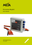
Short-circuit and ground fault indicator MEg61.4+
Short-circuit and ground fault indicator
MEg61.4+
1/ Introduction
The short-circuit and ground fault indicator MEg61.4+ (hereinafter MEg61.4+ indicator only) stems from well-proven functions of the previous ground fault indicators of
MEg61.4 series which were supplemented with new recording functions. Thus one unit
incorporates the ground fault indicator for MV levels where, except for identification of
faults and registration of fault states, continuous monitoring and long-term recording of
monitored quantities is performed as well.
The MEg61.4+ indicator identifies the segment of overhead line in which a ground fault
or a short-circuit (overcurrent) occurred. The MEg61.4+ indicator can be used for outdoor
installation on MV overhead line poles or for installation in internal environment with
cable MV lines. Bolted, arc and low impedance ground faults and all types of shortcircuits are indicated. It is primarily designed for use in compensated MV distribution
networks; however, it can be used in MV distribution networks with grounded neutral.
The MEg61.4+ indicator measures and records the data related to voltages, currents and
powers in the non-destructive electronic memory in preselected intervals.
Ground fault records consist of the curves containing 10 ms values and the curves containing individual samples of basic quantities.
The MEg61.4+ indicator has input circuits specially designed for connection of various
measuring converters and sensors. The voltage can be connected from the measuring
voltage transformer (MTN), from the capacitor or resistor dividers and from the
electric field sensor. The current can be connected from the measuring current transformer (MTP), from the split-core current transformer (PTD), from the AMOS sensor
(Rogowski coil) or from the magnetic field sensor.
The MEg61.4+ indicator is provided with a possibility of connecting two input signals
and one output signal. Types of ground connection and short-circuit faults are indicated
by indicating lights on the instrument panel and with a free contact on the indicator ter-
3
Měřící Energetické Aparáty
minals. It is possible to connect an external light signalling and external signalling reset.
It also includes the RS485 interface with MODBUS protocol.
A ground fault or a short circuit is signalled by interrupted light with the predefined
activation time, by relay contact closing or on request by means of the MODBUS protocol command.
2/ Technical parameters
Reference conditions
Usupply = 12 V DC, ambient temperature = 20 °C, relative humidity = 40 % to 70 %
f = 50.0 Hz, measured voltages and currents with identical frequency form a three-phase
system.
Basic parameters
Supply voltage:
12 V DC
Supply current:
80 mA, 12 V DC, 100 mA max.
Protection rating:
IP20
Operating temperature:
-25 °C to +60 °C
Relative humidity:
20 % to 90 % at 40 °C
Weight:
0.4 kg
Dimensions of the unit:
108 × 90 × 63 mm (length × width × height)
Installation:
DIN rail TC35 (35 × 7,5 mm)
Installation case (160 × 120 × 90 mm)
Terminal block, max. wire diameter: 2.5 mm
Communication/connector: USB/mini
RS485 (MODBUS), max. Baud rate:
115.2 kbit/s
Number or galvanically isolated outputs: 3 (SC, GF, Out1)
maximum switched voltage: 30 VAC, 30 V DC
maximum switched current: 30 mA
Number of inputs:
2 (dry contact)
Light activation time: 2 hrs (parametrizable)
4
Short-circuit and ground fault indicator MEg61.4+
Data memory:
4 MB + 4 MB (flash)
Data memory organization:
circulate memory
Recording interval:
from 1 sec to 15 minutes, set by software
Maximum number of recorded events:
1024
Maximum length of recorded event curve: 125 periods, 250 values URMS1/2
Fixed pre-trigger: 10 periods
Fixed post-trigger:
20 periods
Oscillogram:
64 samples/period
Oscillogram length:
selectable
standard: 8 periods
Storage temperature:
-25 °C to +80 °C
Protection rating:
IP20 – accessible parts, IP00 – inaccessible parts
Pollution degree:
2
Electromagnetic compatibility
ČSN EN 61326-1: 2006 Electrical equipment for measurement, control and laboratory
use – EMC requirements Part 1: General requirements 31st December 2006.
(ČSN EN 61000-4-2, ČSN EN 61000-4-3, ČSN EN 61000-4-4, ČSN EN
61000-4-5, ČSN EN 61000-4-6, ČSN EN 61000-4-9, ČSN EN 61000-4-11)
ČSN EN 55011 ed. 3:2010 Industrial, scientific and medical equipment – Radiofrequency disturbance characteristics – Limits and methods of measurement.
5
Měřící Energetické Aparáty
Voltage inputs
1. Transformer
Rated value Unom:
100 / √3 VAC
Maximum measured value:
120 VAC
Measuring accuracy:
better than 0.5 % Unom
Maximum value:
150 VAC
2. Resistor network
Rated value Unom:
100 / √3 VAC
Maximum measured value:
120 VAC
Measuring accuracy: better than 0.5 % Unom
Maximum value:
150 VAC
Input impedance:
> 1 MΩ
3. Resistor divider 22 kV
Rated value Unom:
2.4 VAC
Maximum measured value:
208 % Unom
Measuring accuracy: better than 0.5 % Unom
Maximum value:
260 % Unom
4. Resistor divider 35 kV
Rated value Unom:
2.4 VAC
Maximum measured value:
208 % Unom
Measuring accuracy:
better than 0.5 % Unom
Maximum value:
260 % Unom
5. Capacitor divider
Capacitor divider range:
8 pF – 150 pF
Number of internal amplification stages: 8
Rated level of MV network:
22 kV, 35 kV
6. Electric field sensor
Sensor location:
under the wire
Number of internal amplification stages: 8
Rated level of MV network:
6
22 kV, 35 kV
Short-circuit and ground fault indicator MEg61.4+
Current inputs
1. Transformer 1 A
Rated value Inom:
1 A AC
Measuring range, basic range:
2 % to 120 % Inom
Measuring range, high range:
120 % to 2000 % Inom
Measuring accuracy, basic range:
0.5 % Inom + 0.1 % of measured value
Measuring accuracy, high range:
10 % of measured value
2. Transformer 5 A
Rated value Inom:
5 A AC
Measuring range, basic range:
2 % to 120 % Inom
Measuring range, high range:
120 % to 2000 % Inom
Measuring accuracy, basic range:
0.5 % Inom + 0.1 % of measured value
Measuring accuracy, high range:
10 % of measured value
3. Input 20 mA
Rated value Inom:
20 mA AC
Measuring range, basic range:
2 % to 120 % Inom
Measuring range, high range:
120 % to 2000 % Inom
Measuring accuracy, basic range:
0.5 % Inom + 0.1 % of measured value
Measuring accuracy, high range:
10 % of measured value
4. Rogowski sensor
Rated value Inom:
250 A, 500 A
Measuring range, basic range:
2 % to 120 % Inom
Measuring range, high range:
120 % to 2000 % Inom
5. Magnetic field sensor
Sensor location:
under the wire
Number of internal amplification stages: 4
Current sensing range:
up to 300 A
Rated level of MV network:
22 kV, 35 kV
7
Měřící Energetické Aparáty
Active power
Rated value Pnom:
Unom ∙ Inom
Measuring range:
0.8 Unom ≤ U ≤ 1.3 Unom
0.02 Inom ≤ I ≤ 1.2 Inom
cos φ ≥ 0.5
Reactive power
Rated value Qnom:
Unom ∙ Inom
Measuring range:
0.8 Unom ≤ U ≤ 1.3 Unom
0.02 InomM ≤ I ≤ 1.2 InomM
cos φ ≤ 0.707
Active energy
Measuring range:
0.8 Unom ≤ U ≤ 1.3 Unom
0.02 InomM ≤ I ≤ 1.2 InomM
cos φ L ≥ 0.5
cos φ C ≥ 0.8
Voltage phenomena
Rated value:
Unom
URMS1/2 measurement range: 0.05 Unom ≤ U ≤ 1.3 Unom
T measuring range: 0.02 s < T ≤ 60 s
T measuring accuracy:
± 20 ms
Short-circuit currents IZ
Rated value InomZ:
20 ∙ Inom
IZ measuring range:
1.2 Inom to InomZ
IZ measurement accuracy:
10 % of measured value
Internal time
Accuracy:
1.0 sec / 24 hrs at ambient reference temperature
PLL (Phase Locked Loop) frequency range: 42.5 Hz to 57.5 Hz
Note: Measurement accuracies apply to the signal with fundamental frequency.
Overload capacity of current inputs: 2 Inom / 1 min, 10 Inom / 1.5 sec
8
Short-circuit and ground fault indicator MEg61.4+
3/Construction, wiring and description of the panel
The MEg61.4+ indicator is installed in a polycarbonate self-extinguishing case with the
dimensions of 108 × 90 × 63 mm designed for DIN rail mounting. The transparent panel
of the device can be sealed.
It is possible to deliver the MEg61.4+ indicator for installation also in the plastic
EURONORD case with overall dimensions 160 × 120 × 90, transparent plastic top cover
and cable grommets for connection of measured and other signals. The supply voltage
fuse is located in the cover case as well.
On the unit's panel, there is a green RUN LED light signalling the activity of the
MEg61.4+ indicator. The red LED signalling the occurrence of a short-circuit (SC),
yellow LED signalling the occurrence of ground fault (GF) and another yellow LED
signalling the state of output Out1 or the occurrence of unsuccessful reclosure (NOZ).
The USB mini connector designed for local communication is located on the unit's panel.
Lead connections for measured voltages, currents, power supply, communication lines
and others are carried out by screw terminals for wire cross-section up to 4 mm2. Measured voltages are brought to their relevant terminals U1 (34), U2 (32), U3 (30), common
terminals (33, 31, 29) or possibly to N (35,36).
Measured currents are brought to triplets of terminals I1 (1, 2, 3), I2 (4, 5, 6) and I3 (7, 8, 9)
whereas the input current terminal is marked with a dot. The black wires of the magnetic
field sensor are connected to terminals I1 (2), I2 (5) and I3 (8). For a different type of current sensor, the terminals I1 (2), I2 (5) and I3 (8) will remain unconnected and the input
current will make use of terminals I1 (1, 3), I2 (4, 6) and I3 (7, 9).
The supply voltage is connected to terminals +12V (17) and ⊥ (18).
Terminals IN (19, 21) are used for connection of the two-valued input signal against
the terminal ⊥ (20); terminals 19 and 21 are positive. The output signal SC (26, 27),
GF (24, 25), Out1 (22, 23) is implemented by a relay contact.
For remote communication, the RS485 interface at terminals 14, 15 and 16 is used.
The external light signalling is connected to terminal LI (10). The external light signalling
is fed from +12 V with the other pole.
9
Měřící Energetické Aparáty
Fig. 1: MEg61.4+ basic indicator unit dimensions
11,2
62,2
11,2
108
89,7
Fig. 2: MEg61.4+ indicator rating plate
36 35 34 33 32 31 30 29
27 26 25 24 23 22 21 20 19
SC
MEg 61.4
I3
1 2 3 4 5 6 7 8 9
10
In1
In2
www.e-mega.cz
LI
RS485
A G B
+12V
I2
Out1
RUN
FAULT INDICATOR
I1
GF
10 11 12 13 14 15 16 17 18
Short-circuit and ground fault indicator MEg61.4+
Tab.1: Description of MEg61.4+ indicator terminals
Terminal
number
Terminal
indication
1
2
Denotation
I1 current input (MTI, PTD, AMOS, white sensor wire)
I1
I1 current input (black sensor wire)
3
I1 current input (MTI, PTD, AMOS, red sensor wire)
4
I2 current input (MTI, PTD, AMOS, white sensor wire)
5
I2
I2 current input (black sensor wire)
6
I2 current input (MTI, PTD, AMOS, red sensor wire)
7
I3 current input (MTI, PTD, AMOS, white sensor wire)
8
I3
9
10
I3 current input (black sensor wire)
I3 current input (MTI, PTD, AMOS, red sensor wire)
LI
Output for external light signalling
11
12
Common grounding
13
14
A
1) 15
G
1) 16
B
1) 17
+12V
18
⊥
19
In2
20
⊥
21
In1
22
23
24
25
26
27
Out1
RS485 signal A
RS485 ground
RS485 signal B
Supply voltage +12 V
Supply voltage ground
Signal input 2
Ground for inputs, common with power supply ground
Signal input 1
Free relay contact out1
GF
Free relay contact for ground fault
SC
Free relay contact for short-circuit
11
Měřící Energetické Aparáty
Terminal
number
Terminal
indication
29
30
31
32
33
34
35
36
Denotation
U3 voltage input
U3
U3 voltage input, active signal
U2 voltage input
U2
U2 voltage input, active signal
U1 voltage input
U1
U1 voltage input, active signal
N
Common point for input voltages
RS485 interface is galvanically isolated
1)
Tab.2: Types of voltage and current inputs
Input
Voltage inputs
Current
inputs
Number code
Denotation
Comments
1
Transformer, Unom = 57,735 V
MTN
2
Resistor network, Unom = 57,735 V
MTN
3
Resistor divider, 22 kV
4
Resistor divider, 35 kV
5
Capacitor divider
6
Electric field sensor
1
Transformer, Inom = 1 A
MTP
2
Transformer, Inom = 5 A
MTP
3
Input 20 mA
PTD
4
Rogowski sensor
AMOSm
5
Magnetic field sensor
PTD: 100 A, 200 A, 300 A, 400 A, 500 A, 600 A
Rogowski sensor AMOSm: 250 A, 500 A
12
Short-circuit and ground fault indicator MEg61.4+
Fig. 3: MEg61.4+ indicator rating plate
IP00/IP20
MEg61.4+
Type I
Type U
POWER:12VDC+ 20%/80mADC 100mAmax
S.N.
Made in Czech Republic
Connection of input voltages and currents
The MEg61.4+ indicator is set by the manufacturer for connection of input voltages and
currents from the sensors indicated in Table 2. The type of input is marked with a number
code. This number code is indicated on the rating plate of the MEg61.4+ indicator and is
stored in the indicator's internal memory as well.
A shielded cable is used for connection of the input voltages from the resistor and capacitor dividers and from the electric field sensor.
Connection of input voltages
Fig. 4: Connection of input voltages from MTN – type 1
( 1 ) Transformátor 57,5V
MV L3
MV L2
35
34
33
32
31
30
29
N
T
U2
T
U3
T
36
U1
MV L1
MEg61.4+
13
Měřící Energetické Aparáty
Fig. 5: Connection of input voltages from MTN – type 2
( 2 ) Odporová síť 57,5V
MV L3
MV L2
35
34
33
32
31
30
29
N
T
U2
T
U3
T
36
U1
MV L1
MEg61.4+
Fig. 6: Connection of input voltages
from
resistor divider – type 3,4
(3)(4
) R dělič
MV L3
MV L2
35
34
33
32
31
30
29
N
T
U2
T
U3
T
36
U1
MV L1
MEg61.4+
14
Short-circuit and ground fault indicator MEg61.4+
Fig. 7: Connection of input voltages
from capacitor divider – type 5
( 5 ) C dělič
MV L3
MV L2
33
32
31
N
U2
T
30
U3
34
29
T
35
T
36
U1
MV L1
MEg61.4+
Fig. 8: Connection of input voltages
from electric field sensor – type 6
( 6 ) Snímač elektrického pole
MV L3
L3
MV L2
L2
MV L1
35
34
33
32
31
30
29
N
T
U2
T
U3
T
36
U1
L1
MEg61.4+
15
Měřící Energetické Aparáty
Connection of input currents
( 1 ) ( 2 )from
Transformátor
1A, 5A
Fig. 9: Connection of input currents
MTP – type
1, 2
7
L
L
6
I3*
8
9
L
5
I3
4
I2*
I2
3
K
I1*
2
K
1
K
I1
MEg61.4+
MV L1
MV L2
MV L3
( 3 ) PTDfrom PTD (20 mA) – type 3
Fig. 10: Connection of input currents
I3*
I3
7
8
9
L
6
K
I2*
5
L
I2
4
K
3
2
L
K
1
I1*
I1
MEg61.4+
MV Insulation
MV L1
MV L2
MV L3
PTD
PTD
PTD
16
Short-circuit and ground fault indicator MEg61.4+
( 4 ) Rogovského snímač
Fig. 11: Connection of input currents
from AMOSm (Rogowski coil) – type 4
I3*
I3
I2*
6
7
8
9
L
L
5
K
I2
4
L
I1*
3
2
K
1
K
I1
MEg61.4+
MV Insulation
MV L1
MV L2
MV L3
( 5 ) Snímač magnetického pole
Fig. 12: Connection of input currents from magnetic field sensor – type 5
MV L1
5
6
7
8
9
red
white
black
red
white
black
red
I3*
4
I3
I2
3
white
I2*
I1*
2
I1
1
black
MEg61.4+
MV Insulation
MV L2
MV L3
17
Short term:
Continuous:
Short term:
Continuous:
-40 … 120 °C
-40 … 80 °C
-40 … 250 °F
-40 … 175 °F
Europe EN 62208: 2003
Gost R
Měřící Energetické Aparáty
Accessories:
case
TMInstallation
1216
Mounting plate
TRM 0816
DIN-15 Mounting rail
+
The
can beraildelivered in the installation case with dimenMIV
10 basic MEg61.4 indicator
DIN-35unit
Mounting
TRH
1216
Mounting railcase houses the OPVA10-1 fuse holder with
sions
160 × 120 × 90 mm.DIN-35
The installation
TF1 A
28037
Wall fastening
lug case
(4 pcs)
fuse PVA10. In the lower
part of the
there are grommets for insertion of cables.
TH A
Grey plastic hinges (2 pcs)
The case is provided with a transparent cover to enable monitoring of the states of the
indicating elements.
In Figure 14, there is an example of wiring for voltage inputs from MTN and for current
inputs from PTD. In Figure 15, there is an example of wiring for voltage inputs from
capacitor dividers and for current inputs from PTD. Diagrams for individual voltage and
current input connections are used for other types of sensing elements.
Fig. 13:
Installation
case
dimensions
EURONORD
PC/ABS
160x120x90-140
160
121609
121
88
83
120
78
135.5
153
© Fibox Oy, Data subject to change without notice (printed: 27.10.2014)
18
Ø4
Ø4
90.5
76
113
136
90
30
Ø9.5
50
Ø5
Ø5
120
Ø9.5
148
5
Short-circuit and ground fault indicator MEg61.4+
29
U2
U3
T
27
26
25
24
23
22
21
20
19
B
30
+12V
31
A
32
T
33
T
34
T
35
T
36
U1
Fig. 14: Installation case wiring for input voltages from MTN and for input currents from PTD.
14
15
16
17
18
5
I3*
I3
7
8
9
10
11
12
13
FUS AKU T1A
T
+12V
RS485
T
U3
U2
U1
I1,I2,I3
L
6
L
4
I2*
I2
3
K
I1*
2
L
K
1
K
I1
MEg61.4+
29
U2
U3
T
27
26
25
24
22
21
20
19
+12V
30
B
31
A
32
T
33
T
34
T
23
14
15
16
17
18
I3*
8
9
10
11
12
13
RS485
7
FUS AKU T1A
L
I3
I2*
6
K
I2
5
L
I1*
4
K
3
I1,I2,I3
2
T
U1,U2,U3
K
1
L
I1
MEg61.4+
+12V
35
T
36
U1
Fig. 15: Installation case wiring for input voltages from capacitor dividers and for input
currents from PTD
19
Měřící Energetické Aparáty
4/Installation principles
Safety information. Maximum attention must be paid to this information.
Warnings draw attention to the facts, constituting safety risks to the operator.
Cautions indicate conditions and facts that may cause damage to the MEg61.4+
indicator.
Explanation of symbols used in User Manual:
Danger, electric shock risk
Note in documentation / Danger, risk of danger
Ground, grounding terminal
IP code
degree of protection provided by enclosure
The product is intended for recycling and collection spots.
Declaration of Conformity – European Community
20
Short-circuit and ground fault indicator MEg61.4+
Warning
• Be sure that the operator performing the installation must be equipped with
and use personal protective equipment and other safety devices
• Warning: The installation of sensing elements at MV level is governed by special regulations, operating instructions and safety instructions not included
in this manual.
• When using the MEg61.4+ indicator in a way not intended by the manufacturer, the protection provided by the MEg61.4+ indicator may be impaired.
• The MEg61.4+ indicator is a Class A product designed for industrial environments. It may cause radio interference in other environments.
• The operator installing and disassembling the MEg61.4+ indicator must have
qualifications for work near dangerous voltages. The operator must be trained in
giving first aid.
• The MEg61.4+ indicator may only be operated by qualified personnel equipped
with personal protection equipment against electrical injury.
• It is not allowed to connect the indicator to voltages higher than 150 VAC, otherwise there is a risk of electrical injury.
• The MEg61.4+ indicator may only be maintained and repaired by the manufacturer or service organizations trained by the manufacturer.
• It is not permitted to use other accessories than those included in the MEg61.4+
indicator delivery.
Caution
• The MEg61.4+ indicator can be installed on the DIN rail by means of the plastic
installation case with power supply fuse.
• The confusion of voltage and current types of MEg61.4+ indicator inputs and
sensing elements used may lead to indicator malfunction.
• Changing the type of voltage and current inputs can only be done by the manufacturer of MEg61.4+ indicator.
21
Měřící Energetické Aparáty
MEg61.4+ indicator installation
The MEg61.4+ indicator can be available for DIN rail installation or in plastic installation
case. It is expected that the signals of already installed relevant sensors will be used.
1. C
heck the type of inputs for voltages and currents whether they correspond to sensing elements used.
2. Connect the three-phase voltage and current inputs. Bring the current terminals
through additional short-circuiting terminal blocks. Use a shielded cable for voltage
connections; use a two-core cable for current connections.
3. C
onnect +12 V voltage with respect to correct polarity. For installation of the indicator in the installation case, connect the positive pole of the power supply to
the terminal of the built-in fuse. Connect the power supply cables with the power
supply switched off.
4. U
se the communication cable to connect the MEg61.4+ indicator with the master
communication unit by means of RS485 line.
5. C
onnect other cables to the relevant terminals if appropriate. These are outputs of
the relay contacts, input binary signals, resetting input and output to the external
indication light.
6. Check the light of the green RUN LED after power supply is switched on.
7. U
se the utility program to check if the output voltage and current are in phase. If
not, use the short-circuiting current clamps and interchange the beginning and the
end of the input current lines.
8. Use the utility program MERCI to set up necessary information for launching the
indicator.
22
Short-circuit and ground fault indicator MEg61.4+
5/Indication and control
If the indicator is active, the green RUN LED is lit steadily. In the state of FW upgrade,
the green LED flashes in a second interval.
For detecting the state of the indicator, its parametrization and reading out the current
records the USB interface is used in collaboration with MERCI software.
For connecting to the remote communication, use the galvanically isolated serial interface RS485 with integrated MODBUS protocol.
The contacts of the SC relay are closed when a short-circuit (overcurrent) occurs. At the
same time, the red SC LED starts flashing in a second interval. The LED is lit for a short
time.
The contacts of the GF relay are closed when a ground fault occurs in the downstream
direction of the indicator.
At the same time, the green GF LED starts flashing in a second interval. The LED is lit
for a short time.
When SC and GF faults occur, the LI output controlling the external intensive light is
released as well.
The states of indication can also be read out by means of the communication interface.
The states of indication can be cancelled after expiration of the set time (120 min as
a standard) by sending a command by MODBUS protocol via the RS485 bus or using
the user software.
If the indication is reset while the short-circuit is still present, the indication re-triggered
immediately.
The USB or RS485 interfaces operate simultaneously. If the indicator is interconnected
with the computer by means of the USB cable, the RS485 interface will not be blocked.
To prevent from conflicts with remote control, it is necessary to disconnect the RS485
interface when local communication is requested.
The state at the IN1, IN2 inputs can be transmitted remotely by the MODBUS protocol.
To evaluate the records use the DataViewer-DVMEg program.
23
Měřící Energetické Aparáty
6/Indicator components
The MEg61.4+ indicator incorporates these components:
– Basic unit
– Installation box with fuse and fuse holder
Sensing elements that can be connected to MV voltages and that provide the MEg61.4+
indicator with input voltage and current quantities are described in separate manuals.
7/Maintenance requirements
Besides protection against dripping water and usual cleaning of the unit and its panel, the
MEg61.4+ indicator does not require any other maintenance. The MEg61.4+ indicator has
no rotary or moving parts.
8/Method of delivery, handling and transport
The place of delivery of the MEg61.4+ indicator set if not specified otherwise, is the
manufacturer's place of business. The components of the MEg61.4+ indicator set are delivered in one box made of double-wall corrugated board. The boxes are recyclable. The
other accessory components are provided in packages corresponding to their weights and
mechanical dimensions.
Based on the specification in the purchase order, it is possible to send the MEg61.4+ indicator with accessories by the transport service chosen by the customer.
Due to the weight of the individual wrapped parts up to 15 kg, no special measures are
needed when handling the delivery.
Individual parts of the delivery are marked on their packages with the lists of components
inside.
24
Short-circuit and ground fault indicator MEg61.4+
9/ Ordering data
Basic:
• Quantity of short-circuit and ground fault indicators MEg61.4+
• Voltage level:
– 22 kV level
– 35 kV level
• Voltage input type
• Current input type:
– Transformer:
- 1 A
- 5 A
– PTD transformer with split core:
- 100 A
- 200 A
- 400 A
- 500 A
- 600 A
– Rogowski coil AMOS:
- 250 A
- 500 A
It is possible to deliver by special request:
• Plastic mounting case with grommets and circuit breaker.
The purchaser may place an order for training and calibration of the MEg61.4+ indicator
set with the manufacturer.
25
Měřící Energetické Aparáty
10/ Warranty
Two-year warranty is provided for the short circuit and ground fault indicator MEg61.4+
and its accessories from its sale. Defects incurred during this period due to a provably
defective construction, faulty workmanship or inappropriate materials will be repaired
free of charge by the manufacturer and the place of performance is the seat of the manufacturer of the MEg61.4+ indicator.
It is not permitted to open the MEg61.4+ indicator unit during warranty period.
The warranty becomes invalid if the user carries out unauthorized modifications or changes on the MEg61.4+ indicator or on its accessories if he connects the indicator incorrectly
or if the indicator was operated contrary to technical conditions.
The defects on the MEg61.4+ originating during the warranty period shall be claimed by
the user to the manufacturer of the indicator. Claims without the warranty certificate
enclosed will not be accepted.
The manufacturer bears in any case no responsibility for subsequent damages caused by
using the MEg61.4+ indicator. No responsibility which would exceed the price of the
MEg61.4+ indicator follows for the manufacturer from this warranty.
11/ Manufacturer
MEgA – Měřící Energetické Aparáty, a.s.
664 31 Česká 390, Czech Republic
Tel. +420 545 214 988
e-mail: [email protected]
web: www.e-mega.cz
26
Short-circuit and ground fault
indicator MEg61.4+
User manual
Měřící Energetické Aparáty, a.s.
664 31 Česká 390
Czech Republic
www.e-mega.cz
Edition: 11/2014