1
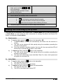
Comments: At rest the relay is not active, and +12 volts on the starter wire passes through the relay (through
87A & 30) normally. The starter disable output wire on the remote start module is activated when the LOCK
button is pressed on the remote control.
When a theft attempt happens, and the thief powers the ignition circuit (to hot-wire the vehicle), and the starter
disable was armed (by the LOCK button on the remote), the starter disable relay activates. The OEM start
wire is now open, (does not make connection) because 30 is no longer connected to 87A, and the vehicle is
unable to start.
Strengthening Current:
Example: Strengthening an output
Problem: A vehicle has a negative (-) trigger trunk release wire. The module has a negative trunk release
output wire. The remote start module is unable to supply the necessary current to activate the vehicle's trunk
release wire.
Solution: A relay is used to provide the necessary negative current to active the vehicle's trunk release wire.
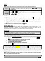
The Relay Connections
85: Connects to the start module's trunk release wire output. This becomes the negative trigger for the coil.
86: Connects to a fused +12 volt source.
87: Connects to a negative source (where the remote start module is grounded). This becomes the supply for
activating the vehicle's trunk release wire.
87A: No connection. This terminal is not used in this application.
30: Connects to the vehicle's trunk release wire.
Comments: At rest the relay is not active and the vehicle's trunk release switch is allowed to operate normally.
When the trunk release button is pressed, the start module's trunk release output activates the relay. The
ground signal is sent from 87 through 30 to the vehicle's trunk release wire activating the switch and opening
the trunk.
Clutch Bypass
In order to remote start a manual transmission vehicle, the clutch switch must be bypassed. Clutch safety
switch circuits can take many forms. Listed below are the most common ones. When testing to determine the
type of clutch circuit, it is recommended to use a computer safe logic probe. Some vehicles may also have a
separate or combined switch on the clutch pedal for cruise control. Usually a cruise control switch reacts the
moment you touch the pedal, where as a clutch switch reacts only when the pedal is near the floor. Once the
circuit type has been determined, you must recreate what happens electrically at the switch, with the remote
start module, to bypass the clutch during remote starts. Relays are often used to accomplish this. Always use
the Ground Out When Running (G.O.) as the negative trigger on your clutch bypass relays, as it is only active
during remote starts. NEVER permanently bypass a clutch switch. Do not attempt this if you are unfamiliar
with the use of relays, and diode isolation.
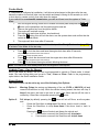
Before any Hot Wiring attempts:
Test and record the way each wire tests in the following positions:
With out the pedal pressed:
•
•
•
Test the wires with the Ignition OFF
Test the wires with the Ignition ON
Test the wires with the Key in the start position
With the pedal pressed:
•
Test the wires with the Ignition OFF
•
Test the wires with the Ignition ON
•
Test the wires with the Key in the start position
With this information for every wire at the switch, determining what type of clutch switching system you have will
be easy.
Direct Feed:
The simplest type of system to test and bypass is the “Direct Feed” system. This circuit simply interrupts the
+12v signal starter wire from the ignition switch to the starter solenoid. There are 2 wires in this circuit, the “key
side” wire which goes from the clutch pedal to the Ignition switch, and the “solenoid side” which goes from the
Installation Guide
P. 9