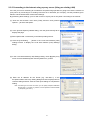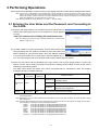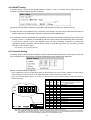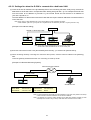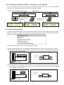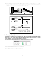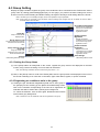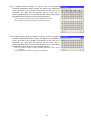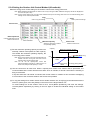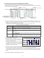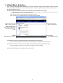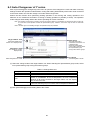
1
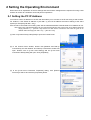
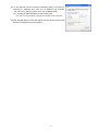
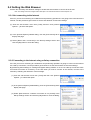
Mitsubishi Electric Building Air-conditioner Control System
Central Controller
G-50A/GB-50A
Operation Manual for Initial Setting Web
Contents
1 Introduction .........................................................................1
1-1 Conventions Used in This Manual........................................... 1
1-2 Computer Requirements ......................................................... 1
1-3 Notes on using G-50A with the integrated centralized control
software (TG-2000A)................................................................ 1
2 Setting the Operating Environment......................................2
2-1 Setting the PC IP Address....................................................... 2
2-2 Setting the Web Browser......................................................... 4
3 Performing Operations ........................................................6
3-1 Entering the User Name and the Password, and Connecting to
the G-50A ................................................................................. 6
4 Initial Settings......................................................................7
4-1 Setting the Current Date and Time.......................................... 7
4-2 Setting the Basic Information and External Input Functions ... 8
4-3 Group Setting ........................................................................ 13
4-4 Interlocked Setting................................................................. 15
4-5 Block Setting.......................................................................... 16
5 Functions 1........................................................................17
5-1 Error mail reports/E-mail communication .............................. 17
5-2 Energy-Save Control and Peak Cut Control ......................... 20
6 Functions 2........................................................................24
6-1 Limiting the Set Temperature Operating Range ................... 24
6-2 Night Mode Schedule ............................................................ 25
6-3 Auto-Changeover of Y series ................................................ 26
7 User Setting ......................................................................27
8 Registering a License for Optional Function ......................29
Before using the web browser to set the G-50A controller, please read this operation
Manual carefully to ensure correct operation.
Store this operation manual in a location that is easy to find.
1 Introduction
A special feature of Mitsubishi Electric Corporation’s “Central Controller G-50A” and "Central Controller
GB-50A" are that a PC connected to a LAN can be used to monitor the operation condition of air conditioners,
perform air conditioner operations, and make initial settings.
This document explains the procedures for making initial settings for the Central Controller G-50A using the
web browser.
Hereinafter, the central controller G-50A and GB-50A, unless otherwise specified, will be called "G-50A".
Note: As GB-50A is not equipped with a LCD for settings, the initial setting must be made on the Initial Setting Web or from the
Initial Setting Tool.
1-1 Conventions Used in This Manual
- Unless otherwise specified, "Windows" refers to Windows
®
Windows XP.
®
98, Windows
®
Me, Windows
®
2000 and
Note: Windows is a registered trademark or trademark of Microsoft Corporation USA in the United States and other countries.
- “Click” refers to the action of positioning the mouse cursor on the object (such as button or folder) and
pressing down and releasing the left mouse button once.
- Unless otherwise specified, the example screen images used in this manual are Windows XP and Internet
Explorer 6.0 screen images.
- The K transmission converter (PAC-SC25KAA) and OA processing unit (LOSSNAY) are not included in
systems shipped to North America (USA & Canada).
1-2 Computer Requirements
In order to monitor and operate air conditioners by web browser, your computer must meet the following
requirements.
Table 1-1 Computer Requirements
Item
Requirement
CPU
Pentium 133MHz or faster (300MHz or faster recommended)
Memory
64M Bytes or more (128M Bytes or more recommended)
Screen resolution
1024 x 768 or higher recommended
Microsoft® Internet Explorer 5.0 or later
Compatible browser
Note: You must have a Java execution environment
(Microsoft VM Ver5.0 or later or Sun Microsystems Java
Plug-in Ver.1.4.2 or later).
Note: You can check the Microsoft VM version by entering “jview” in a
command prompt.
Note: You can check the Sun Microsystems Java Plug-in version in
“Java Plug-in” in a control panel.
On-board LAN port or LAN card
One connector (10BASE-T)
Other
Pointing device such as a mouse
Note: Microsoft is a registered trademark or trademark of Microsoft Corporation USA in the United States and other countries.
1-3 Notes on using G-50A with the integrated centralized control
software (TG-2000A)
If the system is connected to the integrated centralized control software (referred to as TG-2000A hereafter),
make all settings and changes from the TG-2000A so that the data in TG-2000A and G-50A will match.
1
2 Setting the Operating Environment
Given below is an explanation of the PC settings and web browser settings that are required for using a web
browser to monitor air conditioner units and perform operations.
2-1 Setting the PC IP Address
You need to set an IP address on the PC that will enable you to connect to the G-50A using a web browser.
For instance, if the G-50A IP address is [192.168.1.1], the PC IP address will need to belong to the same
system (for example [192.168.1.101]).
If the G-50A is connected to an existing LAN, ask the LAN administrator to decide what PC IP address to use.
Note: When using a G-50A dedicated LAN, we recommend the G-50A main unit be given an IP address within the
range [192.168.1.1] — [192.168.1.40] and the PCs that will be connected to the G-50A be given an IP
address within the range [192.168.1.101] — [192.168.1.150]
(1) Click on [Control Panel] under [Start] to open the Control Panel.
(2) In the Control Panel window, double click [Network and Dial-up
Connections] and the Network and Dial-up Connections window will
open. Double click on [Local Area Setting] and the [Local Area
Connection Status] dialog will open. Click [Properties].
(3) In the [Local Area Connection Properties] dialog, click [Internet
Protocol] to select it and click the [Properties] button.
2
(4) In the [Internet Protocol (TCP/IP) Properties] dialog, click [Use the
following IP address] and enter the IP address (for example,
“192.168.1.101”) that you want to set in the IP address field.
You normally set [255.255.255.0] as the subnet mask.
Note: Ask your LAN administrator to provide the IP addresses and subnet mask.
(5) Click the [OK] button to close this dialog, and then close the other open
dialogs to complete the network setting.
3
2-2 Setting the Web Browser
Perform the necessary web browser settings to enable the web browser to connect to the G-50A.
Note: The settings and screen images used as examples in this manual are based on Internet Explorer 6.0.
2-2-1 Not connecting to the Internet
If the PC you use for monitoring air conditioners and performing operations is not going to be connected to the
Internet, use the procedure given below to set the web browser environment settings.
(1) Click the web browser menu item [Tools] and then click [Internet
Options…] to select that option.
(2) In the [Internet Options] tabbed dialog, click the [Connections] tab to
display that page.
(3) Select [Never dial a connection] in the Dial-up settings section and
click the [OK] button to close the dialog.
2-2-2 Connecting to the Internet using a dial-up connection
If the PC you use for monitoring air conditioners and performing operations is going to connect to the Internet
via a dial-up connection, use the procedure given below to set the web browser environment settings.
By performing these settings, a message will appear asking whether or not to use a dial-up connection when
an Internet connection is necessary. In the case when you want to connect to the Internet, connect to the
Internet by following the directions of this message.
(1) Click the web browser menu item [Tools] and then click [Internet
Options…] to select that option.
(2) In the [Internet Options] tabbed dialog, click the [Connections] tab to
display that page.
(3) Select [Dial whenever a network connection is not present] in the
Dial-up settings section and click the [OK] button to close the dialog.
4
2-2-3 Connecting to the Internet using a proxy server (Using an existing LAN)
If the PC you use for monitoring air conditioners and performing operations is going to access the Internet via
proxy server by connecting to an existing LAN such as a LAN within your company, use the procedure given
below to set the web browser environment settings.
By performing these settings, your PC will connect to a proxy server only when connecting to the Internet.
(1) Click the web browser menu item [Tools] and then click [Internet
Options…] to select that option.
(2) In the [Internet Options] tabbed dialog, click the [Connections] tab to
display that page.
(3) Select [Never dial a connection] in the Dial-up setting section.
(4) Click the [LAN Setting . . .] button in the Local Area Network (LAN)
settings section to display the Local Area Network (LAN) Settings
dialog.
(5) In the Local Area Network (LAN) Settings dialog, check [Bypass proxy
server for local addresses] and click the [Advanced...] button.
(6) Enter the IP address for the G-50A (e.g. 192.168.1.1) in the
Exceptions field of the Proxy Setting dialog and click the [OK] button to
close the dialog and then close the other open dialogs to complete the
setting.
Note: If connecting to more than one G-50A, you can specify multiple IP addresses
like [192.168.1.1; 192.168.1.2], however, it is also possible to use the asterisk
(*) and specify [192.168.1*].
5
3 Performing Operations
Given below is an explanation of how to connect to the G-50A and how to make various settings for the G-50A.
Note: If the G-50A is restarted due to circumstances like a power interruption, wait until the screen on the G-50A main unit
displays the normal operation screen (it takes several minutes before the normal operation screen is displayed) before
using a web browser to access the G-50A. If access is attempted while the G-50A is still starting up, the most recent data
might not be displayed or communication errors could occur.
Note: Default IP address of G-50A (GB-50A) is "192.168.1.1". (Factory setting)
3-1 Entering the User Name and the Password, and Connecting to
the G-50A
(1) Enter the web page address in the address field of the web browser as
follows and press the [Enter] key on the keyboard. A screen appears
for login.
http:// [IP address of the G-50A]/g-50/ administrator.html
Note: For example, type “http://192.168.1.1/g-50/administrator.html” if the G-50A IP
address is [192.168.1.1].
(2) To make it easier to connect the next time, click the web browser menu
item [Favorites] and click [Add to Favorites] to select that option and
add the address to your Favorites folder. Once this address is added
to your Favorites folder, it is not necessary to input the address of (1).
You can simply select it from your Favorites folder and the G-50A page will appear.
(3) Enter the user name and the password in the login screen, and click the [Login] button. A screen will
appear in which various setting are made. Procedures for making proper settings on each screen will be
explained in the following pages.
The table below shows the default user names and passwords for maintenance users and building
managers as well as available functions.
User
Maintenance
user
Building
manager
Default
user name
initial
Default
password
init
administrator
admin
Available functions
Initial settings
Date and Time, Basic System, Groups, Interlocked
LOSSNAY, Blocks
Functions 1
E-Mail, Peak cut
Functions 2
Set Temperature Range Limit, Night Mode
Schedule, Auto-changeover
Out of the functions listed above, the items to which access rights have been
given on the user settings screen are available.
Note: The user name and the password for building manager are the same as those of the building manager of the Web for
monitoring/operation.
Note: Maintenance users can make available to the administrator only the information necessary for normal operations (group
name setting etc.)
Note: The Web page is displayed in the same language as the computer uses and it is also possible to display the Web page in
other languages by entering the following Web page addresses.
English
German
French
Spanish
Italian
Russian
Chinese
Japanese
:HTTP://[The IP address for G-50A]/g-50/en/administrator.html
:HTTP://[The IP address for G-50A]/g-50/de/administrator.html
:HTTP://[The IP address for G-50A]/g-50/fr/administrator.html
:HTTP://[The IP address for G-50A]/g-50/es/administrator.html
:HTTP://[The IP address for G-50A]/g-50/it/administrator.html
:HTTP://[The IP address for G-50A]/g-50/ru/administrator.html
:HTTP://[The IP address for G-50A]/g-50/zh/administrator.html
:HTTP://[The IP address for G-50A]/g-50/ja/administrator.html
6
4 Initial Settings
4-1 Setting the Current Date and Time
Click [Initial Settings] in the menu, and [Date and Time] screen will appear on the screen. Enter the current
date and time, and then press the [Save Settings] button to send the current date and time to G-50A.
Note: If the user logs in as a building manager, the operations may be prohibited.
Note: If the system is connected to the TG-2000A, make all settings and changes from the TG-2000A so that the data in
TG-2000A and G-50A will match.
Current date/time
Enter the current date and
time here.
Summer time setting
Click to set the daylight saving
time.
Save settings
Refresh
Click to set the current date
and time.
Acquires the current Date and
Time from G-50A.
Item
Description
Save Settings
Enter the current date and time.
For the date, use the format [day - month - year].
Click the [Date/Time Set] button to set the current date and time.
Refresh
Acquires the current Date and Time from G-50A.
Current date/time
Click and tick the "Automatically adjust clock for daylight saving changes" box to
adjust the daylight saving time automatically, and select your own country.
Note: If your own country is not in the selection bar, select "Custom Settings". Click "Custom Settings"
button that will appear on the right to set the daylight saving time.
Daylight saving
date and time
Summer time setting
Set the daylight
saving time.
Custom Setting Screen
7
4-2 Setting the Basic Information and External Input Functions
Display the page needed to perform the G-50A basic setting by clicking [Initial Settings]-[Basic System] in the
setting menu pane. On this page, you perform the basic setting such as the G-50A unit name, network setting
and M-NET setting. Click [Save Settings] to send setting data to the G-50A. After the setting data are sent to
the G-50A, a message will appear asking whether or not to restart the G-50A. Click [OK] to restart the G-50A
to put the changes into effect.
Note: If the user logs in as a building manager, the operations may be prohibited.
External Input Setting
Unit Setting
Set the G-50A external input
setting.
Set the G-50A name and unit
ID.
Network Setting
M-NET Setting
Set the G-50A IP address and
subnet mask.
Set the G-50A M-NET
address, presence/absence of
K-Control units and range of
prohibited controllers.
Display Format
Used to set the display/ nondisplay of the filter sign on the
G-50A or on the Web.
Save Settings
Refresh
Send setting data to G-50A.
Read setting data from G-50A.
4-2-1 G-50A Unit Setting
In Unit Setting, set the G-50A name and unit ID.
(1) Enter the G-50A unit name in the [Name] field. You may enter a maximum of 40 alphanumeric or symbol
characters. The name set here is used on the display screen of the software that controls multiple G-50A
units and for the name of the sender in the body of error messages.
Note: The following characters cannot be used in the name: < > & " '
(2) Enter the G-50A unit ID in the [Unit ID] field. You must enter 6 numeric characters. Use this setting when
you want to control multiple G-50A units with unit IDs. The unit ID that is entered here will be used on the
display screen of the software that controls multiple G-50A units and for the sender ID in the body of error
messages.
(3) When [Refresh] is clicked, the G-50A production ID will appear in the [SERIAL No.] field and the G-50A
software version will appear in the [Software Version] field.
8
4-2-2 M-NET Setting
In M-NET Setting, set the G-50A M-NET address, whether or not a K-Control unit is present and which
machines send the prohibited controller command.
(1) Enter the G-50A M-NET address in the [M-NET Address] field. Normally you should enter [0].
(2) When K-Control air conditioners are connected, click [Used] in the [K-Control Units] field and enter the
M-NET address of K transmission converter in the [K Converter Address] field.
(3) If prohibited controller (prohibiting local operation) has been set, this setting determines the scope of this
setting s control, i.e. operation is prohibited for both the remote control and subordinate system controllers,
or just for the remote control. Click [SC/RC] when you want prohibited controllers to include both
subordinate system controllers and the remote control, or click [RC only] when you only want to prohibit
operation on the remote control.
Note: Normally, you should select [SC/RC].
4-2-3 Network Setting
In Network Setting, set the G-50A IP address, subnet mask and gateway address. If connecting to the G-50A
via a permanent LAN, consult with the network administrator before setting these addresses.
[Simple IP address setting of GB-50A]
The IP address that is set on the dip switch (SW2) on GB-50A main body has the priority. (Settings are shown below.)
When activating the value that is set on the initial setting Web, set all the switches on SW2 to OFF.
When the number of GB-50A units is 15 or less, it is recommend to set the IP address using the dip switch (SW2) on
GB-50A main body.
1
2
3
4
OFF OFF OFF OFF
SW 2
ON
OFF
1
2
3
4
SW1/2/3 EXT.I/O
POWER LAN LINK/ACT
1 2 3 4 5 6
M-NET
OFF
OFF
OFF
OFF
OFF
OFF
OFF
ON
ON
ON
ON
ON
ON
ON
ON
OFF
OFF
OFF
ON
ON
ON
ON
OFF
OFF
OFF
OFF
ON
ON
ON
ON
OFF
ON
ON
OFF
OFF
ON
ON
OFF
OFF
ON
ON
OFF
OFF
ON
ON
ON
OFF
ON
OFF
ON
OFF
ON
OFF
ON
OFF
ON
OFF
ON
OFF
ON
IP Address
IP address set by Initial Setting Web
Note: Default IP address "192.168.1.1".
(Factory setting)
192.168.1.1
192.168.1.2
192.168.1.3
192.168.1.4
192.168.1.5
192.168.1.6
192.168.1.7
192.168.1.8
192.168.1.9
192.168.1.10
192.168.1.11
192.168.1.12
192.168.1.13
192.168.1.14
192.168.1.15
Note: After changing the dip-switch settings, reset the power of GB-50A to activate the changes.
Note: If the IP address of GB-50A is forgotten, check the IP address that is registered on the monitoring PC (Web or TG-2000A) in
use. GB-50A can be started temporarily by using a specified IP address. It is recommended to paste a sticker with the IP
address on the unit, so that the IP address of GB-50A can be available at all times.
9
4-2-3-1 Settings for when the G-50A is connected to a dedicated LAN
(1) Enter the G-50A IP address in the [IP Address] field. If the LAN wiring has been newly set up, allocate IP
addresses to the G-50A units in a sequential order starting with [192.168.1.1]. For example the first G-50A
unit will receive an IP address of [192.168.1.1], the second G-50A unit will receive an IP address of
[192.168.1.2] and so on.
The Web Monitor PC that monitors and sets G-50A will also require network addresses consistent with the
rest of the LAN.
Note: When using a G-50A dedicated LAN, it is recommended to set the IP address as follows.
G-50A: Between [192.168.1.1] and [192.168.1.40] Web Monitor PC: Between [192.168.1.101] and [192.168.1.150]
[Example of IP address setting]
Hub
10BASE-T LAN straight cable
G-50A No. 1
192.168.1.1
G-50A No. 2
192.168.1.2
Web Monitor PC
192.168.1.101
G-50A No. 3
192.168.1.3
Note: Some hubs have a dedicated port for connection with another hub.
Connect the G-50A and Web Monitor PC to the normal ports.
(2) Enter the G-50A subnet mask in the [Subnet Mask] field. Normally, you should enter [255.255.255.0].
(3) When monitoring remotely or sending error mail via a dial-up router, enter the router IP address in the [Gateway]
field.
Leave the gateway address blank when not connecting via a dial-up router.
[Example of a Remote Monitoring System]
Telecommunication Network
Dial-up router
IP: 192.168.1.254
G-50A
IP Address
Subnet Mask
G/W Address
:192.168.1.1
:255.255.255.0
:192.168.1.254
Dial-up router, cellular phone etc.
Web Monitor PC
IP Address
Subnet Mask
G/W Address
Web Monitor PC
:192.168.1.101
:255.255.255.0
:Blank
Note: It is recommended to set the dial-up router IP address to [192.168.1.254]. Refer to the dial-up
router instruction manual for details of how to set the IP address.
Note: It is necessary to connect a modem (analog type or ISDN type) between the dial-up router
and telephone line when using a dial-up router that does not have a built-in modem.
10
4-2-3-2 Settings for when the G-50A is connected to an existing LAN
When connecting the G-50A to an existing LAN, consult with the network administrator who is responsible for
the LAN before setting the IP address, subnet mask, or gateway address.
[Example of a Permanent LAN System]
Backbone LAN
Gateway
IP: 10.130.1.250
Gateway
IP: 10.130.2.250
Receive from the LAN
administrator.
G-50A
IP Address
Subnet Mask
G/W Address
Receive from the LAN
administrator.
Web Monitor PC
Web Monitor PC
:10.130.1.1
:255.255.255.0
:10.130.1.250
IP Address
Subnet Mask
G/W Address
IP Address
Subnet Mask
G/W Address
:10.130.1.101
:255.255.255.0
:10.130.1.250
:10.130.2.51
:255.255.255.0
:10.130.2.250
4-2-4 External Input Setting
In the External Input Setting menu, set the G-50A external input function. By using external input functions, it is
possible to stop and run multiple air conditioners connected to the G-50A via the separately sold external I/O
adapter for G-50A (Model: PAC-YG10HA-E) using level signals and pulse signals.
(1) Select [Not in use] when not using the external input function.
(2) Selecting [Emergency stop (Level signal)] makes it possible to stop multiple units by using a level signal.
While this stop operation is being performed, operations such as running or stopping units are prohibited
on the G-50A unit or remote control.
1
2
3
4
5
6
7
8
9
Emergency stop/normal
Contact ON
Contact OFF
Emergency
Normal
DC 12V
Stop
Normal
Connection to G-50A (CN2)
(3) Selecting [ON/OFF (Level signal)] makes it possible to run or stop multiple units using a level signal. In this mode,
all air conditioner units connected to the G-50A will be run or stopped and run/stop operations will be prohibited
on the G-50A unit or remote control.
1
2
3
4
5
6
7
8
9
Run/Stop
DC12V
Contact ON
Contact OFF
Stop
Connection to G-50A (CN2)
11
Run
Stop
(4) Selecting [ON/OFF/Prohibit/Permit (Pulse signal)] makes it possible to use pulse signals to run multiple
units, stop multiple units, prohibit local operation and permit local operation. In this mode, it is possible to
freely operate the remote control except during the pulse signal input.
1
2
3
4
5
6
7
8
9
Run
Stop
Prohibit
Permit
DC12V
:Pulse generator
Connection to G-50A (CN2)
0.5 - 1.0 Seconds
Contact ON
Run
Contact OFF
Contact ON
Stop
Contact OFF
Run
Stop
0.5 - 1.0 Seconds
Contact ON
Prohibit
Stop
Contact OFF
Contact ON
Permit
Contact OFF
Permit
Prohibit
Permit
4-2-5 Setting the Display Format
Select display or non-display of “unit of temperature” and “filter sign” in the display format. When the filter sign
display is set to “OFF,” the filter sign on neither the LCD of the G-50A nor the monitor screen on the Web
browser will appear, even when the indoor unit detects a filter sign.
If the filter is regularly cleaned and the filter sign display is unnecessary, set it to [OFF].
(1) Select between [ºC] and [ºF] as the unit of temperature.
(2) Select [ON] to display the filter sign and [OFF] not to.
12
4-3 Group Setting
Display the page needed to register the group of air conditioners to be connected to the G-50A and to set the
group name by clicking [Initial Settings]-[Groups]. On this page, you perform the basic setting such as the
G-50A unit name, network setting and M-NET setting. Click [Set to G-50A] to send setting data to the G-50A.
Note: If the user logs in as a building manager, some of the operations may be prohibited.
Note: If the system is connected to the TG-2000A, make all settings and changes from the TG-2000A so that the data in
TG-2000A and G-50A will match.
Air Conditioner Registration
Register the air conditioning
units to be connected here.
Click to bring up the
registration screen.
Group No.
Group numbers will be
displayed here.
System Controller
Registration
Register the system
controllers to be connected
here. Click to bring up the
registration screen.
Group name for web
The group names to be used on
the Web screen are entered
here.
Remote Controller
Registration
Group name for LCD of
the G-50A
Register the remote
controllers to be connected
here. Click to bring up the
registration screen.
The group names to be
displayed on the LCD of the
G-50A are entered here.
Save Settings
Refresh
Send setting data to G-50A.
Read setting data from G-50A.
4-3-1 Setting the Group Name
(1) In the [Group Name for Web] field on the screen, register the group name to be displayed on the Web
screen, using a name consisting of no more than 20 characters.
Note: The following characters cannot be used in the group name: < > & " '
(2) Next, in the [Group name for LCD of the G-50A] field, enter the group name to be displayed on the LCD of
the G-50A consisting of no more than 10 numbers, upper case letters, hyphen, or space combined.
4-3-2 Registering air conditioner units in the group
(1) Clicking the [Air Conditioner Registration] field next to each group in
the [Groups] screen will bring up the [Select Unit Addresses] screen.
Click on the numbers corresponding to the units to be registered. All
selected units will be shown with a yellow-green background.
To cancel the selection, click on them again. Deselected items will be
shown with a gray background.
Note: A maximum of 16 air conditioner units can be registered in one group.
13
(2) To register remote controllers in a group, click on the [Remote
Controller Registration] field to display the [Select Unit Addresses]
screen, and click on the numbers corresponding to the units to be
registered. The ones that are selected will be shown with a
yellow-green background. To cancel the selection, click on them again.
Deselected items will be shown with a gray background.
Note: A maximum of 2 remote controls can be registered in one group.
Note: MA remote controls do not need to be registered to a group.
(3) To register system remote controllers in a group, click on the [System
Controller Registration] field to display the [Select Unit Addresses]
screen, and click on the numbers corresponding to the units to be
registered. The ones that are selected will be shown with a
yellow-green background. To cancel the selection, click on them again.
Deselected items will be shown with a gray background.
Note: The combined number of system controllers and remote controls cannot
exceed four.
Note: K-transmission converters do not need to be registered.
14
4-4 Interlocked Setting
To interlock the operation of LOSSNAY with the run/stop status of the indoor units, click on [Initial
Settings]-[Interlocked LOSSNAY] in the menu to bring up the Interlocked LOSSNAY screen, and enter the
interlock conditions. Click [Save Settings] to send setting data to the G-50A.
Note: If the user logs in as a building manager, the operations may be prohibited.
Note: If the system is connected to the TG-2000A, make all settings and changes from the TG-2000A so that the data in
TG-2000A and G-50A will match.
Interlocked Indoor Units
Registration
Interlocked LOSSNAY
Registration
Register the indoor units to
which LOSSNAY units are
interlocked here. Click to bring
up the registration screen.
Register the interlocked
ventilation equipment here.
Click to bring up the registration
screen.
Refresh
Save Settings
Read setting data from G-50A.
Send setting data to G-50A.
(1) Click in the Interlocked LOSSNAY registration field to display the
[Select Unit Addresses] screen, and click on the numbers
corresponding to the units to be registered. The ones that are selected
will be shown with a yellow-green background. To cancel the selection,
click on them again. Deselected items will be shown with a gray
background.
(2) Click on the Interlocked Indoor Unit Registration field to display the
[Select Unit Address] for the indoor units, and click on the numbers
corresponding to the units to be registered. The ones that are selected
will be shown with a yellow-green background. To cancel the selection,
click on them again. Deselected items will be shown with a gray
background.
Note: A maximum of 16 indoor units can be registered to operate with one
ventilator.
15
4-5 Block Setting
By performing block settings, multiples of air conditioner groups can be collectively monitored or operated from
the Web or TG-2000A. It also enables energy-save/peak cut controls. Bring up the Block Setting screen by
clicking [Initial Settings]-[Blocks] in the menu, and register the groups in the block to utilize these features.
Click [Save Settings] to send setting data to the G-50A.
Note: If the user logs in as a building manager, some of the operations may be prohibited.
Note: If the system is connected to the TG-2000A, make all settings and changes from the TG-2000A so that the data in
TG-2000A and G-50A will match.
Block Name
Group Registration
Register the block name to be
displayed on the Web screen
here.
Register the groups to be
included in the block here.
Refresh
Save Settings
Read setting data from G-50A.
Send setting data to G-50A.
4-5-1 Registering a block name
In the [Block Name] field on the screen, register the block name to be displayed on the Web screen, using a
name consisting of no more than 20 characters
Note: The following characters cannot be used in the group name: < > & “ ‘
4-5-2 Registering a group in a block
Click on the Group Registration field to display [Select Groups], and click
on the numbers corresponding to the groups to be registered. The ones
that are selected will be shown with a yellow-green background. (Putting a
cursor on the group number will display the group name.) To cancel the
selection, click on them again. Deselected items will be shown with a gray
background.
16
5 Functions 1
5-1 Error mail reports/E-mail communication
Click on [Functions 1] – [E-Mail] in the menu to open the [E-mail] window and make necessary settings to
perform remote monitoring via mail, using error mail report or the maintenance tool.
Click [Save Settings] to send setting data to the G-50A.
Note: The use of the error mail report function requires a separate license registration.
Confirm on the license registration screen (Ch8) that the license registration has been completed.
Note: If the user logs in as a building manager, the operations may be prohibited.
Mail Server Information
E-Mail settings of G-50A
Set the mail server/DNS server
information here.
The E-mail settings of G-50A
are set here.
Error Mail Settings
Mail Communication
Setting
Set the error mail destination
here.
Set the address of the mail
recipients here.
Refresh
Save Settings
Read setting data from G-50A.
Send setting data to G-50A.
5-1-1 Entering the E-Mail Information for the G-50A
Enter the E-mail information provided by either the ISP or the
LAN administrator.
Note: When sending E-mail via an ISP, a user contract with the ISP is
required.
Make necessary settings based on the functions that are to be used, using the table below as a reference.
Table 5-1 Items that Require Settings to Be Made (E-Mail Settings of G-50A)
Functions
Items
Mail Address
Error Mail Report
No SMTP
Uses SMTP
Authentication
Authentication
V
Mail Communication
No SMTP
Uses SMTP
Authentication
Authentication
V
V
V
User ID
V
V
V
Password
Interval of
mails
V
V
V
V
V
checking
incoming
17
5-1-2 Setting the Mail Server Information
Enter the mail server information provided by either the ISP or
the LAN administrator.
Either the IP address or the host name (server name) can be
entered in the mail server field.
Make necessary settings depending on the functions to be used, using the table below as a reference.
Table 5-2 Items that Require Settings to Be Made (Mail Server Information)
Functions
Items
Outgoing Mail Server (SMTP)
Error Mail Report
No SMTP
Uses SMTP
Authentication
Authentication
V
V
IP Address or
Host Name
Host Name
SMTP Authentication
DNS Server (Secondary)
IP Address or
Host Name
V
Incoming Mail Server (POP3)
DNS Server (Primary)
Mail Communication
No SMTP
Uses SMTP
Authentication
Authentication
V
V
(V)
*1
(V)
*1
V
V
Host Name
V
V
V
IP Address or
Host Name
IP Address or
Host Name
(V)
*1
V
(V)
*1
V
*1: Not necessary if the IP address is used as the mail server address.
5-1-3 Setting the Error Mail Destinations
(1) Enter the title of the error mail that will be sent from G-50A
in the [Mail Title] field. The title may contain a maximum of
40 characters.
Note: The following characters cannot be used in the mail title:
<>&“‘
(2) Choose the error type out of the following: [Unit Error], [Preliminary Unit Error], [Communication Error],
[General Equipment] and [User Setting 1] through [User Setting 6]. Then enter the mail address of the
recipient of the error mail.
(3) To send error messages only upon occurrences of certain
errors, click the User Setting button that appear when "User
Setting 1" through "User Setting 6" are selected, and
register the error codes to be reported in the user settings.
A maximum of 20 error codes can be set for each user
setting. In addition to specific error codes such as [1302] or
[6607], codes such as [10**] or [12**] can also be used. If
[10**] is set, for example, error mail will be sent upon an
occurrence of any type of errors between [1000] and [1099].
If error codes are set on this screen, confirm that the
address of the recipient is registered.
18
(4) To e-mail an error when an error occurs on general
equipment connected to PLC for general equipment,
click the PLC Connection button, which appears at
the time of selection of "General Equipment", to set
the IP address of PLC for general equipment.
The row number of the set IP address will be in an
error mail as a PLC number. (Eg. When an error
occurs on the No.20 PLC for general equipment that
is in the second row, "PLC2-20" will be displayed on
the error source
Note: TG-2000A is necessary to monitor the status of general equipment.
5-1-4 Setting the Addresses of the Recipient
To monitor and operate the unit with the maintenance tool via
mail from a remote location, enter the mail address of the
receiver in the [Mail Communication Setting].
A maximum of 10 addresses can be registered.
E-mail communication is possible only with the recipients
whose addresses are registered on this screen.
5-1-5 Mail format
Error mails are sent in the format shown below.
From:3-2F Area1(000001)
Date:11/09/2005 16:32:12
Error unit:PLC1-3
Error code:0091
Status:Occurrence
Item
Format
Mail title
Set title
From
G-50A unit name and unit ID
Date
dd/mm/yyyy hh:mm:ss
Error unit
Error code
Status
Remarks
Refer to 5-1-3 (1) for the setting of mail title.
Refer to 4-2-1 for the setting of G-50A unit name
and unit ID.
Date of error (Date, month, and year are
displayed in order.)
When an error occurs on air conditioners
- M-NET address of the error source
When an error occurs on general equipment
- PLC number (1 to 20) + connection number of PLC number indicates the row number on the
general equipment (1 to 32)
setting screen shown in 5-1-3 (4).
When a communication error occurs on PLC for
general equipment
- PLC number (1 to 20)
When an error occurs on air conditioners
Refer to the service manual for each unit.
When an error occurs on general equipment
0091:General equipment error
4-digit error
When a communication error occurs on PLC for
general equipment
0003:LAN communication error to PLC
0007:PLC stop
Error
status
"Occurrence" or "Recovery"
19
5-2 Energy-Save Control and Peak Cut Control
Click on [Functions 1] – [Peak Cut] in the menu to bring up the peak cut control screen, and make necessary
peak cut settings to use the energy-save or peak cut control function.
Click [Save Settings] to send setting data to the G-50A.
Note: The use of energy-save/peak cut control functions requires a separate license registration.
Confirm on the license registration screen (Ch8) that the license registration has been completed.
Note: If the user logs in as a building manager, some of the operations may be prohibited.
PLC Software for demand
input
Control Level
Set the range of electric power
(average electric power) at
each energy-save level.
Enter IP address and demand
level report recipient.
PLC Initialize
Click here to initialize the
internal memory of the PLC.
Temperature difference
between set point and inlet
With this limit or greater
difference, indoor units will not
be controlled on level 0.
Electric Amount Count
Software
Enter IP addresses, pulse units,
and watt-hour meter terminal
inf. here.
Indoor unit control method
Set the indoor unit control
method.
Outdoor unit control
method
Set the outdoor unit control
method.
Save Settings
Send setting data to G-50A
and PLC.
Refresh
Read setting data from G-50A
and PLC.
The use of energy-save/peak cut control requires the user to make certain settings as shown in the table
below. The settings required depend on the configuration of the system.
Table 5-3 Required Settings for Energy-save and Peak-cut Controls
Functions Energy-Save
Control
Items
5-2-1 PLC Initialize
Peak-cut Control
Electric Power
Monitor Method
Demand
Controller Method
V
V
V
5-2-2 PLC Software for demand input
5-2-3 Electric Amount Count Software
V
5-2-4 Control Level
5-2-5 Temperature difference between set
point and inlet
V
V
V
V
5-2-6 Outdoor unit control method
V
V
V
5-2-7 Indoor unit control method
V
V
V
Energy-Save Control
Electric Power Monitor Method
Always
performs level
0 control
Monitors electric
power
G-50A
G-50A
Demand Controller Method
Demand level
report
G-50A
Demand level
contact input
PLC (with Electric
Amount Count Software)
Demand
Controller
20
PLC (with Electric
Amount Count Software)
Pulse
Pulse-method
watt-hour meter
5-2-1 Initialization of the PLC (When the PLC is in use)
Before using the PLC Software for demand input or Electric Amount Count Software, click on the PLC initialize
button once to initialize the internal memory.
Note: Do not initialize the memory after the operation has begun, for it will clear all operation data.
5-2-2 Setting the PLC software for demand input (demand input method)
(1) Enter the IP address for the PLC software for demand
input.
(2) Enter the IP address of the G-50A to which the demand
levels are reported. A maximum of 10 addresses can be registered.
5-2-3 Setting the Electric Amount Count Software (Electric power monitor method)
(1) Enter the IP address of the electric amount count software.
(2) Enter the unit of the pulse that the watt-hour meter outputs.
Note: If the pulse unit field is left blank, there will be no change to the
pulse unit; only the information that was entered in the IP address
and DI board field will be saved.
(3) Select the terminal number of the DI board to which the watt-hour meter is connected. If it is connected to
terminal 2 on DI board 1, select 1-2.
Note: Select an input board from either 1 or 2, and select an input terminal from 0 to F. Choose the terminal to which the watt-hour
meter is connected that is used for peak cut.
5-2-4 Setting the Control Level (Electric Power Monitor Method)
Determine the range of electricity use for each control level (demand
level), taking into consideration such factors as delayed control of the
air conditioner. Enter the value that is 10 to 15% below the maximum
demand value (average electric energy value in 30 minutes) in the
blank next to Level 4. Decrease the value by about 10 % for each
level below. (The figure on the right shows the system with the
maximum electric energy at 200 kW.)
Note: The best set point depends on the system configuration of the electric equipment and the indoor environment in each
building. Choose appropriate set points accordingly.
Note: The amount of electricity that is actually used may exceed the demand value due to such unexpected incidents as controller
problems or broken transmission lines. Mitsubishi will not be responsible for such incidents.
5-2-5 Setting the temperature difference between set point and inlet (All methods)
When the energy-save level is set to 0 (It is always set to
level 0 in an energy-save control method), energy-save
control will not be performed for the indoor units that
show a greater difference between the set temperature and indoor temperature than the value set in the
window on the right.
Make the setting when some type of energy-saving control is effective at energy-save level 0 and the level of
comfort is high on priority list. (Choose between 3 to 9)
21
5-2-6 Setting the Outdoor Unit Control Method (All methods)
Make the energy-save control setting for the outdoor units for each energy-save level.
Note: M-NET addresses are displayed on outdoor units of City multi type. M-NET addresses and group names are displayed on
A-control units (Slim units).
Note: As for A-control outdoor units, only the inverter models can be put on the energy save control. Do not make the energy save
settings for the constant speed models.
Copy
Paste
Click to copy the settings.
Click to paste the settings.
Control Level
Batch Operations
Used to make settings for all
outdoor units at once.
Control Time
Maximum Capacity
Select the upper limit of outdoor
unit operating capacity.
(1) Set the maximum operating capacity at each level.
Normally, outdoor units operate at 100% capacity.
The smaller the maximum operating capacity, the
more energy will be saved.
Note: Energy-saving effects cannot be expected when the
outdoor units are running with low load and are
operating below the set capacity level.
Note:
Do not use the capacity-save control with
heat-accumulating units (ICE-Y) or Multi S units. On
these units, always set the capacity to “100%.”
Capacity
Select the control time.
Maximum Capacity at 80%
Amount of saved energy
80%
Capacity
Value
No energy-saving With energy-saving effects
effects
Time
(2) Set the control time at each level. When a capacity-save control over outdoor units is performed, it is
recommended that the control time be set to either 30 or 15 minutes, for shorter control time is not likely to
bring much benefit.
If any time other than “30-minute” is selected, the control is done on rotation so as to avoid the overlapping
of control time of the connected outdoor units as much as possible.
(3) To copy the settings for a certain outdoor unit to another outdoor unit, click [Copy] so the selected items are
shown in yellow-green, and click [Paste] on the screen for the target outdoor unit.
To make settings for all the outdoor units at once, check [Batch Operations], and enter the settings.
Uncheck [Batch Operations] by clicking on the box again to enable the individual setting of the outdoor
units.
22
5-2-7 Setting the Indoor Unit Control Method (All methods)
Make the energy-save control settings for the outdoor units for each energy-save level.
The settings are made for each operation block. If the operation blocks have not been set up, refer to section
4-5 on how to set the operation blocks.
Copy
Paste
Click to copy the settings.
Click to paste the settings.
Control Level
Batch Operations
Used to make settings for all
outdoor units at once.
Control Method
Control Time
Select indoor unit control
method.
Select the control time.
(1) Set the control method for each level. Fan control can be performed without letting the users know that the
energy-save control is performed because it performs thermo-off control of the indoor units and the mode
display on the remote controller LCD will not change.
The modes on the K-control models and the models before free plan will change to “Fan.”
Table 5-4 Indoor Unit Control Method
Control Method
Type of Control
N/A
No control is performed.
Cooling/dry : +2ºC; Heating : -2ºC (No control during fan/auto)
±2ºC Control
Fan Control
Note: Shifts to a ±2ºC control at control begin time, and goes back to the normal setting at control end
time.
Performs “capacity save 0% control (thermo OFF)” on free-plan indoor units and A-control slim
indoor units, and performs fan operation control on the K-control units and the units before
free-plan units.
Note: Switches to thermo OFF or Fan mode at control begin time, and switches back to the original state
at control end time.
Stops the indoor units
Stop Control
Note: Sends [Stop] at control begin time, and goes back to the original run/stop status at control end time.
Note: If set to [30 minutes][Stop], the groups that are being controlled cannot be operated from any
controller.
(2) Set the control time for each level.
The unit of control is 3 minutes. If “6 minutes” is
selected, 3 minutes of control is performed twice
during each 30 minute period
If any time other than “30-minute” is selected,
the control is done on rotation so as to avoid the
overlapping of control time of the connected
outdoor units as much as possible.
Control was performed for 6 min.
0
3 5
8 10 13 15
Control time of day
18 20 23 25 28 30min.
Group 1
Group 2
Group 3
(3) To copy the settings for a certain operation block to another operation block, click [Copy] so the selected
items are shown in yellow-green, and click [Paste] on the screen for the target operation block.
To make settings for all the operation blocks at once, check [Batch Operations], and enter the settings.
Uncheck [Batch Operations] by clicking on the box again to enable the individual setting of operation
blocks.
(4) Click [Save Settings] to send setting data to the G-50A.
23
6 Functions 2
6-1 Limiting the Set Temperature Operating Range
Click on [Function2]-[Set Temperature Range Limit] in the menu to open the set temperature range limit
screen, and make necessary settings to limit the set temperature operating range of the local remote
controller.
Each user operation will be limited by setting the lower limit and the upper limit of the set temperature for
cooling operation, which leads to energy saving.
Note: The set temperature operating range can be limited only on ME remote controller (PAR-F27MEA-E or PAR-F27MEA-F) and
on Simple ME controller (PAC-SE51CRA-F). (The lower limit for cooling mode and the upper limit for heating mode can be
set on PAR-F27MEA-E, and the upper limit and the lower limit for cooling, heating and automatic mode can be set on
PAR-F27MEA-F or PAC-SE51CRA-F.)
Note: The set temperature range for all modes can be limited on the browser operation screen (for administrator), G-50A
operation screen, and TG-2000A operation screen regardless of any settings being made. (The setting made on personal
browser operation screen is in effect on the personal screen.)
Note: If the user logs in as a building manager, some of the operations may be prohibited.
Batch operation
Click to set all groups
collectively.
Group No., group name
Copy
Group numbers and group
names will be displayed.
Click to copy the settings.
Paste
Click to paste the settings.
Set temperature range
display
The set temperature range is
displayed.
Refresh
Save settings
Read setting data from G-50A.
Send setting data to G-50A.
Lower limit
Upper limit
(1) Click the set temperature range display to display the
setting screen. Set the temperature range for cooling,
heating and automatic mode.
Click [OK] to return the previous screen.
Note: When displayed in Fahrenheit, the temperature is
displayed in 2°F steps.
(2) Click [Save Settings] to send setting data to G-50A.
Note: When copying settings of a group to another group, click [Copy] button. The screen will change to a selection screen
(yellow-green). Click [Paste] on a group to be copied.
Note: When setting all groups collectively, click [Batch operation] button, and input settings.
24
6-2 Night Mode Schedule
Click on [Function2]-[Night Mode Schedule] in the menu to open the night mode schedule screen and make
necessary settings to switch the outdoor unit operation mode to the night mode (low-noise operation), and set
the night mode time interval.
Use this mode when low-noise operation of the outdoor unit is preferable during night.
Note: Make this setting only when all the units operate normally. When connection error occurs at the indoor or the outdoor unit,
night mode target units may not be displayed normally.
Note: The noise level to be reduced varies depending on the unit model.
Note: If the user logs in as a building manager, the operations may be prohibited.
Night mode start time
Night mode end time
Click to set the start time.
Click to set the end time
Target outdoor units
Click to select the outdoor unit,
which performs night mode
control.
Refresh
Save settings
Read setting data from G-50A.
Send setting data to G-50A.
(1) Set the time interval in [Night mode start time] and [Night mode end time].
Note: When the starting time and the ending time is the same, night mode operation will always be performed.
(2) Select the outdoor unit, which performs night mode operation from [Target outdoor units].
Note: M-NET address numbers for each outdoor unit are displayed in the target unit field.
(3) Click [Save Settings] to send setting data to the G-50A.
25
6-3 Auto-Changeover of Y series
Click on [Function2]-[Auto-changeover] in the menu to open the auto-changeover screen and make necessary
settings to switch the operation mode between cooling and heating automatically of the indoor units connected
to the same outdoor unit. Set the change over mode and the target units.
Please use this function when performing heating operation in the morning and cooling operation in the
afternoon on air conditioners that either of cooling or heating operation is possible (Y series). The operation
mode changes automatically without the need of operating all remote controllers.
Note: The operation mode (cooling or heating) is set by the majority decision in consideration of performance value of each unit,
or on the basis of the operation mode of the representative group. Therefore, some rooms may be hotter or colder than
others.
Note: If the user logs in as a building manager, the operations may be prohibited.
Target outdoor units
Member group
The M-NET address of the
outdoor unit is displayed here.
The group name that is
connected to the outdoor unit
is displayed here.
When the representative
group mode is selected, select
the representative group
among these member groups.
Changeover mode
The changeover mode is
displayed here.
Refresh
Save settings
Read setting data from G-50A.
Send setting data to G-50A.
(1) Select the change mode of the target outdoor unit. When selecting the representative group mode, select
one representative group among the member groups.
Table 6-1 Change Mode List
Change mode
Content
None
Select this when the function is not used.
The operation mode (cooling or heating) is set and changed by the majority
decision in consideration of the set temperature, the room temperature
difference of all groups connected to the target outdoor unit, and capacity
value of each indoor unit.
Changes the set temperature of the representative group, and the operation
mode of the member group in accordance with the temperature difference.
Auto
Representative Group
(2) Click [Save Settings] to send setting data to the G-50A.
26
7 User Setting
Click on [User settings] in the menu to open the user setting screen and make necessary user settings to limit
available functions of a building manager and to change user names and passwords of maintenance user and
building manager.
A building manager must change group names when a tenant has been changed. However, for basic setting
information, such as connection information of air conditioners, that one doesn’t want to be changed, please
make this user setting. Moreover, when building manager forgets his user name or password, the user logs in
as a maintenance user can be set again.
Maintenance user name,
password
User name and password can
be changed.
User name and password for
building manager
User name and password can
be changed.
Available functions
The building manager selects
the available functions
Refresh
Save settings
Read setting data from G-50A.
Send setting data to G-50A.
(1) When changing the user names or passwords of maintenance users, type new information in [User name],
[New Password] and [Retype Password] fields to change user names or passwords of maintenance users.
Note: If the user logs in as a building manager, the user name and the password of the maintenance user are not displayed, and
cannot be changed.
(2) When changing the user names or passwords of building managers, type new information in [User name],
[New password] and [Retype Password] fields to change user names or passwords of a building manager.
(3) To set the available functions of a building manager, click functions that should be available. The ones that
are selected will be shown with a yellow-green background.
To cancel the selection, click on them again. Deselected items will be shown with a gray background.
For more information of each function and available functions, refer to the next page.
Note: If the user logs in as a building manager, the present status can be checked, but cannot be changed.
27
Table 7-1 Available Function List
Function
Content
Date and time
Basic system
Current date and time setting
*1
G-50A network setting, external output setting
Group name
Groups
Group structure
Initial setting
*1
*1
Interlocked LOSSNAY
Blocks
E-Mail
Block name
Block structure
Block name setting
*1
*1
Functions1
Peak cut
Control method
System structure
Functions2
Group name setting
Connection setting of indoor units, remote controllers
and system controllers in a group
Connection setting of interlocked LOSSNAY
*1
Registration setting of groups in a block
Address to report an error mail, Setting of mail
communication partner
Setting
of
average
electric
range,
temperature difference between set point an
inlet, and control method of indoor units and
outdoor units
PLC initialize, PLC settings
Set temperature range limit
Temperature operating range limitation setting
Night mode schedule
Night mode time interval setting
Auto-changeover
Auto-changeover of cooling and heating
*1: At factory shipment, the operation of the building manager is prohibited.
(4) Click [Save Settings] to send setting data to the G-50A.
28
8 Registering a License for Optional Function
Given below is an explanation on how to register a license for optional functions. In the Login screen (see3-1),
click [License registration for optional functions] and the License Registration of Optional Functions screen will
appear.
Please ask the dealer you purchased the product from for more details on the optional functions and how to
purchase a license number.
Sub menu
Click to return the Login page.
Optional functions
selection box
Current status
Select the optional function
you want to register.
This indicates whether the
optional function is available for
use.
License number entry
field
Enter the license number
required for registration.
Software version
Software version is displayed.
Register the license
button
Click to register the license.
License registration of optional functions
(1) Open the Registration of Optional Function screen.
Enter the Web page address in the web browser address field,
and click the [Enter] (Return) key on the keyboard to display the
Login screen (See 3-1). Click on this screen’s menu item
[Registration of Optional Functions] to open the Registration of
Optional Functions screen.
(2) Register an optional function.
First select the optional function you wish to register from the
selection box in the Selecting Optional Function selection. When
an optional function is selected, the current section will indicate
whether it is available for use.
Next enter the license number you purchased for the optional
function in the license number entry field and click the [Register
the license] button. Once this is done, the optional function will be
available for use.
If you were unsuccessful in registering an optional function, check that you did not enter the wrong license
number by mistake, that the correct optional function was selected from the selection box, and that the
G-50A main units date and time are set correctly.
29
HEAD OFFICE: MITSUBISHI DENKI BLDG., 2-2-3, MARUNOUCHI, CHIYODA-KU, TOKYO 100-8310, JAPAN
WT04526X04