Transcript
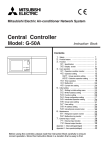
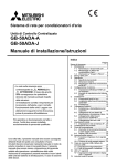
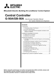
WT03777X02
4
External size
of remote
controller
ON/OFF remote controller
1 The space as shown in the diagram at right is required whether the controller is installed on the wall or in
the electric box.
2 Procure the following parts locally.
• Electric box for two units
• Thin-copper wiring pipe
• Locknut and bushing
PAC-YT40ANRA
Installation Manual
When using the electric box
• When fitting to the electric box, seal the join between
the electric box and the wiring conduit with putty.
Controlled group
PAC-YT40ANRA
ERROR CODE
ON
OFF
GROUP SETTING
30
30
ADMINI STERED
GROUP
CENTRALIZED
ON/OFF
Room name sheet
1
2
3
Wall
Wiring
pipe
4
Meeting room 5 Meeting room 6 Meeting room 7 Meeting room 8
5
6
7
8
4 – 1 (To register) Press the Individual ON/OFF switch of the group in which you want to make an entry.
NOTE: A protection sheet is stuck to the room name sheet.
Remove the protection sheet before using the room name sheet.
Remote controller
cord
To register:
Press Individual ON/
OFF switch of
desired group
Seal with putty.
Electric box
This symbol denotes what could lead to a personal injury or damage to your property if you misuse the PAC-YT40ANRA.
Ensure that installation work is done correctly following this installation
manual.
Any deficiency caused by installation may result in an electric shock or fire.
Install in a place which is strong enough to withstand the weight of the
PAC-YT40ANRA.
Any lack of strength may cause the PAC-YT40ANRA to fall down, resulting in
personal injury.
All electrical work must be performed by a licensed technician, according
to local regulations and the instructions given in this manual.
Any lack of electric circuit or any deficiency caused by installation may result in
an electric shock or fire.
Firmly connect the wiring using the specified cables. Carefully check
that the cables do not exert any force on the terminals.
Improper wiring connections may produce heat and possibly a fire.
Do not move and re-install the PAC-YT40ANRA yourself.
Any deficiency caused by installation may result in an electric shock or fire.
Ask your distributor or special vendor for moving and installation.
Never modify or repair the PAC-YT40ANRA by yourself.
Any deficiency caused by your modification or repair may result in an electric
shock or fire.
Consult with your dealer about repairs.
Seal with putty.
Bushing
To remove the remote controller cover, gently rotate a
slotted screwdriver in the claw points as shown in the
right diagram.
Seal with putty.
4 – 2 (To remove) Press twice, the Individual ON/OFF switch of the group in which you want to remove an entry.
Remote
controller cords
To remove entry:
Press Individual
ON/OFF switch of
desired group
Do not install in any place exposed to flammable gas leakage.
Flammable gases accumulated around the body of PAC-YT40ANRA may cause
an explosion.
Do not use in any special environment.
Using in any place exposed to oil (including machine oil), steam and sulfuric
gas may deteriorate the performance significantly or give damage to the component parts.
Wire so that it does not receive any tension.
Tension may cause wire breakage, heating or fire.
When installing the electric box
Electric box
for two units
Do not install in any place at a temperature of more than 40°C or less than
0°C or exposed to direct sunlight.
Do not install in any steamy place such as a bathroom or kitchen.
Avoid any place where moisture is condensed into dew. Doing so may cause an
electric shock or a malfunction.
Do not install in any place where acidic or alkaline solution or special
spray are often used.
Doing so may cause an electric shock or malfunction.
Connects to CN1 of
the remote controller
main unit
Refer to 8
Use standard wires in compliance with the current capacity.
A failure to this may result in an electric leakage, heating or fire.
CAUTION
Do not press any control switch using a sharp object.
Doing so may cause an electric shock or a malfunction.
Over-tightening the screws may result in deformation or cracking of the lower case.
TB7
TB3
[113]
[210]
group 13
[051]
TB7
TB3
[001]
[002]
[112]
[111]
group 12
[003]
[010]
group 11
[004]
1
Rotary switch setting
01-50
CAUTION
×1
[201]
Central controller
Model: G-50A
[102]
[103]
[104]
[105]
[106]
group 1
group 2
group 3
group 4
group 5
group 6
Power supply unit
Model: PAC-SC50KUA
Central management transmission line
Indoor and outdoor transmission line
Interlocked operation with ventilation unit
M-NET model address setup (address duplication not possible)
Address setup
Indoor unit / Interlocked Any address within the range specified at
right.
unit
The smallest address of indoor unit in the
Outdoor unit
same refrigerant system + 50
The smallest address of indoor unit in the
Remote controller
same group +100
Any address within the range specified at
ON/OFF remote
right.
controller
Address
1-50
51-100
101-200
201-250
The only indoor unit this device can be used to operate is an M-NET control indoor unit. It will not operate a K control indoor unit, even with a K
transmission converter (PAC-SC25KAA).
● To connect the system controller on the transmission line for central control and
connect a power supply unit for transmission lines (PAC-SC50KUA), leave the power
supply switch connector (CN41) on the outdoor unit as it is.
♦ Up to 2/6/12 system controllers can be connected when a power supply unit (PACSC50KUA) is connected.
System remote controller (SR)
Central controller
ON/OFF remote
Schedule timer (ST)
(G-50A)
controller (AN)
Group remote controller (GR)
1~2 unit(s) (Note 1)
1~6 unit(s)
1~12 unit(s)
Power consumption of G-50A and AN are as follows:
· One G-50A unit = Three AN units
One AN consumes 1/3 as much power as one G-50A.
· One AN unit = Two GR units
One GR, SR, or ST consumes half as much power as an one AN.
(Note 1) Up to 2 central controllers (G-50A) can be connected only when different
systems are kept separate.
CAUTION4: Using with a certain combination of multiple system controllers.
● To connect the system controller on the transmission line for central control and be
powered from the outdoor unit (Applicable only to R410A compatible models), disconnect the male connector from the female CN41 power supply switch connector,
and connect it to the female CN40 power supply switch connector on only one of the
outdoor units.
Up to three system controllers (AN/SR/ST/GR) can be connected on the transmission line for central control of the M-NET without the need for a power supply unit for
transmission lines.
When the system controller is connected on the transmission line for central control and is powered from the outdoor unit, the number of indoor units that are
connectable to each refrigerant system is reduced by 3/1/0.5 unit(s) for each system controller that is connected
G-50A
Converted into three
indoor units
AN
Converted into one
indoor unit
group 7
CAUTION
1. This diagram shows the configuration of transmission line, and omits power
supply line for clarity.
2. Establish one shield ground for M transmission line within the system.
3. Unit remote controllers cannot be used.
4. The number of system controllers which may be supplied with power are
found by multiplying the given number by the appropriate capacity coefficient in the following table (decimal fractions are rounded up).
Central controller
(G-50A)
3
(e.g) In the case of a system with 1 central controller, 2 ON/OFF remote controllers, and 2 group remote controllers.
These controllers are connectable because the calculation result is 6.
1 × 3 + 2 × 1 + 2 × 0.5 = 6
1
Group
Total number (<= 6 [AN])
Number of connected group remote controller × the coefficient
Number of connected ON/OFF remote controller × the coefficient
Number of connected central controller × the
coefficient
5
Group
Slave system
controller
Group
Group
Master system
controller 2
Group
Group
(2) Level signal and pulse signal
(A) Level signal
Collective ON/OFF switch
CENTRALIZED
2
3
Group setting
ON
OFF
Controlled group
OFF
Contact ON
Contact OFF
Emergency
STOP
Normal
Normal
6
7
“HO” is displayed and Centralized Control lamp flashes.
• If groups setting information has already been registered, “H1” is displayed after the
power is supplied, then the screen will be blank and normal operation becomes possible.
(This state is described below as normal mode.)
Group setting
Controlled group
No. 1
No. 2
Green
Yellow
Level signal for Emergency stop/
Normal
Emergency stop/Normal input
Not used
No. 3
Orange
Not used
Not used
No. 4
Red
Not used
Not used
No. 5
Brown
Remote controller
main unit
Pulse signal for ON/OFF,
Prohibit/Permit
On input
Off input
Prohibit local remote controller
operation input
Permit local remote controller
operation input
Level signal for ON/OFF
ON/OFF input
Not used
green
yellow
orange
red
brown
ON/OFF
or
Emergency stop
Maximum
10m
Remote controller
main unit
ON
OFF
Prohibit
Permit
Maximum
10m
1 The no voltage contact point and the extension cable are not supplied with the product.
2 The length of the connection cable extension should not exceed 10m. (Use a cable of 0.3 mm2 or thicker.)
3 Cut off the cable not being used close the connector and properly insulate the cut off ends with tape or the like.
2.
External signal output function
(1) External output
In the case when one or more air conditioner units are “ON”, and an error is occurring on one or more air conditioner units, a signal indicating that
an error is occurring is output.
(2) External output specification
CN3 Lead wires (4 wires, with black tube)
No. 1
Yellow
No. 2
Orange
No. 3
Red
No. 4
Brown
1 “On” is output even when there is “Error”.
(3) Example of a recommended circuit
In the case of a relay being operated
50
Detail of each terminal
yellow
orange
Diode
(*2)
red
• The group No. that can be controlled by this remote controller will become the range from the group No. set here until that group No. + 15.
(Example) When the remote controller’s own address is 210, and the minimum controlled group No. is modified from “10” to “25”
In this case, the controlled group No. range has been changed so that group 25 through group 40 can be controlled;
Individual ON/OFF switch 1 = Group 25, Individual ON/OFF switch 2 = Group 26, and so on to Individual ON/OFF
switch 16 = Group 40.
• Switch to the initial screen for group setting of 1 by switching SW3-2 to “OFF”.
The first, hook the two upper claws and then fit it as shown in the above diagram.
When the external input and output functions are used and the lower case cable entry points are being used, mount the remote controller main unit while
pushing the external input/output cables to the electric box side.
(Push towards the electric box sides from the lower case until the cable sheath part is reached.)
OFF
(B) Pulse signal cases
brown
Change the direction of modification by setting ON/OFF on SW3-4.
(The displayed direction will alternate between / on the screen.)
• SW3-4 = OFF: ( lit): Pressing the Collective ON/OFF switch will change the
value in the + direction.
• SW3-4 = ON: ( lit): Pressing the Collective ON/OFF switch will change the
value in the - direction.
To remove the remote controller main unit, insert a minus screwdriver into one of the open
slots and move it in the direction of the arrow
as shown in the diagram at right.
ON
Common 0V
green
Note: Only change this setting when you want to change the group range controlled by this remote controller.
The group range controlled by this remote controller is determined by this remote controller’s address setting. If trouble arises from the
controlled group range that was determined by this remote controller’s address, perform the minimum controlled group No. setting regardless of whether this remote controller is set to master setting or slave setting.
(Example) If you want to control exactly the same groups with two ON/OFF remote controllers, it is not possible to duplicate the remote
controller address. Therefore the range of the groups that the two ON/OFF remote controllers can control will not match. In such
a case, the minimum controlled group No. setting can be modified to determine a controlled group range that is not relative to the
remote controller’s own address setting.
[Minimum controlled group No. setting screen]
• The minimum group No. (two digits) controlled by this remote controller will flash
Group setting
ON
on the screen. This group No. is the group No. of Individual ON/OFF switch 1.
OFF
The screen will also display the position mark ( ), which will flash on the conControlled group
trolled group part of the screen.
1 2 3 4
• The group No. (two digits) display is changed by pushing the Collective ON/
OFF switch. Match the display with the group No. you want to set for the IndiGroup setting
ON/OFF
vidual ON/OFF switch 1.
⇔ · · · · · · · · · · · · · · · ·⇔
OFF
*The same applies to Prohibit/Permit.
Lead wires (5 wires)
2 (Minimum controlled group No. setting) Set SW3-2 to “ON”.
02
Signal 2
Contact ON
OFF Contact OFF
CN2
[Initial screen for group setting]
• The address display part “- - -” and the position mark ( ) on the group setting
part of the screen flash.
• If the group setting information has already been registered in the initial screen
for group setting, the registered unit No. of the smallest address will be displayed.
⇔
Signal 1
(A) Level signal cases
1 In the case where the Emergency stop/Normal signal is selected, when the external input signal contact OFF changes to contact ON,
“Normal” changes to “Emergency stop”. When contact ON changes to contact OFF, “Emergency stop” changes to “Normal”.
2 In the case where the ON/OFF signal is selected, when the external input signal contact OFF changes to contact ON, “OFF” changes to
“ON”, and when contact ON changes to contact OFF, “ON” changes to “OFF”.
(B) Pulse signal cases
1 If the “ON” signal is sent while the equipment is on, the equipment remains on. (The same applies to OFF, Prohibit and Permit.)
2 In the case where local remote controller operation is prohibited, the ON/OFF operations by the local remote controller are prohibited.
3 Set the pulse duration (contact ON period) to 0.5sec or longer.
(4) Example of a recommended circuit
[Screen displaying remote controller’s own address]
• The remote controller’s own address flashes for about 2 seconds and then the
screen display switches to the initial screen for group setting.
01
0.5s or longer
Contact ON
ON Contact OFF
4
8
7
0.5s or longer
(A) Level signal cases
1 2 3 4
9. Mount the remote controller main unit.
CAUTION
ON
OFF
ON/OFF
Remote controller main unit
Press the cover until it snaps shut. If not, it may fall off.
(B) Pulse signal
(Example) Case of ON/OFF signal
Contact ON
Contact OFF
1 Set SW3-1 to “ON”.
Connect this to
connector CN1
Remote controller lower case
External signal input function
(1) External Input
By using an external no voltage contact signal, it is possible to send Emergency stop/Normal, ON/OFF or Prohibit/Permit local remote controller
operation commands to all units being controlled. (This is selected by the SW4 setting. SW4 is mounted on the main unit board.)
SW4
Comment
No.
External input signal functions
No.2 No.3
Do not use external input signal (This is the
OFF
OFF
1
––––––––––––––––––
factory setting.)
The Emergency stop state prohibits the ON/OFF operation from the
2 Send a level signal for Emergency stop/Normal
OFF
ON local remote controller and the ON/OFF operation and the change
Prohibit/Permit operation from this unit.
This state prohibits the ON/OFF operation from both the remote
3 Send a level signal for ON/OFF
ON
OFF
controller and this unit.
Send a pulse signal for ON/OFF and Prohibit/
ON
ON When the contact is ON, make the pulse duration 0.5sec or longer.
4
Permit
• It is possible to switch to initial setting mode on when “HO” of (2) is displayed on the screen or when all groups are off in normal mode. When the
ON/OFF lamp of an individual group is lit during normal mode, press the Collective ON/OFF switch to turn off all groups.
Remote controller main unit
Controlled group
CAUTION
1.
3. Operation to switch to initial setting mode
• Connect firmly as shown in the diagram at right. The system will not operate unless these connections are made.
• After connecting the wiring, ensure that the upper case does not hang off
the cord as shown in the diagram below at the right. This may result in a
break in the cord, and thus cause problems with operation.
• Always pass the cord through the hook to hold it in place.
Hook
5. The ON/OFF Remote Controller can manage up to 50 air-conditioning or
ventilation units.
6. One ON/OFF remote controller can control a maximum of 16 groups. The
numbering range of the groups that can be managed can be modified
using the initial settings but normally the group numbers starting from last
two digits of the remote controller’s own address up until a value 15 higher
than that can be managed.
(Example) Case where ON/OFF remote controller’s own address is set to
210 Group number: Groups 10 - 25 can be controlled.
In the case where a problem exists with the controlled group range determined by the remote controller’s address setting; By performing the minimum controlled group No. setting in the initial settings described later in the
manual, regardless of whether this remote controller has a master setting or
subordinate setting, it is possible to set a controlled group range that has no
relationship with the setting value of the remote controller’s own address.
For details, refer to 5 Initial Setting .
7. As current consumption is twice that with remote controller when this equipment is connected to the indoor and outdoor transmission wiring, assume
two remote controllers for each of these units when calculating connections.
Group
Master system
controller 2
(3) External input specification
Addresses between 201 and 250 may be set
with the system remote controller. The place of
100 is fixed to “2”.
external
input mode
switch
Using the External Input and Output
Individual ON/OFF switch
When using the external input and output function, also connect the external input cable
connector (5 wire) to CN2 and connect the external output cable connector (4 wire) to
CN3.
CAUTION
ERROR CODE
ON
OFF
ADMINI STERED
GROUP
Controlled group
slave/
master
Controlled group
PAC-YT40ANRA
8. Connect the lower case connector to connector CN1 on the remote controller main unit.
Capacity coefficient
Group remote controller (GR)
ON/OFF remote
System remote controller (SR)
controller (AN)
Schedule timer (ST)
1
0.5
Master system
controller 1
201-250
Group setting
Remote Controller cord
• Cut off the shaded area from the upper cover using a knife, nippers, etc.
• Take out the remote control cord connected to the terminal block via this portion.
External input/output cables (Only in the case when using external input and output functions directly connected to the wall)
• Using a suitable knife or cutting implement, cut and remove the thin walled part on the
left and right side of the remote controller main unit.
CN2 side: For external input cable
CN3 side: For external output cable
• Insert the external input/output cables through these points.
[157]
[107]
6
SW3
GROUP SETTING
• Set the dip switch 3-1 to “OFF” to exit from group setting mode.
• “H1” will be displayed and the startup process will be performed.
• The startup process has completed once “H1” is no longer displayed.
The operation state becomes normal mode and normal operation is possible.
Group setting
1 2 3 4
Centralized Control
7. Wiring hole for fitting directly on the wall
[101]
ON
OFF
1. Remove the cover.
2. Supply power to this remote controller.
• The switch is set to “Master” when shipped from the factory.
SW4-1: OFF = “master”
ON = “slave”
SW4-2, SW4-3 are for switching between external input modes.
[008]
6 Set SW3-1 to “OFF”.
5
6. When used in conjunction with the master system controller (centralized controller), set the system remote controller to “Slave” with
the switch as shown in the diagram below.
[007]
• First register all the indoor units, stand-alone LOSSNAY units or general purpose interface, then register the local remote controller, and lastly
register the slave system controller. By following this sequence for the setting operation, the registering operation can be performed smoothly.
• You cannot register units of a different type (indoor units, ventilation units) in the one group.
• A single group can have a maximum of 16 units (indoor units or ventilation units) and the combined total of local remote controllers and system
controllers in the group can be as many as 4 units.
• When connecting local remote controllers to the system, you must register the local remote controller address in the group.
However, if the local remote controller is an MA remote controller, registration in the group is not required.
When using the external input and output functions, use the external input and output cables provided with the remote controller. (A 5 wire cable for input
and 4 wire cable for output are provided.)
Slave system
controller
Group
All Individual ON/OFF
lamps
5 Repeat operations 3 and 4 to perform the registration operations for all controllers.
A slave system controller which exceeds the management range of
the master system controller of two or more.
5-1 Initial Setting Method
Address
[009]
group 10
[006]
Group
When using a system where
PAC-YT40ANRA is controller by
a different system controller.
PAC-YT40ANRA is set as the
slave system controller. In this
case, the group settings are not
performed with PAC-YT40ANRA.
• The address No. that can be set on the remote controller is within
the range of 201-250.
The 100 digit is fixed at “2”.
• If an address other than those listed above is set, an address setting error occurs and “AdE” is displayed.
• The rotary switch is set to 01 when shipped from the factory.
ON/OFF remote
controller
Controlled group
A common group is managed by
more than two master controllers.
3
Rotary switch
[110]
[005]
Master system
controller
Group
Ventilation unit
[011]
Unit
Master system
controller 1
Remote controller wiring entry points can support electrical
wiring of maximum 1.25 mm2.
However 0.75 mm2 electrical wiring is recommended for use.
[012]
When using a system consisting
only of PAC-YT40ANRA.
PAC-YT40ANRA is set as the
master system controller. In this
case, the group settings are
performed with PAC-YT40ANRA.
Do not use crimp terminals to connect to remote controller terminal blocks. It connects to the circuit board and will cause trouble.
Remote controller main unit
[013]
Unit group which are not under the
management of the master controller
and are managed by the slave system
controller.
Unit
No polarity
Remote controller cord
procured locally.
5. Set the system remote controller address with the rotary
switches.
Indoor unit
Management
range of PACYT40ANRA
• The display will change to as shown on the left and when the removal process is
successfully performed, the initial screen for group setting of 1 will be displayed.
This process also resets the minimum controlled group No. setting to the controlled group range determined by the remote controller’s own address.
Group setting
+
Individual ON/OFF
switch 16
NOTE: It is not possible to set the master and slave settings with more than one group
remote controller and control the same groups. Also, the groups listed below
cannot be set.
Management range of the
master system controller
Unit
A.1 B.2
Example: Address of 201
[014]
Management range
of PAC-YT40ANRA
Install wiring correctly in accordance with the diagram at right.
CAUTION
Individual ON/OFF
lamp when address is
removed from group
Individual ON/OFF
switch 1
(*1) Master system controllers and slave system controller
(Terminal block)
M-NET remote
controller
Initial Setting
There are the following two types of initial setting mode.
(A) Minimum controlled group No. setting
The remote controller determines the controlled group range using its own address setting. If the controlled group range that is determined by the
remote controller’s own address causes trouble, change the controlled group range by performing the minimum group No. setting.
(B) Group setting
This is used to include the controllers controlled by the remote controller in each group. Indoor units, ventilation units, local remote controllers and
slave system controllers are entered in each group.
• When setting a master system controller
It is necessary to perform the group setting. Moreover, it is necessary to perform minimum controlled group No. setting when required.
• When setting a slave system controller
It is necessary to perform minimum controlled group No. setting when required. The group setting is not necessary. The group setting is performed
on the master system controller side.
• When interlocking control of a ventilation unit with an indoor unit, the interlocking setting is necessary but it is not set on the remote controller.
Perform the interlocking setting on the local remote controller when this remote controller is set as the master system controller or perform it on the
system controller of the master system controller setting when this remote controller is set as the slave system controller.
(If a ON/OFF remote controller is set as the system controller in the master system controller setting, set the interlocking setting on the local remote
controller.)
4. Connect the remote controller cord to the terminal block on the lower case.
× 10
[015]
Connects to CN1
of the remote
controller main unit
Refer to 8
NOTE: - Choose a flat plane for installation.
- Fasten the electric box at more than two places when installing directly on the wall.
When installing the remote controller in a hospital or communication facility, take ample countermeasures against noise.
Inverters, emergency power supply generators, high-frequency medical equipment, and wireless communication equipment can cause the remote controller
to malfunction or to fail. Radiation from the remote controller may effect communication equipment and prevent medical operations on the human body or interfere with image transmission and cause noise.
NOTE: The remote control cord is not supplied with the product.
Prepare electrical wiring that conforms to the specifications given below.
Electrical wiring specification (CVVS)
Use 1.25 mm2 cable for any extension that exceeds 10m.
• 10m or shorter: 0.75 mm2 two-wire cable
• Longer than 10m: 1.25 mm2 two-wire cable
[059]
Wood screw
External
output cable
entry point
External
input cable
entry point
Do not remove the insulation sheet.
Doing so may cause an electric shock.
Confirming the Supplied Parts
System Configuration
5
Seal the cord lead-in hole with putty or
silicon rubber. (See 2 above)
Do not touch the PCB (Printed Circuit Board) with your hands or with
tools. Also do not get dirt on the PCB.
It may cause a fire or mulfunction.
Controlled group
4 – 3 (To remove all entry data) Press Individual ON/OFF switch 1 and Individual ON/OFF switch 16 simultaneously for
3 seconds.
Remote controller cord
(See 4 below)
Push open the knock-outs
covering the entry points
for the external input and
output cables on the lower
case and thread the
external input and output
cables as described on the
left.
• Beginning from the state where the address No. is lit, press the Individual ON/
OFF switch of the group you want to remove the displayed entry from twice in
succession.
The controller entry of the displayed address No. will be removed.
• When this removal process is performed successfully, the address No. will be
flashing and the lamp of the group from which the entry was removed will change
from lit to not lit.
Group setting
(Press twice)
When rotating the driver, gently rotate without applying
much force. If too much force is applied, it could break
the claw parts.
When installing directly on the wall
External output cable (4 wire)
Connects to CN3
External input cable (5 wire)
Connects to CN2
Confirm that the box includes the following parts, in addition to this installation manual:
1. Remote controller (cover, body, Remote controller lower case) ................................... 1
2. Cable for external input (5 wire) ................................................................................... 1
3. Cable for external output (4 wire) ................................................................................. 1
4. Cross recessed pan head screw (M4 × 30) ................................................................. 2
5. Wood screw (4.1 × 16, used for directly hooking to the wall) ....................................... 2
6. Room name sheet ....................................................................................................... 8 (Includes 4 spare sheets)
7. Operation Manual ........................................................................................................ 1
Press the cover until it snaps shut. If not, it may fall off.
CAUTION
In the case where external
input and output functions
are used
Remote controller cord
(See 4 below)
Cross recessed
pan head screws
To dispose of this product, consult your dealer.
Never contact the power supply with the control wiring terminals.
Doing so will certainly cause the controller to catch fire.
Do not wash with water.
Doing so may cause an electric shock or a malfunction.
CAUTION
3. Install the lower case on the electric box or directly on the wall.
Do not touch any control switch with wet hands.
Doing so may cause an electric shock or a malfunction.
Completely seal the wire lead-in port with putty etc.
Any dew, moisture, insects entering the unit may cause an electric shock or a
malfunction.
Cord Taken Through Top of Remote Controller
Cord Taken Through Rear of
Remote Controller
CAUTION
♦
Controlled group
Individual ON/OFF lamp
when address is
registered in the group
WARNING
NOTE:
• Beginning from the state where the address No. is flashing, press the
Individual ON/OFF switch of the group you want to register the address No. in.
The controller of the displayed address No. will be registered to that group.
• When this address No. is successfully registered, the address No. and lamp of
the registered group will change to lit and the address No. will be included in this
group.
• If there is no controller for the specified address No., or if you are trying to register different types of units to the same group, an error will occur. In such a case
the address No. and the Individual ON/OFF lamp will flash.
Group setting
The initial setting is set while the cover is removed. Fasten the cover after performing the initial setting.
This symbol denotes what could lead to serious injury or death if you misuse the PAC-YT40ANRA.
Ask your dealer or technical representative to install the unit.
Any deficiency caused by your own installation may result in an electric shock
or fire.
3
Controlled group
1 2 3 4
Lock nut
● After reading this manual, keep in a handy place. When removing or repairning the unit, give this manual to the installer. When the user changes, also
give to the new user.
2
• Switch the direction of modification by setting ON/OFF on SW3-4.
(The displayed direction will alternate between / on the screen.)
SW3-4 = OFF: ( lit): Pressing the Collective ON/OFF switch will change the
displayed address in the + direction.
SW3-4 = ON: ( lit): Pressing the Collective ON/OFF switch will change the
displayed address in the - direction.
• In the case when the displayed address No. is already registered, the address
No. and the registered group’s Individual ON/OFF lamp will be lit.
Group setting
ON
OFF
11. Fasten the remote controller cover.
● Read these Safety Precautions and perform installation work accordingly.
● The following two symbols are used for dangers that may be caused by incorrect use and their degree of severity:
• Press the Collective ON/OFF switch to change the address No. display so that
it matches the address No. you want to register.
- - - ⇒ 000 ⇔ 001 ⇔ 002 ⇔ · · · · · · · · · · · · · · ⇔ 250
Group setting
ON/OFF
When fitting directly on the wall
• When cutting a hole in the wall for the remote controller cord (ie when the remote controller cord exits from the rear of the remote controller), seal this hole in the same way.
• When fitting directly to the wall as in 3, seal the cut-out in the upper case with putty.
Safety Precautions
WARNING
CAUTION
Write the room names with a pencil or print the room names using a commercial sticker printer and stick them on.
2. Seal the remote controller cord lead-in with putty in order to prevent the possible entry of
dew, water droplets, other insects.
The content of this instruction manual is limited to the installation of an ON/OFF remote controller (hereafter remote controller) that is capable of
managing and controlling a maximum of 50 units comprised of air conditioners, LOSSNAY units and general purpose interface (the units can be spread
over a maximum of 16 groups). For information on how to wire and install the air conditioning units, refer to this manual for them.
To ensure a safe environment is maintained, read the following 1 Safety Precautions and perform installation work accordingly.
3 (Group Setting) Display the Address numbers you want to include.
10. Write the room names on the room name sheet and insert it into the remote controller main unit as described below.
Extra space around
remote controller
30
1. Choose a location in which to install the system remote controller (electric box) in accordance with the following requirements:
CITY MULTI Control System
and Mitsubishi Mr. SLIM Air Conditioners
1
How To Install
120
GB
brown
Remote controller
main unit
Maximum
ON/OFF
Error/Normal
For relay Z1, Z2 use the specifications given below.
Operation coil
Rated voltage: DC12V, DC24V
Power consumption: 0.9 W or less
(*1) Provide a power supply suitable to the relay used.
(DC 12V or DC24V)
(*2) Always insert diodes at both terminals of the relay coil.
Power supply (*1)
L1: ON/OFF display lamp
L2: Error display lamp
10m
1 When units are “ON” and an error is occurring, each element is ON.
2 The extension length of the connection cable can be up to 10 m.
3 The relay, lamps, diodes and extension cables are not supplied with the product.
Do not turn the screwdriver in the slot. Doing so may
damage the slot.
NOTE: A protective sheet has been affixed to the control panel.
Remove it before starting.
SR, ST, GR
Converted into 0.5 indoor unit
2
4
6
8