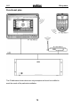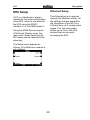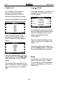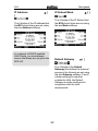
1
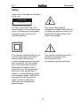
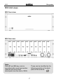
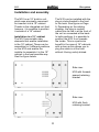
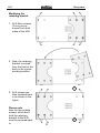
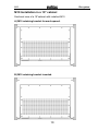
as82
of
of
Re:system
M10
Modular Audio Multiroom
System
Dominating Entertainment.
Revox of Switzerland.
Re:system
M10
1
M10
Re:system
M10 – Introduction
3
Safety
4-6
M10 Unit Views
7
Installation and Assembly
M10 in a 19” Cabinet
8
10
Overview: M10 Connection Panel
Connection Panel Description
Ethernet Interface
11
12-15
16-19
M10 Setup
Ethernet Setup
Source Setup
Remote Setup
Version Control
20
20-24
25
25-29
30
Guarantee
Scope of delivery
Disposing of your old device
31
31
31
Technical Data
32
2
Re:system
M10
M10
Working quietly in the background, the modular M10 Audio
Multiroom System in 19” format,
can be relied on to supply a
complete house with music. With
the plug-in Multiroom module, up
to 32 rooms can be included.
This allows you to choose in the
individual rooms between a highquality stereo sound or an
exciting Home Cinema experience.
Once new technologies establish
themselves on the market, Revox
can offer the corresponding
module. As a Revox customer,
you just have to buy the new
module for your existing M10 and
can start to enjoy the new
technology immediately. No new
operating
concept
remote
controls or conversions needed.
In this way, we protect your
resources and offer your option to
integrated and use new media
simply and uncomplicatedly.
The Multiroom system is operated
either through a M208 remote
control or a wall-mounted panel,
which in many cases is available
in a design to match existing
switch programs. The GIRA and
Feller (CH) companies offer
particularly attractive solutions.
The M10 offers a USB both on
the front and back of the unit to
help the installer make the basic
settings safely and quickly. There
is also the option for remote
maintenance and/ or Multiroom
control with the a LAN, using the
integrated network socket.
Which music sources can be
heard in the individual rooms
depends only on which modules
are in use. The M10 offers 9 free
plug-in slots that can be
populated with modules. These
modules cover a whole range of
options from an analogue record
deck right up to a future-safe
network connection to the
Worldwide Web. The modular
approach, which Revox has
followed for decades was also an
essential
element
in
the
development of the M10.
3
Re:system
M10
Safety
Take note of the label on the back
of the unit.
CAUTION
R I S K OF E L E C T R IC S HO C K
D O NO T O P E N
In order to avoid the risk of an
electric shock, do not remove any
covers. Maintenance and repairs
should only be carried out by
qualified experts.
This symbol warns about
“dangerous voltage” within the unit.
Touching live parts can lead to an
electric shock, depending on the
level of the voltage.
This symbol indicates that the unit
is only connected to the mains
power socket through two
contacts (phase and neutral) and
has no ground. For this reason,
the unit is particularly well isolated and must pass a strict
insulation test. This guarantees
that even if the neutral line is
broken, no accessible part of the
unit is under voltage. The M10 is
equipped with this protection
class in order to effectively
eliminate sound-damaging
ground-loops.
This symbol indicates important
advice for operation and
maintenance in the
accompanying documentation.
4
Re:system
M10
Installation and operation
Safety measures
Please check the unit and
accessories for any signs of
transit damage after unpacking.
Read the operation manual
through carefully before starting
to use the unit. Keep the manual
for later reference.
Unusual operation
Unplug the unit from the mains
immediately in the event of any
unusual noises or odours. Have
the unit checked by your dealer
without delay.
A unit that shows signs of
mechanical damage or which has
had liquid in it may not be
connected to the mains supply.
Do not open the unit
The unit may not be opened as
there is a risk of electrification.
Use the supplied mains cable.
The unit’s power supply and
connections values (mains
voltage, frequency) must be
checked before connecting it to
the mains. Fuses used in the
device must comply with the
factory definitions in the
“Technical Data” section.
Non-use of the unit
If the unit is not going to be used
for a longer period of time, the
power cable should be removed
from the power socket for
reasons of safety.
Foreign objects
Liquids, flammable or other
objects should not be inserted in
the unit’s openings as this can
lead to faults, fire or an electrical
shock.
Power cable
Never pull on the cable when
plugging the unit in or out. Always
hold the plug.
5
Re:system
M10
Operating location
Regulations pertaining to the
unit
Avoid locating the unit in a
position which:
In EU and EEC countries, Revox
offers a guarantee on units bought
in the EU, over and above the
statutory rights of guarantee
claims against the seller.
The guarantee covers material
and labour during the period of the
guarantee, which is defined by the
Revox Sales Partners in the
individual countries that make up
the EU.
- is exposed to direct sunlight
- is directly next to a source of
heat
- has poor ventilation
- has a dusty atmosphere
- is unstable
- has high humidity
In all countries, the guarantee
services offered by the Revox
Sales Agent are over and above
the statutory regulations. They are
only valid in the country of
purchase. Proof of purchase from
an authorised Revox Partner must
be produced to make a claim on
the guarantee.
You must ensure that neither
the ventilation slots nor the
fans on the back of the M10 are
not covered and that there is
sufficient ventilation.
The guarantee is made null and
void in the case of incorrect
intervention measures or nonprofessionally executed repairs.
6
Re:system
M10
M10 Unit views
M10 Front view
M10 Rear view
A2
A1
8
7
6
5
Note:
Slots A1 and A2 may only be
populated with second generation
modules that have been
developed since the start of 2008.
4
3
2
1
These can be identified by the
following symbol on the back
plane of the module:
G²
7
Re:system
M10
Installation and assembly
The M10 is an 19“ build-in unit,
which was principally conceived
for insertion into a 19” cabinet.
Thanks to the integrated unit feet,
however, it is possible to position
it outside of a 19” cabinet.
The M10 can be installed with the
plug-in slots directed to the front
or the back. See figure on Page
9. Depending on the cabling
strategy, the plug-in module
cables can be fed in at the front of
the unit or concealed at the back.
In both positions, it is possible to
position the M10 4 cm towards
the inside. This is a particular
benefit in the case of 19” cabinets
with a door as this allows you to
plug the cable in at the front
without it being unduly kinked.
Installation in a 19“ cabinet
The M10 has variable sideelements that enable installation
in the 19” cabinet. These can be
assembled in 2 different positions
on the M10 and enable the
installer to assemble it in the 19”
cabinet in the best possible way.
See the figure below.
Side view:
M10 with forwardspaced retaining
bracket
Side view:
M10 with flush
retaining bracket
8
Re:system
M10
Modifying the
retaining bracket
1. All 6 Allen screws
(3 mm) are removed from both
sides of the M10
2. Now, the retaining
bracket is moved
from the front to the
back in the corresponding position.
!
3. All 6 screws are
then screwed back
in as shown in the
figure.
Please note
Also the two outside
screws, which don’t
hold the retaining
bracket to the M10,
must be screwed back
in.
!
9
Re:system
M10
M10 Installation in a 19“ cabinet
Sectional view of a 19”cabinet with installed M10
A) M10 retaining bracket forward-spaced.
B) M10 retaining bracket inserted.
10
Re:system
M10
Overview: M10 Connection panel
M10 – Front side (Partial view)
M10 – Rear (Partial view)
On/ Off switch
USB-B connection for PC
Mains connection with fuse
RS232, only for firmware updates
Operational display LED, green/blue
SD card slot, software update
Error display LED, red
M-Link for Revox interfaces
LAN Ethernet connection
3.5 mm stereo headphone socket
11
Re:system
M10
Description: M10 Connection panel
On/Off switch
The M10 can be completely
separated from the mains supply
with the on/off switch. This is
recommended if the Revox
Multiroom System is not going to
be used for a few weeks during a
vacation, for example.
The M10 must remain switched
on during normal operation so
that access to the Multiroom
System from the connected
rooms is available at all times.
Power LED
There is an operational display
LED both on the front and the
back of the M10 and gives an
indication of the operational state
of the M10.
The following states are shown:
Mains connection with fuse
The M10 power connection is
adapted to the corresponding
voltage of the country of purchase
when it is delivered. Nevertheless,
we recommend that you compare
the operating voltage shown on the
rating plate with the local supply
before starting the unit up.
LED green
One or more Multiroom rooms are
active.
There are no faults in the software
or hardware present.
LED blue
The M10 is connected to the
mains through the on/off switch
and is in standby mode.
There are no faults present.
Error LED red
There is an error display LED
both on the front and the back of
the M10 and gives an indication
of any operational faults at the
M10.
The following states are shown:
Fuse:
A faulty fuse may only be replaced
with one with the following values:
1.6 A, slow-acting at 100 - 120 V~
0.8 A, slow-acting at 200 - 240 V~
LED red - off
There are no faults in the software
or hardware present.
Note:
The M10 mains supply is fitted with
a non-grounded rubber connector.
For this reason, only the supplied
mains cable may be used.
LED red – flashing slowly
A first generation module has been
installed in slot A1 or A2. Only
second generation modules G² are
allowed in these slots.
12
Re:system
M10
LAN Ethernet connection
A connection to an Ethernet LAN
can be established through the
RJ45 socket. The Ethernet
interface is configured manually
during the M10 setup. DHCP
functionality is not supported.
LED red – flashing quickly
A) Temperature is too high
There is overheating in the M10
housing. The maximum permitted
temperature value has been
exceeded even though the fan is
active.
The two LEDs integrated in the
RJ45 socket indicate the status of
the data connection.
Countermeasure(s):
- Check the installation
environment
- Check the ventilation slots
- Check the fan
The Revox Multiroom System can
be controlled through the
Ethernet interface. Either through
the Revox Service programs, e.g.
M230 or the primary domestic
control system, e.g. GIRA Home
Server.
There is a very flexible UDP
protocol available for domestic
control system programmers.
Further information about this
clear-text protocol can be found
under www.revox.de
B) Power levels are too high
The permitted power value has
been exceeded at one or more of
the internal M10 power units.
Countermeasure(s):
Check the connected cables (MLink, USB, etc.) for short circuits.
Are all modules inserted correctly
in the M10?
A maximum of 10 Clients can
have parallel access to the M10.
The MAC address is noted on the
bottom of the M10.
C) Software problem
There is a fault in the data traffic.
You will find further documentation about the Ethernet interface
starting from Page 16.
Countermeasure(s):
- Carry out a firmware update
- Check the modules. Is the module
type and its software correct for
each slot?
13
Re:system
M10
Installing the USB driver
USB-B connection for PC
As the Revox USB driver is not yet
present on the Windows operating
system, you will be asked to make
the corresponding driver available.
Revox recommends not taking
the Windows option to “search for
Driver” but to tell Windows which
folder the driver is in manually.
Following the installation of MScope, you will find the correct
driver for the M10 in the folder C:\
Programme\ Revox\ M-Scope\
USB Driver under the name
M51usb.sys
There is an USB-B interface both
on the front and the back of the
M10 that can be operated from a
PC.
Both USB interfaces are switched
in parallel and for this reason
should never be used at the
same time. Use either the front
or the rear USB interface.
The M10 setup and the module
installation can be done using the
Revox M230 or M-Scope PC
programs.
Working with these programs and
the M10 configuration are described in a later chapter.
Follow the Windows installation
instructions and remove the USB
cable from the M10 after
successfully completing the driver
installation.
Firts operation
The M10 is connected to a Notebook or PC using the supplied
USB cable.
When you then reconnect the
M10 to the Notebook/PC, the
M10 should now be recognised
automatically.
After connecting, a Windows
message appears on the screen
that a new device has been
recognised with the name Revox
M10-USB Link. The
corresponding driver must be
installed to set the unit up. See
next chapter: Installing the USB
driver
Note:
Each USB chip in the M10 has an
individual code that is stored by
Windows. For this reason, the
driver installation must be carried
out again for each new M10.
14
Re:system
M10
RS232 interface
M-Link for Revox interfaces
The serial interface is used
exclusively for configuring the
M10 and for installing new
firmware, if the USB or Ethernet
interface is blocked. It is not
possible to operate third-party
devices with it, nor is it possible to
connect external RS232
interfaces, e.g. EIB data interface.
The M-Link is a Revox interface,
which various Revox interfaces
can be connected to, e.g. M200
Domotic interface, M201 IR
interface, etc.
Both the RJ11 sockets are
electrically parallel switched.
You should only use a noncrossed, 4-core telephone cable
with a RJ11 plug for this
connection (6P4C modular).
You can only get access to the
M10 via its serial interfaces
through the Revox service
programmes M-Scope or M230.
Headphone socket
The audio signal from the plug-in
modules in the M10 can be
listened to over the headphone
socket during installation. The
signal is also reproduced through
the M10’s integrated speaker as a
mono signal. In the case of
intrusive environmental noises, a
secure check of the audio signal
is possible using the headphone
output.
Card slot for SD cards
A firmware update can be carried
out using an SD (Secure Digital
card.
SDHC cards > 2 GB are not
supported.
The output is made in stereo. The
source selection (plug-in module)
and the volume setting are done
through the Revox service
programs, e.g. M230.
- Socket for 3.5 mm jack plug
- Output rating: Max. 1 watt
- Impedance: > 16 Ω
15
Re:system
M10
Ethernet interface
The Ethernet interface enables
the M10 to be integrated into a
LAN. In this way, each computer
that is also integrated in the LAN
can access the Revox system,
using the corresponding Revox
control software.
As well as operation through the
Revox service programs, the M10
also offers the option to influence
the Revox Multiroom System and/
or to let feedback messages be
directed specifically into a
visualisation, through the use of a
primary (domestic) control system.
PDAs or Tablet PCs are also
suitable as control devices, which
enable a wireless connection with
feedback. For this purpose, you
need an additional Access Point or
WLAN Router for the radio
transmission, as shown in the
Figure Function Plan on Page 19.
The programmer can get a simple
access to the Revox system
through a UDP protocol (Revox Mtext protocol).
A further tool that is supported by
the M10 Ethernet interface is the
M233 Display for Display panels in
visualised domestic controllers.
The corresponding M230 or M231
control softwares can be found on
the Revox Homepage.
The following page gives you an
initial overview of the M-Text
protocol and the M233 Display
panel.
Please visit the Download area
on the Revox Homepage for
further information.
16
Re:system
M10
M-Text Protocol (UDP)
M233 Display panel
As well as understanding the
Revox internal M-Link protocol,
the M10 Ethernet interface with
the software version 1.10 or
higher also understands the clear
text commands (M-Text protocol)
in ASCII format.
This makes it possible to integrate
the Revox system in a domestic
control system, e.g. with the
GIRA Home Server.
The M233 software is a General
User Interface GUI or also known
as OSD for the Revox Multiroom
System, which can be installed on
a Windows XP platform as part of
a Touchscreen display.
As the name M-Text implies, it is a
very understandable protocol,
which simplifies the programming,
as commands are not in an
encrypted form but in English.
The data traffic runs over the
Ethernet interface integrated in
the M10. Each Re:system slave
integrated in the Multiroom needs
its own M202 Ethernet interface.
The following is an example of a
Revox M-Text command where
the function is instantly
recognisable. In this case it
concerns increasing the volume:
The size, colour and position of
the M233 display within the
visualisation on the Touchscreen
display is defined one-time in the
corresponding ini file.
This makes it possible to control
each room in the Revox Multiroom system through the
visualisation.
xx:IR:VOLUME_UP
17
Re:system
M10
Connection
DHCP is not supported by the
M10. This means that all the
necessary settings for a fault-free
integration of the M10 in an
Ethernet system must be made
manually. You will find details
about this in the Chapter M10
Setup.
Point-to-Point
A Crossover cable is used if the
M10 is connected directly to a
PC.
Distribution with Router
A Patch cable (1:1) is used of the
two devices are connected over a
router.
You will find an overview of a
possible Ethernet network on the
next page. The defined IP
addresses are only examples and
must be modified to meet the needs
of the particular installation.
18
Re:system
M10
Functional plan
The IP addresses shown above are only examples and must be modified to
meet the needs of the particular installation.
19
Re:system
M10
M10 Setup
Ethernet Setup
A PC or a Notebook is always
needed for the initial configuration
of the M10, which is connected to
the M10 using the RS232
interface or the USB socket .
The Ethernet setup is reached
through the Ethernet softkey. All
the settings that are needed for
the integration of the M10 in a
LAN are done on 2 configuration
pages. The first menu page
shows you a Client List of all
devices that are currently
accessing the M10.
Using the M230 Revox program
of M-Scope (Display view), the
main menu shown below for the
M10 setup can be called with the
setup key.
The Setup menu appears as
follows, if the Multiroom module is
not installed:
20
Re:system
M10
CLIENT LIST
Page
TCP/IP
The CLIENT LIST shows all
devices that are currently
accessing the M10. Up to 10
clients can have parallel access.
The base settings for the Ethernet
access are set through the two
TCP/IP pages.
If no client is logged on, four zeros
appear in the corresponding line.
The setting is made by selecting
the corresponding address block
with the softkeys, which is then
shown in square brackets
192.[168].0.6
In the example below, three
clients are accessing the M10.
The IP address of each client is
shown.
Now the required setting can be
made using the two display keys
Jog [+ / -].
The new settings are confirmed
with the Apply softkey. Otherwise
the previous setting is retained.
Using the menu softkey, you can
toggle between the CLIENT LIST
menu page and the two TCP/IP
pages.
Note
All settings in the M10 setup are
made using the Jog [+/-] keys.
The following symbol additionally
draws your attention to it in the
manual: [ ]
The Access Point required for the
radio transmission does not appear
with its IP address in the CLIENT
LIST.
21
Re:system
M10
IP Address
IP Subnet Mask
➮ [
➮ [ ]
]
The 4 blocks of the IP Subnet that
the M10 should have are set using
the two Mask softkeys.
The 4 blocks of the IP address that
the M10 should have are set using
the two Address softkeys.
In a network of DHCP-enabled
LAN Clients, you must always
ensure that these are not given the
M10’s IP.
Default Gateway
➮ [ ]
The 4 blocks of the Default
Gateway that defines the external
access in the Internet are set using
the two Gateway softkeys. If such
a data exchange is required
outside the LAN, the Default
Gateway must be configured in
compliance with the local
requirements.
22
Re:system
M10
Page
TCP/IP
UDP/IP Address
➮ [ ]
The second page in the UDP/IP
setup is responsible for all the
UDP settings. Here, all the
relevant settings for the UDP
address and port are made, as
well as the selection of the MText modes.
UDP/IP address:
Here you can enter the target
address, if the UDP packet should
only be sent to one specific
recipient.
The new settings are confirmed
with the Apply softkey. Otherwise
the previous setting is retained.
UDP/IP Port
Using the setting 255.255.255.255
the data packet is sent in Broadcast mode to all who have opened
the UDP/IP port defined below, e.g.
04032.
In order to ensure data security,
not all ports are available but only
those listed below. These have
been defined by Revox
.
Open ports:
- TCP/IP via Telnet Port 23
(for testing purposes)
- TCP/IP via Port 5524
- UDP/IP via Ports 4032, 5524,
6536, 7728, 8728, 10308,
18042, 24022, 27944, 31286
23
Re:system
M10
Source - Menu
M-Text Mode
Using the Source softkey, you
can access the setup menu for
the plug-in module that is
currently playing in Zone 1 and
there you can make the required
settings for this module. The
audio signal from this source can
also be heard through the
integrated speaker or the
headphone socket.
The selection of the M-Text mode
is only relevant if an UDP port is
used as a port.
If, on the other hand, the TCP/IP
port 5524 is used, the M-Text
mode setting is irrelevant.
Example:
To modify the base settings for the
tuner, first select the Tuner source in
the Source menu (Source key).
Now, using the Source softkey in
the setup menu, you make the
settings for the tuner.
M-Text Mode: Forced
The M10 status message is only
sent in M-Text format. Only Mtext commands are expected.
The Forced setting may not be
used if M-Link protocols are used
as well.
If, on the other hand, you want to
modify the basic settings of the
Multiroom module installed in the
M10, select the Multiroom
softkey in the setup menu.
M-Text Mode: Auto
The Ethernet interface identifies
automatically which protocol is
present and automatically
switches the mode and retains
this until the next packet is
received in a different mode.
The Auto setting should be
selected if both the M-Text and
M-Link protocols are used. The
mode check that is made in the
Auto setting however, makes the
data exchange slower.
You will find the options for the
various basic settings in the
Operating instructions for the
corresponding module.
24
Re:system
M10
Remote Function
Zone-dependant Remote menu
The modularity of the M10
requires a flexible usage of
operating units, as the M10 can
be equipped with a wide range of
modules. An operating unit can,
for example, be the M218 Wallmounted keypad or the M208
Remote control.
The Revox Multiroom system has 4
Multiroom zones where different
music can be heard independently
of each other.
Now, for example, the M10 enables
you to install 4 FM Tuners that can
all be programmed independently
of each other. Through the zonedependent Remote menu, it is now
possible that the Tuner key can
control a different FM tuner in each
zone.
The Remote function offers the
option of always being able to
modify the source selection for
the installed modules to the
operating unit.
This means that the Tuner key on
the M218 operating unit always
sends the same signal over the
Multiroom module to the M10.
Only once the M10 has been
assigned through in the Remote
menu, will the decision be made
as to which source the Tuner key
calls and/or controls. So, for
example, with one installation, the
Tuner key calls the FM Tuner on
the tuner module while with
another, it calls the SAT tuner
from the satellite module.
This means that the M10 recognises which zone the variable
Tuner was sent from and knows
from the assignment made through
the Remote menu which source
should be addressed.
In general, you can say that
variables defined through the
Remote menu (Tuner, AUX1,
etc.) are assigned to actual
sources, (FM tuner, SAT tuner,
etc.).
The Remote menu settings are
explained in the following chapter.
25
Re:system
M10
Calling Remote
Select zone
Select the Remote softkey in the
Main menu.
To start with, you select the
(Multiroom) zone with the Zone
softkeys.
We recommend starting with
Zone 1 as then all further zones
take the Zone 1 settings as
default values.
As shown in the following graphic,
the Remote menu is divided into
the areas:
- Zone
- Button
- Source
The same Remote buttons are
available in each zone.
You can toggle backwards and
forwards through a loop of the
four Multiroom zones with Zone+
and Zone-.
We also recommend that the
settings are made in this order,
i.e. starting with the Zone. Then
you select the key variable
(Remote button) from an
operating unit. Once this is set,
this is assigned to a specific
source.
26
Re:system
M10
Select button variable
Select source
Using the Button softkeys, you
select the button variable that you
want to assign to a specific audio
source at the M10. You can
toggle backwards and forwards
through a loop of the four button
variables with Button+ and
Button-.
The remote button Tuner
symbolises, for example, the
Tuner button on the M218 Wallmounted keypad.
Using the two Source softkeys, an
audio source is assigned to the
previously selected button variable,
e.g. Tuner, which will be activated
through the selection with the
operating unit at the M10. You can
toggle backwards and forwards
through a loop of the audio
sources that the M10 currently
offers, with Source+ and Source-
Note
One special option is to select
TV-Hold instead of TV/Video.
With this button variable, you
activate the TV/Video source with
a longer press on the button. A
shorter press has no effect. In this
way, conflicts between the M10
and the remote controls from
some televisions can be
effectively avoided.
If the same audio source in the
other zones should also be
activated with the same,
previously selected Remote
button, this completes the
required setting. You can check
whether the same setting is
actually present in the other
zones with the Zone softkey. This
is shown through the setting:
The TV button must be disabled if
using TV-Hold, otherwise TVHold is ineffective.
- Zone x Remote button
xxx
is selecting
the same as
Zone 1
The TV button is only available
with remote controls, but not with
wall-mounted keypads.
27
Re:system
M10
If, on the other hand, the Remote
button should activate a different
source in one or more zones, you
switch zones with the Zone
button. In the newly selected
zone, another audio source can
now be assigned to the same
Remote button.
of the SAT module is activated
with the button variable Tuner.
Note:
If several modules of the same
type, e.g. Tuner are installed in the
M10 these can no longer be
differentiated though their names
as, for example, all Tuner modules
register with FM-Tuner.
In such a case, differentiation is
done through the definition of the
M10 plug-in slot they are installed
in.
Example of a zone-dependant
Remote assignment with the
Tuner Remote button:
Every modification has to be
confirmed with the Store key.
Press Store if you want to save
your changes. Otherwise the
original setting is retained.
Fig. Zone 1
Fig. Zone 2
Fig. Zone 3
Explanation:
In Zone 1 and 2, the audio source
FM Tuner is selected with the
Tuner Remote button. In Zone 3,
on the other hand, the SAT input
28
Re:system
M10
Disable variable
This function allows you to
Disable the remote button. This
makes the audio source no longer
addressable through the
operating unit or remote control.
To do this, select the required
Remote button through the Zone/
Button combination and press the
Disable softkey. The Store softkey
then appears that you need to
press to confirm your change. If
you don’t press Store, the original
setting is retained.
The display shown above
indicates that the button variable
DVD is disabled in Zone 1. The
DVD Remote button can however
be assigned to one or more audio
sources in Zones 2, 3 and 4.
29
Re:system
M10
Software version
The Version function displays the
current version number for each
module along with the plug-in slot
that it occupies.
The first column with the $ sign
shows the module’s plug-in slot
with the hexadecimal numbers $1
to $F.
Select the Version softkey in the
Setup main menu.
The second column defines the
corresponding module. The Master
Tuner module, for example, is
represented as FMT-1.
The last column shows the software version of the corresponding
module.
Non-occupied plug-in slots are
identified by Not used.
You can toggle between the two
Version pages with the Version
softkey.
Example
$4
FMT-1 1.20
This line defines that the Tuner
module with the software version
1.20 is located in slot 4.
30
Re:system
M10
Scope of delivery
Disposing of your old devices
Your product has been
manufactured from highquality materials and
components that can be
recycled. If this symbol
of a crossed-out, wheeled rubbish
container is on the product, this
means that it is covered by the EU
Directive 2002/96/EG.
Re:system M10
Operating manual
Power cable
USB cable
TORX screwdriver
Installation CD
Note: Fixing screws
The scope of delivery does not
include fixing screws for the rackmounting of the M10 as there are too
many different fixing systems
available on the market.
Please find the location of your
nearest recycling point for electrical
and electronic devices.
Please follow local regulations and
do not dispose of the device with
your domestic refuse. The correct
disposal of your old device helps to
avoid negative impacts on the
environment and on personal
health.
Guarantee
The guarantee period is 24
months.
Your dealer should be your first
contact if you need service. If he
can't give you the help you need,
send the M10 carriage free and
without any accessories to your
national Sales Office.
Please supply a complete
description of the fault together
with your address.
31
Re:system
M10
Technical data
Serial data transfer:
RS232
SUB D 9-pin 1:1 cabling (socket)
Audio connections
Headphone output:
max. 1 W / min. 16 Ω
Dimensions
Width x Depth : 443 x 310 mm (without retaining bracket/ unit feet)
17.44 x 12.2 inch
Height
: 171 mm (corresponds to 4 RU)
6,73 inch
Weight
11.0 kg / 24.25 lb (without packaging and accessory box)
Permitted ambient temperature
0° - 50°C / 32° - 122 °F
Power consumption
Standby:
2W
Operation:
4-160 W*
* Dependant on module population and/or the number of connected interfaces
Fuse
Primary fuse (at power switch):
1.6 A, slow-acting at 100 – 120 V~
0.8 A, slow-acting at 200 – 240 V~
Secondary fuse (on the circuit boards / internal):
5.0 A, slow-acting
E&OE
Description: Version 1.30
32
Re:system
M10
GERMANY
Revox GmbH, Am Krebsgraben 15, D-78048 VS-Villingen, Germany
Phone +49 7721 8704 0, Fax +49 7721 8704 29
[email protected], www.revox.de
SWITZERLAND
Revox Schweiz AG,
Wehntalerstrasse 190, CH-8105 Regensdorf, Switzerland
Phone +41 44 871 66 11, Fax +41 44 871 66 19
[email protected], www.revox.ch
Central Service
Revox GmbH, Am Krebsgraben 15, D-78048 VS-Villingen, Germany
Phone +49 7721 8704 43, Fax +49 7721 8704 49
[email protected]
33
Re:system M10 Operating Instructions / Part.No.: 10.30.3084