1
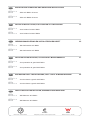
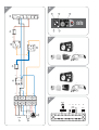
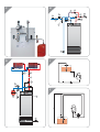
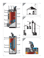
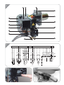
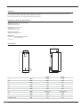
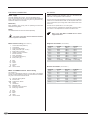
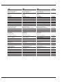
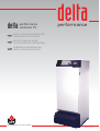
delta
performance
ventouse FV
EN
INSTALLATION OPERATING AND
SERVICING INSTRUCTIONS
FR
NOTICE D’INSTALLATION,
D’UTILISATION ET D’ENTRETIEN
NL
GEBRUIKSHANDLEIDING EN
INSTALLATIEVOORSCHRIFT
delta
performance
excellence in hot water
15/06/2004 - 664Y1600
EN
INSTALLATION OPERATING AND SERVICING INSTRUCTIONS
delta FV 35
delta FV 50
FR
NL
DE
: Avec brûleur fioul ACV BMV2
25
: Met fuel brander ACV BMV1
: Met fuel brander ACV BMV2
: Con quemador de gasoil ACV BMV2
49
: Con bruciatore a gasolio ACV BMV1
: Con bruciatore a gasolio ACV BMV2
ANLEITUNG ZUR INSTALLATION, GEBRAUCH UND WARTUNG
delta FV 35
delta FV 50
37
: Con quemador de gasoil ACV BMV1
INSTRUZIONI DELL’ INSTALLAZIONE, DELL’ USO E DI MANUTENZIONE
delta FV 35
delta FV 50
13
: Avec brûleur fioul ACV BMV1
NOTICIAS DE INSTALACIÓN, UTILIZACIÓN Y MANTENIMIENTO
delta FV 35
delta FV 50
IT
: With ACV BMV2 oil burner
GEBRUIKSHANDLEIDING EN INSTALATIEVOORSCHRIFT
delta FV 35
delta FV 50
ES
: With ACV BMV1 oil burner
NOTICE D’INSTALLATION, D’UTILISATION ET D’ENTRETIEN
delta FV 35
delta FV 50
1
: Mit Ölbrenner ACV BMV1
: Mit Ölbrenner ACV BMV2
EN ISO 9002 : 1994 Certification
Safety Quality License for boiler and pressure vessel
Watermark Licence - AS 3498
61
A
B
1
5
N T1 T2 S3 B4
L1
Br
Br
B
Y/Gr
7
4
2
3
Br
1
1
9
Or
C
2
C
B
B
Or
3
4
B
Br
D
B
Or
B
Br
Y/Gr
2
L1
N T1 T2 S3
L1
N T1 T2 S3
E
SQK 349
B5
B9
B3
B2
QAAD50
(QAAD70) QAC32
B
R
B
Y/Gr
Y/Gr
Br
P1
QAD22
bl bk br
230V-50 Hz
6A
5
20
19
18
17
16
15
14
13
12
11
10
20
19
18
17
16
15
14
13
12
11
10
9
8
9
8
7
6
7
6
5
4
5
4
3
2
3
2
1
6
1
8
N Y2 Y1
P1
B5
B9
B3
B2
F
H
4
5
2
3
7
5
10
6
1
9
G
I
8
8
H
4
3
2
1
J
5
6
7
H
9
11
8
K
L
B 23
F
1
2
3
E
4
15
A
C
14
B
D
5
13
6
M
C 13 / C 33
C33
120
150 min.
12
C43
11
7
C13
10
9
8
2 m min.
C13
16
26
17
N
25
18
19
24
23
20
22
21
O
1
2
4
5
6
16
15
7
3
8
14
13
9
12
10
11
P
6
M
1~
QRD
Q
BV1
OH
4 10 1
1
Br
B
Br
Y/Gr
B
Br
N
Y/Gr
Bk
3
Y/Gr
N
B
Y/Gr
Br
B
W
Bk
3 N 8
Y/Gr
N
B
4
B
12 11
Br
A1
M
Z
R
X1
B4 S3 T2 T1 N
L1
B4 S3 T2 T1 N
L1
X2
INSTALLATION, OPERATING
AND SERVICING INSTRUCTIONS
performance
balanced flue
FV 35
with ACV
BMV(K)1
oil burner
FV 50
with ACV
BMV(K)2
oil burner
EN
1
INDEX
INTRODUCTION
INTRODUCTION
2
INTENDED USERS OF THESE INSTRUCTIONS
Intended users of these instructions
Symbols
Applicable standards
Warnings
2
2
2
2
These instructions are intended for:
- specifying engineers
- installing engineers
- users
- servicing technicians
DESCRIPTION
3
Overview
Description of operation
Construction features
Boiler captions
3
3
3
3
TECHNICAL SPECIFICATION
4
General
Maximum operating conditions
Dimensions
Domestic hot water performance
General features
4
4
4
5
5
INSTALLATION
6
Boiler room
Chimney connections
Heating connections
Hot water connections
Controller kits
Electrical connection
Oil supply
6
6
7
7
7
8
8
BURNER FEATURES
9
ACV BMV1 and BMV2 oil burners
ACV BMV1 and BMV2 burner factory settings
ACV BMV1 and BMV2 burner captions
9
9
9
SYMBOLS
STARTUP
10
Filling the hot water and heating circuits
Commissioning ACV BMV1 and BMV2 burners
10
10
SERVICING
10
Recommendation
Servicing the boiler
Servicing the safety devices
Servicing the burner
Emptying the boiler
10
10
10
10
10
USER GUIDE
11
Using the boiler
Resetting ACV BMV1 and BMV2 burners
11
12
The following symbols are used in these instructions:
Essential instruction for operating the system
correctly.
Essential instruction for personal safety and
environmental protection.
Danger of electrocution.
Risk of burns.
APPLICABLE STANDARDS
The products have received the "EC" certificate of compliance with
standards of individual countries (European Directive 92/42/EEC,
"efficiency"). These products also have the Belgian OPTIMAZ mark.
WARNINGS
These instructions are an integral part of the equipment to which
they refer and must be supplied to the user.
The product must be installed and serviced by qualified heating
engineers, in compliance with the prevailing standards.
ACV accepts no liability for any damage resulting from incorrect
installation or from the use of components or fittings not specified by
ACV.
Failure to observe instructions regarding tests
and test procedures can result in personal injury or
pollution risks.
Note:
ACV reserves the right to modify the technical specifications and
components of its products without prior notice.
EN
2
DESCRIPTION
OVERVIEW
Combustion gas circuit
• Combination boiler (central heating and domestic hot water).
The combustion gas circuit is protected by a high temperature
resistant paint. It is composed of:
• TANK-IN-TANK indirect storage type domestic hot water production.
• Equipment required: a hydraulic connection kit for the heating
circuit (available as an option).
• The control panel comprises an on/off switch, adjustable
thermostat, thermometer, Summer/Winter selector and knockout
for fitting the ACV integrated control system (optional).
• The Delta Performance FV can be connected as a balanced flue
system with a type C concentric adapter…, or with a type B23
adapter directly to the chimney.
• The Delta Performance FV 35 with a fixed output of 35 is fitted
with the ACV BMV1 oil burner.
• The Delta Performance FV 50 with a fixed output of 50 is fitted
with the ACV BMV2 oil burner.
DESCRIPTION OF OPERATION
The "Tank-in-Tank" concept
The Delta Performance balanced flue series differs from traditional
hot water generators because of its ring-shaped tank immersed in
the primary fluid contained in the outer body. When there is a
demand for heat from the central heating system or the domestic hot
water system, the potentiometer starts the burner. The combustion
gases quickly heat up the primary fluid, creating a natural circulation
around the tank.
Domestic hot water heated indirectly
This circulation facilitates heat exchange between the primary fluid
and the domestic water, which takes place all over the tank surface.
The corrugations on the inner and outer shells of the ring-shaped
tank further boost the area of heat exchange and speed up the
heating process of the domestic water.
Easy setting with safety assured
With a single command, the water temperature of both the primary
circuit and the hot water circuit is set by the adjustable thermostat
situated under the tank in the primary circuit.
A cut-off thermostat, placed on top of the boiler, automatically cuts
out the burner when the water temperature in the primary circuit
reaches 95 °C. A manually reset safety thermostat shuts off the
burner if the temperature reaches 103 °C.
• Flue pipes. Delta Performance balanced flue models have 8 steel
flue pipes with an internal diameter of 64 mm. Each pipe is fitted
with a special steel baffle designed to improve heat exchange and
reduce flue gas temperature.
• Combustion chamber. The sealed combustion chamber is water
cooled.
Insulation
The boiler body is fully insulated by rigid polyurethane foam with a
high thermal insulation coefficient, sprayed on without the use of
CFCs.
Jacket
The boiler is covered by a steel jacket which has been scoured and
phosphated before being stove enamelled at 220 °C.
BOILER CAPTIONS
1.
2.
3.
4.
5.
6.
7.
8.
9.
10.
11.
12.
13.
14.
15.
16.
17.
18.
19.
20.
21.
22.
23.
24.
25.
26.
(see illustration K)
Control panel
Removable jacket top
Flue reduction collar
Measuring unit
CFC-free polyurethane foam insulation
Inner ring-shaped domestic hot water tank
Side panel
Base
Burner and burner chamber plate cover
Burner chamber plate
Control thermostat bulb
Removable front panel
Tube supplying air to venturi
Manual reset safety thermostat - 103 °C
Cut-off thermostat bulb - 95 °C
Balanced flue connection unit
Heating return
Domestic cold water inlet
Inner ring-shaped domestic hot water tank
Combustion chamber
Boiler drain
Lower heating return
Flue pipes
Turbulators
Domestic hot water outlet
Central heating flow pipe
CONSTRUCTION FEATURES
Corps externe
The outer body containing the primary fluid is made of thick
STW 22 steel.
"Tank-in-Tank" type exchanger accumulator
The ring-shaped inner tank with its large heating surface for
producing domestic hot water is built of Chrome/Nickel 18/10
stainless steel. It is corrugated over its full height by an exclusive
production process and entirely argon arc welded by the TIG
(Tungsten Inert Gas) method.
EN
3
TECHNICAL SPECIFICATION
GENERALE
The units are delivered fully assembled, tested and packed on a timber base with shockproof edges and protected by heat-shrunk plastic
film. On reception and after unpacking, check the equipment for damage.
For transport purposes, refer to the weights and dimensions given below.
MAXIMUM OPERATING CONDITIONS
Maximum service pressure (tank full of water)
- Primary circuit: 3 bar
- Secondary circuit: 10 bar
Test pressure (tank full of water)
- Primary circuit: 4.5 bar
- Secondary circuit: 13 bar
Operating temperature
- Maximum temperature: 90 °C
Water quality
• Chlorides: < 150 mg/l (Stainless steel 304)
< 2000 mg/l (Duplex)
• 6 ≤ ph ≤ 8
DIMENSIONS
F
B
G
C
H
A
E
D
4
FV/35
FV/50
A
mm
1585
1830
B
mm
390
390
C
mm
200
200
D
mm
542
542
E
mm
125
125
F
mm
645
645
G
mm
80/80/125
100/100/150
H
mm
1610
1880
I
mm
800
800
Kg
182
220
Weight empty
EN
I
TECHNICAL SPECIFICATION
DOMESTIC HOT WATER PERFORMANCE
FV/35
FV/50
Operating at 80 °C
Peak delivery at 40 °C (≤ T = 30 °C)
L/10’
283
377
Peak delivery at 40 °C (≤ T = 30 °C)
L/60’
1024
1485
L/h
920
1352
Initial heating time
minutes
20
13
After drawing off 140 L at 45° C
minutes
10
8
FV/35
FV/50
Continuous delivery at 40 °C (≤ T = 30 °C)
Tank refill time at 60 °C
GENERAL FEATURES
Input
L/10’
34.9
50
Output
L/60’
32.62
46.75
Maintenance loss at 60 °C as % of rated value
%
0.8/0.7
0.6/0.45
Total capacity
L
127
162
Primary capacity
L
62
82
Heating connection
Ø
1”
1”
Domestic hot water connection
Ø
3/4”
3/4”
Hot water tank heat exchange surface
2
m
1.99
2.46
Combustion efficiency
%
94.7
93.5
Average CO2
%
13
13
14.8
21.2
Mass rate of combustion products
g/sec.
EN
5
INSTALLATION
BOILER ROOM
Chimney connection type: B23
Important
The boiler is connected to the chimney by a metal pipe
rising at an angle from the boiler to the chimney.
• Keep vents free at all times.
• Do not store inflammable products in the boiler room.
• Take care not to store corrosive products near the boiler, such as
paints, solvents, chlorine, salt, soap and other cleaning products.
Access
The boiler room must be large enough to allow good access
to the boiler. The following minimum distances (mm) are required
around the boiler:
-
front
behind
sides
above
500
150
100
700
(See illustration L)
Un raccord de cheminée est nécessaire.
A.
B.
C.
D.
E.
F.
Ventilation haute
Ventilation basse
Régulateur de tirage
Regard de visite
Hauteur de la cheminée tubée
Diamètre de la cheminée
FV/35
FV/50
Chimney
Ventilation
E = 5 m Ø min. F
mm
213
236
E = 10 m Ø min. F
mm
179
199
E = 15 m Ø min. F
mm
162
179
The boiler room must be fitted with top and bottom vents as shown
in illustration "L".
The table below is an example compliant with the Belgian
standard.
FV/35
FV/50
Ventilation
Min. fresh air requirement
m3/h
63
90
Top vent (A)
dm2
1.5
1.5
Bottom vent (B)
dm
2
1.5
2
Ø
80
100
Draught regulator (C)
Note:
(B) and (C) only for B23 type connections
Note:
Since the regulations vary from one country to
another, the table above is given for information only.
Due to the high efficiency of our boilers, the flue gases
are released at high temperature.
Therefore there is a risk of condensation in these flue
gases, which could damage some chimneys.
To avoid this risk, it is strongly recommended to line
the chimney.
Contact your installer for more information.
Chimney connection type: C…
(see illustrations M and N)
For other countries, refer to their regulations.
Base
The base on which the boiler rests must be made of noncombustible
materials.
• C 13 : concentric horizontal connection
• C 33 : concentric vertical connection
• C 43 : Concentric chimney connection
Maximum length for concentric type : 6 metres
CHIMNEY CONNECTIONS
IMPORTANT
Boilers must be installed by a qualified heating
engineer, in accordance with the prevailing local
standards and regulations.
The chimney diameter must not be less than the
diameter of the boiler connection.
EN
6
Note:
A pipe bend of 90° = an equivalent length of one metre
There should be a drain outlet close to the boiler to
prevent chimney condensates entering the boiler.
To prevent condensation water running out of the
terminal, all horizontal pipes should slope down to the
boiler.
INSTALLATION
IMPORTANT
As a safety measure against burns, we strongly
recommend installing a thermostatic mixer.
HEATING CONNECTION
Example of a basic circuit configuration
(see illustration G)
1.
2.
3.
4.
5.
6.
7.
8.
9.
3-way motorised mixing valve
Safety valve set to 3 bar with pressure gauge
Circulator
Non-return valve
System filling valve
Expansion tank
ACV 13 controller (see controller kit page 7)
Central heating isolating valve
Drain cock
Hydraulic kit + ACV heating kit
(see illustration F)
ACV offers an optional pre-assembled circulation kit comprising:
- a circulator.
- a 3-way manual motorisable valve.
- connecting pipes including a second optional circuit.
- two isolating valves.
- adapters for mounting safety valve with pressure gauge and filling
valve to right or left of expansion tank. The expansion tank is not
included.
Optional fittings available
Safety unit
Ø 3/4”
Pressure reducer
Ø 3/4“
Thermostatic mixing valve
Ø 3/4”
Expansion tank
5 litres
CONTROLLER KITS
KIT 1: ACV 13.00 / Basic
(see illustration C)
Pressure reducer
Basic kit for regulating flow temperature according to weather
conditions.
It comprises: temperature regulator with analogue timer, water
temperature detector (-30°/130 °C), outside temperature detector
(-30°/50 °C), 230V - 3 spindle servomotor SQY 31 and intermediate
socket.
If the water mains pressure is greater than 6 bar, a pressure
reducer calibrated to 4.5 bar must be fitted.
KIT 2: ACV 13.00 / Standard
HOT WATER CONNECTION
Safety unit
The tank safety unit must be ACV approved and calibrated to 7 bar.
The valve discharge must be connected to the sewer drain.
Hot water expansion tank
Installing a hot water expansion tank avoids any risk of pressure
surges due to water-hammer or pressure variations.
Hot water circulation
If the tank is situated a long way from the point of use, then
installing a closed return circuit can provide a faster supply of hot
water always available.
Example of connection with thermostatic valve
(see illustration H)
1.
2.
3.
4.
5.
6.
7.
8.
9.
10.
11.
Safety unit
Pressure reducer
Thermostatic mixing valve
Hot water circulator
Non-return valve
Hot water type expansion tank
Cold water feed valve
Drawoff tap
Drain cock
Bleed valve
Isolating valve
(see illustration D)
Basic kit for regulating flow temperature according to weather
conditions.
It comprises: temperature regulator with analogue timer, water
temperature detector (-30°/130 °C), outside temperature detector
(-30°/50 °C), 230V - 3 spindle servomotor SQY 349 and intermediate
socket.
Wiring diagram of ACV controller kits
(see illustration E)
B2.
B9.
B5.
P1.
Y1/Y2/N.
bl.
n/z.
br.
Temperature probe
Outside temperature probe
Analogue/digital room thermostat
Central heating pump
Mixer valve (SQK 349)
Blue N
Black Y2
Brown Y1
EN
7
INSTALLATION
ELECTRICAL CONNECTION
OIL SUPPLY
Power supply
System construction and installation must be in accordance with
DIN 4755. Local regulations must be followed.
The boiler operates with a 230 V - 50 Hz single phase supply.
An on-off mains switch box with 6 A fuses must be fitted outside the
boiler to allow power to be shut off during servicing and before any
repairs are carried out on the boiler.
Conformity
Boiler installation must comply with the prevailing local technical
standards and legislation.
Safety
Oil pipes must be brought sufficiently close to the burner so that the
tubes can be connected without strain. On the aspiration side of the
line, fit a filter with a quick closing valve. Install a check valve on the
return line.
The Burner can operate with a 1 or 2 line system.
In series, the burner is designed to operate with a two-line system.
The vacuum in the aspiration line should not exceed 0.4 bar.
The stainless steel tank must be earthed separately.
Refer to the ACV BMV1 and BMV2 burner manual
supplied with them.
The power to the boiler must be switched off before
any work is carried out.
Boiler electrical wiring
1.
2.
3.
4.
5.
6.
7.
8.
9.
10.
B.
Br.
Gr.
Or.
R.
Y/Gr.
(see illustration A)
Control thermostat (60/90 °C)
On/off switch
Summer/winter selector
Safety thermostat (103 °C max.)
Boiler power connection
Heating circulator connection
Burner connection
Room thermostat
Cut-off thermostat (95 °C)
Boiler power plug
Blue
Brown
Green
Orange
Red
Yellow / Green
BMV1 and BMV2 oil burner electric wiring
(see illustration P)
The burner is supplied with power by a 3-core cable, to be plugged
into the connector situated on the burner. Instructions for connection
are given in the burner technical manual.
A1.
M.
QRB.
OH.
Z.
BV1.
X1.
X2.
Automatic igniting device
Burner motor
Photoelectric resistor
Heater
Transformer
Magnetic valve
Burner Euro plug connector
Boiler plug connector
B.
Br.
Bk.
W.
Y/Gr.
Blue
Brown
Black
White
Yellow / Green
EN
8
Single-line installation
(see illustration I)
Height H
4.0 m
3.5 m
3.0 m
2.5 m
2.0 m
1.5 m
1.0 m
0.5 m
Ø 6 mm
100 m
100 m
100 m
100 m
100 m
197 m
165 m
132 m
Ø 6 mm
100 m
100 m
197 m
181 m
165 m
149 m
132 m
116 m
Ø 8 mm
100 m
100 m
100 m
100 m
100 m
177 m
151 m
126 m
Nozzle
uo to 2.5 Kg
uo to 5.0 Kg
uo to 10.0 Kg
Dual-line installation
Height H
0.0 m
0.5 m
1.0 m
1.5 m
2.0 m
2.5 m
3.0 m
3.5 m
(see illustration J)
Ø 6 mm
17 m
15 m
13 m
11 m
19 m
17 m
15 m
13 m
Ø 8 mm
53 m
47 m
41 m
34 m
28 m
22 m
15 m
19 m
Ø 10 mm
100 m
100 m
199 m
184 m
168 m
153 m
137 m
122 m
BURNER FEATURES
ACV BMV1 AND BMV2 OIL BURNERS
ACV BMV1 AND BMV2 BURNER CAPTIONS
Description
(see illustration O)
For the Delta Performance oil-fuelled balanced flue model, we have
opted for the all-new technology of the ACV BMV1 and BMV2 oil
burner, manufactured from high quality components combining
performance with perfect combustion.
CO2 chart for the ACV BMV1 and BMV2 burner
14 %
% CO2
13,5 %
13 %
12,5 %
1.
2.
3.
4.
5.
6.
7.
8.
9.
10.
11.
12.
13.
14.
15.
16.
Control unit
Nozzle line protection
Warning lamp
Electric plug connector
Attachment bracket
Burner blast tube
Ignition unit
High tension ignition cable
Oil pump
Oil aspiration line connection (circuit with return only)
Oil return connection
Motor condenser
Motor
Pump / nozzle connecting pipe
Burner casing
Nozzle line adjustment screw
12 %
-10
0
10
20
30
40
Outside temperature
ACV BMV1 AND BMV2
BURNER FACTORY SETTINGS
FV/35
FV/50
BMV1
BMV2
kW
34.9
50
gal/h
0,75
1.25
60°H
60°H
Kg/h
2.95
4.22
bar
11.8
9.5
0 - 0.5
0 - 0.5
Burner
Input
Nozzle
Nozzle angle
Oil flow
Pump pressure
Flue gas index
Air reducer
%
37
60
Air inlet
%
90
90
3.5 - 4
3.5 - 4
mm
10
10
Kg
14.5
14.5
Nozzle line pressure
Nozzle line
Weight
mbar
WARNING: Set the % of CO2 as per the data in the diagram above
EN
9
STARTUP
FILLING THE DOMESTIC HOT WATER AND
HEATING CIRCUITS (see illustrations B, G et H)
IMPORTANT
The hot water tank must be pressurised before the
heating circuit is filled.
1. Fill the domestic hot water circuit and bring it up to pressure.
2. Fill the heating circuit taking care not to exceed the 2 bar
pressure limit.
3. Vent the air from the top of the boiler.
4. After venting the air from the system, bring the pressure up to
the static head plus 0.5 bar: 1.5 bar = 10m -2 bar = 15 m.
5. Check the power connection, the boiler room ventilation, and
ensure that there are no leaks in the flue gas discharge pipes.
6. Set the boiler thermostat to between 60 and 90 °C.
7. Set the Summer/Winter selector to the desired position.
SERVICING
RECOMMENDATION
ACV advises that boilers should be serviced at least once a year.
The burner must be serviced and tested by a competent engineer.
SERVICING THE BOILER
(see illustration K)
1. Switch off the power at the mains switch outside the boiler and
shut off the oil supply.
2. Set the on/off switch on the control panel to the OFF position.
3. Remove the top cover of the boiler (2) and take off the top of the
chimney reduction (3).
5. Remove the turbulators (23) from the flue pipes (22) for cleaning.
Change them if in poor condition.
6. Unscrew the burner chamber plate (10).
7. Brush the flue pipes (22).
8. Clean the burner chamber (18) and the burner.
9. Check the condition of the burner chamber plate insulation.
SERVICING THE SAFETY DEVICES
- Check that all thermostats and safety devices are working
properly : boiler thermostat, cut-off thermostat and manually reset
safety thermostat.
- Test the safety valves on the central heating and hot water circuits.
8. Switch the on/off switch to the ON position.
9. Check the oil supply (and return).
10. Carry out the required venting, measurement and setting
procedures.
SERVICING THE BURNER
Refer to the ACV BMV1 and BMV2 burner manual supplied with them.
EMPTYING THE BOILER
STARTING ACV BMV1 AND BMV2 BURNERS
Refer to the ACV BMV1 and BMV2 burner manual supplied with them.
Water flowing out of the drain cock is extremely
hot and can cause severe burns.
Keep people away from discharges of hot water.
Emptying the heating circuit
(see illustration G)
1. Set the on/off switch on the control panel to the OFF position,
turn off the power at the external mains switch and close the oil
feed valve.
2. Close the isolating valves (8).
3. Connect a hose to the drain cock (9).
4. Open the drain cock to empty the primary circuit.
Emptying the hot water circuit
(see illustration H)
1. Set the on/off switch on the control panel to the OFF position,
turn off the power at the external mains switch and close the oil
feed valve.
2. Lower the pressure in the heating circuit until the pressure
gauge indicates zero bar.
3. Close the valves (7 and 11).
4. Open valves (9) and (10) (first 9 then 10).
5. Let the water empty into the drain .
For the tank to be emptied, valve (9) must be situated
at ground level.
EN
10
USER GUIDE
USING THE BOILER
Safety valve (heating)
Have your system serviced every year by a qualified
heating engineer. If the boiler is subject to heavy
usage, it may need more frequent servicing. If this is
the case, ask your installer for advice.
Starting the burner:
In normal operation, the burner starts automatically
whenever the boiler temperature falls below the set
temperature.
If water flows from one of the safety valves, shut off the boiler and
call your heating engineer.
A monthly inspection is recommended:
Lift the lever on the emptying device for a few seconds to ensure that
the safety valve is working properly.
If a fault occurs after this short trial, call the installing
engineer.
Safety unit (domestic hot water)
Before doing any work on the boiler, switch off the
power at the mains switch installed in the boiler room
by the electrician.
On the control panel, switch off the ON/OFF switch.
Getting to know the control panel
(see illustration B)
A monthly inspection is recommended.
Lift the lever on the emptying device for a few seconds to ensure that
the safety unit is working properly.
If a fault occurs after this short trial, call the installing
engineer.
Water flowing out of the safety valve or safety
unit may be extremely hot and can cause very
serious burns.
The user should not access the components inside
the control panel.
1. Control thermostat - 60 to 90 °C
When the boiler is used only to produce domestic hot water, the
temperature can be set between 60 and 90 °C. If the boiler is used
for both hot water and heating, the control thermostat will, as a
general rule, be set to 80 °C to ensure optimum operating conditions.
2. ON/OFF switch
Used to start and stop the boiler.
3. Summer/winter selector
Starts and stops the heating pump (if fitted).
4. Thermometer
Shows the boiler temperature in the primary circuit.
The temperature should not exceed 90 °C. If it does, switch off the
boiler and check the thermostat settings. If there is a fault, call a
heating engineer.
5. Controller
See the user instructions supplied with the unit if you have chosen
this option.
6. Burner reset
7. Burner indicator lamp
EN
11
USER GUIDE
RESETTING ACV BMV1 AND BMV2 BURNERS
(see illustration Q)
If the burner is not working:
1. Remove the protective cover of the burner.
2. If the red light is lit, press the button to start the burner.
3. If the burner lights, replace the cover.
If the burner does not operate, switch off the power
before removing the front cover panel.
4. Reset the safety thermostat on top of the boiler. (see illustration R).
Wait until the boiler temperature is below 60 °C then
replace the front cover panel.
5. If the burner lights, replace its cover.
6. If the fault persists, notify the installing engineer.
Starting the burner
In normal operation, the burner starts automatically whenever the
boiler temperature falls below the set temperature.
To ensure your system operates properly, have it
professionally serviced once a year before the central
heating season begins.
EN
12
REPLACEMENT PARTS / PIECES DETACHEES / WISSELSTUKKEN
EN
FR
NL
Burner
Brûleur
Brander
See Oil burner instructions
Voir notice du brûleur fioul
Zie handleiding van de stookoliebrander
BMV(K)1 / BMV(K)2
BMV(K)1 / BMV(K)2
BMV(K)1 / BMV(K)2
Casing
Jaquette
Mantel
Front panel
Face avant
Voorpaneel
21473397
Left panel
Face latérale gauche
Links zijpaneel
21472397
Right panel
Face latéral droite
Rechts zijpaneel
21471397
Rear panel
Face arrière
Achterpaneel
21474397
Large top cover
Grand couvercle supérieur
Groot deksel bovenaan
21475397
Small top cover
Petit couvecle supérieur
Klein deksel onderaan
21478397
Burner hood
Coiffe de la porte foyère
Kap van de vuurhaarddeur
21476397
Control panel
Tableau
Schakelpaneel
21477342
Electrical control panel
Tableau électrique
Elektrisch schakelbord
Control panel + wiring
Tableau de commande + câblage
Bedieningspaneel + bekabeling
Summer/Winter selector
Interrupteur Eté/Hiver
Zomer/winter-schakelaar
54766007
Jumper plug (T1 - T2)
Prise pontée (T1 - T2)
Brugstekker (T1-T2)
257F1026
Accessories
Accessoires
Accessoires
Deep tube PVCC
Plonge PVCC
PVCC-buis
Ø 19,5 mm / L. 800 mm
Ø 19,5 mm / L. 800 mm
Ø 19,5 mm / L 800 mm
Bulb for thermostat
Doigt de gant laiton
Messing voeler huls
Ø 1/2” / L. 100 mm
Ø 1/2” / L. 100 mm
Ø 1,2" / L 100 mm
63438001
Spring clips FPL3017
Clips ressort FPL3017
Veerclips FPL3017
47405006
Baffle, Mignon DN
Chicane Mignon DN
Retarders Mignon DN
50423352
Balanced flue adapter
Adaptateur ventouse
Concentrische aansluiting
Ø 80/125 mm
Ø 80/125 mm
Ø 80/125 mm
507F3038
Cerablanket isulation
Isolation cérablanket
Isolatie Cerablanket
51305000
Condensate collector with
Récupération des condensats
Meetelement met
measuring devices
avec éléments de meusure
condensopvang
Flexible Master-Neo
Flexible Master-Neo
Flexibele slang Master-Neo
Ø 80 / L. 2 m
Ø 80 / L. 2 m
Ø 80 /L 2 m
537D6137
Control thermostat
Thermostat de réglage
Regelthermostaat
54322000
Reset thermostat
Thermostat à réarmement
Thermostaat voor de herinschakeling
54764010
Drain cock Ø 1/2”
Robinet de vidange Ø 1/2”
Leegloopkraan Ø 1/2 "
55426001
Chiney reducing joint Ø 325
Joint réduction de cheminée Ø 325
Dichting schouwreductiestuk Ø 325
557A0016
Rubber seal Ø 80
Joint caoutchouc Ø 80
Rubberen dichting Ø 80
557D2003
Codes
24614064
49410045
537D6068
37
www.acv-world.com
excellence in hot water
INTERNATIONAL
FRANCE
SLOVAK REPUBLIC
ACV international n.v
KERKPLEIN, 39
B-1601 RUISBROEK - BELGIUM
TEL.: +32 2 334 82 20
FAX: +32 2 378 16 49
E-MAIL: [email protected]
ACV FRANCE sa
31, RUE AMPERE - Z.I MI - PLAINE
F-69680 CHASSIEU - FRANCE
TEL.:+33 4 72 47 07 76
FAX:+33 4 72 47 08 72
E-MAIL: [email protected]
ACV SLOVAKIA s.r.o.
PLUHOVÁ 49
831 04 BRATISLAVA - SLOVAK REPUBLIC
TEL.:+421 2 444 62 276
FAX:+421 2 444 62 275
E-MAIL: [email protected]
BELGIUM
ITALIA
SLOVENIA
ACV BELGIUM nv/sa
KERKPLEIN, 39
B-1601 RUISBROEK-BELGIUM
TEL.: +32 2 334 82 40
FAX: +32 2 334 82 59
E-MAIL: [email protected]
ACV ITALIA
VIA PANA 92
I-48018 FAENZA (RA) - ITALIA
TEL.:+39 0546 64 61 44
FAX:+39 0546 64 61 50
E-MAIL: [email protected]
ACV D.O.O. SLOVENIA
OPEKARNA 22b
1420 TRBOVLJE - SLOVENIA
TEL.:+386 356 32 830
FAX:+ 386 356 32 831
E-MAIL: [email protected]
CHILE
NEDERLAND
UK
ALBIN TROTTER Y ACV LTDA
SAN PABLO 3800
QUINTA NORMAL - SANTIAGO - CHILE
TEL.:+56 2 772 01 69
FAX:+56 2 772 92 62/63
E-MAIL: [email protected]
ACV NEDERLAND bv
POSTBUS 350
NL-2980 AJ RIDDERKERK - NEDERLAND
TEL.:+31 180 42 10 55
FAX:+31 180 41 58 02
E-MAIL: [email protected]
ACV UK Ltd
ST. DAVID’S BUSINESS PARK
DALGETY BAY - FIFE - KY11 9PF
TEL.:+44 1383 82 01 00
FAX:+44 1383 82 01 80
E-MAIL: [email protected]
CZECH REPUBLIC
POLAND
USA
ACV CR SPOL. s.r.o
NA KRECKU 365
CR-109 04 PRAHA 10 - CZECH REPUBLIC
TEL.:+420 2 720 83 341
FAX:+420 2 720 83 343
E-MAIL: [email protected]
ACV POLSKA sp. z.o.o.
UL.WITOSA 3
87 - 800 WWOCWAWEK - POLAND
TEL.:+48 54 412 56 00
FAX:+48 54 412 56 01
E-MAIL: [email protected]
TRIANGLE TUBE PHASE III
FREEWAY CENTER - 1 TRIANGLE LANE
BLACKWOOD NJ 08012 - USA
TEL.:+1 856 228 8881
FAX:+1 856 228 3584
E-MAIL: [email protected]
DEUTSCHLAND
PORTUGAL
ACV WÄRMETECHNIK GMBH & CO KG
GEWERBEGEBIET GARTENSTRASSE
D-08132 MÜLSEN OT ST. JACOB - DEUTSCHLAND
TEL.:+49 37601 311 30
FAX:+49 37601 311 31
E-MAIL: [email protected]
BOILERNOX LDA
RUA OUTEIRO DO POMAR
CASAL DO CEGO, FRACÇÃO C,
PAVILHÃO 3 - MARRAZES
2400-402 LEIRIA - PORTUGAL
TEL.:+351 244 837 239/40
FAX:+351 244 823 758
E-MAIL: [email protected]
ESPAÑA
ACV ESPAÑA
C/DE LA TEIXIDORA, 76
POL. IND. LES HORTES
E-08302 MATARÓ - ESPANA
TEL.:+34 93 759 54 51
FAX:+34 93 759 34 98
E-MAIL: [email protected]
RUSSIA
ACV RUSSIA
1/9, MALYI KISELNYI
103031 MOSCOW - RUSSIA
TEL.:+7 095 928 48 02 / +7 095 921 89 79
FAX:+7 095 928 08 77
E-MAIL: [email protected]
ARGENTINA
DENMARK
MOLDAVIA
TECNOPRACTICA
ALFEREZ BOUCHARD 4857
1605 CARAPACHAY - BUENOS AIRES
TEL.: +54 11 47 65 33 35
FAX: +54 11 47 65 43 07
E-MAIL: [email protected]
VARMEHUSET
FRICHSVEJ 40 A
8600 SILKEBORG - DENMARK
TEL.:+45 86 82 63 55
FAX:+45 86 82 65 03
E-MAIL: [email protected]
STIMEX - PRIM S.R.L.
STR BUCURESTI, 60A
2012 CHISINAU - MOLDAVIA
TEL.:+37 32 22 46 75
FAX:+37 32 27 24 56
E-MAIL: [email protected]
AUSTRALIA
ESTONIA
NEW ZEALAND
HUNT HEATING PTY LTD
10 GARDEN BOULEVARD
3172 VICTORIA - AUSTRALIA
TEL.: +61 3 9558 7077
FAX: +61 3 9558 7027
E-MAIL: [email protected]
BRAZIL
SIMETAL INDUSTRIA E COMERCIO
DE FERRAMENTAS LTDA
RUA GERSON ANDREIS 535
95112 - 130 CAXIAS DO SUL - BRAZIL
TEL.: +55 54 227 12 44
FAX: +55 54 227 12 26
E-MAIL: [email protected]
BULGARIA
PROXIMUS ENGINEERING LTD
7 BIAL KREM STR.
9010 VARNA - BULGARIA
TEL.:+359 52 500 070
FAX:+359 52 301 131
E-MAIL: [email protected]
CHINA
BEIJING HUADIAN HT POWER TECHNOLOGY
DEVELOPMENT CO. LTD
ROOM B-912, TOWER B, COFCO PLAZA
N°. 8, JIANGUOMENNEI AVENUE
BEIJING 100005 - PEOPLE’S REPUBLIC OF CHINA
TEL.:+86 10 652 30 363/393 EXT 101
FAX:+86 10 652 27 071
E-MAIL: [email protected]
SHANGHAI COOLTECH LTD
14/F E. CHINA MERCHANTS PLAZA
N°. 333 CHENGDU ROAD (N)
200041 SHANGHAI - CHINA
TEL.:+86 21 52 98 11 22 - 820
FAX:+86 21 52 98 13 58
E-MAIL: [email protected]
TERMOX AS
TAHE 112A
51013 TARTU - ESTONIA
TEL.:+372 736 73 39
FAX:+372 736 73 44
E-MAIL: [email protected]
ENERGY PRODUCTS INTERNATIONAL
8/10 BELFAST PLACE
PO BOX 15058 HAMILTON - NEW ZEALAND
TEL.:+64 7 847 27 05
FAX:+64 7 847 42 22
E-MAIL: [email protected]
GREECE
ÖSTERREICH
ESTIAS
MARASLI STREET 7
54248 THESSALONIKI - GREECE
TEL.:+30 23 10 31 98 77 / +30 23 10 32 03 58
FAX:+30 23 10 31 97 22
E-MAIL: [email protected]
PROTHERM HEIZUNGSTECHNIK Gmbh
TRAUNUFERSTRASSE 113
4052 ANSFELDEN - ÖSTERREICH
TEL.:+43 7229 804 82
FAX:+43 7229 804 92
E-MAIL: [email protected]
ÎLE MAURICE
ROMANIA
SOTRATECH
29, RUE MELDRUM
BEAU BASSIN - ÎLE MAURICE
TEL.:+230 46 76 970
FAX:+230 46 76 971
E-MAIL: [email protected]
SC TRUST EURO THERM SA
D.N PIATRA NEAMT - ROMAN
km 2 C.P 5 O.P 3 jud. Neamt
5600 PIATRA NEAMT - ROMANIA
TEL.:+40 233 20 62 06
FAX:+40 233 20 62 00
E-MAIL: [email protected]
LITHUANIA
UAB “GILIUS IR KO”
SAVARNORIU PR. 192
3000 KAUNAS - LITHUANIA
TEL.:+370 37 308 930
FAX:+370 37 308 932
TUNISIE
SO.CO.ME CHAUMAX
BOÎTE POSTALE N°44
1002 TUNIS - TUNISIE
TEL.:+216 71 78 15 91
FAX:+216 71 78 87 31
MAROC
CASATHERM
PLACE EL YASSIR
20300 CASABLANCA - MAROC
TEL.:+212 22 40 15 23
FAX:+212 22 24 04 86
UKRAINE
UKRTEPLOSERVICE LTD
PR. LAGUTENKO 14
83086 DONETSK - UKRAINE
TEL.:+38 062 382 60 47/48
FAX:+38 062 335 16 89