1
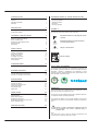
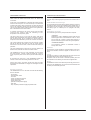
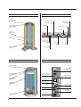
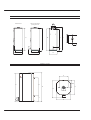
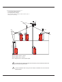
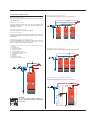
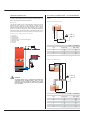
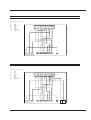
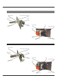
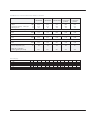
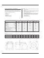
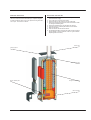
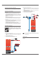
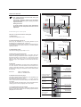
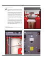
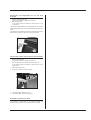
HeatMaster
Installation, Operating and
Servicing Instructions
HM 60 N / 70 N / 100 N / 150 JUMBO
HM 60 N / 70 N / 100 N
With ACV BG 2000-S premix gas burner
HM 60 N / 70 N / 100 N
With ACV BM 101 oil burner
HM 150 JUMBO
With ACV BM 151 oil burner
excellence in hot water
66400501
INDEX
INTRODUCTION
INTRODUCTION
1
INTENDED USERS OF THESE INSTRUCTIONS
Intended users of these instructions
Symbols
Applicable standards
Warnings
1
1
1
1
These instructions are intended for
- specifying engineers
- installing engineers
- end-users
- servicing engineers
DESCRIPTION
2
Operating principle
Construction features
2
2
TECHNICAL SPECIFICATION
5
Essential instruction for operating the system
correctly.
Maximum operating conditions
Burner chamber plate
Domestic hot water performances
General features
Dimensions
5
5
5
5
6
Essential instruction for personal safety or
environmental protection.
INSTALLATION
8
Danger of electrocution.
SYMBOLS
Boiler room
Chimney connections
Hot water connections
Heating connection
Oil supply connections
Electrical connections
Wiring diagram
8
8
10
11
11
12
12
COMMISSIONING
14
Filling the hot water and heating circuits
14
BURNER FEATURES
15
ACV BG 2000-S premix gas burners
ACV BM 101 and BM 151 oil burners
15
19
MAINTENANCE
20
Service intervals
Servicing the boiler
Servicing the safety devices
Servicing the burner
Draining the boiler
Spare parts
20
20
21
21
21
21
USER GUIDE
22
Using the boiler
Boiler safety shutdown
Resetting the oil burner
Resetting the BG 2000-S premix burner
Burner troubleshooting
22
23
23
23
23
SERVICE RECORD
24
The following symbols are used in these instructions:
Risk of scalding.
APPLICABLE STANDARDS
The products have received the “CE” certificate in accordance with
the standards prevailing in different countries (European Directives
92/42/EEC, “efficiency”, 90/396/EEC “gas appliances”). These
products have also received the Belgian “HR+” (gas boilers) marks
and “OPTIMAZ” (oil boilers) marks.
WARNINGS
These instructions are an integral part of the equipment to which
they refer and must be supplied to the user.
The product must be installed and serviced by qualified engineers,
in compliance with the prevailing standards.
ACV accepts no liability for any damage resulting from incorrect
installation or from the use of components or fittings not specified by
ACV.
Failure to observe instructions regarding tests and
test procedures can result in personal injury or
pollution risks.
Note:
ACV reserves the right to modify the technical specifications and
components of its products without prior notice.
1
DESCRIPTION
OPERATING PRINCIPLE
CONSTRUCTION FEATURES
The HeatMaster is a high performance, direct fired hot water storage
heater, which has indirect heat transfer due to its Tank-in-Tank
construction.
Outer body
At the heart of the HeatMaster is a stainless steel cylinder through
which the flue tubes pass. This is surrounded by a mild steel shell
containing the primary water (neutral fluid). The outer shell extends
down to the combustion chamber and even around the flue tubes.
The area of the heat transfer surface is therefore much greater than
that of standard direct fired water heaters.
TANK-IN-TANK heat exchanger
A circulating pump fitted to the primary circuit moves the water
around the tank, heating it faster and maintaining an even
temperature across the primary jacket.
Combustion gas circuit
The outer body containing the primary fluid is made of thick STW 22
steel.
The ring-shaped inner tank with its large heating surface for producing
domestic hot water is built of Chrome/Nickel 18/10 stainless steel. It
is corrugated over its full height by an exclusive production process
and entirely argon arc welded by the TIG (Tungsten Inert Gas)
method.
The combustion gas circuit is paint-protected and comprises:
The burner, either gas or oil, fires onto the primary water which
indirectly heats the stainless steel cylinder containing the DHW. As
with all Tank-in-Tanks, this is corrugated over its full height and
suspended in the HeatMaster by its hot and cold water connections.
• Flue pipes
Depending on output, HeatMaster models contain several
steel flue pipes with an internal diameter of 64 mm. Each
pipe is fitted with a baffle of special steel designed to
improve heat exchange and reduce flue gas temperature.
The cylinder expands and contracts during use and this, together
with the fact that cold water does not come into contact with the
intense heat of the burner flame, means that limescale buildup is
prevented.
• Combustion chamber
The combustion chamber on HeatMaster models is
entirely water cooled.
This scale resistant feature, along with the corrosion resistance of
stainless steel, eliminates the need for sacrifical anodes.
The HeatMaster has one very major advantage over other direct
fired water heaters - because it heats the DHW with a primary
circuit, this primary water can be used to provide central heating as
well.
By connecting two, three, four or more HeatMasters together in a
module, most hot water and heating demands can be met.
Indeed, when used in conjunction with HR and Jumbo hot water
storage tanks the Heatmaster can supply even the largest hot water
requirement.
Standard equipment
The HeatMaster 60 N / 70 N / 100 N and 150 Jumbo has the following
items as standard :
- On/off switch
- Summer/Winter switch
- Timeclock
- primary circulating shunt pump
- primary expansion vessels
- primary safety valve
- pressure and temperature gauge
- drain valve
- body completely insulated in rigid polyurethane foam
2
Insulation
The boiler body is fully insulated by rigid polyurethane foam with a
high thermal insulation coefficient, sprayed on without the use of
CFCs.
Casing
The boiler is covered by a steel jacket which has been scoured and
phosphated before being stove enamelled at 220 °C.
The jacket of the HM 150 Jumbo is delivered separately and must
be assembled on site following the instructions supplied with it.
Burner
All HeatMaster models can be fitted with pressure jet gas burners or
oil burners. The HeatMaster 60, 70 and 100 can also be fitted with the
low-NOx pre-mix BG 2000 gas burner.
DESCRIPTION
Features of HeatMaster 70 N / 100 N
Flue reduction collar
Top cover
Central heating
flow pipe
Automatic air vent
Domestic hot
water outlet
Domestic cold water inlet
Flue pipes and
turbulators
Heating circuit filling valve
with removable hose and
non-return valve
Tank-in-Tank
heat exchanger
Primary expansion vessel
Insulation
Primary shunt pump
Burner
Casing front panel
Heating return
Primary circuit
Combustion chamber
Burner chamber plate
Safety features of the HeatMaster 60 N
Control panel HeatMaster 60 N
Thermal reset high
limit thermostat
Combined temperature
and pressure gauge
Manual reset high
limit thermostat
Manual reset high
limit thermostat
Burner
lockout
indicator
Time clock
Low water
pressure switch
I
O
Primary safety valve
Primary circuit low
water pressure
indicator
Control
thermostat
ON / OFF
switch
Control thermostat
High limit cutoff
indicator
Summer / Winter switch
3
DESCRIPTION
Safety features of the HeatMaster 70 N and 100 N
Control panel HeatMaster 70 N and HeatMaster 100 N
Thermal reset high
limit thermostat
Combined temperature
and pressure gauge
Manual reset high
limit thermostat
Manual reset high
limit thermostat
Burner
lockout
indicator
Summer / Winter switch
Time clock
Low water
pressure switch
I
O
Control thermostat
Primary circuit low
water pressure
indicator
ON / OFF
switch
Control
thermostat
High limit cutoff
indicator
Primary safety valve
Safety features of the HeatMaster 150 Jumbo
Control panel HeatMaster 150 Jumbo
Primary safety valve
Mains power
electrical connection
(multi-pin plug)
Thermal reset high
limit thermostat
Combined temperature
and pressure gauge
bar
.....
Relay base
.....
.....
Manual reset high
limit thermostat
Primary circuit low
water pressure indicator
...
18
19
17
20
16
21
22
14
23
I
11
1
12
24
13
Time clock
15
2
O
10
9
3
GRASSLIN
4
8
7
6
5
Low water
pressure switch
ON / OFF switch
Fuse
Manual reset high
limit thermostat
Control thermostat
Thermal reset high
limit thermostat
Servicing socket
Control thermostat
4
(230 V ˜ 50 Hz)
TECHNICAL SPECIFICATION
MAXIMUM OPERATING CONDITIONS
BURNER CHAMBER PLATE
Maximum service pressure (tank full of water)
- Primary circuit: 3 bar
- Secondary circuit: 10 bar
The burner chamber plate has 4 threads (M 10 x 20) for attaching
the burner. It is protected from heat by a blanket insulation.
Test pressure (tank full of water)
- Primary circuit: 4.5 bar
- Secondary circuit: 13 bar
5xØ6.5(M8)
Operating temperature
- Maximum temperature: 90 °C
Ø130
Ø28
60
Water quality
• Chlorures: < 150 mg/l (304)
< 2000 mg/l (Duplex)
60
60
60
• 6 ≤ ph ≥ 8
DOMESTIC HOT WATER PERFORMANCES
HM 60 N
HM 60 N
HM 70 N
HM 70 N
HM 100 N
HM 100 N
HM 150
BM 101
BG 2000-S/60
BM 101
BG 2000-S/70
BM 101
BG 2000-S/100
JUMBO
Peak
Peak
Peak
Peak
Peak
delivery
delivery
delivery
delivery
delivery
at
at
at
at
at
40
45
60
70
80
°C
°C
°C
°C
°C
L/10’
L/10’
L/10’
L/10’
L/10’
474
378
245
193
135
474
378
245
193
135
646
543
346
268
207
646
543
346
268
207
905
777
514
343
258
905
777
514
343
258
1504
1289
870
700
540
Peak
Peak
Peak
Peak
Peak
delivery
delivery
delivery
delivery
delivery
at
at
at
at
at
40
45
60
70
80
°C
°C
°C
°C
°C
L/60’
L/60’
L/60’
L/60’
L/60’
1942
1656
1106
681
499
1942
1656
1106
681
499
2133
1794
1219
971
636
2133
1794
1219
971
636
3172
2680
1813
1226
893
3172
2680
1813
1226
893
4828
4138
2864
2131
1362
delivery
delivery
delivery
delivery
delivery
at
at
at
at
at
L/h
L/h
L/h
L/h
L/h
1835
1573
1101
791
455
1835
1573
1101
791
455
1835
1573
1067
918
580
1835
1573
1067
918
580
2776
2379
1665
1104
804
2776
2379
1665
1104
804
3989
3419
2393
1718
987
min
9
9
16
16
13
13
17
Continuous
Continuous
Continuous
Continuous
Continuous
40
45
60
70
80
°C
°C
°C
°C
°C
Reheat time at 60 °C
GENERAL FEATURES
HM 60 N
HM 70 N
HM 100 N
HM 150
JUMBO
Maximum Input
Maximum Output
Maintenance loss at 60 °C as rated value
Total capacity
Primary circuit capacity
Heating connection
Hot water connection
Hot water tank heat exchange surface
Weight empty
Pressure drop primary circuit
kW
kW
%
L
L
Ø
Ø
m2
Kg
mbar
69.9
62.5
0.57
162
82
11/2”
3/4”
2.46
220
54
69.9
63.0
0.60
239
108
11/2”
1”
3.14
270
46
107.0
96.8
0.65
330
130
11/2”
1”
3.95
320
83
154.0
139.1
0.52
645
245
DN 50
2”
5.30
530
120
5
TECHNICAL SPECIFICATION
DIMENSIONS
The units are delivered fully assembled, tested and packed on a timber base with shockproof edges and protected by heat-shrunk plastic film.
On reception and after unpacking, check the equipment for damage. For transport purposes, refer to the weight (page 5) and dimensions given
below.
A mm
B mm
C mm
D mm
E mm
F mm
G Ø mm
H mm
J mm
K mm
HM 60 N
1698
1583
538
625
540
390
150
1098
281
1665
HM 60 N BG 2000-S 60
1698
1583
538
801
540
390
150
1098
281
1665
HM 70
1743
1630
678
797
680
390
150
1289
285
1720
HM 70 N BG 2000-S 70
1743
1630
680
937
680
390
150
1289
285
1720
HM 100 N
2093
2030
680
797
680
390
150
1693
285
2120
HM 100 N BG 2000-S 100
2093
2030
680
937
680
390
150
1693
285
2120
HM 150 Jumbo
2124
2117
1020
1440
1020
600
250
1383
590
2250
HeatMaster 60 N
Without burner
With ACV BG 2000-S
premix gas burner
F
G
A
A
B
H
K
C/2
J
C
D
6
C
D
E
TECHNICAL SPECIFICATION
HeatMaster 70 N and HeatMaster 100 N
Without burner
G
With ACV BG 2000-S
premix gas burner
A
F
A
H
B
K
C/2
J
C
C
D
E
D
HeatMaster 150 Jumbo
F
A
562
H
K
C
D
G
J
E
7
INSTALLATION
BOILER ROOM
CHIMNEY CONNECTIONS
Important
•
•
•
Keep vents free at all times.
Do not store inflammable products in the boiler room.
Do not store corrosive products near the boiler, such as paints,
solvents, chlorine, salt, soap and other cleaning products.
If you smell gas, do not switch on the light or light a flame. Turn off
the mains gas tap at the meter and inform the appropriate
services immediately.
•
IMPORTANT
Boilers must be installed by an approved heating
engineer, in accordance with the prevailing local
standards and regulations.
Access
Flue size should not be less then the outlet size of the
boiler.
The boiler room must be large enough to allow good access to the
boiler. The following minimum distances are required around the boiler:
-
front
side
behind
above
500
100
150
700
mm
mm
mm
mm
Chimney connection type: B23
The boiler is connected to the chimney by a metal pipe rising at an
angle from the boiler to the chimney.
A flue disconnection piece is required.
This must be easy to remove to give access to the flue pipes when
servicing the boiler.
Ventilation
The boiler room must be fitted with top and bottom vents sized
according to the table below or to current regulations.
The table below gives an example conforming to the Belgian standards.
Ventilation
60 N
70 N
100 N
150
A.
B.
C.
D.
E.
F.
Top vent
Bottom vent
Draught regulator
Inspection window
Height of lined chimney
Chimney diameter
F
Jumbo
E
Min. fresh air
requirement
m3/h
126
126
194
Bottom
dm2
2.11
2.11
3.20
278
4.8
Top
dm2
2.0
2.0
2.0
2.0
C
A
Other countries should refer to their own standards.
B
Base
D
The base on which the boiler rests must be made of non-combustible
materials.
Chimney
minimum flue diameter
60 N
E = 5 m Ø F min. mm
E = 10 m Ø F min. mm
E = 15 m Ø F min. mm
189
159
150
70 N
100 N
150
Jumbo
189
159
150
234
178
150
286
250
250
Note:
Regulations vary from country to country therefore
the table above is intended only as a guide.
Due to the high efficiency of our boilers, the flue gasses
exit at low temperature. Accordingly, there is risk that
the flue gasses could condense, which could damage
the chimney. In order to avoid this risk, it is strongly
recommended that the chimney be lined.
8
INSTALLATION
Balanced flue boiler connection type: C
C33
120
C13
150 min.
C13: concentric horizontal connection
C33: concentric vetical connection
C53: parallel chimney connection
C63: concentric vertical connection without terminal (only in
Germany and Luxembourg).
C53
2 m min.
•
•
•
•
Maximum length concentric : 6 metres
Maximum length parallel : 12 metres
Note: a 90 degree bend = 1 metre equivalent length
A condensation drain outlet must be fitted close to the boiler to prevent condensation products from
the chimney running into the boiler.
To avoid condensation water running out of the terminal, all horizontal flue runs must fall back
towards the boiler.
9
INSTALLATION
HOT WATER CONNECTIONS
Example of parallel connection
Recommended for applications with a high continuous flow.
Pressure reducing valve
If the mains water pressure is greater than 6 bar, a pressure reducing
valve must be fitted.
Expansion relief valve
The tank expansion relief valve must be ACV approved and
calibrated to a maximum of 7 bar. The valve discharge must be
connected to the drain.
Hot water expansion vessel
A hot water expansion vessel must be installed.
Hot water circulation
I
I
O
I
O
O
If the tank is situated a long way from the point of use, then
installing a recirculation loop can provide a faster supply of hot water
to the outlets.
Temperature and pressure relief valve
If using the HeatMaster as an unvented hot water unit, in some countries, a temperature and pressure relief valve must be
fitted - consult your ACV stockist for assistance.
Example of hot water connection with thermostatic mixer
1. Stop cock
2. Non-return valve
3. Pressure reducing valve
4. Expansion relief valve
5. Hot water expansion vessel
6. Hot water secondary pump (it fitted)
7. Thermostatic mixing valve
8. Drawoff tap
9. Drain cock
10. Stop cock for cleaning
11. Temperature relief valve (UK-only)
Example of series connection
Preferable for high temperature applications with up to three units.
2
1
2
6
8
3
I
O
7
4
I
I
O
O
10
11
5
Example of heating + storage connection
Recommended for applications requiring a high peak flow.
I
O
9
I
O
DANGER!
As a safety measure against scalding, we
strongly recommend installing a thermostatic
mixing valve.
10
INSTALLATION
HEATING CONNECTION
OIL SUPPLY CONNECTIONS - ACV BM BURNERS
The HeatMaster has two connections at the rear that can be used to
connect a central heating circuit. Connecting a heating system may
reduce the domestic hot water performance.
(If another make of buner is fitted please refer to that manufacturers technical
manual)
Installation without return
Expansion
max 4m
The HM 60 is fitted with an 8 litre expansion vessel. HM 70/100
models are fitted with two 10 litre expansion vessels, and the
HM 150 Jumbo is fitted with four 8 litre expansion vessels. These
expansion vessels are sized for hot water operation only. If a heating
system is connected to the primary circuit, calculate the expansion
capacity necessary for the total volume of the heating system. (Refer
to the technical instructions from a relevant manufacturer of expansion vessels).
Example of a single circuit connection
H
3-way valve
Heating pump
Non-return valve
Isolating valves
Safety valve set to 3 bar with pressure gauge
Expansion vessel
Drain cock
Controller
L1
L (m)
8
1
2
4
3
(L = H + L1)
H (m)
Ø int. 8 mm
Ø int. 10 mm
0.5
10
20
1
20
40
1.5
40
80
2
60
100
Installation with return
I
O
5
L1
6
4
H
7
max 4m
1.
2.
3.
4.
5.
6.
7.
8.
WARNING
The pimary safety valve is supplied with a plastic tube
connected to the discharge outlet - this is for test
purposes only and should be removed. The safety
valve should be connected to a drain using a metallic
pipe eg. copper.
H
L1
L (m)
(L = H + L1)
H (m)
Ø int. 8 mm
Ø int. 10 mm
0
35
100
0.5
30
100
1
25
100
1.5
20
90
2
15
70
2
8
30
3.5
6
20
11
INSTALLATION
ELECTRICAL CONNECTIONS
WIRING DIAGRAM
Power supply
HeatMaster wiring diagram legend
60 N, 70 N, 100 N (page 13) and 150 Jumbo (page 14)
The boiler operates with a 230 V - 50 Hz single phase supply.
A double pole isolator with a 6 amp fuse or a 6 amp MCB must
be fitted outside the boiler to allow power to be shut off during
servicing and before any repairs are carried out on the boiler.
1.
2.
3.
4.
5.
6.
7.
8.
9.
10.
11.
12.
13.
14.
15.
16.
17.
18.
19.
Conformity
Boiler installation must comply with the prevailing local standards
and legislation.
Safety
The stainless steel tank must be earthed separately.
The power to the boiler must be switched off before
any work is carried out.
230 V power connection plug
On/off switch
Temperature high limit cutoff indicator (except HM 150 Jumbo)
Manual reset high limit thermostat
Primary circuit low water pressure indicator
Low water pressure switch
Time clock
Summer/winter switch (except HM 150 Jumbo)
Hot water priority link (except HM 150 Jumbo)
Burner lockout indicator (except HM 150 Jumbo)
Room thermostat connection (option)
Central heating pump
HeatMaster shunt pump
Burner plug connector
Water flow switch connection (option)
Thermal reset high limit thermostat 95 °C
Control thermostat
230 V servicing socket (only HM 150 Jumbo)
Relay (only HM 150 Jumbo)
Electrical connection HeatMaster 60 N, 70 N and 100 N
N T1 T2 S3 B4
L1
N T1 T2 S3 B4
Y
G
Gr
13
Y
Or
15
G
B
Br
Y/Gr
12
11
B
Br
14
Gr
L1
Y/Gr
Blue
Black
Brown
Grey
Green
Orange
Pink
Red
Violet
White
Yellow
Yellow / Green
Y/Gr
B
B
Pk
9
W
1
Or
B
Or
Y/Gr
G
10
2
C
8
Or
B
Or
Or
B
Or
B
5
Pk
4
7
95 °C
1
16
Bk
Br
3
2
C
B
2
Bk
1
C
5
103 °C
0 - 90 °C
B
B
Y/Gr
Br
W
6
G
4
1
3
2
17
P
1
2
C
W
B
B
Or
B
B
I
2
O
Br
B
Br
Y/Gr
B
L1
N
L1
N
1
12
W
Bk
W
R
B
Pk
G
B
G
Y/Gr
Pk
1 2 3 4 5 6 7 8 9 10 11 12 13 14 15 16 17 18 19 20
Y/Gr
G
B.
Bk.
Br.
G.
Gr.
Or.
Pk.
R.
V.
W.
Y.
Y/Gr.
INSTALLATION
Electrical connection HeatMaster 150 Jumbo
Pk.
R.
V.
W.
Y.
Y/Gr.
Pink
Red
Violet
White
Yellow
Yellow / Green
W
Blue
Black
Brown
Grey
Green
Orange
W
W
Br
6
11
A1
1
4
5
9
A2
B
W
1 C
10 - 100 °C
2
W
1
C
R
Br
Br
17
Br
B
Bk
95 °C
16
B
B
A1
Br
Or
Bk
W
19
G
B
A2
Br
W
Br
Br
Bk
Pk
W
Bk
1
3
5
5
Bk
7
R
4
4
B
Or
B
Bk
2
C
B
103 °C
W
B
Or
V
Or
2
1
2
1
6
2
R
R
B
C
B
Br
B
Bk
Br
Y/Gr
B
Or
Y/Gr
Or
B
6,3 A
B
W
Bk
B
Or
B
Y/Gr
Br
1
R
Br
Br
ph
B
~
11
n
Br
B
B
N T1 T2 S3 B4
N T1 T2 S3
220/240V
50 Hz
Br
Br
Bk
Bk
B
Br
14 L1
Y/Gr
Y/Gr
15
L1
Y/Gr
B
W
B
1 2 3 4 5 6 7 8 9 10 11 12 13 14 15 16 17 18 19 20
Y/Gr
R
W
Or
R
B
Bk
G
Pk
W
V
W
B
R
B
Bk
B
Br
18
Br
W
B.
Bk.
Br.
G.
Gr.
Or.
230V signal connections
13
12
Boiler run
High temperature
Burner lock out
13
COMMISSIONING
FILLING THE HOT WATER AND HEATING CIRCUITS
HeatMaster 70 N and 100 N
C
IMPORTANT
Hot water tank must be pressurised before the heating
circuit is filled.
B
1. Close the primary circuit filling valves (A)
2. Open the stop valve (B) and the drawoff tap (C).
When water flows out of the tap, the hot water tank is full and
the drawoff tap (C) should be closed.
3. Fill the primary (heating) circuit by opening the valves (A) and
pressurising to 1 bar.
4. Open the automatic air vent located on top of the boiler.
A
IMPORTANT - the screw cap must be left loose to allow future
automatic venting to take place.
5. After venting the air from the system, bring the pressure up to
the static head plus 0.5 bar: 1.5 bar = 10m and 2 bar = 15 m.
6. Check that the electrical connection and boiler room ventilation
conform to the relevant standards.
7. Set the thermostat between 60 and 90 °C.
8. Switch the on/off switch to the ON position.
9. For gas burner, check the gas supply pressure on starting up.
10. For the oil burner, check the oil supply (and return). Proceed
with the necessary venting, measurements and settings.
11. Set the heating control to heat demand. When the burner
operates, check the flue gas discharge pipes for leaks.
12. After 5 minutes of operation, vent the primary circuit again
maintaining the water pressure at 1 bar.
13. Then restart the unit and check the combustion.
I
O
HeatMaster 60 N
HeatMaster 150 Jumbo
C
C
B
B
I
O
A
umbo
Kerkplein 39
1601 Sint-Pieters-Leeuw(Ruisbroek) Belgium
Num.
Code
Typ.
Anno
Max. Temp.
Chauffage-CV-Heizung
Eau sanitair. water-Brauchwasser
bar
Débit-Debiet-Abflussmenge
..
....
...
Agréation-Keuring-Prüfnummer
. .. . .
.. ..
18
19
17
16
20
21
15
22
14
I
11
1
12
24 23
13
10
2
O
3
4
8
7
6
5
14
9
GRASSLIN
A
BURNER FEATURES
ACV BG 2000-S PREMIX GAS BURNERS
ACV BG 2000-S premix gas burners dimensions
Description
The burner tube is coated with metal fibre (NIT) which, in addition to
its remarkable heat exchange capabilities, gives greater durability.
The main components are a venturi and one (model 60 and 70) or
two (model 100) gas valves, technology specially developed by
Honeywell for low Nox premix air/gas burners with automatic ignition
and ionisation flame detection.
The pressure at the gas valve outlet is equal to the air pressure in
the neck of the venturi, less the offset. The fan sucks combustion air
through the venturi, into which the gas inlet emerges.
As it passes through, the air produces a pressure differential in the
constriction of the venturi and sucks the gas into the venturi outlet.
A perfect mix of air and gas then passes through the fan to the
burner tube.
Type
BG 2000-S / 60
BG 2000-S / 70
BG 2000-S / 100
A
A
B
C
375
375
375
228
248
248
248
342
342
B
This design ensures very quiet and safe operation:
• If there is an air blockage, the pressure differential in the venturi
falls, the gas flow diminshes, the flame goes out and the gas
valve closes: the burner is in safety shutdown mode.
•
If there is a blockage in the chimney outlet, the air flow diminishes,
and the same reactions as those described above cause the
burner to shut down in safety mode.
•
The BG 2000-S burner fitted to the HeatMaster 60, 70 and 100
is controlled by a Honeywell module which controls burner
operating safety.
C
BG 2000-S burners are preset at the factory
for natural gas.
Conversion to propane:
Not applicable for Belgium.
Conversion kit included with burner comprising:
- Cap(s)
- Nameplate(s)
- Sticker with settings.
- Mounting instructions.
Air-gas mixture control system
Venturi
Fan
Air - gas
mixture
Air
Offset regulation
screw
Gas
Gas flow
regulating screw
15
BURNER FEATURES
Burner electrical connection BG 2000-S/60 and BG 2000-S/70
Electrical connections
L1
G
Br
Y/Gr
Gr
Bk
Y
G
B
Gr
Y/Gr
B
Br
Y/Gr
Y
Br
Bk
B
B
Br
N T1 T2 S3 B4
Br
Blue
Black
Brown
Grey
Green
Yellow
Yellow / Green
Br
B.
Bk.
Br.
G.
Gr.
Y.
Y/Gr.
1 2 3 4 5 6 7 8 9 10 11 12
L1 N
Burner electrical connection BG 2000-S/100
Electrical connections
L1
Br
Bk
Br
B
Br
N T1 T2 S3 B4
B
Blue
Black
Brown
Grey
Green
Yellow
Yellow / Green
Br
B.
Bk.
Br.
G.
Gr.
Y.
Y/Gr.
B
L1 N
16
1 2 3 4 5 6 7 8 9 10 11 12
Br
B
Y/Gr
G
Y
Br
Bk
Y
G
B
Gr
B
Br
Y/Gr
Y/Gr
Gr
Br
BURNER FEATURES
ACV premix gas burner BG 2000-S/60 and BG 2000-S/70
Ignition electrode
Burner chamber plate insulation
Burner tube
Gas valve
Venturi
Chamber plate
Fan
Ionisation probe
Potentiometer setting
Relay
Gas inlet
Burner plug connector
Fan power plug
ACV premix gas burner BG 2000-S/100
Ignition electrode
Burner chamber plate insulation
Burner tube
Gas valve
Venturi
Chamber plate
Fan
Potentiometer setting
Ionisation probe
Relay
Gas inlet
Fan power plug
Burner plug connector
17
BURNER FEATURES
HeatMaster 60, 70 and 100 Gas burner features - BG 2000
Input
Output
Combustion efficiency - natural gas
Natural gas CO2
HM 60 N
HM 70 N
HM 100 N
HM 100 N
HM 150 Jumbo
+ BG 2000-S/60
+ BG 2000-S/70
+ BG 2000-S/100
+ gas pressure
jet burner
+ gas pressure
jet burner
69.9
63.0
91.2
9.5
69.9
63.0
91.5
9.0
85.0
77.4
92.9
9.0
96.8
90.0
92.9
9.0
154
139.1
91.5
9.0
m3/h
7.40
7.40
8.99
10.24
16.30
m3/h
8.60
8.60
10.46
11.91
18.95
m3/h
2.86
2.86
3.47
3.95
6.29
mbar
°C
0.6
186
0.6
172
1.4
145
1.4
165
0.6
181
32.1
32.1
39.1
44.5
70.8
kW
kW
%
%
Gas G20 - 20 mbar - I 2E(S)B - I 2 Er - I 2H
Flow
Gas G25 - 20/25 mbar - I 2L - I 2ELL
Flow
Gas G31 - 37/50 mbar - I 3P
Flow
Pressure drop combustion chamber
Flue gas temperature (net)
Mass rate of combustion
products (grammes per second)
Gas category
BE
I
I
I
I
I
I
18
2Er
2E(S)B
2H
3P
2L
2ELL
FR
AT
DK
ES
UK
IT
PT
IE
SE
NL
LU
DE
BURNER FEATURES
ACV BM 101 AND BM 151 OIL BURNERS
Features
-
Description
-
The use of new technology enables our medium output burners to
meet current performance and emissions quality requirements.
These burners are fitted with high quality components including a
two-stage oil pump that permits soft start.
-
Components:
- Landis & Gyr relay
- A.E.G. motor
- Suntec pump
- May & Christe transformer
- Landis & Gyr oil preheater
-
Easy to install – fitted with safety closure and new burner
suspension system.
The burner air pressure adjusts to the pressure in the burner
chamber.
An automatic damper shuts off the air flow when the burner is
turned off, preventing the boiler from cooling.
Quiet and extremely reliable.
Adjustable to the depth of the boiler burner chamber thanks to
the adjustable bracket at the mouth of the burner chamber.
Three air adjustment points to ensure the best air/oil mixture.
• upstream air presetting
• primary setting
• combustion head setting
Oil burner specification and perfomances
Burner type
Input
Nozzle flow
Nozzle angle
Oil flow
Pump pressure
HM 60 N
HM 70 N
HM 100 N
HM 150 JUMBO
Kg/h
bar
BM 101
69.9
1.50
60°
5.9
10.5
BM 101
69.9
1.50
60°
5.9
10.5
BM 151
107.0
2.00
60°
8.92
13.5
BM 151
154.0
3.00
60°
13.0
12.5
mbar
°C
%
0.6
175
12.5
0.6
170
12.5
1.4
170
12.5
0.6
181
12.5
29.6
29.6
44.8
64.7
kW
US Gal/h
Pressure drop combustion chamber
Flue gas temperature (net)
CO2
Mass rate combustion
products (grammes per second)
BM oil burners dimensions
A mm
B mm
C mm
D mm
E mm
F mm
GØ
LØ
LK Ø
BM 101
260
300
250
310
60 - 150
M8
90
95
125 - 180
Kg
14
BM 151
280
340
280
350
60 - 190
M8
115
120
156 - 200
20
3°
G
LK
B
L
C
A
E
D
F
19
MAINTENANCE
SERVICE INTERVALS
SERVICING THE BOILER
ACV recommends that boilers should be serviced at least once a year.
The burner must be serviced and tested by a competent engineer.
If a boiler is subject to heavy use, it may require servicing more than
once a year - consult ACV for advice.
1. Turn OFF the on/off switch on the boiler control panel and isolate
external electrical supply.
2. Turn off the gas or oil supply to the boiler.
3. Remove the flue to gain access to the top of the boiler.
4. Remove the casing top panel and lift off the flue reduction collar
by undoing the fastening bolts.
5. Remove the turbulators from the flue pipes for cleaning.
6. Unscrew the burner chamber plate and remove the burner.
7. Brush the flue pipes .
8. Clean the burner chamber and the burner.
9. Re-assemble turbulators, flue reduction collar and flue, checking
that the gasket on the flue reduction collar is in good condition.
Replace gasket if necessary.
Chimney flue
Casing top panel
Flue reduction collar
Burner chamber plate
Flue pipe and turbulators
Burner chamber
20
MAINTENANCE
SERVICING THE SAFETY DEVICES
Draining the hot water circuit
- Check that all thermostats and safety devices are working properly.
- Test the safety valves on the central heating and hot water circuits.
SERVICING THE BURNER
Oil burner
- Check and if necessary clean the main filter on the oil line.
- Check the alignment of the nozzle: check, clean or change the
nozzle and its filter, check that the electrodes and flame holder
are clean and correctly adjusted.
- Reassemble and check that the safety components are working
properly.
- Set the combustion parameters.
- Check the combustion (CO2, CO and burner pressure) and record
the values and any remarks in the Service Record on page 24.
1. Turn OFF the on/off switch on the boiler control panel, isolate
external electrical supply, and turn off the gas or oil supply to the
boiler.
2. Release the pressure in the heating circuit until the pressure
gauge indicates zero bar.
3. Close stop cock (1) and turn off tap (8).
4. Open valve (9) then valve (10) (first 9 then 10).
5. Let the water empty into the drain.
2
1
2
6
8
3
7
4
10
11
5
Gas burner
- Check that the insulation and gasket on the burner chamber plate
are in good condition - replace if necessary.
- Check and clean the burner and electrodes. Replace electrodes if
necessary (under normal use once a year).
- Check that the safety components are working properly.
- Check the combustion (CO2, CO and gas pressure) and record
the values and any remarks in the Service Record on page 24.
DRAINING THE BOILER
I
O
Water flowing out of the drain cock may be
extremely hot and could cause severe scalding.
Keep people away from discharges of hot
water.
Draining the heating circuit
1. Turn OFF the on/off switch on the boiler control panel, isolate
external electrical supply, and turn off the gas or oil supply to the
boiler.
2. Close the isolating valves (4).
3. Connect a hose to the drain cock (7).
4. Open the drain cock to drain the primary circuit.
8
1
2
9
For the tank to be emptied, valve (9) must be situated
at ground level.
SPARE PARTS
Please refer to the specific document available from ACV or your
distributor.
4
3
I
O
5
6
4
7
21
USER GUIDE
USING THE BOILER
Control panel HeatMaster 60 N
Combined temperature
and pressure gauge
Your system should be serviced at least once a year
by a qualified engineer.
If the boiler is subject to heavy use, it may require
servicing more than once a year - consult your service
engineer for advice.
Manual reset high
limit thermostat
Burner
lockout
indicator
Time clock
Starting the burner:
In normal operation, the burner starts automatically
whenever the boiler temperature falls below the set
temperature.
Understanding the control panel
I
O
Primary circuit low
water pressure
indicator
ON / OFF
switch
Control
thermostat
There are no user parts inside the control panel.
High limit cutoff
indicator
1. On/Off switch
This turns the HeatMaster on or off.
Summer / Winter switch
Control panel HeatMaster 70 N and HeatMaster 100 N
2. Control thermostat - 60 to 90 °C
When using the HeatMaster as a hot water generator only, the
temperature can be set between 60 °C and 90 °C.
If the HeatMaster is used for both hot water and central heating, the
control thermostat would normally be set at 80 °C to achieve optimum
operating conditions.
Manual reset high
limit thermostat
Combined temperature
and pressure gauge
Burner
lockout
indicator
Summer / Winter switch
Time clock
3. Summer/Winter switch
This turns the heating pump (if fitted) on or off.
I
O
4. Manual reset high limit thermostat
If the boiler temperature exceeds 103 °C this safety device will
activate and the high temperature indicator will light up. To reset first allow the boiler to cool to below 60 °C, unscrew the cap and
press the reset button using a pencil or similar pointed device,
replace the cap. If the fault persists, turn the boiler off and call an
engineer.
Primary circuit low
water pressure
indicator
High limit cutoff
indicator
5. Time clock
This allows the HeatMaster to be timed on and off and operates on
a 24 hour sequence. Around the outside of the clock there are a
number of white tabs, these allow 15 minute switching periods. To
set the time clock simply push outwards the number of tabs required
for ON period.
Control panel HeatMaster 150 Jumbo
Mains power
electrical connection
(multi-pin plug)
TAB IN = HeatMaster OFF
TAB OUT = HeatMaster ON
Combined temperature
and pressure gauge
bar
.....
Relay base
Primary circuit low
water pressure indicator
.....
.....
Time clock
18
19
17
20
16
21
14
22
15
23
I
11
1
12
24
13
2
O
10
9
3
GRASSLIN
4
8
7
6
5
6. Temperature and pressure gauge
This gauge indicates both the temperature of the HeatMaster and
the pressure within the primary circuit.
The temperature should not exceed 90 °C - if it does, switch the
boiler off and check the thermostat setting. If the fault persists, call
an engineer.
The pressure should not fall below 1bar, if it does the please see the
'Heating System Pressure' paragraph later in this section.
...
Remember:
ON / OFF
switch
Control
thermostat
ON / OFF switch
Fuse
7. Low primary water pressure indicator
If this indicator lights up, the primary circuit of the HeatMaster requires
topping up with water. Please see the 'Heating System Pressure'
paragraph later in this section.
Control thermostat
Thermal reset high
limit thermostat
Servicing socket
(230 V ˜ 50 Hz)
22
Manual reset high
limit thermostat
USER GUIDE
Heating system pressure
HeatMaster 70 N and 100 N
From time to time you may need to top up the heating
system pressure. This pressure is indicated by the combined
temperature and pressure gauge on the boiler control
panel.
The minimum pressure when the boiler is cold should be
1 bar. The precise operating pressure required depends on
the height of the building, and your installer will have
informed you of this value at the time of installation (see
Commissioning Section - Filling the hot water and heating circuits).
A
If the pressure falls below 1 bar, the boiler water pressure
switch will turn the boiler off until pressure is restored.
To re-pressurise, the system needs to be topped up with
water.
First, switch the boiler OFF on the on/off switch and isolate
the external electrical supply. Then remove the casing top
front panel by pulling it forward. The filling valves “A” and
“B” can now be seen. Open both valves and allow the
system to fill. When the combined temperature and
pressure gauge shows the required pressure, close both
valves. Replace the casing top front panel. Restore the
power supply and switch the boiler on.
B
Safety Valves
If water discharges from any of the safety valves, switch the boiler
off and call a service engineer.
HeatMaster 60 N
HeatMaster 150 Jumbo
A
A
B
B
23
USER GUIDE
RESETTING THE PRESSURE JET OIL OR GAS
BURNER
•
•
HM 60 N and HM Jumbo 150
➠ the lockout indicator is situated on the burner.
HM 70 N and 100 N
➠ the lockout indicator is situated on the burner and on the
control panel.
The red warning light indicates an operating fault. Wait five minutes
before resetting the burner. To reset : press the button located on the
burner.
If the burner does not relight, call the service engineer after ensuring
that the fault is not due to a power cut or low oil in the tank.
RESETTING THE BG 2000-S PREMIX GAS BURNER
•
HM 60 N BG 2000-S/60
➠ the lockout indicator is situated on the burner.
•
HM 70 N BG 2000-S/70 and HM 100 N BG 2000-S/100
➠ the lockout indicator is situated on the burner and on the
control panel.
1. Remove the burner cover.
2. Press the red button to restart the burner.
3. If the burner lights, replace the cover.
4. If the fault persists, call a service engineer.
BURNER TROUBLESHOOTING
For all burners - please refer to the relevant servicing and
troubleshooting instructions in your burner's technical manual.
24
SERVICE RECORD
INSTALLATION DETAILS
Date installed :
Flue gas T° :
% CO2 (min. load) :
Serial number :
Efficiency :
%
❏ CO2 (max. load)
❏:
LPG
❏ Gas
Model :
Heating system pressure setting :
Gas pressure :
Name and signature :
Oil
SERVICE RECORD
Date serviced :
Flue gas T° :
Remarks :
% CO2 (min. load) :
Efficiency :
%
❏ CO2 (max. load)
❏:
LPG
❏ Gas
Gas pressure :
Name and signature :
Oil
Date serviced :
Flue gas T° :
Remarks :
% CO2 (min. load) :
Efficiency :
%
❏ CO2 (max. load)
❏:
LPG
❏ Gas
Gas pressure :
Name and signature :
Oil
Date serviced :
Flue gas T° :
Remarks :
% CO2 (min. load) :
Efficiency :
%
❏ CO2 (max. load)
❏:
LPG
❏ Gas
Gas pressure :
Name and signature :
Oil
Date serviced :
Flue gas T° :
Remarks :
% CO2 (min. load) :
Efficiency :
%
❏ CO2 (max. load)
❏:
LPG
❏ Gas
Gas pressure :
Name and signature :
Oil
Date serviced :
Flue gas T° :
Remarks :
% CO2 (min. load) :
Efficiency :
%
❏ CO2 (max. load)
❏:
LPG
❏ Gas
Gas pressure :
Name and signature :
Oil
25
SERVICE RECORD
Date serviced :
Flue gas T° :
Remarks :
% CO2 (min. load) :
Efficiency :
%
❏ CO2 (max. load)
❏:
❏
Gas
Gas pressure :
LPG
Name and signature :
Oil
Date serviced :
Flue gas T° :
Remarks :
% CO2 (min. load) :
Efficiency :
%
❏ CO2 (max. load)
❏:
LPG
❏ Gas
Gas pressure :
Name and signature :
Oil
Date serviced :
Flue gas T° :
Remarks :
% CO2 (min. load) :
Efficiency :
%
❏ CO2 (max. load)
❏:
LPG
❏ Gas
Gas pressure :
Name and signature :
Oil
Date serviced :
Flue gas T° :
Remarks :
% CO2 (min. load) :
Efficiency :
%
❏ CO2 (max. load)
❏:
LPG
❏ Gas
Gas pressure :
Name and signature :
Oil
Date serviced :
Flue gas T° :
Remarks :
% CO2 (min. load) :
Efficiency :
%
❏ CO2 (max. load)
❏:
LPG
❏ Gas
Gas pressure :
Name and signature :
Oil
Date serviced :
Flue gas T° :
% CO2 (min. load) :
Efficiency :
%
❏ CO2 (max. load)
❏:
LPG
❏ Gas
Oil
26
Gas pressure :
Name and signature :
Remarks :
SERVICE RECORD
Date serviced :
Flue gas T° :
Remarks :
% CO2 (min. load) :
Efficiency :
%
❏ CO2 (max. load)
❏:
❏
Gas
Gas pressure :
LPG
Name and signature :
Oil
Date serviced :
Flue gas T° :
Remarks :
% CO2 (min. load) :
Efficiency :
%
❏ CO2 (max. load)
❏:
LPG
❏ Gas
Gas pressure :
Name and signature :
Oil
Date serviced :
Flue gas T° :
Remarks :
% CO2 (min. load) :
Efficiency :
%
❏ CO2 (max. load)
❏:
LPG
❏ Gas
Gas pressure :
Name and signature :
Oil
Date serviced :
Flue gas T° :
Remarks :
% CO2 (min. load) :
Efficiency :
%
❏ CO2 (max. load)
❏:
LPG
❏ Gas
Gas pressure :
Name and signature :
Oil
Date serviced :
Flue gas T° :
Remarks :
% CO2 (min. load) :
Efficiency :
%
❏ CO2 (max. load)
❏:
LPG
❏ Gas
Gas pressure :
Name and signature :
Oil
Date serviced :
Flue gas T° :
Remarks :
% CO2 (min. load) :
Efficiency :
%
❏ CO2 (max. load)
❏:
LPG
❏ Gas
Gas pressure :
Name and signature :
Oil
27
SERVICE RECORD
Date serviced :
Flue gas T° :
Remarks :
% CO2 (min. load) :
Efficiency :
%
❏ CO2 (max. load)
❏:
❏
Gas
Gas pressure :
LPG
Name and signature :
Oil
Date serviced :
Flue gas T° :
Remarks :
% CO2 (min. load) :
Efficiency :
%
❏ CO2 (max. load)
❏:
LPG
❏ Gas
Gas pressure :
Name and signature :
Oil
Date serviced :
Flue gas T° :
Remarks :
% CO2 (min. load) :
Efficiency :
%
❏ CO2 (max. load)
❏:
LPG
❏ Gas
Gas pressure :
Name and signature :
Oil
Date serviced :
Flue gas T° :
Remarks :
% CO2 (min. load) :
Efficiency :
%
❏ CO2 (max. load)
❏:
LPG
❏ Gas
Gas pressure :
Name and signature :
Oil
Date serviced :
Flue gas T° :
Remarks :
% CO2 (min. load) :
Efficiency :
%
❏ CO2 (max. load)
❏:
LPG
❏ Gas
Gas pressure :
Name and signature :
Oil
Date serviced :
Flue gas T° :
% CO2 (min. load) :
Efficiency :
%
❏ CO2 (max. load)
❏:
LPG
❏ Gas
Oil
28
Gas pressure :
Name and signature :
Remarks :
www.acv-world.com
excellence in hot water
13/05/2003
INTERNATIONAL
ESPAÑA
PORTUGAL
ACV international n.v
KERKPLEIN, 39
B-1601 RUISBROEK - BELGIUM
TEL.: +32 2 334 82 20
FAX: +32 2 378 16 49
E-MAIL: [email protected]
ACV ESPAÑA
C/DE LA TEIXIDORA, 76
POL. IND. LES HORTES
E-08302 MATARÓ - ESPANA
TEL.:+34 93 759 54 51
FAX:+34 93 759 34 98
E-MAIL: [email protected]
BOILERNOX LDA
RUA OUTEIRO DO POMAR
CASAL DO CEGO, FRACÇÃO C,
PAVILHÃO 3 - MARRAZES
2400-402 LEIRIA - PORTUGAL
TEL.:+351 244 837 239/40
FAX:+351 244 823 758
E-MAIL: [email protected]
BELGIUM
ACV BELGIUM nv/sa
KERKPLEIN, 39
B-1601 RUISBROEK-BELGIUM
TEL.: +32 2 334 82 40
FAX: +32 2 334 82 59
E-MAIL: [email protected]
FRANCE
ACV FRANCE sa
31, RUE AMPERE - Z.I MI - PLAINE
F-69680 CHASSIEU - FRANCE
TEL.:+33 4 72 47 07 76
FAX:+33 4 72 47 08 72
E-MAIL: [email protected]
CHILE
ALBIN TROTTER Y ACV LTDA
SAN PABLO 3800
QUINTA NORMAL - SANTIAGO - CHILE
TEL.:+56 2 772 01 69
FAX:+56 2 772 92 62/63
E-MAIL: [email protected]
ITALIA
ACV ITALIA
VIA PANA 92
I-48018 FAENZA (RA) - ITALIA
TEL.:+39 0546 64 61 44
FAX:+39 0546 64 61 50
E-MAIL: [email protected]
CZECH REPUBLIC
ACV CR SPOL. s.r.o
NA KRECKU 365
CR-109 04 PRAHA 10 - CZECH REPUBLIC
TEL.:+420 2 720 83 341
FAX:+420 2 720 83 343
E-MAIL: [email protected]
NEDERLAND
ACV NEDERLAND bv
POSTBUS 350
NL-2980 AJ RIDDERKERK - NEDERLAND
TEL.:+31 180 42 10 55
FAX:+31 180 41 58 02
E-MAIL: [email protected]
DEUTSCHLAND
RUSSIA
ACV RUSSIA
1/9, MALYI KISELNYI
103031 MOSCOW - RUSSIA
TEL.:+7 095 928 48 02 / +7 095 921 89 79
FAX:+7 095 928 08 77
E-MAIL: [email protected]
SLOVAK REPUBLIC
ACV SLOVAKIA s.r.o.
PLUHOVÁ 49
831 04 BRATISLAVA - SLOVAK REPUBLIC
TEL.:+421 2 444 62 276
FAX:+421 2 444 62 275
E-MAIL: [email protected]
UK
ACV UK Ltd
ST. DAVID’S BUSINESS PARK
DALGETY BAY - FIFE - KY11 9PF
TEL.:+44 1383 82 01 00
FAX:+44 1383 82 01 80
E-MAIL: [email protected]
ACV WÄRMETECHNIK GMBH & CO KG
GEWERBEGEBIET GARTENSTRASSE
D-08132 MÜLSEN OT. JACOB - DEUTSCHLAND
TEL.:+49 37601 311 30
FAX:+49 37601 311 31
E-MAIL: [email protected]
POLAND
ACV POLSKA sp. z.o.o.
UL. WITOSA 3
87 - 800 WWOCWAWEK - POLAND
TEL.:+48 54 412 56 00
FAX:+48 54 412 56 01
E-MAIL: [email protected]
USA
ARGENTINA
ESTONIA
ÖSTERREICH
TECNOPRACTICA
ALFEREZ BOUCHARD 4857
1605 CARAPACHAY - BUENOS AIRES
TEL.: +54 11 47 65 33 35
FAX: +54 11 47 65 43 07
E-MAIL: [email protected]
TERMOX AS
TAHE 112A
51013 TARTU - ESTONIA
TEL.:+372 736 73 39
FAX:+372 736 73 44
E-MAIL: [email protected]
PROTHERM HEIZUNGSTECHNIK Gmbh
TRAUNUFERSTRASSE 113
4052 ANSFELDEN - ÖSTERREICH
TEL.:+43 7229 804 82
FAX:+43 7229 804 92
E-MAIL: [email protected]
BRAZIL
GREECE
ROMANIA
SIMETAL INDUSTRIA E COMERCIO
DE FERRAMENTAS LTDA
RUA GERSON ANDREIS 535
95112 - 130 CAXIAS DO SUL - BRAZIL
TEL.: +55 54 227 12 44
FAX: +55 54 227 12 26
E-MAIL: [email protected]
ESTIAS
MARASLI STREET 7
54248 THESSALONIKI - GREECE
TEL.:+30 23 10 31 98 77 / +30 23 10 32 03 58
FAX:+30 23 10 31 97 22
E-MAIL: [email protected]
SC TRUST EURO THERM SA
D.N PIATRA NEAMT - ROMAN
km 2 C.P 5 O.P 3 jud. Neamt
5600 PIATRA NEAMT - ROMANIA
TEL.:+40 233 20 62 06
FAX:+40 233 20 62 00
E-MAIL: [email protected]
TRIANGLE TUBE PHASE III
FREEWAY CENTER - 1 TRIANGLE LANE
BLACKWOOD NJ 08012 - USA
TEL.:+1 856 228 8881
FAX:+1 856 228 3584
E-MAIL: [email protected]
ÎLE MAURICE
BULGARIA
PROXIMUS ENGINEERING LTD
7 BIAL KREM STR.
9010 VARNA - BULGARIA
TEL.:+359 52 500 070
FAX:+359 52 301 131
E-MAIL: [email protected]
SOTRATECH
29, RUE MELDRUM
BEAU BASSIN - ÎLE MAURICE
TEL.:+230 46 76 970
FAX:+230 46 76 971
E-MAIL: [email protected]
SLOVENIA
Z*MAJ d.o.o.
CESTA OF 49
1420 TRBOVLJE - SLOVENIA
TEL.:+386 356 32 830
FAX:+386 356 32 831
E-MAIL: [email protected]
LITHUANIA
CHINA
BEIJING HUADIAN HT POWER TECHNOLOGY
DEVELOPMENT CO. LTD
ROOM B-912, TOWER B, COFCO PLAZA
N°. 8, JIANGUOMENNEI AVENUE
BEIJING 100005 - PEOPLE’S REPUBLIC OF CHINA
TEL.:+86 10 652 30 363/393 EXT 101
FAX:+86 10 652 27 071
E-MAIL: [email protected]
DENMARK
VARMEHUSET
FRICHSVEJ 40 A
8600 SILKEBORG - DENMARK
TEL.:+45 86 82 63 55
FAX:+45 86 82 65 03
E-MAIL: [email protected]
UAB “GILIUS IR KO”
SAVARNORIU PR. 192
3000 KAUNAS - LITHUANIA
TEL.:+370 37 308 930
FAX:+370 37 308 932
MAROC
CASATHERM
PLACE EL YASSIR
20300 CASABLANCA - MAROC
TEL.:+212 22 40 15 23
FAX:+212 22 24 04 86
MOLDAVIA
STIMEX - PRIM S.R.L.
STR BUCURESTI, 60A
2012 CHISINAU - MOLDAVIA
TEL.:+37 32 22 46 75
FAX:+37 32 27 24 56
E-MAIL: [email protected]
SWEDEN
WÄRMEPRODUKTER I KLIPPAN AB
TEMPLAREGATAN 7
26435 KLIPPAN - SWEDEN
TEL.:+46 435 184 10
FAX:+46 435 184 02
E-MAIL: [email protected]
TUNISIE
SO.CO.ME CHAUMAX
BOÎTE POSTALE N°44
1002 TUNIS - TUNISIE
TEL.:+216 71 78 15 91
FAX:+216 71 78 87 31
UKRAINE
UKRTEPLOSERVICE LTD
PR. LAGUTENKO 14
83086 DONETSK - UKRAINE
TEL.:+38 062 382 60 47/48
FAX:+38 062 335 16 89