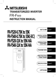
1
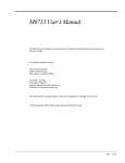
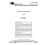
$6& 2SHUDWLRQ0DQXDO $[LV$GYDQFHG6HUYR&RQWUROOHU Copyright 1998 Positive Logic Engineering. All rights reserved Version 1.0 Positive Logic Engineering P.O Box 6521 Santa Rosa, CA 95406-0521 www.positivelogic.net [email protected] 1. Introduction The ASC16 is a servo motion controller that controls R/C type servo motors from a host computers serial port. The ASC16 alleviates the task of precision-profiled motion control and motion synchronizing from your host computer−whether that be a PC, a single board computer, or a microcontroller. Think of it as a motion coprocessor for your system. The ASC16 can receive a long list of tasks downloaded to it by the host computer, perform those tasks independently from the host, and report information to the host as needed. The ASC16 contains many of the advanced features found in industrial motion controllers. 1.1. • • • • • • • • • • • • • • • • • • • 1.2. Key Features 4000-count position resolution yields .045-degree resolution for typical 180° Servos 256- count speed resolution 256-count acceleration resolution Input cache can hold up to 128 bytes of commands and data Software-selectable-position coordinate polarity allows user to logically invert the direction of servo Event triggering commands cause special actions controlled by internal events. An event trigger could be one of the following • Servo position flyby • Servo motion completion • Time delay The special actions taken based on condition of the triggered events are one, or both, of the following: • Report to host when condition of trigger is satisfied • Suspend command processing until condition of trigger is satisfied Up to 256 ASC16 modules can be individually enabled Motion freezing and aborting Servo on/off control Read/Write Digital I/O ports Read 8-channel Analog port Saving and loading position, speed, acceleration and coordinate polarity defaults to nonvolatile EEPROM memory. Power-up reset will autoload defaults Uses RS-232(TTL) serial communications to receive commands and transmit reports Code markers to report command execution position or multipurpose identification Query actual position or speed for verification or to aid in synchronizing a multitask scheme A Windows-based motion scripting and download tool with visual interface 34 commands Transmitted commands are numeric (binary) codes and not mnemonic (ASCII) codes, which increases command throughput Built-in switching regulator and board layout features can handle multiple power source solutions Getting Started A good first step is to test the ASC16 using the auto-test feature This test will determine if the board is operating properly. To test the serial communications function the auto-test function sends out data periodically from its serial port. Sending the ASC16 a Terminate instruction will determine if the ASC16 is receiving properly too. For this test it would be a good idea to connect the ASC16 to a PC serial port so that it can talk to the ASC16 via the SCEdit program. Even if you plan to use another controller as a host, the initial connection to a PC is the easiest. Later it will also be useful to use with the SCEdit program in facilitating a fast and effective way to test motion script segments. ASC16 Users Manual 3 Here are the steps it takes to get an ASC16 up and running on a PC for the first time. 1. If purchased as a kit, build the ASC16 circuit according to the assembly instruction in Section 4. 2. A level converter is needed to translate standard RS-232 level to TTL level for the ASC16. If you need a level converter, build the one described in Section 3.5, or buy one from Positive Logic Engineering. 3. Connect your RS-232 level converter between your PC and the ASC16 serial port, P18. 4. Install the SCEdit program if you haven’t already. 5. Launch the SCEdit program; select your serial port from the Settings Menu. 6. Connect a servo to servo port1 (connector P1). Make sure the pin-out of your servo matches the requirements of the ASC16. Signal on pin 1, +Voltage on pin 2, and ground on pin 3, which is closest to the edge of the board. Consult the hardware section for more information. 7. Place a jumper across the two pins of JP1 on the ASC16. 8. Connect a power source of choice to TB1. A four-cell alkaline or NiCd pack is a good choice for starters. See hardware section for tips about power sources. 9. At this point you should notice your servo moving from one position limit to the other. You should also observe data coming into the input window of the SCEdit program. These actions verify ASC16 operation and serial transmission. 10. By pressing the Terminate button, the SCEdit program sends out the Terminate command. The servo should stop moving and the received data should stop coming. This verifies that the ASC16 is receiving data. This completes the initial test of the ASC16. Don’t forget to remove the jumper across JP1. For going further, see the next section and the “Using SCEdit” Section 6. 1.3. Operation 1.3.1. Sending commands to the ASC16 Commands, and data, are received by the ASC16 from a host computer via an RS-232 (TTL) serial port at connector P18. The RS-232 parameters are 9600 baud 8 data bits, 1 stop bit, and no parity. A level converter which can translate the TTL level signals to true RS-232C voltages is available from Positive Logic Engineering at www.positivelogic.net, or see Section 3.5 of this manual for plans to build this converter yourself. For more details about the ASC16s serial port see Section 3.5. 1.3.2. Processing commands At a baud rate of 9600, commands will transfer to the ASC16 from the host at a rate of about 1mS per byte. The longest commands would then take 3mS to send to the ASC16. All received commands, and data, are placed in a FIFO cache, know as the command cache. The ASC16 can process commands much faster than the serial transfer rate, so unprocessed commands don’t last long in the cache. There are, however, some commands that tell the ASC16 to suspend processing commands until certain conditions are met. In this case, commands and data subsequently received will start stacking up in the command cache. The command cache can hold up to 128 bytes of commands and data. When the conditions of the command that disabled the processing of commands are satisfied, the ASC16 will proceed processing commands in the command cache. Commands that suspend the processing of commands are called trigger commands. Trigger commands are event driven triggers. See the Command Set Section for more details and ideas on how to use these commands. 4 ASC16 Users Manual 2. COMMAND SET The ASC16 has 34 different commands. There are 1-2-and 3-byte commands. The 2nd and 3rd bytes in a multiple byte command string are data bytes. There are two methods for inserting servo number information into the command strings addressing particular servos. One method is to offset the command number with the servo number. Take the Move command, for example. There are 16 possible command values for this command, one for each servo number. Using the offset method, numbers 1 through 16 are the Move commands for servo numbers 1 through 16. This method of addressing is applied to the more frequently used commands, and helps increase their throughput. Including the servo number in the 2nd byte of the command string is the other method for inserting servo number information into the command strings. This method is applied to less frequently used commands. The ASCII version of the command, which requires a servo number, is denoted in the following descriptions with a ‘$’ character. A number between 1 and 16 is substituted with the ‘$’ character Position-value commands are the only 3-byte commands in the command set. These position values require a 2 bytes due to the high 4000-count resolution. The most significant bye (MSB) is sent first, followed by the least significant byte (LSB). Two-byte command data are denoted in the following descriptions with a ‘##’ (two pound characters). Commands with a single byte are denoted with a ‘#’ (single pound character). Commands which contain a position value are the only 3 byte commands in the command set. These position values require 2 bytes due to the high 4000 count resolution. The two bytes need to be sent with the MSB (most significant byte) sent first, followed by the LSB (Least significant byte). Two-byte command data are denoted in the following descriptions ‘##’ (two pound characters). Commands that have a single byte operand are denoted with a ‘#’ (single pound character). Most of the following descriptions show an example of how the command is used in a motion script. In these examples the mnemonic equivalent of the command is shown in the left hand column, and the equivalent binary or numerical values are shown in the right-handed column. The mnemonic commands can be typed directly into the SCEdit program, and the numeric commands can be put into microcontroller data tables. ac (81-96 DEC) (51-60 HEX) Acceleration Format: ac$ accel ac$ = 81-96 for servo 1 (ac1) to 16 (ac16) accel = 1-255 Description: This command sets the acceleration rate for a servo. The acceleration rate units are ¼ count/20mS2 or 625 counts/Sec2 or 1/13 Revolutions/sec2. That is, that for every unit of acceleration, a servo will increase its speed 625 counts/second every second. I have observed standard servos accelerating at a rate equivalent to an acceleration setting of about 100. Highspeed servos accelerate at faster rates. The ASC16 does not know the maximum acceleration of a servo. If you set servo’s acceleration higher than its capabilities, the ASC16 will calculate inaccurate servo positions, and cause flyby event triggers to be miscalculated. ASC16 Users Manual 5 A good application for acceleration control is to lessen the forces created by an accelerating robot arm. Newton’s Law states that force = mass * acceleration. Abrupt changes in speed (high acceleration) causes a robot arm (mass) to generate forces, which can cause the arm to overshoot; Those forces are also applied to the gears of the servo. Consider that a standard servo can accelerate at a rate of up to 65000 counts/sec 2 or about 8revolutions/sec2. The end of a 6-inch arm would then accelerate at a rate of 24feet/sec2. If one G force is 32feet/sec2, then 24ft/s2 is +/-3/4 G. This means that any weight at the end of that arm, and proportionally any weight on the arm (proportional to distance from center of the arm to the end of the arm), is almost going to double during acceleration and/or deceleration. Example mnemonic tl 2 ac1 5 fp1 1000 mv1 3000 tp1 ac1 3 am ‘ set trigger level to suspend processing ‘set acceleration rate for servo 1 to 5cnts/20mS2 ‘set flyby position for servo 1 at 1000 ‘move servo to new position ‘wait here until servo has gotten up to speed ‘change acceleration (for deceleration) to 3 (250 DEC) Numeric 119, 2 81, 0, 5 21, 3, 232 1, 11, 184 201 81, 0, 3 (FA HEX) Abort All Motion Format: am am = 250 Description: Aborts motion of all servos. The servos will decelerate at the servos full deceleration ability rather than via tha ASC16’s control. Example mnemonic am rp1 rp2 rp16 6 ‘stop all servo where they stand ‘now tell host at what position they stopped at Numeric 250 116, 1 116, 2 116, 16 ASC16 Users Manual at (249 DEC) (F9 HEX) Abort Triggers Format: at at = 249 Description: Abort all pending event triggers. Only works when the trigger level is set to 1, because if higher-level triggers (2,3) are used, this command won’t be seen until after they, (2,3) have been satisfied. For this reason this command is not usually embedding in the command string, rather it is sent by the host as needed, in a control scheme were level 1 triggers are used. Example mnemonic tl 1 mv 1 100 mv 2 200 tm1 tm2 ‘set trigger level to report only ‘move some servos ‘send message when these moves are done Numeric 119, 1 1, 0, 100 2, 0, 200 181, 182 Until the host sees both 181 and 182 from the ASC16 (signifying that the motion of those two moves is complete) it periodically sends the following command. rd ‘read sensors connected to input port 179 Until the host decodes the returned data to find that your robot just crashed into something, it issues the following command: am at bt ‘abort all motion 250 ‘abort triggers, since the host now knows that motion 249 is complete. (124 DEC) (7C HEX) Base Time Format: bt # bt = 124 # = 0 to 255 for 0 to 1020uS (4uS steps) Description: This sets the minimum pulse width output of the servo command signal. The operand value is the pulse width value divided by 4microseconds. Many servos like to operate between the range of .7mS and 1.7mS. A value of 175, which yields 700uS, or .7mS (4uS * 175) would be the appropriate value to set for most servos, and is the factory default. Some servos operate from as low as 250uS (.25mS) to 2.25mS. For these it is be advantageous to set the base time to 63 (63*4uS = 252uS) to get full range of motion from the servo. This base time flexibility allows your servos to have full range of motion even if they do not conform to a standard; otherwise, as in the example above, you would lose 25% of the servo’s range of motion if you didn’t change the base time value. The base time value is always stored in non-volatile memory. As with all commands that save data to non-volatile memory, it is a good idea to turn off the servos (s-) while the data is being “burned” into EEPROM. This process uses a little over 20ms per byte of the controller’s undivided attention, and during this process updates to the servos are missed. Erratic behavior may result. Examples mnemonic bt 175 ‘Yields a range of .7mS for position 0 to 1.7mS for position 4000 bt 63 ‘Yields a range of .25mS for position 0 to 1.25mS for position 4000 ASC16 Users Manual Numeric 124, 175 124, 63 7 en (121 DEC) (79 HEX) Enable Module Format: en address en = 121 address = 0 to 255 Description: Enables a module for receiving commands. Only one module address is enabled at a time, but multiple modules can share the same address. Any module that is not enabled will ignore all commands sent, except for an enable module command for that modules address or the Terminate command. A multi-drop RS-485 serial network or a unidirectional (only the host can transmit) RS-232 can be setup to control multiple ASC16 controllers (modules). All commands sent by the host in a network are received by all modules and use up command cache space on every module. Only the enabled module will process the commands. Example The use of Markers (see mk commands) can be used in conjunction with trigger reporting to identify which module is reporting information. See example below mnemonic Numeric en 1 ‘enable module 1 121, 1 tl 1 ‘set trigger level to report mode only 119, 1 mv7 3000 ‘move servo 7 on module 1 7, 11, 184 tm7 ‘when motion on servo 7 is complete, report back 187 mk1 ‘then send a marker so that it identifies module 1 221 en 2 ‘now enable module 2 and send more commands 121, 2 tl 1 ‘set trigger level to report mode only 119, 1 ……………more commands for module 2 here ………………… tm9 ‘report when servo#9 is finished moving 189 mk2 ‘to identify module 2 222 When Module 1, servo 7, has completed its move, the host will receive the following 2 bytes: 187 meaning that trigger for servo 7 is satisfied 221 caused by Marker#1, which we used here to identify module 1. f+ (251 DEC) (FB HEX) Freeze Motion Format: f+ f+ = 251 Description: Freeze the motion of all servos. The motions may resume their destination paths upon the receipt of the Freeze On command (f-). The servos will decelerate at their full deceleration ability rather than via the ASC16’s control. Example mnemonic mv 1 100 ‘move some servos mv 2 200 The host then sends the following command: f‘freeze Mister! When the host wants to resume motion, it sends this: f+ ‘carry on 8 Numeric 1, 0, 100 2, 0, 200 251 252 ASC16 Users Manual f- (252 DEC) (FC HEX) Freeze Motion Off Format: f- f- = 252 Description: Resume the motion of all servos previously held by a Freeze Motion On command “F-“. The servos will accelerate at their full acceleration ability rather than via the ASC16’s control. Example See Freeze Motion On command above fp (21-36 DEC) (15-24 HEX) Flyby Position Format: fp$ position fp$ = 21-36 for servo 1 (fp1) to 16(fp16); position = 0-4000 Description: This command will store a fly-by position trigger in memory for any given servo. Once a fly-by position has been put into memory for a servo, a Trigger-On-Position (tp#) command can be used to trigger a message, to suspend the processing of commands in the command cache, or do both−depending on the current trigger level (tl). A “tp” command is satisfied when the specified servo passes through the position pointed by the fly-by position value or the motion of said servo is complete. Example: Mnemonic tl2 fp1 1000 fp9 3333 mv1 0 tp1 op128 tl1 mv9 3500 tp9 ‘ set trigger level to suspend processing ‘ set trigger positions for servos 1 and 9 ‘ set trigger positions for servos 1 and 9 ‘ move servo 1 to position 0 ‘because tl=1, suspend processing until fp1 1000 ‘ set bit 8 on output port ‘ set level to report trigger only ‘ set servo 9 into motion ‘arm trigger Numeric 119, 2 21, 3, 232 29, 13, 5 1, 0, 0 201 110, 128 119, 1 9, 13, 172 209 Commands will continue to process, and at the point when servo 9 passes position 3333, the number 29 (synonymous with the code 29 for fp9) will be sent by the ASC16. iv (112 DEC) (70 HEX) Invert Servo Coordinates Format: iv servo iv = 112 servo = 1 to 16 Description: This command sets a servo into inverted coordinate mode. This inverts the position values of any servo. The assigned servo remains in this mode until changed back using the ‘nv’(non-invert coordinates) command, or the ASC16 is reset and the default mode for the servo is non-inverted. If, before issuing this command, position 0 is the counter-clockwise limit and position 4000 is the clockwise limit, after this command, position 4000 will be the counterclockwise limit and position 0 will be the clockwise limit. This command causes no movement to ASC16 Users Manual 9 occur To move a servo to its new position on its new coordinate polarity without changing the position value, do a move relative 0 for the newly set servo; i.e., “mr1 0” for servo 1. This command makes it simple to change the positive direction of a servo. For instance, you can set one of two servos inverted if you have two servos facing opposite one another, making them track in the same direction for similar position values. The current inverted/non-inverted coordinate status of all servos can be saved into the non-volatile default registers for automatic reassignment at power-up by using the Save All (sa) command. Example mnemonic Numeric mv1 100 ‘move servo 1 to position 100 1, 0, 100 iv1 ‘invert servo 1 position. At this point, the servo is still going to position 100 in noninverted coordinates. 112, 1 mr1 0 ‘regardless of where servo 1 was going or where it was, it is now going to position 100 (absolute) in inverted coordinates. 41, 0, 0 la (242 DEC) (F2 HEX) Load All Format: la la = 242 Description: Restores all default speeds, acceleration, coordinate polarities, and moves all servos to their default positions which were stored in the default registers in non-volatile memory. The servos will move at the newly loaded default speeds and accelerations assigned to each individual servo. Example mnemonic Numeric tl 2 ‘set trigger level to suspend processing of commands 119, 2 la ‘restore all defaults and move to the default pos. 242 tm1 tm2 tm3 tm4 ‘wait for all motion to complete 181, 182, 183, 184 tm5 tm6 tm7 tm8 185, 186, 187, 188 tm9 tm10 tm11 tm12 189, 190, 191, 192 tm13 tm14 tm15 193, 194, 195, tl3 ‘ change trigger level to include a report for the last 119, 3 tm16 ‘so now the host will know when all motion is complete 196 ld (123 DEC) (7B HEX) Load Default Position Format: ld servo ld = 123 servo = 1 to 16 Description: Moves a servo to its default position which is stored in the default position registers in non-volatile memory. The servo will move at the speed and acceleration currently assigned to that servo. Example mnemonic ld 11 10 ‘move servo to its default position Numeric 123, 11 ASC16 Users Manual lm (253 DEC) (FD HEX) Loop Marker Format: lm lm = 253 Description: Used as a place-mark in the command cache of where execution of commands should begin after receipt of a Loop command (lp). Example See Loop command below lp (254 DEC) (FE HEX) Loop Format: lp lp = 254 Description: Causes the ASC16 to re-execute commands in the command cache at the location where the last Loop Marker was placed. Once a command loop has started the only exit is the receipt of the Terminate command (no, no, no : 0,0,0), after which execution of commands will begin at the very next command following the Loop command. Example Here is a section of code that makes my 4-legged robot walk. mnemonic Numeric fp9 3100 ‘set trigger on leg four position 29, 12, 28 tl 2 ‘set trigger level to suspend processing of commands 119, 2 lm ‘ set a loop mark for looping ‘ leg 1 movements tp9 ‘wait here for other leg to be in phase b location sp1 100 sp2 100 ‘forward step speed mv2 4000 ‘now have leg take a step mv1 1200 ‘lift foot a little, too tp1 ‘wait till leg is forward mv2 3100 ‘move foot down sp1 4 ‘restore walking speed (slow) mv1 0 ‘walk ‘ other 3 legs move here lp ‘ loop back to loop marker ASC16 Users Manual 253 209 61, 100, 62, 200 2, 15, 160 2, 4, 76 201 2, 12, 28 61, 4 1, 0, 0 254 11 mk (221-228 DEC) (DD-E4 HEX) Marker Format: mk# mk# = 221 to 228 for marker numbers 1(mk1) through 8(mk8) Description: The purpose of the marker command is to provide a means for sending an identifiable tag back to the host. The value sent back to the host is identical to the marker code number. This marker can be used to signify the progress of commands in the command buffer cache, or specific marker number combinations can be used to identify one ASC16 module from another in a shared serial-communications configuration. Example If it is desired to send a block of commands larger than the command cache, the block can be divided up into smaller blocks. Toward the end of these blocks a marker is inserted so that the host can tell when the ASC16 is almost finished with that block of commands. Now the host can send another block. By placing the marker near the end and not at the end of a block, the ASC16 (and the servos for that matter) will see no interruptions and it will process the remaining commands as new ones are loaded in behind them. mnemonic Numeric Block of commands sent here mk1 ‘marker used as a end of block marker 221 A few more commands here The host now waits for the ASC16 to return the marker before feeding another chunk of code. mr (41-56 DEC) (29-38 HEX) Move Relative Format: mr$ position mr$ = 41-56 for servo 1 (mr1) to 16 (mr16) position = -4000 to +4000 Description: The ASC16 moves a servo to a new position at the speed and acceleration rate set for the specified servo relative to the current position. If the new absolute position is calculated to be less than 0 or greater than 4000 counts, the servo will move to the nearest position limit (0 or 4000 absolute). Example: mnemonic tl 2 mv5 800 tm5 mr5 1000 tm5 mr5 -800 tm5 rp5 12 ‘ set trigger level to suspend processing ‘ move servo 5 to absolute position 800 ‘wait for servo to finish move ‘move servo 5 relative +1000 counts (1800 absolute) ‘wait for servo to finish move ‘move servo 5 relative -800 count (1000 absolute) ‘wait for servo 5, then report position (absolute) Numeric 119, 2 5, 3, 32 185 45, 3, 232 185 45, 252, 224 185, 116, 5 ASC16 Users Manual mv (1-16 DEC) (01-0F HEX) Move servo absolute Format: mv$ position mv$ = 1-16 for servo 1(mv1) to 16 (mv16) position = 0-4000 Description: Moves a servo to a new absolute position at the speed and acceleration rate set for the specified servo. Example: Mnemonic mv2 1500 mv10 200 no Move servo 2 to position 1500 Move servo 10 to position 200 Numeric 2, 5, 220 10, 0, 200 (0 DEC) (00 HEX) No Operation Format: no no = 0 Description: The ASC16 will do nothing when this command is processed. Be careful not to use three of these in a row or you will create a terminate command. This could also happen inadvertently if you follow a ‘no’ command with a move command to position 0; i.e., mv1 0 ‘move servo 1 to position 0 no ‘no op. The equivalent numeric values would be 1,0,0,0. The ASC16 will interpret any three zeroes in sequence as a terminate command. no no no (0,0,0 DEC) (00,00,00 HEX) Terminate Format: no no no no no no = 0, 0, 0 Description: This command goes into effect immediately upon receipt of the third 0, essentially "taking cuts" in front of all the other commands in the cache. The ASC16 executes the Terminate command, exits a loop if a loop is active, and begins executing commands following the Terminate command. This command is really three no operation commands (‘no’) in a row. See the ‘no’ command for information about inadvertently creating a terminate command sequence. nv (113 DEC) (71 HEX) Non-invert Servo Positions Format: nv servo nv = 113 servo = 1 to 16 Description: This command sets a servo into the non-inverted coordinates. See command ‘iv’ for more details. ASC16 Users Manual 13 op (110 DEC) (6E HEX) Output Format: op value op=110 value = an 8bit value (0 - 255) Description: Sends a value to the output port. Whip out your calculator or handy-dandy decimalto-binary conversion chart to determine what value(s) you’ll need to send the ASC16 to set the appropriate bits on the output port. Example mnemonic tl 2 op 0 mv1 1200 tm1 op 128 pg ‘ set trigger level to suspend processing ‘clear the output port ‘send a servo to a position ‘wait until servo is finished moving , then ‘set bit 8 (120 DEC) Numeric 119, 2 110, 0 1, 4, 176 181 110, 128 (78 HEX) Program Module address Format: pg address pg = 120 address = 0 to 255 Description: Stores in non-volatile memory a new module address if program jumper JP1 installed. Any ASC16 module listening (connected to the host serial port)−regardless of current module address−will be programmed to a new module address. This means both networked and single-node modules. The ASC16 is module addressable by using the Enable command. See the Enable command ‘en’ for more details. Multiple ASC16s can be connected by using an RS-485 network, or in an unidirectional (only the host can transmit) RS-232. Each module can be programmed by using this command to a unique address. Install the JP1 jumper to each module one at a time, and send the Program command. The ASC16 factory default address is 255. Do not leave JP1 installed. If you do, at the next power-up the auto-test sequence will start. Example mnemonic pg 1 en 1 14 ‘the module with JP1 install gets a new address ‘now only talk to newly programmed module Numeric 120, 1 121, 1 ASC16 Users Manual ra (141-148 DEC) (8D-94 HEX) Read Input as Analog Format: ra# ra# = 141 to 148 for analog input 1(ra1) through 8(ra8) Description: Sends a value back to the host proportional to the voltage applied to one of the analog input channels. This analog value is preceded with a value equal to the command number (i.e. 141-148). Example mnemonic ra5 rd ‘read the analog value on input 5, and send to host (179 DEC) Numeric 145 (63 HEX) Read Inputs as digital Format: rd rd = 179 Description: Reads the entire input port as a digital byte and sends value to controller. This digital value is preceded with an identification code value equal to the command number (179). Example mnemonic rd rp ‘Read input port as digital byte (116 DEC) Numeric 179 (74 HEX) Report Position Format: rp servo rp = 116 servo = 1 to 16 Description: Sends the present servo position, moving or not, to the host via the serial port. Unlike the reporting features of trigger commands, here the ASC16 will not send an identifying code byte, it will send only the position information (in two bytes). For this reason, the host controller must be ready to receive the position data. The idea is to make the transmission of position information as quick as possible, for external position following. Example mnemonic Numeric tl 2 ‘set trigger level to suspend processing of commands 119, 2 mv16 0 ‘move servo16 to position 0 16,0 ,0 lm ‘set looping marker 253 tt 10 ‘wait 100 mS 111, 10 rp16 ‘send servo 16 actual position ever 100mS 116, 16 lp ‘continuously loop back to loop marker 254 It’s up to the external controller, which is reading the position feedback, to send a termination string which will exit the loop. ASC16 Users Manual 15 rs (117 DEC) (75 HEX) Report Speed Format: rs servo rs = 117 servo = 1 to 16 Description: Sends the present servo speed. See the Report Position command, which works quite the same. s+ (245 DEC) (F5 HEX) Servos On Format: sa sa = 245 Description: Enables the control of all servos’. All servo positions will now move to their last programmed positions at the servos full speed and acceleration capabilities. Example mnemonic en 255 s+ s- ‘enables default modules and turn’ on all servos (246 DEC) Numeric 121, 255, 245 (F6 HEX) Servos Off Format: s- s- = 246 Description: Disables the control of all servos. All servos will act like they’re shut off. Example mnemonic ssa s+ sa ‘turn off servos ‘save all defaults ‘turn servo back on (241 DEC) Numeric 246 241 246 (F1 HEX) Save All Format: sa sa = 241 Description: Saves all current positions, speeds, acceleration, and coordinate polarities to the default registers in non-volatile memory. As with all commands that save data to non-volatile memory, it is a good idea to turn off the servos while the data is being “burned” into EEPROM. This process uses a little over 600ms of the controller’s undivided attention, and during this process updates to the servos are missed, causing the servos to act erratic. Example See the Save command “sv”. 16 ASC16 Users Manual sp (61-76 DEC) (3D-4C HEX) Speed Format: sp$ speed sp$ = 61-76 for servos 1(sp1) to 16 (sp16) speed = 0-255 for speeds of 0 to 255counts/20mS Description: This sets the speed of a servo. The rate of speed is in counts/20mS. So each unit of speed equals 50 counts/second. For a servo that turns 180 degrees for positions 0 to 4000 (8000 counts/ rev), each speed unit count will equal =50counts/sec = 1/160 of a revolution/sec or =2.25 degrees/second or =3/8(.375)RPM. Using the above to control a servo at 3 RPM, the speed value would be: 3/.375 = 8. Let’s say you want to move a joint of a robot arm, which is directly controlled by a servo, at a maximum rate of 30 degrees per second. The speed value to send the ASC16 would be 13 (30/2.25)−rounded off. Scale these values depending on the arc range of your particular servo. At 4.8Volts the most common maximum servo speed is .22sec/60 Degrees or 1.32S/rev or 45 RPM. Of course, as the voltage is increased, the maximum speed increases; likewise, if the voltage decreases, the maximum speed will decrease. Higher load torque will also decrease the maximum speed when it is near the high end of the torque rating for the servo. As long as the speed setting in the ASC16 is lower than the maximum obtainable speed for the voltage and torque being applied, the speed will be accurate. For the .22S/60 Degree servo (at 4.8V) a speed value of 120 (45/.375) will be the highest practical value for that servo. Knowing the transit time for a 60 Degree move (which is a common specification supplied by servo manufacturers), to determine the maximum speed for a given servo use the following formula. This applies only to 180-arc-degree servos. 26.4 / transit time = maximum speed value (counts/20mS) The ASC16 does not know the maximum speed of a servo if you set the speed of a servo higher than its capabilities, the ASC16 will calculate inaccurate servo positions and cause any event trigger to be miscalculated. Example: mnemonic tl 2 fp3 1000 sp3 50 mv3 3890 tp3 sp 100 ASC16 Users Manual ‘set trigger level to hold execution ‘set flyby position to 1000 for servo 3 ‘set initial speed for servo 3 at 133 RPM ‘ move servo 3 to position 3890, at speed 50 ‘wait for servo3 to pass position 1000 ‘ then double its speed Numeric 119 2 23 3 232 63 50 3 15 50 203 63 100 17 st (151- 168 DEC) (97 - A8 HEX) Stop Format: st$ st$ = 151 to 168 for servo 1 (st1) to servo 16 (st16) Description: This command causes the specified servo to stop moving. If a flyby position or motion event trigger command is pending, it will be terminated. Neither event trigger will not report completion to the host even if trigger level (tl) was set to 1. This command is only practical for use with flyby position or motion event trigger commands if the trigger level (tl) is set to 0 or 1. At higher levels this command will not be processed until the event trigger is satisfied. Use the Report Position command, rp, to find the position where the servo stopped moving. Example: The example below illustrates one way to stop leg movement of a legged robot. Sensors are placed on the bottom of each foot. The sensors output a voltage proportional to the amount of pressure applied to them when pressed against the ground. Two of these sensors are connected to the ASC16’s analog port channels 3 and 4. This idea also works with gripper sensors on an armed robot. mnemonic Numeric tl2 ‘trigger level set to hold processing only 119, 2 mv1 3440 ‘move servo 1 1, 13, 112 The host can repeatedly send the following command to read the system’s touch sensor: ra 3 ra 4 ‘read analog input#3 - touch sensor input 143, 144 Once a value representing the proper pressure is registered, the host then sends the following: st1 ‘stop servo 1 151 rp1 ‘tell host where it stopped 116, 1, Or for leg number two: st2 ‘stop servo 1 152 rp2 ‘tell host where it stopped 116, 2 sv (122 DEC) (7A HEX) Save Default Servo Position Format: sv servo sv = 122 servo = 1 to 16 Description: Saves the current servo position to a default position register in non-volatile memory. The next time the ASC16 is turned on, the positions stored in the default position registers will be the initial servo positions. Also see the command Save All (sa). As with all commands that save data to non-volatile memory it is a good idea to turn off the servos while the data is being “burned” into EEPROM. This process takes more than 60ms of the controller’s undivided attention;, during this process updates to the servos are missed. Erratic behavior is common. Example mnemonic Numeric tl 2 ‘set trigger level to suspend processing of commands 119, 2 tm 2 ‘wait for servo 2 to stop moving 182 s‘turn off servo to eliminate convulsions 246 sv 2 ‘save to current 122, 2 mk 1 ‘ use a marker to signify to host that save is completed 221 s+ ‘turn servo back on. 245 The servos should have been off for only about 25mS in this example. 18 ASC16 Users Manual tl (119 DEC) (77 HEX) Trigger Level Format: tl level tl = 119 level = 1, 2, or 3 Description: Sets the event trigger level. Once the level is set, all following trigger commands will be affected until another level is set. If a trigger command is in process (not yet satisfied) and a new trigger level is issued, the trigger command will take on the behavior of the new level. The trigger levels are as follows: 0 - Event Trigger commands are ignored 1 - Report: Send confirmation via serial port message that a trigger is satisfied. 2 - Wait: Suspend command processing until present trigger condition is satisfied. 3 - Both: Suspend until present trigger is satisfied, and send confirmation Example mnemonic mv1 0 ‘move servo 1 to position 0 tl2 ‘set event trigger level to hold command processing tm1 ‘wait here until servo 1 is done moving tl 0 ‘ASC16 will not process trigger command at all mv1 2000 ‘more move commands without reporting or waiting tm Numeric 1, 0, 0, 119, 1 181 119, 0 1, 7,208 (181-196 DEC) (65-C4 HEX) Trigger on Motion Completion Format: tm$ tm$ = 181 to 196 for servo numbers 1 (tm1) to 16 (tm16). Description: Depending on the current trigger level, this command either causes the ASC16 to wait until a specified servo’s current move has ended, or sends a message to the host via the serial port when the specified servo’s current move has ended, or both (wait and send a message). When the ASC16 waits, no other commands in the command cache are processed until the trigger is satisfied. The trigger in this case is the completion of a servo move. In trigger levels 1 and 3 the message that is sent when the trigger is satisfied is the value 181 through 196 for servo numbers 1 through 16, which is the same as the code for ‘tm#’ Example mnemonic tl 2 mv1 100 tm2 mv1 1000 tp ‘set trigger level to suspend processing of commands ‘move servo 1 to position 100 ‘wait for move to complete ‘now move same servo to position 1000 Numeric 119, 2 1, 0, 100 181 1, 3, 232 (201-216 DEC) (C9-D8 HEX) Trigger on Servo Position Format: tp$ tp$ = 201 to 216 for servos 1 (tp1) to 16 (tp16) Description: Depending on trigger level, this command either causes the ASC16 to wait until the specified servo passes through the preprogrammed fly-by position, or sends a message to the host via the serial port when the event has occurred, or both (wait and send a message). When the ASC16 Users Manual 19 ASC16 waits, no other commands in the command cache are processed until the trigger is satisfied. The trigger in this case is the passing (fly-by) of a servo position. The trigger will also be satisfied when the servo has finished its move, regardless if it passed the fly-by position or not. In trigger levels 1 and 3 the message that is sent when the trigger is satisfied is the value 210 through 216 for servo numbers 1 through 16, which is the same as the code for ‘tp# Example See the example for fly-by position “fp” tt (111 DEC) (6F HEX) Trigger on Time Delay Format: tt time tt=111 time = 0 - 255 for delay of 0 to 2550mS (2.50 Seconds) Description: Depending on the current trigger level, this command either causes the ASC16 to wait a specified amount of time, or sends a message to the host via the serial port, when a time delay has finished, or both (wait and send a message). When the ASC16 waits, no other commands in the command cache are processed until the time delay if finished. In trigger levels 1 and 3 the message that gets sent when the time delay is finished is the value 111, which is the same as the command code for ‘tt’. This function uses the servo update loop as its time base, so for this reason the servos must be ON, via the ‘s+’ command, for the ‘tt’ command to work properly. Example mnemonic tl 1 mv14 1000 tt 10 mv15 1000 wf Numeric ‘send message when trigger is satisfied119, 1 ‘move servo 14 to position 1000 14, 3, 232 ‘wait 100mS, then send a message 111, 10 ‘thus servos 14 and 15 will appear to move simultaneously 15, 3, 232 (243 DEC) (F3 HEX) Wait forever Format: wf wf = 243 Description: Causes the ASC16 to discontinue executing commands until a terminate command is received by the ASC16. Example mnemonic wf Numeric ‘Now the ASC16 will indefinitely halt execution ‘of commands in the command cache. mv1 100 mv2 200 ‘move a bunch of servos 243 more commands here (possibly to multiple ASC16 modules) no no no 20 ‘Immediately upon receipt of this terminate command, execution of commands will begin again (for all modules) starting move commands above 0, 0, 0 ASC16 Users Manual 3. HARDWARE Figure 2 3.1. Servo Ports The servo port connectors P1 through P16 are wired for Futaba-compatible servo connectors. You can rearrange the pins in the connector shell of other servo types to match that of the Futaba type. Pin 1 2 3 3.2. P1 through P16 Pin-out Description Typical wire color on servo Signal White or Yellow V+ Red Ground Black POWER CIRCUITRY The ASC16 contains a DC-DC converter circuit for optimum power source conditioning. It has high immunity to power sags caused by servo motor high inrush currents. This conditioner can be adapted to just about any power source condition. As long as the voltage into the converter (at TB1) is between 2 and 6 Volts, the controller will operate properly with the default configuration. Surplus 5V power (about 150mA worth) is available to power another controller. These features enable the use of 1 Battery pack to power an entire system. Here are a few ideas regarding power sources. 3.2.1. NiCd Batteries. Use 4 or 5 cells with the default circuitry. For a 6 Cell (7.2Volt) battery pack, replace the jumper wire on U6 with two diodes in series to drop the voltage below 6 Volts. Most servos operate at 4.8V-6.0V, operating at higher voltages may damage a servo. ASC16 Users Manual 21 NiCd batteries have a lower internal resistance, making them ideal for motor/servo applications. The servos can have tighter (stiffer) responses and be less susceptible to torque disturbances. Again, if you wish a more damped (less sharp) response while using NiCds, simply decrease the acceleration setting in the ASC16. The .1 Ohms resistance is one example figure 3 3.2.2. Alkaline Batteries. Use 4 Cells with default ASC16 configuration. And for heaven’s sake, use the rechargeable type Renewal, or the cost of replacing them will eat you alive. Alkaline batteries have a higher internal resistance than NiCds and may exhibit a more damped response. The inrush current that servos create will cause the voltage to sag more with the higher source resistance of the alkaline. This will happen more likely with the increase of the number of servos driven. I like using alkaline for those applications that don’t need higher torque, and for snappy moves because thier recharging regiment is a lot less fuss than NiCd and I get good performance and value. 3.2.3. >7.2 Volt power source. If your system uses a higher voltage than 7.2V, simply install a three-terminal 5Volt regulator into the U6 position. Be careful, the servos will get whatever voltage you apply at TB1. Extra through-hole pads have been provided near U6 and TB1 to accommodate wires for special power wiring requirements. If you plan to exceed 10 Volts at TB1, remove or replace R8 with a higher value to keep the voltage into the A/D converter from exceeding 5Volts (see voltage monitor input, Section 1.1.3). 3.2.4. Surplus 5Volt power. The ASC16 circuitry only draws about 100mA. This is less than half of the 250mA the DC-DC converter can deliver. By using the surplus 5volt power to power an external controller, your controller will have a clean 5V source and your system can be reduced to one battery pack. This 5Volts is on connector P20. 3.2.5. Voltage monitor input. The 8th input bit has a 2:1 voltage divider attached to facilitate the measurement of battery voltage. Two 4.7Kohm resistors form this divider, connected from V+ (power source at TB1) to ground. The VRL and VRH signals have to be connected for this to operate properly. See Section 1.1 for more information. By issuing the following command: ra8 (148 Decimal) The ASC16 controller will return a value proportional to battery voltage. The scaling of this value is such: Voltage at V+ = value/255 * 10 (or A/D value/25.5 or 39.2mV*bit) where “value” is the second number returned from an RA8 command. The first number is the ID code, which is eqaul to the command number, i.e. 148 for ra8. 22 ASC16 Users Manual 3.3. OUTPUTS The ASC16 output port includes an 8-bit high current sinking output driver. A Darlington transistor array ULN2803 - can deliver up to ½ Amp per output, and has built-in flyback diodes for protect against inductive loads. I would suggest an external high-speed diode to supplement this internal diode. Something like a 1N4937 will do nicely. The outputs are open collectors and are intended to operate such that if a binary value 1 is sent to the output port the transistor will sink its load to ground. figure 4 A pull-up resistor is required to make this output logic compatible to interface to other digital devices. Note that +5V is not available on P21. Use P20 figure 5 ASC16 Users Manual 23 Pin 1 2 3 4 5 3.4. Output Port P21 Pin-out Description Pin Description Output 1 6 Output 6 Output 2 7 Output 7 Output 3 8 Output 8 Output 4 9 V+ (Battery) Output 5 10 V+ (Battery) INPUTS 3.4.1. Analog and Digital Inputs 8 digital or analog inputs are available on connector P17. All 8 bits can be read together as a digital byte value, or individually as 8 analog values with 8-bit resolution. Be sure to put at least a 1K ohm resistor in series to protect the inputs. This will not effect A/D precision, but an input resistance above 10K ohms will start to degrade the precision of the A/D value. The analog inputs are referenced from VRL (Voltage Reference Low) to the VRH (High). An input at the same potential as VRH, will return a value of 255. If the input is at the same potential as VRL the controller will return a value of 0. The limits VRH and VRL are as follows: VRL <= VRH < 5.1Volts -0.1V < VRL < VRH Typical Analog hook-up for 0 to 5 Volt operation Figure 6 The 8th analog input is wired to read the battery voltage. See Section 1.1.3. A special input - ALL STOP - is a special dedicated input which immediately stops all motion and exits a software loop, if applicable. This input is configured to activate on the edge of a low-going input signal. The circuit contains a 4.7K ohm pull-up resistor. 3.4.2. All Stop Input A special input on the input port connector, P17, is provided to stop all the motors immediately. This input is called All Stop. The All Stop input is an active low input and has an on-board pull-up resistor. So when this input is connected to ground, say through a switch or transistor, it will activate All Stop. All Stop also flushes the command cache so all pending commands are thrown out. The ASC16 will also exit an active loop. Finally, the ASC16 will send the value 255 to the user to report the All Stop event. 24 ASC16 Users Manual Pin 1 2 3 4 5 6 7 3.5. Input Port P17 Pin-out Description Pin Description +5Volts Out 8 Input Channel / bit 7 All Stop 9 Input Channel / bit 4 Input Channel / bit 5 10 Input Channel / bit 8 Input Channel / bit 1 11 VRL Input Channel / bit 6 12 VRH Input Channel / bit 2 13 Ground (5V return) Input Channel / bit 3 14 Ground (5V return) SERIAL PORT A TTL-level RS-232 serial port is provided at connector P18. If you are going to be communicating directly from another microcontroller, such as a Basic Stamp, 8051, or 68HC11, then no other hardware is necessary. Simply wire the ASC16 Rx pin to your controller’s Tx pin, ASC16 Tx pin to the other controller’s Rx pin, and connect the grounds together. The following code demonstrates how to send a motion script (string of motion commands) to the ASC16 from pin 15 of a BASIC StampII: 1 2 119 181 con con con con mv1 mv2 tl tm1 serout 15,84,[tl,1,mv1,0,0,mv2,15,0,tm1] If you want, the +5Volts on pin 3 of the ASC16’s serial port, P18, can power the host controller if its current requirements are under 100mA. Serial Port P18 Pin-out Pin Description 1 Receive Data in (Rx) 2 Transmit data out (Tx) 3 +5 Volts 4 Ground To connect the ASC16 to a true ±12-volts RS-232C port, such as a PC, an external TTL-to-RS-232C voltage converter circuit is required. Since a PC is required to control the ASC16 from the supplied SCedit program, it would be a handy device to have. Using something like a MAX232 is the most common approach. A cable assembly can be constructed that contains a MAX232 IC in the connector shell. Since P18 is pin compatible with Marvin Green’s Bot-Board, if you have made a converter for a Bot-Board, you can use it for the ASC16. Likewise, if you make one for the ASC16, you’ll have one for the Bot-Board. Figure 7 is a schematic of one such voltage converter. ASC16 Users Manual 25 Schematic of RS-232 level converter. (±12Volt to TTL) Here are the construction details for this converter. This converter fits into a standard DB-25 connect shell. The PCB for this converter slips between the solder cups of a DB25 connector. Below shows MIRROR image of the BOTTOM view of the PCB foil pattern. This makes it easier to transfer over to a piece of toner transfer paper. Figure 8 Foil Pattern of RS232 converter 26 ASC16 Users Manual figure 9 Part placement drawing of RS232 converter Part list for RS232 Converter Quantity Description Value Reference Designator 2 Resistor R1,2 2.2K ohm 1/8 Watt 5 Capacitor C1-5 .1uF axial lead 25V 1 IC MAX202CPE U1 or MAX232CPE 2 LED T-1 or T-1½ LED1,2 any color 2 wire for jumpers J1,2 1 connector DB25 not shown w/ solder pots 1 shell for DB25 not shown ASC16 Users Manual 27 3.6. Auto test The auto-test feature helps to determine if a board is functioning properly, helps troubleshoot a non-working board, and helps test board communications. It is also handy to test servos. To activate the auto-test function, install JP1 on the ASC16 before applying power to the unit. When power is applied, the auto-test motion script will automatically load into the ASC16’s command cache. The ASC16 will automatically become enabled and start processing the motion script. An abbreviated listing of the built-in motion script that is automatically loaded is listed below. en ?? tl3 ‘the ASC16 will enable itself regardless of current address. ‘trigger level 3 to allow servo to go full excursion before ‘the next move is executed to feed the serial port some ‘data to transmit, for testing and verifying hardware s+ ‘turn servos on tt 200 ‘wait 2 seconds before beginning lm ‘mark beginning of loop mv1, 0 ‘move all servos to position 0 mv2,0 ⇓ ‘move servos 3 through 15 here mv16,0 tm 1 ‘wait till servo 1 is done moving (they all have the same profile) tt 50 ‘wait a ½ Second mv1, 4000 ‘now move all servos back mv2, 4000 ⇓ ‘move servos 3 through 15 here mv16, 4000 lp ‘continue this loop endlessly until terminate command sequence is ‘ received, which is also a test of serial reception. 121, ?? 119, 3 245 111, 200 253 1,0,0 2,0,0 ⇓ 16,0,0 181 11, 50 1, 15, 160 2, 15, 160 ⇓ 16, 15, 160 What you should notice is that your servos are moving from one position limit to the other. You should also observe data transmitting to the host at the end of each move segment. These actions verify the ASC16 operation and serial transmission. After sending the Terminate command sequence, the servos should stop moving and the received data should stop coming. This verifies that the ASC16 is receiving data. Don’t forget to remove the jumper across JP1 before reapplying power to the ASC16 or it will re-enter this auto-test function. 28 ASC16 Users Manual 4. ASC16 Assembly Instructions Install and solder components onto the printed circuit board in the same order shown on the list below. The components on the parts list are to match the reference designator legend on the printed circuit board. Be sure to match the component polarity or pin orientation to that of the legend. Quantity Description Value Reference Designator 1 2 16 PCB connector, male connector, male Unpopulated Header, 2pin, .1”c-c JP1, P20 Header, 3pin, .1”c-c P1-P16 1 1 connector, male Header connector Header, 4pin, .1”c-c P18 10 pin P21 1 Header connector 14 pin P17 1 Socket, PLCC 52pin U4 1 2 5 1 2 Crystal Res.,1/8 carbon film Res.,1/8 carbon film Res.,1/8 carbon film Res. Net., SIP 8.00MHZ 10K 4.7K 10Meg 4.7K X1 R7,8 R3,4,5,9,11 R10 R1,2 2 Capacitor 120uf C3,4 2 2 1 Capacitor Capacitor IC, Buck Regulator 100nf 22pf MAX756 C5,6 C1,2 U5 1 1 1 1 1 2 1 1 Installation Instruction The bare board When installing these try soldering only one pin on all connectors at first, then flip board right side up and align each connector by heating the one pin (underneath with soldering iron) then move connector into correct alignment Orient with locking ramp to the left. Match polarity arrow of connector to arrow on PCB legend Match polarity arrow of connector to arrow on PCB legend VERY Important to orient this socket correctly. Find the arrow inside the socket. This should match the arrow on the PCB legend. Mount flush with board (no leads exposed) Color Code: BRN, BLK, RED, Gold Color Code: YEL, VIO, RED, Gold Color Code: BRN, BLK, BLU, Gold The dot on the side of the resistor should closest to the square pad The long lead goes into the hole which is closest to the plus “+” legend Match the notch on the IC to the notch on PCB legend Diode 1N5817 D1 The band on the diode matches the band legend on the PCB Inductor 22uH L1 Leads may need to be tucked in a bit to meet with pad holes squarely. Terminal Block 2 Pos. TB1 The terminal opening faces the edge of the board Transistor array ULN2803A U7 Match the notch on the IC to the notch on PCB legend. Notice that pin1 on this IC is upsidedown from the other ICs IC, uP Reset MC34064 U1 This IC looks like a transistor package (TO92). Orient device to match PCB legend. Leads should be about 1/16 inch between board and device. IC, Octal buffer 74HC244 U2,3 Match the notch on the IC to the notch on PCB legend Jumper Insulated wire U6 For four cell operation, solder a small piece of insulated wire from pin1 to pin3 (the two outer most pads). See Hardware section of this manual for other options. At this point connect power source to TB1 and test for 5Volts at P20 before continuing to last step. Microcontroller MC68HC711EPFN2 U4 Observe the dot on the edge of the IC. This matches the arrow on the inside of the socket. Also the chamfered notch on one of the corners matches the same on the socket. CAREFULLY, evenly, snap into socket. Not installed : JP2, JP3, P19, R6 ASC16 Users Manual 29 5. Command Summary Chart Number Code ASCII Code Operand Length $= Servo number, # = 8bit value, ##= 16bit val. Description 81 - 96 ac$ # 1 Acceleration/Deceleration 250 am 0 Abort All Motion 249 at 0 Abort Trigger commands 124 121 251 bt # en # f+ 1 1 0 Base Time Enable Module Freeze Motion ON 252 f- 0 Freeze Motion OFF 21 - 36 112 242 fp$ ## iv$ la 2 1 0 Fly-by Position Invert Axis Load All Defaults 123 253 254 221 - 228 ld lm lp mk# 1 0 0 0 Load Position from EEPROM Loop Marker Loop Back to Loop Marker Marker 41 - 56 mr$ ## 2 Move Relative 1 - 16 mv$ ## 2 Move Absolute . 0 0,0,0 no no no no 0 0 NO operation Terminate 113 110 120 nv$ op # pg # 1 1 1 Non Invert Axis Output Port Program Module Address 141 - 148 179 116 ra# rd rp$ 1 0 1 Read input port as Analog Read input port as Digital Report Actual position 117 rs$ 1 Report Actual Speed 245 246 241 s+ ssa 0 0 0 Servos ON Servos OFF Save All Defaults 61 - 76 sp$ # 1 Speed, 151-168 st$ 0 Stop 122 119 sv$ tl# 1 1 Save Position to EEPROM Event Trigger level 30 Operand meaning / Resolution 1 /4Counts/20ms/20ms. $=servo number Stops all motion and clears all motion & position event triggers Available only if Trigger level = 1 use NO,NO,NO for higher levels. minimum pulse width * 4uS Module number. Temporarily freeze motion on all servos Recover from freeze command, continue motion Sets fly-by position for event trigger Reverses servo position coordinates EEPROM values are loaded into current motion and flag variables Servo number For use with loop command Execute commands starting at the ‘lm’ This value is sent back for identification .045deg/count (22.2counts/deg or 8000cnts/rev) .045deg/count (22.2counts/deg or 8000cnts/rev) Terminate event trigger s and exit loop, all 3 zeros are put into end of buffer Value goes to output port Factory set to 255. Program jumper must be in place for new module number to take effect. Two bytes returned: Code # and value Byte returned = value Servo number (a two byte position value is outputted) Servo number (a single byte speed value is outputted) Turns on controls to servos Turns off controls to servos Current motion values and flags are saved in EEPROM (restored after reset) Counts/20ms. (120 is fastest for avg. servo, 240 -high speed servo) Stops motion of implied servo and clears motion & position event triggers Servo number 0 - Event Triggers are ignored 1 - Report: Send confirmation that trigger has completed or a marker seen 2 - Wait: Suspend command processing until trigger condition is satisfied. 3 - Both: suspend until and send confirmation & marker Range of # 1-255 0-255 0-255 0 - 4000 1 - 16 -4000 to +4000 0 - 4000 - 1 - 16 0-255 0-255 1-16 1-16 0-255 1 - 16 0-3 ASC16 Users Manual 181 - 196 tm$ 0 Trigger on motion complete 201 - 216 tp$ 0 Trigger on servo position 111 tt # 1 Trigger on Time delay 243 wf 0 Wait Forever ASC16 Users Manual Servo number implied (sending 0,0,0 aborts) Servo number implied (sending 0,0,0 aborts) 10ms / count. (sending 0,0,0 aborts) Waits until code 0,0,0 is sent to controller. Immune from trigger level. 0-255 31 6. Using SCEdit The SCEdit program is a Visual Basic 3.0 program written to ease the development and testing of motion scripts for the ASC16. Currently this program will work only on Windows95/98 operating systems. The latest version is always available on our web site, www.positivelogic.net, as is the source code. Modifications and add-ons can be created to suit your specific needs. Modules of the source code are also handy for custom programs. The SCEdit program is a motion script editor, compiler, and downloader program. Long motion scripts can be entered into the Motion Script Window, edited, saved, and loaded to/from disk. When you’re ready to send the script to the ASC16, press the ‘Send to controller’ button. This will automatically compile the mnemonic ASCII text and numbers to numeric code that the ASC16 accepts and sends to the selected serial communications port. When invoking SCEit, an optional command line parameter can be added to automatically open a communications port. A number 1 through 4 following the SCEdit on the command line automatically opens the associated communications port - COM1: through COM4:. If this option is not used, a serial port must be opened from within the SCEdit program by selecting one from the Settings pull-down menu box before data can be sent. Example command line statement: scedit 3 Starts the SCEdit program and automatically opens com3: You can use the SCEdit program to view and copy compiled motion scripts which can then be pasted into code for microcontrollers. To do this, or to load your motion script into the motion script text box, press the ‘View Numeric Code’ button. The numeric equivalent of your script will appear in the window. This code can then be copied onto the clipboard by highlighting it and pressing ctrl-c, or by selecting copy from the Edit pull-down menu box. One-line scripts can be entered and immediately sent to the ASC16 by typing them into Out text box in the immediate window. Once ENTER is pressed at the end of the line, the line is compiled and sent to the controller via the selected serial communications port. The terminate button immediately sends the terminate command sequence (three zeroes) to the ASC16. The IN text box in the immediate window shows all data received from the ASC16. The Nudge Tools, which are accessible through the Tools pull-down menu, are handy tools for manually moving the servos with slider-type scroll bars. This is great for finding ideal servo positions before coding motion scripts. 32 ASC16 Users Manual